EP1821402A1 - Motorsteuervorrichtung und Motorsteuerverfahren - Google Patents
Motorsteuervorrichtung und Motorsteuerverfahren Download PDFInfo
- Publication number
- EP1821402A1 EP1821402A1 EP07102264A EP07102264A EP1821402A1 EP 1821402 A1 EP1821402 A1 EP 1821402A1 EP 07102264 A EP07102264 A EP 07102264A EP 07102264 A EP07102264 A EP 07102264A EP 1821402 A1 EP1821402 A1 EP 1821402A1
- Authority
- EP
- European Patent Office
- Prior art keywords
- current
- phase
- axis
- phases
- instruction
- Prior art date
- Legal status (The legal status is an assumption and is not a legal conclusion. Google has not performed a legal analysis and makes no representation as to the accuracy of the status listed.)
- Granted
Links
- 238000000034 method Methods 0.000 title claims description 7
- 238000001514 detection method Methods 0.000 claims abstract description 38
- 238000006243 chemical reaction Methods 0.000 claims abstract description 14
- 230000002547 anomalous effect Effects 0.000 claims description 4
- 238000000605 extraction Methods 0.000 description 7
- 230000007257 malfunction Effects 0.000 description 6
- 230000001133 acceleration Effects 0.000 description 3
- 230000003321 amplification Effects 0.000 description 2
- 239000000284 extract Substances 0.000 description 2
- 230000007274 generation of a signal involved in cell-cell signaling Effects 0.000 description 2
- 238000003199 nucleic acid amplification method Methods 0.000 description 2
- 230000003068 static effect Effects 0.000 description 2
- 238000004804 winding Methods 0.000 description 2
- 238000007792 addition Methods 0.000 description 1
- 239000003990 capacitor Substances 0.000 description 1
- 230000000694 effects Effects 0.000 description 1
- 230000004907 flux Effects 0.000 description 1
- 238000009499 grossing Methods 0.000 description 1
- 230000010354 integration Effects 0.000 description 1
- 238000012986 modification Methods 0.000 description 1
- 230000004048 modification Effects 0.000 description 1
- 230000001172 regenerating effect Effects 0.000 description 1
- 238000006467 substitution reaction Methods 0.000 description 1
Images

Classifications
-
- H—ELECTRICITY
- H02—GENERATION; CONVERSION OR DISTRIBUTION OF ELECTRIC POWER
- H02M—APPARATUS FOR CONVERSION BETWEEN AC AND AC, BETWEEN AC AND DC, OR BETWEEN DC AND DC, AND FOR USE WITH MAINS OR SIMILAR POWER SUPPLY SYSTEMS; CONVERSION OF DC OR AC INPUT POWER INTO SURGE OUTPUT POWER; CONTROL OR REGULATION THEREOF
- H02M7/00—Conversion of AC power input into DC power output; Conversion of DC power input into AC power output
- H02M7/42—Conversion of DC power input into AC power output without possibility of reversal
- H02M7/44—Conversion of DC power input into AC power output without possibility of reversal by static converters
- H02M7/48—Conversion of DC power input into AC power output without possibility of reversal by static converters using discharge tubes with control electrode or semiconductor devices with control electrode
- H02M7/53—Conversion of DC power input into AC power output without possibility of reversal by static converters using discharge tubes with control electrode or semiconductor devices with control electrode using devices of a triode or transistor type requiring continuous application of a control signal
- H02M7/537—Conversion of DC power input into AC power output without possibility of reversal by static converters using discharge tubes with control electrode or semiconductor devices with control electrode using devices of a triode or transistor type requiring continuous application of a control signal using semiconductor devices only, e.g. single switched pulse inverters
- H02M7/5387—Conversion of DC power input into AC power output without possibility of reversal by static converters using discharge tubes with control electrode or semiconductor devices with control electrode using devices of a triode or transistor type requiring continuous application of a control signal using semiconductor devices only, e.g. single switched pulse inverters in a bridge configuration
- H02M7/53871—Conversion of DC power input into AC power output without possibility of reversal by static converters using discharge tubes with control electrode or semiconductor devices with control electrode using devices of a triode or transistor type requiring continuous application of a control signal using semiconductor devices only, e.g. single switched pulse inverters in a bridge configuration with automatic control of output voltage or current
- H02M7/53875—Conversion of DC power input into AC power output without possibility of reversal by static converters using discharge tubes with control electrode or semiconductor devices with control electrode using devices of a triode or transistor type requiring continuous application of a control signal using semiconductor devices only, e.g. single switched pulse inverters in a bridge configuration with automatic control of output voltage or current with analogue control of three-phase output
-
- H—ELECTRICITY
- H02—GENERATION; CONVERSION OR DISTRIBUTION OF ELECTRIC POWER
- H02P—CONTROL OR REGULATION OF ELECTRIC MOTORS, ELECTRIC GENERATORS OR DYNAMO-ELECTRIC CONVERTERS; CONTROLLING TRANSFORMERS, REACTORS OR CHOKE COILS
- H02P21/00—Arrangements or methods for the control of electric machines by vector control, e.g. by control of field orientation
- H02P21/22—Current control, e.g. using a current control loop
-
- H—ELECTRICITY
- H02—GENERATION; CONVERSION OR DISTRIBUTION OF ELECTRIC POWER
- H02M—APPARATUS FOR CONVERSION BETWEEN AC AND AC, BETWEEN AC AND DC, OR BETWEEN DC AND DC, AND FOR USE WITH MAINS OR SIMILAR POWER SUPPLY SYSTEMS; CONVERSION OF DC OR AC INPUT POWER INTO SURGE OUTPUT POWER; CONTROL OR REGULATION THEREOF
- H02M7/00—Conversion of AC power input into DC power output; Conversion of DC power input into AC power output
- H02M7/42—Conversion of DC power input into AC power output without possibility of reversal
- H02M7/44—Conversion of DC power input into AC power output without possibility of reversal by static converters
- H02M7/48—Conversion of DC power input into AC power output without possibility of reversal by static converters using discharge tubes with control electrode or semiconductor devices with control electrode
- H02M7/53—Conversion of DC power input into AC power output without possibility of reversal by static converters using discharge tubes with control electrode or semiconductor devices with control electrode using devices of a triode or transistor type requiring continuous application of a control signal
- H02M7/537—Conversion of DC power input into AC power output without possibility of reversal by static converters using discharge tubes with control electrode or semiconductor devices with control electrode using devices of a triode or transistor type requiring continuous application of a control signal using semiconductor devices only, e.g. single switched pulse inverters
- H02M7/5387—Conversion of DC power input into AC power output without possibility of reversal by static converters using discharge tubes with control electrode or semiconductor devices with control electrode using devices of a triode or transistor type requiring continuous application of a control signal using semiconductor devices only, e.g. single switched pulse inverters in a bridge configuration
- H02M7/53871—Conversion of DC power input into AC power output without possibility of reversal by static converters using discharge tubes with control electrode or semiconductor devices with control electrode using devices of a triode or transistor type requiring continuous application of a control signal using semiconductor devices only, e.g. single switched pulse inverters in a bridge configuration with automatic control of output voltage or current
- H02M7/53875—Conversion of DC power input into AC power output without possibility of reversal by static converters using discharge tubes with control electrode or semiconductor devices with control electrode using devices of a triode or transistor type requiring continuous application of a control signal using semiconductor devices only, e.g. single switched pulse inverters in a bridge configuration with automatic control of output voltage or current with analogue control of three-phase output
- H02M7/53876—Conversion of DC power input into AC power output without possibility of reversal by static converters using discharge tubes with control electrode or semiconductor devices with control electrode using devices of a triode or transistor type requiring continuous application of a control signal using semiconductor devices only, e.g. single switched pulse inverters in a bridge configuration with automatic control of output voltage or current with analogue control of three-phase output based on synthesising a desired voltage vector via the selection of appropriate fundamental voltage vectors, and corresponding dwelling times
Definitions
- the present invention relates to a motor control device and a motor control method.
- control devices which includes: a first estimation device which includes current sensors for detecting the current for each of the phases of, for example, a three-phase AC motor, and which estimates the current value of any one phase among the three phases from detection values of the current sensors for the other two phases; a second estimation device, for estimating the current value of any one phase among the three phases from the phase angle of current supplied to the three-phase AC motor and from detection values of current sensors for the other two phases; and a malfunction detection portion which, based on detection values of current sensors and on current values estimated by the first and second estimation devices, judges whether there is a malfunction in the current sensors for each phase, and upon judging that the current sensor for any phase among the three phases is malfunctioning, uses the current value estimated for the phase corresponding to the malfunctioning current sensor in calculations of motor control currents (see, for example, Japanese Unexamined Patent Application, First Publication No. 2000-116176 ).
- the outputs of current sensors for each phase are input to the malfunction detection portion, and current estimation values are estimated in the malfunction detection portion based on detection values for current sensors; in addition, malfunctions of current sensors are judged based on each of these current estimation values, and motor control currents are output in response to this judgment result.
- the present invention was made in view of the above circumstances, and has an object of providing a motor control device and a motor control method enabling continuation of appropriate control of a three-phase AC motor.
- the present invention adopts the followings in order to achieve the above object.
- a motor control device including: current sensors which detect currents in each phase of a three-phase motor; a coordinate conversion device which computes a d-axis actual current and a q-axis actual current in dq-coordinates from phase currents of three phases based on detection values of the current sensors; a voltage instruction computation device which computes a d-axis voltage instruction and a q-axis voltage instruction based on a deviation between a d-axis current instruction and the d-axis actual current and on a deviation between a q-axis current instruction and the q-axis actual current; a target phase current computation device which computes target phase currents for each phase from the d-axis current instruction and the q-axis current instruction; and a current difference computation device which computes, for each phase, a current difference between the phase current and the target phase current, wherein the coordinate conversion device computes the d-axis actual current and the q-axis actual current from the phase currents for the two phases excluding
- the three-phase motor is controlled based on detection values of the current sensors for two phases extracted from the three phases, excluding the one phase corresponding to the largest current difference based on the current differences between the current sensor detection values and the target phase currents calculated for each phase; hence, the three-phase motor can be controlled appropriately, based on phases for which following performance of current feedback control of the three-phase motor is relatively good.
- the phase current setting device may continue an operation during controlling the three-phase motor.
- a phase for which the following performance for current feedback control is relatively good may be appropriately extracted with the timing of each execution of a series of control operations throughout control of the three-phase motor, enabling continuation of appropriate control of the three-phase motor.
- unstable control of the three-phase motor resulting from detection values of a malfunctioning current sensor can be prevented more reliably than in cases in which, for example, current sensor anomalies are judged with appropriate timing, and detection values of current sensors used in control of the three-phase motor are selected from among the detection values of a plurality of current sensors according to the judgment results.
- the motor control device may further include an anomaly judgment device which judges that the current sensor is anomalous when the phase corresponding to the largest current difference among the current differences for the three phases is the same over a predetermined period.
- the present invention employed a motor control method including: a detection step of detecting current detection values for each of phases of a three-phase motor; a first computation step of computing a d-axis actual current and a q-axis actual current in dq-coordinates from phase currents for the three phases, based on the detection values; a second computation step of computing a d-axis voltage instructions and a q-axis voltage instructions based on a deviation between a d-axis current instruction and the d-axis actual current and on a deviation between a q-axis current instruction and the q-axis actual current; a third computation step of computing target phase currents for each phase from the d-axis current instruction and the q-axis current instruction; and a fourth computation step of computing current differences between the phase currents and the target phase currents for each phase.
- the d-axis actual current and the q-axis actual current are computed from the phase currents for the other two phases
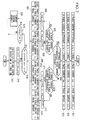
- a motor control device 10 of the present embodiment drives and controls a brushless DC motor 11 (hereafter simply called a motor 11) mounted as the driving source in, for example, a hybrid vehicle, a fuel-cell vehicle, an electric motor vehicle, or another vehicle.
- This motor 11 includes a rotor (not shown) having permanent magnets which are utilized for magnetic fields, and a stator (not shown) which generates a rotating magnetic field to rotate the rotor.
- the motor control device 10 includes a power drive unit (PDU) 13 which employs a battery 12 as a DC power supply, and a control portion 14.
- PDU power drive unit
- this motor control device 10 driving and regenerative operations of the motor 11 with a plurality of phases (for example, the three phases U, V, W) are performed by the PDU 13 which receives control instructions output from the control portion 14.
- a plurality of phases for example, the three phases U, V, W
- the PDU 13 includes a PWM inverter which employs a pulse width modulation (PWM) including a bridge circuit which for example uses a plurality of transistor switching devices in a bridge connection, and a smoothing capacitor; the PDU 13 is connected to the motor 11 and to a high-voltage battery 12 which provides and receives electrical energy.
- PWM pulse width modulation
- the PDU 13 switches between the on (conducting) and off (cutoff) states of each of the transistors forming pairs for each phase in the PWM inverter based on gate signals (that is, PWM signals) which are switching instructions input from the control portion 14, and thereby converts the DC power supplied from the battery 12 into three-phase AC power. And through successive commutation to supply current to the stator windings of the three-phase motor 11, causes alternating U-phase current Iu, V-phase current Iv, and W-phase current Iw to flow in the stator windings for each phase.
- gate signals that is, PWM signals
- the control portion 14 performs a feedback control of current in dq-coordinates, which form a rotating orthogonal coordinate system.
- the control portion 14 computes the d-axis current instruction Idc and q-axis current instruction Iqc based on a torque instruction Tq set according to, for example, the degree of acceleration resulting from operation of acceleration by the driver, calculates the output voltages Vu, Vv, Vw for each phase based on the d-axis current instruction Idc and q-axis current instruction Iqc, and inputs PWM signals which are gate signals, to the PDU 13 according to the output voltages Vu, Vv, Vw for each phase.
- control portion 14 converts two phase currents among the phase currents Iu, Iv, Iq actually supplied from the PDU 13 to the motor 11 into currents in dq-coordinates, and performs control such that the deviations of the d-axis current Id and the q-axis current Iq thus obtained from the d-axis current instruction Idc and q-axis current Iqc are each zero.
- This control portion 14 includes, for example, a target current setting portion 21; a current control portion 22; a dq-three phase conversion portion 23; a PWM signal generation portion 24; a phase current extraction portion 25; a target phase current computation portion 26; a three phase-dq conversion portion 27; an anomaly judgment portion 28; and a revolution rate-angle computation portion 29.
- Input to this control portion 14 are detection signals Ius, Ivs, Iws output from the current sensors 31, 31, 31 for each phase, which detect the phase currents Iu, Iv, Iw of the three phases output from the PDU 13 to the motor 11; detection signals output from the voltage sensor 32 which detects the terminal voltage of the battery 12 (power supply voltage) VB; detection signals output from the rotation sensor 33 which detects the rotor rotation angle ⁇ of the motor 11 (that is, the rotation angle of the magnetic poles of the rotor from a predetermined reference rotation position); and torque instructions Tr output from an external control device (not shown).
- the target current setting portion 21 computes current instructions specifying each of the phase currents Iu, Iv, Iw to be supplied to the motor 11 from the PDU 13, based on torque instructions Tr (for example, instruction values to cause the motor 11 to generate the torque required in response to the amount of operation of depression of the acceleration pedal by the driver) input from for example an external control device (not shown); the revolution rate NM of the motor 11 input from the revolution rate-angle computation portion 29; and the battery voltage VB output from the voltage sensor 32.
- torque instructions Tr for example, instruction values to cause the motor 11 to generate the torque required in response to the amount of operation of depression of the acceleration pedal by the driver
- Tr for example, instruction values to cause the motor 11 to generate the torque required in response to the amount of operation of depression of the acceleration pedal by the driver
- Tr for example, instruction values to cause the motor 11 to generate the torque required in response to the amount of operation of depression of the acceleration pedal by the driver
- Tr for example, instruction values to cause the motor 11 to generate the torque required in response to the amount of operation of depression of
- the dq-coordinates which form a rotating orthogonal coordinate system take for example the d axis (magnetic field axis) in the magnetic pole magnetic flux direction of the rotor permanent magnet, and take the q axis (torque axis) in the direction orthogonal to this d axis, and rotate in synchronization with the rotation phase of the rotor of the motor 11.
- the d-axis target current Idc and q-axis target current Iqc which are DC signals, are applied as current instructions for AC signals supplied to each of the phases of the motor 1 1 from the PDU 13.
- the current control portion 22 calculates the deviation ⁇ Id between the d-axis target current Idc and the d-axis current Id and the deviation ⁇ Iq between the q-axis target current Iqc and the q-axis current Iq, and by means of, for example, a PI (proportional integration) operation according to the motor revolution rate NM input from the revolution rate-angle computation portion 29, performs controlled amplification of the deviation ⁇ Id to calculate the d-axis voltage instruction value Vd, and performs controlled amplification of the deviation ⁇ Iq to calculate the q-axis voltage instruction value Vq.
- PI proportional integration
- the dq-three phase conversion portion 23 uses the rotor rotation angle ⁇ input from the revolution rate-angle computation portion 29 to convert the d-axis voltage instruction value Vd and q-axis voltage instruction value Vq in dq-coordinates into a U-phase output voltage Vu, V-phase output voltage Vv, and W-phase output voltage Vw, which are voltage instruction values in three-phase AC coordinates, which is a static coordinate system.
- the PWM signal generation portion 24 uses pulse-wdith modulation based on for example the sine-wave output voltages Vu, Vv, Vw for each phase, a sawtooth-wave carrier signal, and a switching frequency, to generate gate signals (that is, PWM signals) which are switching instructions including pulses to drive and turn on/off each of the switching devices of the PWM inverter in the PDU 13.
- gate signals that is, PWM signals
- the phase current extraction portion 25 extracts as physical quantities each of the phase currents Iu, Iv, Iw from the detection signals Ius, Ivs, Iws for each of the phase currents, detected by the current sensors 31,31,31.
- the target phase current computation portion 26 uses the rotor rotation angle ⁇ (deg) input from the revolution rate-angle computation portion 29 to calculate, using for example the conversion formula indicated in formula (1) below, each of the target phase currents Iuc, Ivc, Iwc for each of the phase currents, according to the d-axis target current Idc and q-axis target current Iqc output from the target current setting portion 21.
- ⁇ Iuc 2 3 ⁇ Idc ⁇ sin ⁇ + 90 + Iqc ⁇ sin ⁇ + 180
- Ivc 2 3 ⁇ Idc ⁇ sin ⁇ + 330 + Iqc ⁇ sin ⁇ + 60
- Iwc - Iuc - Ivc
- , ⁇ Iv
- , ⁇ Iw
- phase currents Iu, Iv, Iw of the three phases which are currents in a static coordinate system extracted by the phase current extraction portion 25
- the phase currents for the two phases other than the phase corresponding to the largest phase current difference and the rotor rotation angle ⁇ (deg) input from the revolution rate-angle computation portion 29 are used to calculate the rotating-coordinate currents (that is, the d-axis current Id and the q-axis current Iq in dq-coordinates) for the rotation phase of the motor 1 1 from one among the following formulas (2) through (4).
- the three phase-dq conversion portion 27 uses the above formula (2) to calculate the d-axis current Id and the q-axis current Iq based on the phase currents Iu, Iv corresponding to the U phase and V phase, excluding the W phase.
- phase current differences ⁇ Iu, ⁇ Iv, ⁇ Iw for the three phases when the U phase current difference ⁇ Iu is the largest, the d-axis current Id and the q-axis current Iq are calculated using the above formula (3) based on the phase currents Iv, Iw corresponding to the V phase and W phase, excluding the U phase.
- the d-axis current Id and the q-axis current Iq are calculated using the above formula (4) based on the phase currents Iu, Iw corresponding to the U phase and W phase, excluding the V phase.
- the three phase-dq conversion portion 27 sets the flag value of the control flag dq_pat according to the phase corresponding to the largest phase current difference detected from the phase current differences ⁇ Iu, ⁇ Iv, ⁇ Iw for the three phases, and outputs the flag value to the anomaly setting portion 28.
- the three phase-dq conversion portion 27 sets the flag value of the control flag dq_pat to "0", sets the flag value of the control flag dq_pat to "1" when the U phase current difference ⁇ Iu is the largest, and sets the flag value of the control flag dq_pat to "2" when the V phase current difference ⁇ Iv is the largest.
- the anomaly judgment portion 28 judges that an anomaly is occurring in the current sensor 31 corresponding to the phase of this flag value, based on the flag value of the control flag dq_pat output from the three phase-dq conversion portion 27.
- the signal of this judgment result is for example input to the PDU 13, and is referenced during requests to execute the halting of current to the motor 1 1 and in other judgment processing.
- the revolution rate-angle computation portion 29 extracts the rotation angle ⁇ of the motor 11 from the detection signals output from the rotation sensor 33, and computes the revolution rate NM of the motor 11 based on the rotation angle ⁇ .
- the motor control device 10 of the present embodiment includes the configuration described above. Next, the operation of this motor control device 10, and processing to calculate the d-axis current Id and the q-axis current Iq from the phase currents of two phases among the phase currents Iu, Iv, Iw for three phases based on the detection signals of the current sensors 31, 31, 31, are explained referring to the attached drawings.
- steps S01 to S 19 described below are set so as to be executed repeatedly with a predetermined control period, for example, during execution of control operation of the motor 11.
- step S04 a judgment is made as to whether the U phase current difference ⁇ Iu is equal to or greater than the V phase current difference ⁇ Iv. If the judgment result is "YES", then processing proceeds to step S05.
- step S05 a judgment is made as to whether the U phase current difference ⁇ Iu is equal to or greater than the W phase current difference ⁇ Iw.
- step S06 because the U phase current difference ⁇ Iu is the largest among the phase current differences ⁇ Iu, ⁇ Iv, ⁇ Iw for the three phases, the flag value of the control flag dq_pat is set to "1".
- step S07 the d-axis current Id and the q-axis current Iq are calculated from the above formula (3) based on the phase currents Iv and Iw for the V phase and W phase, which are the two phases other than the U phase corresponding to the U phase current difference ⁇ Iu, which is the largest, and processing then proceeds to step S 15 described below.
- step S08 because the W phase current difference ⁇ Iw is the largest among the phase current differences ⁇ Iu, ⁇ Iv, ⁇ Iw for the three phases, the flag value of the control flag dq_pat is set to "0".
- step S09 the above formula (2) is used to calculate the d-axis current Id and the q-axis current Iq based on the phase currents Iu, Iv for the U phase and V phase, which are the two phases other than the W phase corresponding to the W phase current difference ⁇ Iw, which is the largest, and then processing proceeds to step S15 described below.
- step S10 a judgment is made as to whether the V phase current difference ⁇ Iv is equal to or greater than the W phase current difference ⁇ Iw.
- step S 11 because the V phase current difference ⁇ Iv is the largest among the phase current differences ⁇ Iu, ⁇ Iv, ⁇ Iw for the three phases, the flag value of the control flag dq_pat is set to "2".
- step S12 the above formula (4) is used to calculate the d-axis current Id and the q-axis current Iq based on the phase currents Iu, Iw for the U phase and W phase, which are the two phases other than the V phase corresponding to the V phase current difference ⁇ Iv, which is the largest, and then processing proceeds to step S15 described below.
- step S 13 because the W phase current difference ⁇ Iw is the largest among the phase current differences ⁇ Iu, ⁇ Iv, ⁇ Iw for the three phases, the flag value of the control flag dq_pat is set to "0".
- step S14 the above formula (2) is used to calculate the d-axis current Id and the q-axis current Iq based on the phase currents Iu, Iv for the U phase and V phase, which are the two phases other than the W phase corresponding to the W phase current difference ⁇ Iw which is the largest, and then processing proceeds to step S 15.
- step S15 a judgment is made as to whether the flag value of the control flag dq_pat and the flag value of the previous cycle dq_pat_old, which is the value of the control flag dq_pat in the previous processing, are equal.
- step S16 the previous cycle flag value dq_pat_old is set to the flag value of the control flag dq_pat for the current processing.
- step S 17 counting of a timer in the stopped state is initiated, or the count value of a timer in the operating state is initialized and the timer operation is continued, and the series of processing ends.
- step S 18 a judgment is made as to whether the timer value TM of the timer is equal to or greater than a predetermined time #TM.
- step S 19 it is judged that an anomaly is occurring in the current sensor 31 corresponding to the phase of the flag value of the control flag dq_pat, and the series of processing ends.
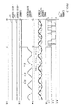
- step S0 1 to step S 19 Through the series of processing of step S0 1 to step S 19 described above, during for example the period from time t0 to time t1 shown in FIG. 3, if each of the current sensors 31, 31, 31 is normal, then the detection signals Ius, Ivs, Iws of the current sensors 31, 31, 31 are sinusoidal in shape, and the d-axis current Id and the q-axis current Iq which are DC signals, are calculated from the phase currents of two phases selected appropriately according to the relative magnitudes of the phase current differences ⁇ Iu, ⁇ Iv, ⁇ Iw.
- the detection signal Ius of this U phase current sensor 33 departs from a sinusoidal shape
- the detection signals Ivs, Iws of the V phase and W phase current sensors 33, 33 are sinusoidal, and the U phase current difference ⁇ Iu is always largest among the phase current differences ⁇ Iu, ⁇ Iv, ⁇ Iw.
- the flag value of the control flag dq_pat is fixed at "1"
- the d-axis current Id and the q-axis current Iq which are DC signals are calculated from the d-axis current Id and the q-axis current Iq based on the phase currents Iv, Iw of the V phase and W phase which are the two phases other than the U phase corresponding to the U phase current difference ⁇ Iu which is the largest current difference.
- the motor control device 10 of the present embodiment two phases other than the phase corresponding to the largest phase current difference are extracted from the three phases, based on the current differences ⁇ Iu, ⁇ Iv, ⁇ Iw which are the absolute values of the differences between the phase currents Iu, Iv, Iw extracted from detection signals of the current sensors 31,31,31 and the target phase currents Iuc, Ivc, Iwc for each phase, and the motor 11 is controlled based on the detection signals of the current sensors 31, 31 for these two phases.
- the motor 11 can be controlled appropriately based on current in two phases with relatively good feedback control following properties.
Landscapes
- Engineering & Computer Science (AREA)
- Power Engineering (AREA)
- Control Of Ac Motors In General (AREA)
Applications Claiming Priority (1)
| Application Number | Priority Date | Filing Date | Title |
|---|---|---|---|
| JP2006042175A JP4926492B2 (ja) | 2006-02-20 | 2006-02-20 | モータ制御装置 |
Publications (2)
| Publication Number | Publication Date |
|---|---|
| EP1821402A1 true EP1821402A1 (de) | 2007-08-22 |
| EP1821402B1 EP1821402B1 (de) | 2009-04-15 |
Family
ID=38109159
Family Applications (1)
| Application Number | Title | Priority Date | Filing Date |
|---|---|---|---|
| EP07102264A Ceased EP1821402B1 (de) | 2006-02-20 | 2007-02-13 | Motorsteuervorrichtung und Motorsteuerverfahren |
Country Status (4)
| Country | Link |
|---|---|
| US (1) | US7576511B2 (de) |
| EP (1) | EP1821402B1 (de) |
| JP (1) | JP4926492B2 (de) |
| DE (1) | DE602007000874D1 (de) |
Cited By (2)
| Publication number | Priority date | Publication date | Assignee | Title |
|---|---|---|---|---|
| EP2403131A3 (de) * | 2010-06-30 | 2017-05-31 | Hitachi Automotive Systems, Ltd. | System zur Umwandlung der elektrischen Energie und Umrichter zur Umwandlung elektrischer Energie |
| CN112649727A (zh) * | 2019-10-11 | 2021-04-13 | 博世华域转向系统有限公司 | 一种rps采集值与电流采集值延时性判断方法 |
Families Citing this family (9)
| Publication number | Priority date | Publication date | Assignee | Title |
|---|---|---|---|---|
| US20080157707A1 (en) * | 2005-03-04 | 2008-07-03 | Ebm-Papst St. Georgen Gmbh & Co. Kg | Electric Motor And Method Of Controllling Said Motor |
| JP4754417B2 (ja) * | 2006-06-26 | 2011-08-24 | 本田技研工業株式会社 | 永久磁石型回転電機の制御装置 |
| JP4556076B2 (ja) * | 2008-04-22 | 2010-10-06 | 本田技研工業株式会社 | 電動機の制御装置 |
| US20140121867A1 (en) * | 2012-11-01 | 2014-05-01 | GM Global Technology Operations LLC | Method of controlling a hybrid powertrain with multiple electric motors to reduce electrical power losses and hybrid powertrain configured for same |
| US9369078B2 (en) | 2013-03-11 | 2016-06-14 | Steering Solutions Ip Holding Corporation | Method of current reference generation for a motor |
| US9461574B2 (en) * | 2013-03-12 | 2016-10-04 | Steering Solutions Ip Holding Corporation | Motor control system for determining a reference d-axis current and a q-axis current |
| US9531311B2 (en) | 2013-03-13 | 2016-12-27 | Steering Solutions Ip Holding Corporation | Generation of a current reference to control a brushless motor |
| US10526008B1 (en) * | 2018-07-31 | 2020-01-07 | Steering Solutions Ip Holding Corporation | Machine current limiting for permanent magnet synchronous machines |
| DE102021201671A1 (de) | 2021-02-23 | 2022-08-25 | Zf Friedrichshafen Ag | Verfahren zur Erfassung wenigstens eines Phasenstroms einer dreiphasigen elektrischen Maschine |
Citations (2)
| Publication number | Priority date | Publication date | Assignee | Title |
|---|---|---|---|---|
| JPH09172791A (ja) * | 1995-12-18 | 1997-06-30 | Toyota Motor Corp | 交流モータ制御回路の異常検出装置 |
| EP1311060A2 (de) * | 2001-11-07 | 2003-05-14 | Hitachi, Ltd. | Regelvorrichtung für ein elektrisches Fahrzeug und Reglungsmethode |
Family Cites Families (17)
| Publication number | Priority date | Publication date | Assignee | Title |
|---|---|---|---|---|
| ATE433222T1 (de) * | 1996-08-19 | 2009-06-15 | Daikin Ind Ltd | Antriebsvorrichtung für einen bürstenlosen gleichstrommotor |
| US6147470A (en) * | 1996-09-13 | 2000-11-14 | Hitachi, Ltd. | Device for controlling induction motor and method of controlling the same |
| JP3527071B2 (ja) * | 1997-07-04 | 2004-05-17 | 株式会社日立製作所 | 電気自動車の制御装置 |
| JP3813637B2 (ja) * | 1998-09-03 | 2006-08-23 | 三菱電機株式会社 | 交流電動機の制御装置 |
| US6014007A (en) * | 1998-09-29 | 2000-01-11 | Allen-Bradley Company Llc | Method and apparatus for starting an AC drive into a rotating motor |
| JP2000116199A (ja) * | 1998-10-01 | 2000-04-21 | Toshiba Corp | 電動機制御装置 |
| JP3572384B2 (ja) | 1998-10-05 | 2004-09-29 | 日産自動車株式会社 | 3相交流モータの制御装置 |
| US6069467A (en) * | 1998-11-16 | 2000-05-30 | General Electric Company | Sensorless rotor tracking of induction machines with asymmetrical rotor resistance |
| JP3515460B2 (ja) * | 1999-12-24 | 2004-04-05 | 本田技研工業株式会社 | 交流モータの制御装置 |
| JP3661572B2 (ja) * | 2000-07-18 | 2005-06-15 | 日産自動車株式会社 | インバーターの電流センサー診断装置 |
| JP3979561B2 (ja) * | 2000-08-30 | 2007-09-19 | 株式会社日立製作所 | 交流電動機の駆動システム |
| JP3867518B2 (ja) * | 2001-06-06 | 2007-01-10 | 株式会社日立製作所 | 同期電動機のセンサレス制御システム |
| JP3582505B2 (ja) * | 2001-09-10 | 2004-10-27 | 日産自動車株式会社 | モーター制御装置 |
| JP3685138B2 (ja) * | 2002-02-18 | 2005-08-17 | 日産自動車株式会社 | モーター制御装置 |
| JP2004096933A (ja) * | 2002-09-03 | 2004-03-25 | Nissan Motor Co Ltd | 3相交流電動機の制御装置 |
| JP3771544B2 (ja) * | 2003-03-24 | 2006-04-26 | 株式会社日立製作所 | 永久磁石形同期電動機の制御方法及び装置 |
| JP2006238631A (ja) * | 2005-02-25 | 2006-09-07 | Mitsubishi Heavy Ind Ltd | Id/Iqテーブルを使用したモータの制御方法 |
-
2006
- 2006-02-20 JP JP2006042175A patent/JP4926492B2/ja not_active Expired - Lifetime
-
2007
- 2007-02-12 US US11/704,971 patent/US7576511B2/en active Active
- 2007-02-13 EP EP07102264A patent/EP1821402B1/de not_active Ceased
- 2007-02-13 DE DE602007000874T patent/DE602007000874D1/de active Active
Patent Citations (2)
| Publication number | Priority date | Publication date | Assignee | Title |
|---|---|---|---|---|
| JPH09172791A (ja) * | 1995-12-18 | 1997-06-30 | Toyota Motor Corp | 交流モータ制御回路の異常検出装置 |
| EP1311060A2 (de) * | 2001-11-07 | 2003-05-14 | Hitachi, Ltd. | Regelvorrichtung für ein elektrisches Fahrzeug und Reglungsmethode |
Cited By (2)
| Publication number | Priority date | Publication date | Assignee | Title |
|---|---|---|---|---|
| EP2403131A3 (de) * | 2010-06-30 | 2017-05-31 | Hitachi Automotive Systems, Ltd. | System zur Umwandlung der elektrischen Energie und Umrichter zur Umwandlung elektrischer Energie |
| CN112649727A (zh) * | 2019-10-11 | 2021-04-13 | 博世华域转向系统有限公司 | 一种rps采集值与电流采集值延时性判断方法 |
Also Published As
| Publication number | Publication date |
|---|---|
| US7576511B2 (en) | 2009-08-18 |
| US20070205743A1 (en) | 2007-09-06 |
| EP1821402B1 (de) | 2009-04-15 |
| JP2007221963A (ja) | 2007-08-30 |
| JP4926492B2 (ja) | 2012-05-09 |
| DE602007000874D1 (de) | 2009-05-28 |
Similar Documents
| Publication | Publication Date | Title |
|---|---|---|
| EP1821402B1 (de) | Motorsteuervorrichtung und Motorsteuerverfahren | |
| US8384323B2 (en) | Motor magnetic-pole-position estimating apparatus | |
| EP1986318B1 (de) | Motorsteuervorrichtung | |
| EP1873900B1 (de) | Steuerung und Steuerungsverfahren für einen Permanentmagnetdrehmotor | |
| US9184683B2 (en) | Applied-voltage electrical angle setting method for synchronous motor, and motor control device | |
| US9077265B2 (en) | Motor control device | |
| US9184681B2 (en) | Vehicle including motor control device, and control method for vehicle | |
| US20110062904A1 (en) | Alternating current motor control system | |
| CN111034013B (zh) | 三相同步电动机的控制装置和使用其的电动助力转向装置 | |
| US12255558B2 (en) | Motor controller, motor system and method for controlling motor | |
| JP4652176B2 (ja) | 永久磁石型回転電機の制御装置 | |
| JP7099226B2 (ja) | モータ制御装置 | |
| JP2010148324A (ja) | モータ制御装置 | |
| JP4781933B2 (ja) | 電動機の制御装置 | |
| US20200059184A1 (en) | Motor controlling method, motor controlling system, and electronic power steering system | |
| US20200007062A1 (en) | Motor controlling method, motor controlling system, and electronic power steering system | |
| US20200001915A1 (en) | Motor controlling method, motor controlling system, and electronic power steering system | |
| JP3578096B2 (ja) | モータ制御装置 | |
| US20200007059A1 (en) | Motor controlling method, motor controlling system, and electronic power steering system | |
| JP4727405B2 (ja) | 電動機の制御装置 | |
| JP2010136585A (ja) | 電動機の制御装置 | |
| JP2010136586A (ja) | 電動機の磁極位置推定装置 | |
| JP2004215316A (ja) | 電動駆動制御装置、電動駆動制御方法及びそのプログラム | |
| CN108476009A (zh) | 永磁体式同步电动机的控制系统及永磁体式同步电动机的控制方法 | |
| KR20250076420A (ko) | 모터 구동 장치, 모터 시스템 및 모터의 구동 방법 |
Legal Events
| Date | Code | Title | Description |
|---|---|---|---|
| PUAI | Public reference made under article 153(3) epc to a published international application that has entered the european phase |
Free format text: ORIGINAL CODE: 0009012 |
|
| AK | Designated contracting states |
Kind code of ref document: A1 Designated state(s): AT BE BG CH CY CZ DE DK EE ES FI FR GB GR HU IE IS IT LI LT LU LV MC NL PL PT RO SE SI SK TR |
|
| AX | Request for extension of the european patent |
Extension state: AL BA HR MK YU |
|
| 17P | Request for examination filed |
Effective date: 20070912 |
|
| 17Q | First examination report despatched |
Effective date: 20071016 |
|
| AKX | Designation fees paid |
Designated state(s): DE GB |
|
| GRAP | Despatch of communication of intention to grant a patent |
Free format text: ORIGINAL CODE: EPIDOSNIGR1 |
|
| GRAS | Grant fee paid |
Free format text: ORIGINAL CODE: EPIDOSNIGR3 |
|
| GRAA | (expected) grant |
Free format text: ORIGINAL CODE: 0009210 |
|
| AK | Designated contracting states |
Kind code of ref document: B1 Designated state(s): DE GB |
|
| REG | Reference to a national code |
Ref country code: GB Ref legal event code: FG4D |
|
| REF | Corresponds to: |
Ref document number: 602007000874 Country of ref document: DE Date of ref document: 20090528 Kind code of ref document: P |
|
| PLBE | No opposition filed within time limit |
Free format text: ORIGINAL CODE: 0009261 |
|
| STAA | Information on the status of an ep patent application or granted ep patent |
Free format text: STATUS: NO OPPOSITION FILED WITHIN TIME LIMIT |
|
| 26N | No opposition filed |
Effective date: 20100118 |
|
| REG | Reference to a national code |
Ref country code: DE Ref legal event code: R084 Ref document number: 602007000874 Country of ref document: DE |
|
| REG | Reference to a national code |
Ref country code: GB Ref legal event code: 746 Effective date: 20141114 |
|
| REG | Reference to a national code |
Ref country code: DE Ref legal event code: R084 Ref document number: 602007000874 Country of ref document: DE Effective date: 20141120 |
|
| PGFP | Annual fee paid to national office [announced via postgrant information from national office to epo] |
Ref country code: GB Payment date: 20160210 Year of fee payment: 10 |
|
| GBPC | Gb: european patent ceased through non-payment of renewal fee |
Effective date: 20170213 |
|
| PG25 | Lapsed in a contracting state [announced via postgrant information from national office to epo] |
Ref country code: GB Free format text: LAPSE BECAUSE OF NON-PAYMENT OF DUE FEES Effective date: 20170213 |
|
| PGFP | Annual fee paid to national office [announced via postgrant information from national office to epo] |
Ref country code: DE Payment date: 20180130 Year of fee payment: 12 |
|
| REG | Reference to a national code |
Ref country code: DE Ref legal event code: R119 Ref document number: 602007000874 Country of ref document: DE |
|
| PG25 | Lapsed in a contracting state [announced via postgrant information from national office to epo] |
Ref country code: DE Free format text: LAPSE BECAUSE OF NON-PAYMENT OF DUE FEES Effective date: 20190903 |