EP1821386A2 - Appareil de charge pour source d'alimentation de type stockage de condensateur et appareil de décharge pour source d'alimentation de type stockage de condensateur - Google Patents
Appareil de charge pour source d'alimentation de type stockage de condensateur et appareil de décharge pour source d'alimentation de type stockage de condensateur Download PDFInfo
- Publication number
- EP1821386A2 EP1821386A2 EP07102294A EP07102294A EP1821386A2 EP 1821386 A2 EP1821386 A2 EP 1821386A2 EP 07102294 A EP07102294 A EP 07102294A EP 07102294 A EP07102294 A EP 07102294A EP 1821386 A2 EP1821386 A2 EP 1821386A2
- Authority
- EP
- European Patent Office
- Prior art keywords
- circuit
- current
- voltage
- charge
- power source
- Prior art date
- Legal status (The legal status is an assumption and is not a legal conclusion. Google has not performed a legal analysis and makes no representation as to the accuracy of the status listed.)
- Withdrawn
Links
Images


Classifications
-
- H—ELECTRICITY
- H02—GENERATION; CONVERSION OR DISTRIBUTION OF ELECTRIC POWER
- H02J—CIRCUIT ARRANGEMENTS OR SYSTEMS FOR SUPPLYING OR DISTRIBUTING ELECTRIC POWER; SYSTEMS FOR STORING ELECTRIC ENERGY
- H02J7/00—Circuit arrangements for charging or depolarising batteries or for supplying loads from batteries
- H02J7/0013—Circuit arrangements for charging or depolarising batteries or for supplying loads from batteries acting upon several batteries simultaneously or sequentially
- H02J7/0014—Circuits for equalisation of charge between batteries
- H02J7/0016—Circuits for equalisation of charge between batteries using shunting, discharge or bypass circuits
-
- H—ELECTRICITY
- H02—GENERATION; CONVERSION OR DISTRIBUTION OF ELECTRIC POWER
- H02J—CIRCUIT ARRANGEMENTS OR SYSTEMS FOR SUPPLYING OR DISTRIBUTING ELECTRIC POWER; SYSTEMS FOR STORING ELECTRIC ENERGY
- H02J7/00—Circuit arrangements for charging or depolarising batteries or for supplying loads from batteries
- H02J7/34—Parallel operation in networks using both storage and other dc sources, e.g. providing buffering
- H02J7/345—Parallel operation in networks using both storage and other dc sources, e.g. providing buffering using capacitors as storage or buffering devices
-
- H—ELECTRICITY
- H02—GENERATION; CONVERSION OR DISTRIBUTION OF ELECTRIC POWER
- H02J—CIRCUIT ARRANGEMENTS OR SYSTEMS FOR SUPPLYING OR DISTRIBUTING ELECTRIC POWER; SYSTEMS FOR STORING ELECTRIC ENERGY
- H02J2207/00—Indexing scheme relating to details of circuit arrangements for charging or depolarising batteries or for supplying loads from batteries
- H02J2207/20—Charging or discharging characterised by the power electronics converter
Definitions
- This invention relates to a charging apparatus for a capacitor storage type power source for electrically charging a capacitor storage type power source storing electric energy in electric double layer capacitors.
- the terminal voltages can fluctuate to a large extent in a high voltage and large capacity energy storage type power source, which is formed by connecting a plurality of electric double layer capacitors in series, as a function of the quantity of charged or discharged electric energy.
- a capacitor storage type power source operates poorly efficiently and gives rise to a problem of withstand current because a large charge current flows in the initial stages of a charging process when charged with electric energy at a constant voltage like a secondary battery. Therefore, such a capacitor storage type power source is charged with electric energy efficiently by way of a constant current charge process.
- a reference values is defined for the charge voltage of the electric double layer capacitors and a parallel monitor is connected to each electric double layer capacitor to limit the terminal voltage of the capacitor, bypassing the charge current, when the terminal voltage (charge voltage) exceeds the reference value because the capacitors that are connected in series can show variances of charge voltage.
- Each of the parallel monitors bypasses the charge current in this way to limit the charge voltage to a predetermined level (full charge voltage that is lower than the withstand voltage) to reduce the variances of charge voltage among the electric double layer capacitors.
- a predetermined level full charge voltage that is lower than the withstand voltage
- the power loss increases in proportion to the operation time and the number of parallel monitors operating to bypass the charge current. Therefore, it is necessary to avoid a situation where the parallel monitors operate to bypass a large charge current for a long time.
- the charging apparatus for electrically charging an energy storage type power source is required to have a power limiter feature of switching from constant current charge to constant power charge when the charge voltage of the entire energy storage type power source rises above a predetermined level due to constant current charge typically by reducing the charge current in response to the rise of the charge voltage (See, for example, Michio Okamura, "Electric Double-Layer Capacitor and Electricity Accumulation System", The Nikkan Kogyo, Shimbun, Ltd., 3rd ed. Sep. 30, 2005, pp. 138-139 and Japanese Patent Publication No. 3306325 ).
- the present invention relates to a charging apparatus for a capacitor storage type power source for electrically charging a capacitor storage type power source storing electric energy in electric double layer capacitors by controlling the charge current, modulating the pulse width by means of a pulse width modulation means from a charge power source.
- the terminal voltages can fluctuate to a large extent in a high voltage and large capacity energy storage type power source, which is formed by connecting a plurality of electric double layer capacitors in series, as a function of the quantity of charged or discharged electric energy.
- a capacitor storage type power source operates poorly efficiently and gives rise to a problem of withstand current because a large charge current flows in the initial stages of a charging process when charged with electric energy at a constant voltage like a secondary battery. Therefore, such a capacitor storage type power source is charged with electric energy efficiently by way of a constant current charge process.
- a parallel monitor is connected to each electric double layer capacitor to limit the terminal voltage (charge voltage) of the capacitor, bypassing the charge current at a predetermined reference voltage because the capacitors that are connected in series can show variances of charge voltage.
- Each of the parallel monitors bypasses the charge current in this way to limit the charge voltage to a predetermined level (full charge voltage that is lower than the withstand voltage) to reduce the variances of charge voltage among the electric double layer capacitors.
- the parallel monitors As the charge voltages of the electric double layer capacitors rise and the parallel monitors sequentially operate to bypass the charge current, the power loss increases and the parallel monitors have withstand current upper limit.
- the charging apparatus for electrically charging an energy storage type power source is required to have a power limiter feature of switching from constant current charge to constant power charge when the charge voltage of the entire energy storage type power source rises above a predetermined level due to constant current charge typically by reducing the charge current in response to the rise of the charge voltage (See, for example, Michio Okamura, "Electric Double-Layer Capacitor and Electricity Accumulation System", The Nikkan Kogyo Shimbun Ltd., 3rd ed. Sep. 30, 2005, pp. 134-139 and Japanese Patent Publications No. 2894444 and No. 3306325 ).
- the present invention relates to a charging apparatus for electrically charging a capacitor storage type power source including a plurality of electric double layer capacitors connected in series for storing electric energy and having respective parallel monitors for bypassing the charge current at a predetermined voltage.
- the terminal voltages can fluctuate to a large extent in a high voltage and large capacity energy storage type power source, which is formed by connecting a plurality of electric double layer capacitors in series, as a function of the quantity of charged or discharged electric energy.
- a capacitor storage type power source operates poorly efficiently and gives rise to a problem of withstand current because a large charge current flows in the initial stages of a charging process when charged with electric energy at a constant voltage like a secondary battery. Therefore, such a capacitor storage type power source is charged with electric energy efficiently by way of a constant current charge process.
- a parallel monitor is connected to each electric double layer capacitor to limit the terminal voltage (charge voltage) of the capacitor, bypassing the charge current at a predetermined reference voltage because the capacitors that are connected in series can show variances of charge voltage.
- Each of the parallel monitors bypasses the charge current in this way to limit the charge voltage to a predetermined level (full charge voltage that is lower than the withstand voltage) to reduce the variances of charge voltage among the electric double layer capacitors.
- a predetermined level full charge voltage that is lower than the withstand voltage
- the power loss increases.
- the present invention relates to a charge/discharging apparatus for a capacitor storage type power source adapted to charge and discharge a capacitor storage type power source for storing electric energy in electric double layer capacitors, the capacitor storage type power source having a main switching circuit to be turned on/off according to an on/off signal and a synchronous rectifier circuit to be turned on/off at phases inverse relative to the main switching circuit to store electric energy in electric double layer capacitors by accumulating energy in a choke coil at the on time of the main switching circuit and discharging the energy accumulated in the choke coil by turning on the synchronous rectifier circuit at the off time of the main switching circuit.
- the terminal voltages can fluctuate to a large extent in a high voltage and large capacity energy storage type power source, which is formed by connecting a plurality of electric double layer capacitors in series, as a function of the square root of the quantity of electric energy stored in the capacitors.
- a PWM (pulse width modulation) control technique is employed in such a charge/discharging apparatus for an energy storage type power source so as to make it efficiently follow the terminal voltages that can fluctuate to a large extent by changing the pulse width to control the charge/discharge operation in a desired manner.
- a switching power source apparatus for storing electric energy in a choke coil by turning on/off a main switching circuit and discharging the stored electric energy by way of a rectifier diode
- the ratio of the loss produced by the rectifier diode rises when obtaining a low voltage DC output. Therefore, the synchronous rectifier circuit (switching circuit) that is turned on/off at phases inverse relative to a main switching circuit is replaced by a rectifier diode to reduce the loss.
- a charge/discharging apparatus for a capacitor storage type power source that employs a PWM control technique can improve the charge/discharge efficiency by using a synchronous rectifier circuit (see, for example, Michio Okamura, "Electric Double-Layer Capacitor and the Electricity Accumulation System", The Nikkan Kogyo Shimbun Ltd., 3rd ed. Sep. 30, 2005, pp. 133-142 and Japanese Patent Publication No. 3626072 ).
- the present invention relates to a charging apparatus for a capacitor storage type power source adapted to charge a capacitor storage type power source for storing electric energy in electric double layer capacitors by pulse width modulation by means of a pulse width modulation means from a charge power source.
- the terminal voltages can fluctuate to a large extent in a high voltage and large capacity energy storage type power source, which is formed by connecting a plurality of electric double layer capacitors in series, as a function of the quantity of charged or discharged electric energy.
- a high voltage and large capacity energy storage type power source which is formed by connecting a plurality of electric double layer capacitors in series, as a function of the quantity of charged or discharged electric energy.
- solar cells When solar cells are employed as charge power source for an energy storage type power source including electric double layer capacitors, they have to be controlled by taking their characteristics into consideration. This is because solar cells have a maximum power point MPP as shown in FIG. 37B of the accompanying drawings and other specific characteristics.
- the specific characteristics of a solar cell include a hill-shaped power characteristic having its peak at the maximum power point MPP and a voltage-current characteristic that the electric current decreases from a maximum current Imax to 0 as the voltage rises until the maximum voltage Vmax is reached while the electric current steeply falls when the voltage passes the maximum power point MPP. These characteristics fluctuate depending on sunlight and the ambient temperature.
- a DC/DC converter between the solar cells and the energy storage type power source so as to make them operate as maximum power point tracker (MPPT) that tracks the maximum power point (MPP) if sunlight changes and also make the converter operate as current source for the electric double layer capacitors.
- MPPT maximum power point tracker
- the output power of the solar cells is subjected to A/D conversion to produce digital data and the obtained digital data are controlled by a microcomputer. More specifically, the load of the solar cells is made to fluctuate minutely and data on the fluctuations are collected. Then, the obtained data are averaged and/or otherwise processed and the processed data are compared with the preceding corresponding data to see if the MPP is directed to the rising side or the falling side of the load current.
- the load of the solar cells is fed back for the purpose of maximizing the output power (See, for example, Michio Okamura, "Electric Double-Layer Capacitor and Electricity Accumulation System", The Nikkan Kogyo Shimbun Ltd., 3rd ed. Mar. 31, 1999, pp. 184-188, 191-194 and Japanese Patent Publication No. 3559803 ).
- the present invention relates to a capacitor storage type power source adapted to generate solar power by means of solar cell panels and store the generated power in capacitors such as electric double layer capacitors.
- capacitors such as electric double layer capacitors are non-Faradic devices that can store electric energy only by exploiting physical phenomena and hence differ from batteries that utilizes chemical reactions.
- capacitors can realize a charge/discharge efficiency higher than 90%, a cycle life of million times and a service life longer than 10 years, which are beyond conceivability for chemical batteries.
- Charging apparatus for capacitor storage type power sources have been proposed to generate solar power by means of solar cells and stores the generated power in capacitors such as electric double layer capacitors.
- FIG. 45 illustrates the relationship of the output current, the output voltage and the output power of a solar cell.
- FIG. 45 shows the output characteristics of a solar cell under certain sunshine conditions and certain temperature conditions.
- the horizontal axis indicates the solar cell current "A” and the vertical axis indicates the solar cell voltage "V” and the solar cell output power "W”.
- the solid line shows the I-V characteristic of the cell, while the dotted line shows the output power characteristic (I-P characteristic).
- the output current of the solar cell increases from 0A to about 0.3A but the output power of the solar cell shows a maximum value of about 0.3W at or near 0.23A (maximum power Pmax) and rapidly falls below 0.1W beyond that current value.
- the output power of a solar cell shows a characteristic curve having a peak value.
- the output characteristic of a solar cell changes as a function of on the sunshine conditions and the temperature conditions and the maximum power Pmax changes accordingly.
- a maximum power point tracking (MPPT) control method is known for constantly taking out a maximum power Pmax in order to raise the generation efficiency and popularly being used.
- Capacitors such as electric double layer capacitors are described in Michio Okamura, “Electric Double-Layer Capacitor and Electricity Accumulation System", The Nikkan Kogyo Shimbun Ltd., 3rd ed. Sep. 30, 2005 and Japanese Patent Application Laid-Open Publication No. 2006-59126 discloses an MPPT control method for solar cells.
- the present invention relates to a charging apparatus for capacitor storage type power source that are very suitable for storing electric energy in capacitors such as electric double layer capacitors.
- Capacitor chargers are provided with a constant voltage mode (CV mode), a constant current mode (CC mode) and a constant power mode (CP mode). Capacitors can be charged with electricity efficiently if it is charged in a constant current mode (CC mode) in the initial stages of the charge process, subsequently in a constant power mode (CP mode) and finally in a constant voltage mode (CV mode) when the process approaches a fully charged condition.
- CV mode constant voltage mode
- CC mode constant current mode
- CP mode constant power mode
- CV mode constant voltage mode
- a technique of PWM (pulse width modulation) control that employs a switching converter is used for capacitor chargers in order to realize a stable power supply. Then, the charge process is controlled in a desired manner by changing the pulse width for the constant voltage mode (CV mode) , the constant current mode (CC mode) and the constant power mode (CP mode).
- CV mode constant voltage mode
- CC mode constant current mode
- CP mode constant power mode
- the DC power applied to the primary winding side of the transformer of the switching converter is periodically turned on and off and the AC power induced at the secondary winding side of the transformer is rectified and smoothed so as to obtain DC power as output power with a voltage shift.
- FIG. 50 illustrates the waveform of the electric current that is produced at the primary side of the transformer of a switching converter. As shown in FIG. 50, the electric power of the Ton period is taken out at the secondary side out of each period T.
- the present invention relates to a charge or discharging apparatus for a capacitor storage type power source adapted to charge or discharge, whichever appropriate, a capacitor storage type power source having a main switching circuit to be turned on/off according to an on/off signal and a choke coil with electric energy.
- the terminal voltages can fluctuate to a large extent in a high voltage and large capacity energy storage type power source, which is formed by connecting a plurality of electric double layer capacitors in series, as a function of the square root of the quantity of electric energy stored in the capacitors.
- a PWM (pulse width modulation) control technique is employed in such a charge or discharging apparatus for an energy storage type power source so as to make it efficiently follow the terminal voltages that can fluctuate to a large extent by changing the pulse width to control the charge/discharge operation (e.g., switching of constant current control CC, constant power control CP and constant voltage control CV) in a desired manner.
- a switching power source apparatus for storing electric energy in a choke coil by turning on/off a main switching circuit and discharging the stored electric energy by way of a rectifier diode
- the ratio of the loss produced by the rectifier diode rises when obtaining a low voltage DC output. Therefore, the synchronous rectifier circuit (switching circuit) that is turned on/off at phases inverse relative to a main switching circuit is replaced by a rectifier diode to reduce the loss.
- a charge/discharging apparatus for a capacitor storage type power source that employs a PWM control technique can improve the charge or discharge efficiency by using a synchronous rectifier circuit (see, for example, Michio Okamura, "Electric Double-Layer Capacitor and Electricity Accumulation system", The Nikkan Kogyo Shimbun Ltd., 3rd ed. Sep. 30, 2005, pp. 135-137 and Japanese Patent Application Laid-Open Publication No. H7-87668 ).
- the present invention relates to a discharging apparatus for discharging electric energy from a capacitor storage type power source for storing electric energy in electric double layer capacitors to a load.
- the terminal voltages can fluctuate to a large extent in a high voltage and large capacity energy storage type power source, which is formed by connecting a plurality of electric double layer capacitors in series, as a function of the square root of the quantity of electric energy stored in the capacitors.
- a PWM (pulse width modulation) control technique is employed in such a discharging apparatus for an energy storage type power source so as to secure a stable power supply from the largely fluctuating terminal voltages for control purposes by changing the pulse width to control the charge/discharge operation (e.g., switching of constant current control CC, constant power control CP and constant voltage control CV) in a desired manner.
- a switching power source apparatus for storing electric energy in a choke coil by turning on/off a main switching circuit and discharging the stored electric energy by way of a rectifier diode
- the ratio of the loss produced by the rectifier diode rises when obtaining a low voltage DC output. Therefore, the synchronous rectifier circuit (switching circuit) that is turned on/off at phases inverse relative to a main switching circuit is replaced by a rectifier diode to reduce the loss.
- a discharging apparatus for a capacitor storage type power source that employs a PWM control technique can improve the charge or discharge efficiency by using a synchronous rectifier circuit (See, for example, Michio Okamura, "Electric Double-Layer Capacitor and Electricity Accumulation System", The Nikkan Kogyo Shimbun Ltd., 3rd ed. Sep. 30, 2005, pp. 135-137 and Japanese Patent Application Laid-Open Publication No. H7-87668 ).
- a synchronous rectifier circuit See, for example, Michio Okamura, "Electric Double-Layer Capacitor and Electricity Accumulation System", The Nikkan Kogyo Shimbun Ltd., 3rd ed. Sep. 30, 2005, pp. 135-137 and Japanese Patent Application Laid-Open Publication No. H7-87668 ).
- the present invention relates to a discharging apparatus for discharging electric energy from a capacitor storage type power source for storing electric energy in electric double layer capacitors to a load.
- a discharging apparatus comprises a regulated power supply circuit so as to secure a stable power supply from the largely fluctuating terminal voltages for control purposes and a PWM (pulse width modulation) control technique is employed so as to make it efficiently follow the terminal voltages that can fluctuate to a large extent by changing the pulse width to control the charge/discharge operation (e.g., switching of constant current control CC, constant power control CP and constant voltage control CV) in a desired manner.
- PWM pulse width modulation
- a switching power source apparatus for storing electric energy in a choke coil by turning on/off a main switching circuit and discharging the stored electric energy by way of a rectifier diode
- the ratio of the loss produced by the rectifier diode rises when obtaining a low voltage DC output. Therefore, the synchronous rectifier circuit (switching circuit) that is turned on/off at phases inverse relative to a main switching circuit is replaced by a rectifier diode to reduce the loss.
- a charge/discharging apparatus for a capacitor storage type power source that employs a PWM control technique can improve the charge or discharge efficiency by using a synchronous rectifier circuit (see, for example, Michio Okamura, "Electric Double-Layer Capacitor and Electricity Accumulation System", The Nikkan Kogyo Shimbun Ltd., 3rd ed. Sep. 30, 2005, pp. 135-137 and Japanese Patent Application Laid-Open Publication No. H7-87668 ).
- the electric power (the product of the voltage and the current) that enters the capacitor is very small in the initial stages of the charge process but increases in proportion to the voltage in the final stages of the charge process.
- the plug socket shows a margin when the capacitor is charged at a constant current and the charge voltage is low but the capacitor becomes short of power when the voltage rises depending on the capacitance of the capacitor. If a low power type charge process is employed, the charge current is high when the voltage is low and falls as the full charge condition comes closes but becomes very large in a voltage region close to nil so that it flows excessively.
- a charging apparatus for electrically charging a capacitor storage type power source adapted to store electric energy in electric double layer capacitors, the apparatus including: a switching circuit for turning on/off the charge current supplied from a charge power source to the capacitor storage type power source; a current detection circuit for detecting the charge current; a voltage detection circuit for detecting the voltage of the capacitor storage type power source; a constant current control circuit for outputting an error amplifying signal for controlling the charge current according to the current value detected by the current detection circuit and a current reference value; a power control circuit for outputting an error amplifying signal for controlling the charge current according to the current value detected by the current detection circuit, the voltage value detected by the voltage detection circuit and a power reference value; a constant voltage control circuit for outputting an error amplifying signal for controlling the charge current according to the voltage value detected by the voltage detection circuit and a voltage reference value; a logical OR circuit for selecting one of the error amplifying signals output from the constant current control circuit, the power control circuit and the
- a charging apparatus for electrically charging a capacitor storage type power source adapted to store electric energy in electric double layer capacitors, the apparatus including: a switching circuit for turning on/off the charge current supplied from a charge power source to the capacitor storage type power source; a current detection circuit for detecting the charge current; a voltage detection circuit for detecting the voltage of the capacitor storage type power source; a constant current control circuit for outputting an error amplifying signal for controlling the charge current according to the current value detected by the current detection circuit and a current reference value; a power control circuit for outputting an error amplifying signal for controlling the charge current according to the current value detected by the current detection circuit, the voltage value detected by the voltage detection circuit and a power reference value; a constant voltage control circuit for outputting an error amplifying signal for controlling the charge current according to the voltage value detected by the voltage detection circuit and a voltage reference value; a logical OR circuit for selecting one of the error amplifying signals output from the constant current control circuit, the power control circuit and the constant voltage control
- the logical OR circuit selects one of the error amplifying signals output from the constant current control circuit, the power control circuit and the constant voltage control circuit and outputs it and the control circuit generates a pulse width modulation signal to turn on/off the switching circuit and control the charge current. Therefore, it is possible to charge a capacitor storage type power source by causing the pulse width to efficiently follow the capacitor voltages that fluctuate to a large extent by means of a simple arrangement so that the constant current mode can be switched to a constant power mode and then to a constant voltage mode smoothly. Additionally, since a plurality of reference values are provided for the switching operation, it is possible to flexibly shift the switching points for selecting a constant current mode, a constant power mode or a constant voltage mode.
- the charge current can be boosted to realize a high speed charge operation by using another charging apparatus for a capacitor storage type power source as master apparatus, the proper charging apparatus operating as slave apparatus, so that the detection signal for the charge current of the master apparatus can be introduced into the slave apparatus as reference value.
- the above object is achieved by providing a charging apparatus for a capacitor storage type power source adapted to store electric energy in electric double layer capacitors, the apparatus charging the power source, controlling the charge current by modulating the pulse width by a pulse width modulation means from a charge power source, the apparatus including: a constant current signal generation means for comparing the first reference value and the charge current and generating an error amplifying signal; a current diminishing signal generation means for inputting the detection signal of the charge voltage of the capacitor storage type power source to the inverted input terminal of an operational amplifier by way of a resistor and an offset value to the non-inverted input terminal and comparing the second reference value taken out from a subtraction circuit formed by connecting a resistor between the inverted input terminal and the output terminal and the charge current to generate an error amplifying signal; and an logical OR circuit for inputting the error amplifying signal of the constant current signal generation means and the error amplifying signal of the current diminishing signal generation means, executing a logical OR process on the input error amplifying signals
- a charging apparatus for a capacitor storage type power source adapted to store electric energy in a plurality of electric double layer capacitors provided with respective parallel monitors for bypassing the charge current at a predetermined voltage, the apparatus charging the power source, controlling the charge current by modulating the pulse width by a pulse width modulation means from a charge power source, the apparatus including: a constant current signal generation means for comparing the first reference value and the charge current and generating an error amplifying signal; a current diminishing signal generation means for comparing the second reference value obtained by inverting the charge voltage of the capacitor storage type power source and turning it into a positive value by means of an offset value and the charge current to generate an error amplifying signal; a switching circuit for switching effectiveness/ineffectiveness of the error amplifying signal of the current diminishing signal generation means; and a logical OR circuit for inputting the error amplifying signal of the constant current signal generation means and the error amplifying signal of the current diminishing signal generation means made effective by the switching circuit, executing a
- the present invention it is possible to generate a reference value by means of a simple circuit configuration as the reference value is inversely proportional to the rise of the charge voltage of the capacitor storage type power source. Then, it is possible to reduce the charge current in inverse proportion to the rise of the charge voltage when the capacitor storage type power source is charged until the charge voltage gets to a predetermined level in a constant current mode by means of a simple circuit configuration as the circuit for controlling the charge current according to the reference value and the charging circuit that controls the charge current to a constant level are connected in parallel.
- a charging apparatus adapted to switch from a constant current mode to a charge mode equivalent to a constant power mode can be realized without using a costly multiplier and the switching points can be defined by way of simple adjustment operation of adjusting the set reference value.
- the switching points can be defined by way of simple adjustment operation of adjusting the set reference value.
- FIG. 25 is a schematic circuit diagram of a parallel monitor.
- C denotes a electric double layer capacitor and CMP denotes a comparator
- D, Tr respectively denote a diode and a transistor
- Vr denotes a set voltage.
- Parallel monitors are respectively connected between the terminals of the plurality of capacitors that are connected in series to form the energy storage type power source and provided with comparators.
- Each of the comparators is adapted to compare the charge voltage of the corresponding capacitor and the set voltage.
- each of parallel monitor operates as a voltage monitor/control device that bypasses the charge current when the set voltage is exceeded and detects a full charge condition to generate a full charge signal so that the capacitor can be charged maximally within the withstand voltage.
- the comparator CMP compares the voltage of the capacitor C and the set voltage Vr and monitors the capacitor C. When the voltage of the capacitor C exceeds the set voltage Vr, the parallel monitor turns the transistor Tr on and bypasses the charge current.
- FIG. 26 is a schematic illustration of a charging apparatus for electrically charging a plurality of electric double layer capacitors that are provided with respective parallel monitors.
- C1, C2, ..., Cn denote respective electric double layer capacitors that are connected in series and M1, M2, ..., Mn denote parallel monitors connected in parallel with the respective electric double layer capacitors C1, C2, ..., Cn
- CH denotes a charging apparatus.
- the charging apparatus CH lowers the charge current to the withstand current value of the parallel monitors once one of the electric double layer capacitors C1, C2, ..., Cn starts bypassing the current.
- the current value is typically about several amperes and hence much smaller than the charge current that is typically about 10 to 60A. Since the parallel monitor of the bypassing capacitor outputs a full charge signal when the bypassing starts so that the charging apparatus CH lowers the charge current to the level of the withstand current value of the parallel monitors when it receives a full charge signal.
- FIG. 27 is a circuit diagram of an equivalent circuit of an electric double layer capacitor including its internal resistance component. Since a capacitor has such an internal resistance component, the full charge voltage at the terminals of the capacitor includes the voltage fall due to the internal resistance. Thus, there arises a problem that the parallel monitor stops outputting a full charge signal the instance when the charge current is lowered to the level of the withstand current value as described above (because Vr is reduced as the voltage fall is reduced so that Vr + Vc that is the terminal voltage does not get to the full charge voltage). The voltage fall due to the internal resistance is large when the current value is large. As the charge voltage is lowered to the level of the withstand current value according to the full charge signal output from the parallel monitor, the capacitor that apparently gets to the full charge voltage has to be charged by the withstand current of its parallel monitor that is far smaller than the ordinary charge current.
- a charging apparatus for a capacitor storage type power source adapted to store electric energy in a plurality of electric double layer capacitors connected in series and provided with respective parallel monitors for bypassing the charge current at a predetermined voltage, the apparatus charging the power source, controlling the charge current by modulating the pulse width by a pulse width modulation means from a charge power source, the apparatus including: a first charge current control means for lowering the charge current in inverse proportion to the increase of the charge voltage of the capacitor storage type power source; and a second charge current control means for flowing the charge current of the withstand current value of the parallel monitors; the apparatus operating the second charge current control means to control the charge current for a predetermined time period upon detecting one of the parallel monitors bypassing the charge current and subsequently the first charge current control means to control the charge current for another predetermined time period.
- a light load of a charge/discharging apparatus for a capacitor storage type power source typically corresponds to a charge operation where the charge current is reduced as the capacitors come close to a full charge condition or a discharge operation where the discharge current is reduced to stop the discharge to the load as the remaining charges of the capacitors become small.
- An inverse current starts the instance when the choke coil completely loses energy. The problem is unnegligible because the capacitors have a large storage capacity and shows a high output level if compared with secondary batteries.
- the above object is achieved by providing a charging apparatus for an capacitor storage type power source, the capacitor storage type power source having a main switching circuit to be turned on/off according to an on/off signal and a synchronous rectifier circuit to be turned on/off at phases inverse relative to the main switching circuit to store electric energy in electric double layer capacitors by accumulating energy in a choke coil at the on time of the main switching circuit and discharging the energy accumulated in the choke coil by turning on the synchronous rectifier circuit at the off time of the main switching circuit, the apparatus including: a current detection circuit for detecting the charge current; a voltage detection circuit for detecting the charge voltage of the electric double layer capacitors; a constant current control circuit for performing an operation of comparing the current detection value detected by the current detection circuit and a current reference value to output an error amplifying signal; a power control circuit for performing an operation of comparing the current detection value detected by the current detection circuit and a power reference value to output an error amplifying signal; a constant voltage control circuit for performing an operation of
- the power control circuit is adapted to subtract the voltage value detected by the voltage detection circuit from the reference value and set the power reference value according to the difference obtained by the subtraction and that the pulse width detection circuit includes a rectifying and smoothing circuit for rectifying and smoothing the on/off signal and a transistor circuit controlled so as to be turned off when the output of the rectifying and smoothing circuit gets to a predetermined value and hold the signal for turning on/off the synchronous rectifier circuit to an off state.
- the signal of the synchronous rectifier circuit is obtained by inverting the on/off control signal by means of an inversion circuit and the main switching circuit and the synchronous rectifier circuit are supplied with an on/off signal by way of a delay circuit that delays the signal at the rising edge of a pulse.
- the delay circuit is formed by inserting a parallel circuit of a diode showing the polarity opposite to the signal and a resistor in series and connecting a capacitor to the output side of the parallel circuit.
- a diode is connected to the polarity for discharging the energy accumulated in the choke coil in parallel with the synchronous rectifier circuit to detect the pulse width of the on part of the on/off control signal as fallen blow a predetermined value and the synchronous rectifier circuit is held to an off state regardless of the on/off control signal so that it is possible to prevent the synchronous rectifier circuit from being turned on and both the charge current and the discharge current from flowing inversely by way of the synchronous rectifier circuit when the load is light.
- an electric current flows to the diode to give rise to a current loss only when the load is light and hence the loss is small so that the energy accumulated in the choke coil is discharged by way of the synchronous rectifier circuit under normal conditions.
- the loss is minimized as a whole and it is possible to eliminate wasteful charges/discharges and improve the charge/discharge efficiencies.
- the above problems are dissolved by realizing a simple circuit configuration that accommodate the characteristics of solar cells and can reduce the cost of the parts and the product when a capacitor storage type power source is electrically charged by using solar cells as charge power source.
- a charging apparatus for a capacitor storage type power source adapted to store electric energy in electric double layer capacitors, the apparatus charging the power source, controlling the charge current by modulating the pulse width by a pulse width modulation means from a charge power source, the apparatus at least including: a constant current signal generation means for comparing the charge current of the capacitor storage type power source with a current reference value and generating an error amplifying signal for holding the charge current to a constant level by limiting the charge current at the time of exceeding the current reference value; an input constant voltage signal generation means for comparing the input voltage from the charge power source with an input voltage reference value and generating an error amplifying signal for holding the input voltage to a constant level by lowering the charge current at the time of falling of the input voltage below the input voltage reference value and by raising the charge current at the time of rising of the input voltage above the input voltage reference value; and a current diminishing signal generation means for setting a current diminishing reference value according to the value obtained by subtracting the voltage of the capacitor storage type power source from
- the input constant voltage signal generation means connects with the logical OR circuit by way of a switching circuit for controlling the sending out of the error amplifying signals.
- the input voltage reference value is the solar cell voltage close to the maximum power point of the solar cells.
- the input voltage reference value changes according to the sunshine conditions.
- the logical OR circuit compares the charge voltage of the capacitor storage type power source defined by the constant voltage signal generation means with a charge voltage reference value along with the error amplifying signals, compares the charge power of the capacitor storage type power source defined by the error amplifying signals for limiting the charge current when the charge voltage exceeds the charge voltage reference value and the constant power signal generation means, and executes a logical OR process on the error amplifying signals for limiting the charge current to supply the outcome of the logical OR process to the pulse width modulation means, when the charge power exceeds the charge power reference value.
- a capacitor storage type power source when a capacitor storage type power source is electrically charged by using solar cells having a maximum power point at a voltage lower than the maximum voltage as charge power source, it is possible to prevent the solar cells from charging the capacitor storage type power source in a voltage region where the voltage of the solar cells falls below the maximum power point without using a costly power tracker mechanism unlike conventional charging apparatus adapted to follow the maximum power point MPP of the solar cells.
- a control feature is provided and operated to control the input constant voltage so as to limit the charge current when the input voltage is compared with an input voltage reference value and found to be lower than the latter. Then, the control feature is realized by a simple circuit arrangement without using a specific program to reduce the cost of the components and hence the entire product.
- An orthodox technique of controlling maximum power point tracking is detecting the solar cell voltage and the solar cell current, computing the power value along with the power values when the solar cell voltage is raised and lowered by means of a computer and detecting the maximum power point of the solar cells from the difference of the power values before and after the voltage change. If the power value is greater after the voltage change, the solar cell voltage is made to change in the same direction. If, on the other hand, the power value is smaller than the voltage change, the solar cell voltage is made to change in the opposite direction. Then, this operation is repeated to make the solar cells approach the maximum power point.
- the above problems are dissolved by providing a charging apparatus for a capacitor storage type power source, the apparatus having solar cells, a power conversion circuit and capacitors so as to convert the output power of the solar cells by means of the power conversion circuit and store the converted power in the capacitors, the apparatus including: a sweep section for sweeping the input voltage of the power conversion circuit within a predetermined range; and a current detection section for detecting the charge current to the capacitors; the current detection section being adapted to detect the change in the charge current to the capacitors produced by the sweep of the input voltage by the sweep means; the input voltage maximizing the charge current being defined as the maximum power point of the solar cells.
- the above problems are dissolved also by providing a charging apparatus for a capacitor storage type power source, the apparatus having solar cells, a power conversion circuit and capacitors so as to convert the output power of the solar cells by means of the power conversion circuit and store the converted power in the capacitors, the apparatus including: a sweep section for sweeping the input voltage of the power conversion circuit within a predetermined range; and a voltage detection section for detecting the charge voltage to the capacitors; the voltage detection section being adapted to detect the change with time of the charge voltage to the capacitors produced by the sweep of the input voltage by the sweep means; the input voltage maximizing the change with time of the charge voltage being defined as the maximum power point of the solar cells.
- the present invention it is no longer necessary to detect the solar cell voltage and the solar cell current and multiply them by each other so that the circuit arrangement (hardware) can be simplified. Additionally, according to the present invention, it is possible to charge a capacitor storage type power source by means of a capacitor system having solar cells in an adverse environment where the ambient temperature is extremely high or low because the maximum power point of the solar cells is determined from the actually stored energy that involves the efficiency of the power conversion circuit.
- capacitor chargers that can realize a constant power charge mode (CP mode) solely at the primary side without feedback control are being studied.
- a constant power charge mode (CP mode) can be realized by utilizing the fact that a constant power level can be produced at the secondary side by controlling the input side so as to make it show a constant voltage and a constant current if the switching converter is assumed to have a constant efficiency.
- a PFC (power factor correction) circuit can be arranged upstream relative to the charger in order to satisfy the requirement of constant voltage at the input side. Then, it is possible to realize a constant power charge mode (CP mode) without feedback control only by controlling the input side so as to make it show a constant current. However, to do this, it is necessary to sense the average current at the primary side.
- an IC for a switching converter is provided with an anti-overcurrent feature as one of its features.
- the peak current that flows at the primary side of the transformer of the switching converter is monitored to protect the transformer and the oscillation is suspended when there is a risk of overcurrent.
- An overcurrent can flow due to a phenomenon of magnetic saturation of the core of the transformer. As magnetic saturation appears in the core of the transformer, the L-component of the transformer disappears and a short-circuit current flows to the primary side of the transformer where the impedance is lost. Such a short-circuit current operates as overcurrent for the IC for the switching converter that eventually destroys the IC. For this reason, an IC for a switching converter is provided with an anti-overcurrent feature as pointed out above.
- FIG. 51 shows the current waveform that appears at the primary side of the transformer when magnetic saturation takes place in the core of the transformer. To exploit the anti-overcurrent feature of the IC, it is necessary to detect the peak current that flows at the primary side.
- the primary side of the switching converter requires a circuit for detecting the average current for realizing a constant power charge mode (CP mode) and the peak current for exploiting the anti-overcurrent feature of the IC.
- CP mode constant power charge mode
- the overall circuit configuration will become complex and costly.
- the above problem is dissolved by providing a charging apparatus for a capacitor storage type power source adapted to induce an electric current in the secondary side winding by turning on/off the DC current applied to the primary side winding of a transformer by means of a switching element, rectify and smooth the induced current and supply the current to capacitors to charge the capacitors, the apparatus including: a power factor improvement circuit for generating the DC current; a PMW control section for controlling the on/off operation of the switching element; and a current transformer having a primary side connected to the primary side winding of the transformer in series and a secondary side connected to a CT circuit detection circuit section; the CT circuit detection circuit section being adapted to take out a voltage proportional to the average current flowing through the primary side winding of the transformer and a voltage proportional to the peak current flowing through the primary side winding of the transformer.
- the circuit configuration is simplified to provide an advantage of cost reduction.
- a capacitor storage type power source provides an advantage that it can be electrically charged at high speed but, at the same time, is accompanied by a problem of discharging a large current and rapidly flowing out the accumulated energy. Therefore, it is important for a charge or discharging apparatus for electrically charging or discharging, whichever appropriate, such a power source to be provided with a means for preventing energy from leaking out and being wasted.
- a charge or discharging apparatus for a capacitor storage type power source, the apparatus having a main switching circuit for performing on/off operations according to on/off control signals and a choke coil and adapted to electrically charge or discharge the electric double layer capacitors of the power source, the apparatus including: a signal intercept circuit inserted and connected in series to the signal line connected to the circuit for electrically charging or discharging the capacitor storage type power source for the purpose of detecting the current and the voltage at the time of charge or discharge, whichever appropriate; the signal intercept circuit being adapted to intercept the signal of the signal line on the condition of the voltage being nil at the side opposite to the side of connecting the main switching circuit and the choke coil to the capacitor storage type power source.
- a charging apparatus for a capacitor storage type power source having a main switching circuit for performing on/off operations according to on/off control signals and a choke coil and adapted to electrically charge the electric double layer capacitors of the power source
- the apparatus including: a current detection circuit for detecting the charge current; a voltage detection circuit for detecting the voltage of the capacitor storage type power source; a constant current control circuit for outputting an error amplifying signal for controlling the charge current according to the current value detected by the current detection circuit and a current reference value; a power control circuit for outputting an error amplifying signal for controlling the charge current according to the current value detected by the current detection circuit, the voltage value detected by the voltage detection circuit and a power reference value; a constant voltage control circuit for outputting an error amplifying signal for controlling the charge current according to the voltage value detected by the voltage detection circuit and a voltage reference value; a logical OR circuit for selecting one of the error amplifying signals output from the constant current control circuit, the power control circuit and
- a discharging apparatus for a capacitor storage type power source having a main switching circuit for performing on/off operations according to on/off control signals and a choke coil and adapted to electrically discharge the electric double layer capacitors of the power source, the apparatus : a current detection circuit for detecting the discharge current; a voltage detection circuit for detecting the voltage of the capacitor storage type power source; and a control circuit for inputting the detected discharge current and voltage and turning on/off the main switch circuit to control the discharge current; a signal intercept circuit being inserted and connected in series to the signal line for detecting the discharge current of the current detection circuit and the signal line for detecting the voltage of the voltage detection circuit, the signal intercept circuit being adapted to intercept the signals of the signal lines on the condition of the voltage being nil at the side opposite to the side of connecting the main switching circuit and the choke coil to the capacitor storage type power source.
- the signals on the signal lines for detecting the current and the voltage at the time of charge or discharge by means of a signal intercept circuit after determining the condition where the charge or discharge operation is stopped so that it is possible to eliminate the power loss due to a wasteful leak current that flows from the capacitor storage type power source storing electric energy by way of the signal lines and raise the charge/discharge efficiency of the capacitor storage type power source.
- it is possible to determine the condition where the charge or discharge operation is stopped by determining the condition of being cut off of the charge power source for charging or discharging the capacitor storage type power source and also determine the off condition of the main switching circuit by determining if the voltage is being applied or not by means of a simple circuit configuration.
- capacitor storage type power source formed by combining a plurality of electric double layer capacitors and an electronic circuit having an initialization feature and a bank switching feature as ECS (energy capacitor system) or ECaSS (energy capacitor system) (tradenames).
- ECS energy capacitor system
- ECaSS energy capacitor system
- components may be prepared in advance as modules such as capacitor modules of 16V, 30V, 60V and so on, charging circuit modules and discharging circuit modules, which may be combined selectively and appropriately in response to the request of the client in order to reduce the system design period and raise the degree of design freedom.
- a discharging circuit module is required to have the ability of producing a sub power source that corresponds to any of various capacitor modules of 16V, 30V, 60V and so on and can accommodate voltage fluctuations of the capacitor module.
- a discharging circuit module is required to operate in a very flexible manner under control.
- Non-Patent Document 1 describes that the electric power can be exploited by 94% when the capacitors are operated until the capacitor voltage falls to 1/4 of the full charge voltage. While the efficiency does not include the loss at the charge/discharging circuit, the Non-Patent Document 1 shows that the power stored in the capacitors can be utilized until the capacitor voltage falls to 1/4 of the full charge voltage to achieve a high efficiency of 94%. Thus, ideally, the stored power needs to be utilized until the capacitor voltage falls to 1/4 of full charge voltage if it is possible.
- the above problem is dissolved by providing a discharging apparatus for a capacitor storage type power source, the apparatus being separated from the charging apparatus for a capacitor storage type power source and adapted to discharge electric energy from the capacitor storage type power source storing electric energy in electric double layer capacitors to a load and charging the capacitor storage type power source with electric energy, the apparatus including: a control circuit for controlling the discharge of electric energy to the load; a main power supply circuit for supplying circuit drive power to the control circuit; an auxiliary power supply circuit for boosting the voltage of the capacitor storage type power source to the operating voltage of the main power supply circuit and supplying circuit drive power to the main power supply circuit; and a voltage boosting operation control circuit adapted to turn off the auxiliary power supply circuit when the voltage of the capacitor storage type power source is not lower than a predefined value to output the voltage of the capacitor storage type power source to the main power supply circuit but turn on the auxiliary power supply circuit when the voltage of the capacitor storage type power source is lower than the predefined value to output the voltage of the capacitor storage
- the above object is achieved by providing a discharging apparatus of a capacitor storage type power source for discharging electric energy from the capacitor storage type power source storing electric power in electric double layer capacitors to a load
- the apparatus including: a control circuit having a control power supply circuit and adapted to control the electric discharge; an intercept circuit for turning on/off the power feed circuit for feeding electric power from the capacitor storage type power source to the control power supply circuit; a bias voltage supply circuit for supplying a bias voltage to the intercept circuit; a judge circuit for determining the discharge condition or the suspended discharge condition and controlling the bias voltage supply circuit so as to turn off the supply of the bias voltage in the suspended discharge condition; and a high impedance circuit for connecting the power feed circuit through a high impedance element to the judge circuit for determining the discharge condition or the suspended discharge condition and controlling the bias voltage supply circuit; the electric current flowing in the suspended discharge condition being limited by the high impedance element.
- said bias voltage supply circuit constitutes a circuit for supplying a constant current bias voltage.
- said control circuit is a circuit for controlling operations of turning on/off the discharge current according to pulse width modulation signals.
- said judge circuit determines the condition of the switch for suspending the electric discharge, the presence or absence of a signal for controlling the electric discharge of said control circuit or the presence or absence of a voltage at the load side.
- the control power supply circuit includes a voltage boosting circuit for boosting the voltage of the electric power fed from the capacitor storage type power source and a voltage stabilizing circuit connected to the voltage boosting circuit to stabilize the output voltage.
- the voltage boosting circuit includes a switching converter formed by connecting a choke coil and a switching circuit in series and adapted to take out a boosted voltage from the connection point of the series connection according to on/off of the switching circuit and the switching circuit is adapted to be switched from a voltage boosting mode for turning on/off the switching circuit to a voltage non-boosting mode for holding the switching circuit in an off condition and vice versa.
- the switching converter switches to the voltage-boosting mode after determining that the voltage of the power fed from the capacitor storage type power source to be not higher than 1/2 of the full charge voltage thereof.
- a suspended discharge condition is determined to turn on/off the power feed circuit of the control power supply circuit so that it is possible to prevent the power accumulated in the electric double layer capacitors of the capacitor storage type power source from being decreased due to the leak currents from the control power supply circuit for controlling electric discharges if the capacitor storage type power source left with the discharging apparatus connected thereto for a long period of time.
- the electric current that flows to the circuits when the power feed circuit is turned off is limited to only the current flowing through the high impedance element so that it is possible to minimize the leak currents that flow in a suspended discharge condition. Therefore, it is possible to improve the effective efficiency of the discharging apparatus and suppress the emission of heat of the discharging apparatus.
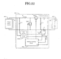
- FIG. 1 is a circuit diagram of the main circuit of an embodiment of charging apparatus for a capacitor storage type power source according to the present invention
- FIG. 1 is a circuit diagram of the main circuit of an embodiment of charging apparatus for a capacitor storage type power source according to the present invention
- FIG. 2 is a circuit diagram of the signal processing circuit of an embodiment of charging apparatus for a capacitor storage type power source.
- a constant current signal generation circuit 101 a constant current signal generation circuit 101, a constant power signal generation circuit 102, a constant voltage signal generation circuit 103, a charge power source 105, a charging apparatus 106, a capacitor storage type power source 107, a signal processing circuit 1061, a PWM signal generation circuit 1062, an amplifier 1063, an inverting amplifier 1064, electric double layer capacitors 1071, analog switches AS11, AS12, AS21, AS22, capacitors C1, C2, diodes D11, D21, D31, a coil L, a current detecting resistor R, a main switch circuit SW1, a synchronous rectifier circuit SW2, current reference value setting circuit Vrefi1, Vrefi2, a power reference value setting circuit Vrefp, charge voltage reference value setting circuit Vrefv1, Vrefv2, a charge current I, a charge voltage Vc and an input voltage Vi.
- the charging apparatus for a capacitor storage type power source of this embodiment of FIG. 1 is adapted to electrically charge a capacitor storage type power source 107 formed by connecting a plurality of electric double layer capacitors 1071 in series from a charge power source 105 by way of a charging apparatus 106 and store electric energy in them.
- Each of the plurality of electric double layer capacitors 1071 of the capacitor storage type power source 107 are provided with respective parallel monitors that are connected in parallel to bypass the charge current when the charge voltage is raised and gets to a predetermined reference voltage.
- the charging apparatus 106 is realized by connecting a choke coil L for charge control and a synchronous rectifier circuit SW2 in series between the charge power source 105 and the capacitor storage type power source 107, then a main switch circuit SW1 to the series connection point in parallel and then smoothing capacitors C1, C2 in parallel between the input side and the output side to form a voltage boosting switching converter and subsequently inserting and connecting a current detecting resistor R in series in order to detect the charge current I.
- the signal processing circuit 1061 is to control the charge current by turning on/off the main switch circuit SW1 and the synchronous rectifier circuit SW2 at phases inverse relative to each other according to on/off control signals.
- the signal processing circuit 1061 detects the charge current I, the charge voltage Vc and the input voltage Vi, compares them with respective reference values defined for control purposes and generates and outputs on/off control signals according to the error amplifying signals produced as a result of the comparisons.
- the on/off control signals are modulated for the pulse width depending on the charge mode in effect, which may be a constant current mode, a constant power mode or a constant voltage mode. More specifically, as shown in FIG.
- the signal processing circuit 1061 includes a constant current signal generation circuit 101, a constant power signal generation circuit 102, a constant voltage signal generation circuit 103 and a PWM signal generation circuit 1062.
- the circuits (1 through 3) for generating error amplifying signals respectively compare the reference values set by the current reference value setting circuit Vrefi1 or Vrefi2, the constant power reference value setting circuit Vrefp, the constant voltage reference value setting circuit Vrefv1 or Vrefv2 with the detection signals of the charge current I and the charge voltage Vc to output error amplifying signals. Then, one of the error amplifying signals is selected by the switching operation of the logical OR circuit having diodes D11, D21, D31 and input to the PWM signal generation circuit 1062.
- an on/off control signal (PWM signal) that is modulated for the pulse width is generated from the PWM signal generation circuit 1062 and output to the main switching circuit SW1 and the synchronous rectifier circuit SW2 respectively by way the amplifier 1063 and the inverting amplifier 1064.
- the constant current signal generation circuit 101 can select one of a plurality of current reference value setting circuits Vrefi1 and Vrefi2 by means of analog switches AS11, AS12 and change the selected current reference value while the constant voltage signal generation circuit 103 can select one of a plurality of constant voltage reference value setting circuits Vrefv1 and Vrefv2 by means of analog switches AS31, AS32 and change the reference value.
- the selection of the current reference value Vrefi1 or Vrefi2 is realized under the condition that any of the parallel monitors that are connected to the respective electric double layer capacitors 1071 in parallel bypasses the charge current (according to a full charge signal: F signal) while the withstand current upper limit value of the parallel monitors is held low relative to the withstand current upper limit value of the electric double layer capacitors 1071.
- the analog switch AS11 is held on by means of selection signal refi1 and the analog switching AS12 is held off by means of selection signal refi2 until any of the parallel monitors bypasses the charge current so as to electrically charge the electric double layer capacitors 1071 with a large charge current that corresponds to the withstand current upper limit value.
- the analog switch AS11 is turned off by means of selection signal refi1 and the analog switch AS12 is turned on by means of selection signal refi2 so as to select a charge current level lower than the withstand current upper limit value of the parallel monitors.
- the analog switch AS11 is turned off by means of selection signal refi1 and the analog switch AS12 is turned on by means of selection signal refi2 so as to select a charge current level lower than the withstand current upper limit value of the parallel monitors.
- the value of the charge current detected by the master charging apparatus is made to be equal to the current reference value of the slave charging apparatus.
- the analog switch AS11 is turned on by means of selection signal refi1 and the analog switch AS12 is turned off by means of selection signal refi2 in the single master charging apparatus, while the analog switch AS11 is turned off by means of selection signal refi1 and the analog switch AS12 is turned on by means of selection signal refi2 in all the slave charging apparatus in order to select the detected value of the charge current taken out from the master charging apparatus as current reference value. Then, the plurality of charging apparatus does not operate independently.
- the plurality of charging apparatus can be synchronously controlled by selecting one of them as master charging apparatus and selecting the charge current output from the master charging apparatus as current reference value for all the slave charging apparatus. Then, it is possible to increase the entire charge current and charge the capacitor storage type power source at high speed.
- the selection of one of the constant voltage reference value setting circuits Vrefv1, Vrefv2 is typically realized by means of external signals (refv1, refv2) such as the output signals of a rated voltage switch.
- external signals refv1, refv2
- the analog switch AS31 is turned on by means of selection signal refv1 to select the constant voltage reference value Vrefv1 in an ordinary operation mode but the analog switch AS32 is turned on by means of selection signal refv2 to select the constant voltage reference value Vrefv2 in a longevity operation mode.
- FIG. 3 is a circuit diagram of an embodiment of constant voltage signal generation circuit and the constant power signal generation circuit of a charging apparatus according to the present invention.
- FIG. 4A is a graph illustrating the transition of a control mode for constant current - constant power - constant voltage control.
- FIG. 4B is another graph illustrating the transition of a control mode for constant current - constant power - constant voltage control.
- FIG. 4C is still another graph illustrating the transition of constant current - constant power - constant voltage control.
- FIG. 5 is a circuit diagram of an embodiment of switching signal generation circuit employing a bypass operation of a parallel monitor.
- the constant current signal generation circuit 101 inputs a detection signal of the charge current I to the inverted input terminal and the current reference value Vrefi to the non-inverted input terminal + of the operational amplifier 1011 and connects a series circuit of the capacitor C11 and the resistor R11 between the inverted input terminal - and the output terminal to form an error amplifier circuit.
- the constant power signal generation circuit 102 inputs a detection signal of the charge power P (operation signal of current ⁇ voltage) to the inverted input terminal - and the power reference value Vrefp to the non-inverted input terminal + of the operational amplifier 1021 and connects a series circuit of the capacitor C21 and the resistor R21 between the inverted input terminal - and the output terminal to form an error amplifier circuit.
- An arrangement similar to that of the constant current signal generation circuit 101 can be made for the constant voltage signal generation circuit 103 and hence will not be described here any further.
- the above-described reference value setting circuits can be formed by using various known circuits.
- the stabilized bias power source + V is divided by a voltage divider circuit of the fixed resistor Rr1 and the variable resistor Rrv1 and the current reference value Vrefi is taken out from the voltage dividing connection point and adjusted to produce the predetermined voltage by means of the variable resistor Rrv1.
- the capacitor Cr1 is connected in parallel with the variable resistor Rrv1 as anti-noise measure.
- the current reference value can be switched by connecting the variable resistor Rrv2 in parallel with the variable resistor Rrv1 by way of the analog switch AS12 and turning on/off the analog switch AS12 by means of a selection signal refi2.
- the circuit can be made to correspond to a circuit where the analog switch AS11 is turned on and the analog switch AS12 is turned off in the embodiment of FIG. 2 by turning off the analog switch AS12, whereas the circuit can be made to correspond to a circuit where the analog switch AS11 is turned off and the analog switch AS12 is turned on in the embodiment of FIG. 2 by turning on the analog switch AS12.
- each of Vrefi1 and Vrefi2 of the embodiment of FIG. 2 can be formed by a voltage divider circuit of the fixed resistor Rr1 and the variable resistor Rrv1 of the embodiment of FIG. 3.
- the constant current signal generation circuit 101 is formed by an error amplifying circuit that takes out the voltage fall between the terminals of the current detecting resistor R inserted and connected in series to the charging apparatus as detection signal of the charge current I, inputs it as object of control, compares it with the current reference value Vrefi set in the current reference value setting circuit as the reference value of a comparator and outputs an error amplifying signal thereof.
- the output value of the error amplifying signal output from the constant current signal generation circuit 101 is large when the charge current I that is input as object of control is smaller than the current reference value Vrefi but small when the charge current I is larger than the current reference value Vrefi.
- the circuit controls the pulse width (duty ratio) according to the magnitude of the error amplifying signal that is input to increase the charge current I when the charge current I is smaller than the current reference value Vrefi but decrease the charge current I when the charge current I is larger than the current reference value Vrefi so that consequently the constant current charge operation is conducted in a control mode CC where the charge current I is controlled so as to be held to a constant level according to the current reference value Vrefi.
- the constant power signal generation circuit 102 is formed by an error amplifying circuit that inputs the charge power P as object of control, compares it with the power reference value Vrefp set in the power reference value setting circuit as the reference value of a comparator and outputs an error amplifying signal thereof.
- the output value of the error amplifying signal output from the constant power signal generation circuit 102 is large when the charge power P that is the input as object of control is smaller than the power reference value Vrefp but small when the charge power P is larger than the power reference value Vrefp.
- the circuit controls the pulse width (duty ratio) according to the magnitude of the error amplifying signal that is input to increase the charge current I when the charge power P is smaller than the power reference value Vrefp but decrease the charge current I when the charge power P is larger than the power reference value Vrefp so that consequently the constant power charge operation is conducted in a control mode CP where the charge current I is controlled so as to hold the charge power P to a constant level according to the current reference value Vrefp.
- the diodes D11, D21, D31 are connected to the input of the PWM signal generation circuit 1062 respectively from the constant current signal generation circuit 101, the constant power signal generation circuit 102 and the constant voltage signal generation circuit 103 with the opposite polarities to form a logical OR circuit that inputs the smallest error amplifying signal to the PWM signal generation circuit 1062 out of the error amplifying signals output from the constant current signal generation circuit 101, the constant power signal generation circuit 102 and the constant voltage signal generation circuit 103.
- the charge mode switching control operation of the logical OR circuit will be described further below.
- the diode D11 is turned on while the diodes D21, D31 are held off and a constant current charge operation is conducted in a control mode CC.
- the PWM signal generation circuit 1062 is performing a constant current charge operation in a control mode CC according to the error amplifying signal output from the constant current signal generation circuit 101 in the initial stages, the object of control of the constant power signal generation circuit 102 and that of the constant voltage signal generation circuit 103 are smaller than the respective reference values to be compared.
- the charge voltage Vc of the capacitor storage type power source 107 increases, the charge power P increases and eventually becomes larger than the power reference value Vrefp of the constant power signal generation circuit 102. Then, the error amplifying signal output from the constant power signal generation circuit 102 becomes smaller than the error amplifying signal output from the constant current signal generation circuit 101.
- the diode D11 that is connected to the output of the constant current signal generation circuit 101 is turned off and the diode D21 connected to the output of the constant power signal generation circuit 102 is turned on so that a constant power charge operation is conducted in a control mode CP where the charge current I is controlled in such a way that the charge power P of the capacitor storage type power source 107 may not exceed the power reference value Vrefp.
- the charge voltage Vc of the capacitor storage type power source 107 rises and eventually becomes higher than the voltage reference value Vrefv of the constant voltage signal generation circuit 103. Then, the error amplifying signal output from the constant voltage signal generation circuit 103 becomes smaller than the error amplifying signal output from the constant power signal generation circuit 102. At this moment, the diode D21 that is connected to the output of the current diminishing signal generation circuit 2 is turned off and the diode D31 connected to the output of the constant voltage signal generation circuit 103 is turned on so that a constant voltage charge operation is conducted in a control mode CV where the charge current is controlled in such a way that the charge voltage Vc may not exceed the voltage reference value Vrefv.
- the charge current I is detected and compared with the predetermined current reference value Vrefi that is set by the current reference value setting circuit so as to keep the charge current I to a constant level (constant current charge: CC).
- the charge power P is computed and compared with the predetermined power reference value Vrefp that is set by the power reference value setting circuit so as to keep the charge power P to a constant level (constant power charge: CP).
- FIG. 4A is a graph illustrating the transition of control mode of constant current - constant power - constant voltage charge.
- FIG. 4B is a graph illustrating the transition of control mode of constant current - constant power - constant voltage control, where the capacitor storage type power source 107 is charged with a charge current by referring to a large current reference value Vrefi1 that is close to the withstand current upper limit of the electric double layer capacitors 1071 and then the charge current is switched to another current reference value Vrefi2 that is smaller than the withstand current upper limit of the parallel monitors by means of detection signal F detecting a bypass operation of a parallel monitor.
- the detection signal F of the bypass operation of any of the parallel monitors 72 of the electric double layer capacitors 1071 is taken out by way of an OR gate 73 as shown in FIG. 5.
- FIG. 4C is a graph illustrating the transition of control mode of constant current - constant power - constant voltage control, where the rated voltage (Vfu) of the capacitor storage type power source is changed by changing the voltage reference value Vrefv by means of the constant voltage signal generation circuit 103, taking the service life of the electric double layer capacitors into consideration.
- FIG. 6 is a schematic illustration of a synchronous control system where a plurality of charging apparatus operate in parallel as master charging apparatus and slave charging apparatus.
- analog switches AS1a through AS3a, AS1b through AS3b are selectively turned on/off by means of slave/master selection signals to select a master charging apparatus, the remaining charging apparatus being slave charging apparatus, so as to drive the charging apparatus to operate in parallel.
- the analog switches AS1a, AS3a of the charging apparatus A are turned on by means of a master selection signal, the charging apparatus A is selected as master charging apparatus.
- voltage reference value Vrefia is input to the constant current signal generation circuit 101a to control the charge current Ia and, at the same time, the detection signal of the charge current Ia is output to a common reference value line (broken line) so as to be used as reference value for the slave charging apparatus.
- the analog switch AS2b of the charging apparatus B is turned on by a slave selection signal, the charging apparatus B becomes a slave charging apparatus and the charge current Ia of the master charging apparatus is input as reference value to the constant current signal generation circuit 101b from the common reference value line (broken line) by way of the analog switch AS2b to control the charge current Ib.
- FIGS. 7A through 7D are circuit diagrams of other embodiments of constant power signal generation circuit.
- a multiplier circuit 1022 there are shown a multiplier circuit 1022, an operational amplifier 1023, resistors R22, R23 and an offset value setting circuit Voff-set.
- the constant power signal generation circuit 102 is so arranged as to multiply the charge current I by the charge voltage Vc of the capacitor storage type power source by means of a multiplier circuit 22 to determine the charge power P and output an error amplifying signal, using the charge power P as power reference value Vrefip.
- the simplified type constant power signal generation circuit 102 illustrated in FIG. 7B is a current diminishing signal generation circuit that generates a current reference value Vref(v-i) for reducing the charge current I in inverse proportion to the increase of the charge voltage Vc of the capacitor storage type power source 107, compares the current reference value Vref(V-i) with the charge current I that is the object of control and outputs an error amplifying signal for the difference. More specifically, the current reference value Vref(v-i) is generated as the output of a subtraction circuit as shown in FIG. 7C.
- the subtraction circuit is formed by using an operation amplifier 23 having an inverted input terminal - where a detection signal of the charge voltage Vc of the capacitor storage type power source 107 is input by way of a resistor 22 and an non-inverted input terminal + where an offset value Voff-set is input and a resistor R23 connected between the inverted input terminal - and the output terminal.
- the parallel monitor of an electric double layer capacitor charged to the predetermined reference voltage bypasses the charge current
- the parallel monitor consumes the power equal to the product of multiplication of the predetermined reference voltage and the charge current, or the voltage and the current at the start of the bypassing, as heat.
- the power loss, or the thermal loss is large when both the duration of the operation of each parallel monitor and/or the number of operating parallel monitors is large for the capacitor storage type power source 107.
- both the capacity and the dimensions of the parallel monitors are required to be raised in order to improve the heat radiation efficiency. Then, both power and space have to be wasted to make it difficult to downsize the capacitor storage type power source 107.
- the charging apparatus 106 of this embodiment is adapted to judge the initial stages of the bypassing operation of a parallel monitor by referring to the charge voltage of the capacitor storage type power source 107 and diminish the charge current in inverse proportion to the increase of the charge voltage or limit the charge current to below the withstand current upper limit of the parallel monitors in response to the bypassing operation of the parallel monitor as shown in FIGS. 4B and 7D. With this arrangement, it is possible to reduce the capacity and the dimensions of the parallel monitors.
- FIG. 8 is a circuit diagram of another embodiment of main circuit of a charging apparatus for a capacitor storage type power source according to the present invention.
- a signal processing circuit 1061' capacitors C1', C2', a coil L', a current detecting resistor R' and switching circuits SW1', SW2'.
- the charge control switching circuit SW1' and the choke coil L' are connected in series between the charge power source 105 and the capacitor storage type power source 107 and the synchronous rectifier circuit SW2' to the series connection point thereof in parallel, while the capacitors C1', C2' are connected in parallel respectively to the input side and the output side of the charging apparatus to realize a voltage-lowering type switching converter where, as the switching circuit SW1' is turned on/off by means of a PWM signal, the synchronous rectifier circuit SW2' is turned off/on at phases inverse relative to those of the on/off operation of the switching circuit SW1' to supply the charge current to the capacitor storage type power source 107.
- the synchronous rectifier circuits SW2, SW2' may be replaced by diodes (flywheel diodes).
- FIG. 9 is a circuit diagram of an embodiment of circuit for limiting the operation of the synchronous rectifier circuit for the output circuit of on/off control signals.
- FIG. 10A is a circuit diagram of an embodiment of circuit for preventing simultaneous on of the output circuit of on/off control signals.
- FIG. 10B is a graph illustrating the operation of an embodiment of circuit for preventing simultaneous on of the output circuit of on/off control signals.
- the charge current is squeezed to become small when the duty ratio is reduced.
- the diode is connected in parallel with a polarity arrangement that makes the energy accumulated in the choke coil L to be discharged to the synchronous rectifier circuit SW2 so as to prevent the charge current from flowing inversely by way of the synchronous rectifier circuit when the load is light by keeping the synchronous rectifier circuit SW2 off regardless of on/off of the main switching circuit SW1 while the duty ratio is small.
- the diode Dp1, the resistor Rp1 and the capacitor Cp1 are connected in series and the resistor Rp2 is connected to the capacitor Cp1 in parallel to form a rectifying/smoothing circuit for on/off control signals. Then, the rectified/smoothed output is applied to between the base and emitter of the transistor Qp1 so that the transistor Qp1 is turned on when the pulse duty ratio, or the width of the pulse that is on, is large but the transistor Qp1 is turned off as pulse width falls below a predetermined value and hence the base bias voltage is reduced.
- the embodiment also comprises a signal holding circuit that short-circuits the output of the inverting amplifier 1064 for turning on/off the synchronous rectifier circuit SW2 by controlling the base bias voltage of the transistor Qp2 by means of the collector output of the transistor Qp1.
- this embodiment locks the synchronous rectifier circuit SW2 off only when the current is small so as to discharge the energy accumulated in the choke coil L by way of the diode but turns the synchronous rectifier circuit SW2 on to allow a large current to flow through it so that the loss at the diode can be minimized.
- the on/off control signal output circuits may be provided with respective delay circuits as shown in FIG. 10A to delay the outputs of the on/off control signals so that the main switching circuit SW1 and the synchronous rectifier circuit SW2 may not be turned on simultaneously.
- the resistor Rp6 and the capacitor Cp3 form a delay circuit that delays the rise of the drive pulse (at the time of being turned on) of the main switching circuit SW1 by delay time ⁇ t and, at the same time, the resistor Rp8 and the capacitor Cp4 form a delay circuit that delays the rise of the drive pulse (at the time of being turned on) of the synchronous rectifier circuit SW2 by delay time ⁇ t.
- the diode Dp2 that is connected to the resistor Rp6 in parallel and shows a polarity opposite to the output direction of the drive pulse signal of the main switch circuit SW1 and the diode Dp3 that is connected to the resistor Rp8 in parallel and shows a polarity opposite to the output direction of the drive pulse signal of the synchronous rectifier circuit SW2 are circuits that prevent delay time ⁇ t from being produced at the falling edges of the respective pulses.
- the parallel circuit of the resistor Rp7 and the capacitor Cp2 that are connected to the output of the inverting amplifier are for removing noises.
- the pulse signal output to the main switching circuit SW1 by way of the amplifiers 1063, 1065 and the pulse signal output to the synchronous rectifier circuit SW2 by way of the inverting amplifiers 1064, 1066 that are produced by inputting a PWM signal are delayed only at the rising edges as shown in FIG. 10B to prevent the main switching circuit SW1 and the synchronous rectifier circuit SW2 from being turned on simultaneously.
- the pulse width is smaller than the predetermined value at t7, t8 so that the transistor Qp2 shown in FIG. 9 is turned on.
- FIG. 11 is a circuit diagram of an embodiment of charging apparatus for a capacitor storage type power source according to the present invention.
- FIG. 12A is a graph illustrating a current diminishing charge (V-I control).
- FIG. 12B is another graph illustrating a current diminishing charge (V-I control).
- a constant current signal generation circuit 201 a current diminishing signal generation circuit 202, a constant voltage signal generation circuit 203, a PWM control circuit 204, a charge power source 205, a charging apparatus 206, a capacitor storage type power source 207, diodes D11, D21, D31, a current detecting resistor R, a current reference value setting circuit Vrefi, a voltage reference value setting circuit Vrefv, an offset value setting circuit Voff-set, a charge current I and a charge voltage Vc.
- the charging apparatus for a capacitor storage type power source of this embodiment of FIG. 11 is adapted to electrically charge a capacitor storage type power source 207 formed by connecting a plurality of electric double layer capacitors in series from a charge power source 205 by way of the charging apparatus 206 and store electric energy in them.
- the plurality of electric double layer capacitors of the capacitor storage type power source 207 are provided with respective parallel monitors that are connected in parallel to bypass the charge current when the charge voltage is raised and gets to a predetermined reference voltage.
- the parallel monitors are provided, if the electric double layer capacitors of the capacitor storage type power source equipped with respective parallel monitors are charged unevenly to respective charge voltages that are different from each other in a charge operation, the parallel monitors of the electric double layer capacitors that are charged beyond the predetermined reference voltage bypass the charge current to make the charge voltage agree with the predetermined reference voltage to limit the charge voltage to the reference voltage.
- the full charge voltage of the electric double layer capacitors is defined to be equal to the reference voltage, all the electric double layer capacitors are uniformly charged to the full charge voltage.
- the parallel monitor of an electric double layer capacitor charged to the predetermined reference voltage bypasses the charge current
- the parallel monitor consumes the power equal to the product of multiplication of the predetermined reference voltage and the charge current, or the voltage and the current at the start of the bypassing, as heat.
- the power loss, or the thermal loss is large when both the duration of the operation of each parallel monitor and/or the number of operating parallel monitors is large for the capacitor storage type power source 207.
- both the capacity and the dimensions of the parallel monitors are required to be raised in order to improve the heat radiation efficiency. Then, both power and space have to be wasted to make it difficult to downsize the capacitor storage type power source 207.
- the charging apparatus 206 of this embodiment is adapted to judge the initial stages of the bypassing operation of a parallel monitor by referring to the charge voltage of the capacitor storage type power source 207 and diminish the charge current in inverse proportion to the increase of the charge voltage. With this arrangement, it is possible to reduce the capacity and the dimensions of the parallel monitors.
- the charging apparatus 206 detects the charge current I and compares it with the predetermined current reference value Vrefi set by the current reference value setting circuit. Then, when the charge current I gets to a constant level (constant current charge) and the capacitor storage type power source 207 is charged to a predetermined voltage level, the charging apparatus 206 performs a PWM (pulse width modulation) control operation of diminishing the charge current (current diminishing control: V-I control) in inverse proportion to the increase of the charge voltage so as to make the charge current I to show a constant level (constant current charge).
- PWM pulse width modulation
- the charging apparatus 206 is equipped with a PWM control circuit 204, a constant current signal generation circuit 201, a current diminishing signal generation circuit 202, a constant voltage signal generation circuit 203 and a logical OR circuit formed by diodes D11, D21, D31 for selectively inputting the error amplifying signals from these signal generation circuits to the PWM control circuit 204.
- the constant current signal generation circuit 201 is formed by an error amplifying circuit that takes out the voltage fall between the terminals of the current detecting resistor R inserted and connected in series to the charging apparatus as detection signal of the charge current I, inputs it as object of control, compares it with the current reference value Vrefi set in the current reference value setting circuit as the reference value of a comparator and outputs an error amplifying signal thereof.
- the output value of the error amplifying signal output from the constant current signal generation circuit 201 is large when the charge current I that is input as object of control is smaller than the current reference value Vrefi but small when the charge current I is larger than the current reference value Vrefi.
- the circuit controls the pulse width (duty ratio) according to the magnitude of the error amplifying signal that is input to increase the charge current I when the charge current I is smaller than the current reference value Vrefi but decrease the charge current I when the charge current I is larger than the current reference value Vrefi so that consequently, a constant current charge operation is conducted in a control mode CC where the charge current I is controlled so as to be held to a constant level according to the current reference value Vrefi.
- the current diminishing signal generation circuit 202 generates a current reference value Vref (v-i) that diminishes the charge current I in inverse proportion to the increase of the charge voltage Vc of the capacitor storage type power source 207, compares the current reference value Vref(v-i) with the charge current I that is the object of control and outputs a corresponding error amplifying signal.
- the PWM control circuit 204 operates in a control mode V-I for diminishing the current, where as the PWM control circuit 204 receives the error amplifying signal as input, it increases the charge current I if the charge voltage Vc of the capacitor storage type power source 207 is small but then as the charge voltage Vc of the capacitor storage type power source 207 increases, the PWM control circuit 204 so controls the charge current that the charge current I becomes small in inverse proportion to the increase of the charge voltage V.
- the constant voltage signal generation circuit 203 is formed by an error amplifying circuit that detects the charge voltage Vc of the capacitor storage type power source 207, inputs it as object of control, compares it with the voltage reference value Vrefv set in advance by the voltage reference value setting circuit and outputs an error amplifying signal thereof.
- the output value of the error amplifying signal output from the constant voltage signal generation circuit 203 is large when the charge voltage Vc that is input as object of control is smaller than the voltage reference value Vrefv but small when the charge voltage Vc is larger than the voltage reference value Vrefv.
- a constant voltage charge operation is conducted in a control mode CV where the charge current I is controlled so as to be increased when the charge voltage Vc is smaller than the voltage reference value Vrefv but decreased when the charge voltage Vc is larger than voltage reference value Vrefv.
- the diodes D11, D21, D31 are connected to the input of the PWM control circuit 204 respectively from the constant current signal generation circuit 201, the current diminishing signal generation circuit 202 and the constant voltage signal generation circuit 203 with the opposite polarities to form a logical OR circuit that inputs the smallest error amplifying signal to the PWM control circuit 204 out of the error amplifying signals output from the constant current signal generation circuit 201, the current diminishing signal generation circuit 202 and the constant voltage signal generation circuit 203.
- the charge mode switching control (CC ⁇ V - I ⁇ CV) of the logical OR circuit will be described by referring to FIG. 12B.
- the diode D11 is turned on while the diodes D21, D31 are held off and a constant current charge operation is conducted in a control mode CC.
- the PWM control circuit 204 is performing a constant current charge operation in a control mode CC according to the error amplifying signal output from the constant current signal generation circuit 201, the object of control of the current diminishing signal generation circuit 202 and that of the constant voltage signal generation circuit 203 are smaller than the respective reference values to be compared.
- the charge voltage Vc of the capacitor storage type power source 207 increases while the current reference value Vref(v-i) of the current diminishing signal generation circuit 202 gradually decreases until it becomes smaller than the current reference value Vrefi of the constant current signal generation circuit 201. Then, the error amplifying signal output from the current diminishing signal generation circuit 202 becomes smaller than the error amplifying signal output from the constant current signal generation circuit 201.
- the diode D11 that is connected to the output of the constant current signal generation circuit 201 is turned off and the diode D21 connected to the output of the current diminishing signal generation circuit 202 is turned on so that a current diminishing operation is conducted in a control mode V-I where the charge current is controlled in such a way that the charge voltage Vc of the capacitor storage type power source 207 increases and the charge current I decreases in inverse proportion to the increase of the charge voltage Vc.
- the switch point is indicated by the point where the charge voltage Vc of the capacitor storage type power source 207 becomes equal to Vst.
- the error amplifying signal output from the constant voltage signal generation circuit 203 becomes smaller than the error amplifying signal output from the current diminishing signal generation circuit 202 so that the diode D21 connected to the output of the current diminishing signal generation circuit 202 is turned off and the diode D31 connected to the output of the constant voltage signal generation circuit 203 is turned on so that a constant voltage charge operation is conducted in a control mode CV where the charge current is so controlled as to make the charge voltage Vc smaller than the voltage reference value Vrefv.
- the switch point is indicated by the point where the charge voltage Vc of the capacitor storage type power source 207 becomes equal to Vfu.
- FIG. 13A is a circuit diagram of an embodiment of constant current signal generation circuit and current diminishing signal generation circuit.
- FIG. 13B is a circuit diagram of an embodiment of constant current signal generation circuit and current diminishing signal generation circuit.
- FIG. 14A is a circuit diagram of another embodiment of current diminishing signal generation circuit.
- FIG. 14B is a graph illustrating the operation of the embodiment of current diminishing signal generation circuit of FIG. 14A.
- FIG. 15A is a circuit diagram of an embodiment of reference value setting circuit.
- FIG. 15B is a circuit diagram of an embodiment of reference value setting circuit.
- the constant current signal generation circuit 201 inputs a detection signal of the charge current I to the inverted input terminal - and the current reference value Vrefi to the non-inverted input terminal + of the operational amplifier 2011 and connects a series circuit of the capacitor C11 and the resistor R11 between the inverted input terminal and the output terminal to form an error amplifier circuit.
- the current diminishing signal generation circuit 202 inputs a detection signal of the charge current I to the inverted input terminal - and the power reference value Vref(v-i) to the non-inverted input terminal + of the operational amplifier 2021 and connects a series circuit of the capacitor C21 and the resistor R21 between the inverted input terminal - and the output terminal to form an error amplifier circuit.
- the current reference value Vref(v-i) shows a value that is inversely proportional to the increase of the charge voltage Vc of the capacitor storage type power source 207. More specifically, as shown in FIG. 13B, a subtraction circuit is formed by using an operation amplifier 2022 having an inverted input terminal - where a detection signal of the charge voltage Vc of the capacitor storage type power source 207 is input by way of a resistor 22 and an non-inverted input terminal + where an offset value Voff-set is input and a resistor R23 connected between the inverted input terminal - and the output terminal.
- FIGS. 13A and 13B automatically switch the signal from the constant current signal generation circuit 201 that controls the charge current so as to keep it to a constant level and the signal from the current diminishing signal generation circuit 202 that controls the charge current so as to decrease the charge current in reverse proportion to the increase of the charge voltage Vc of the capacitor storage type power source 207 by means of a logical OR circuit formed by diodes D11, D21.
- FIGS. 14A and 14B illustrate an embodiment adapted to switch the control mode in response to an operation of the parallel monitors connected to the respective electric double layer capacitors of the capacitor storage type power source 207.
- an analog switch AS is connected in series between the output of the operational amplifier 2021 and the diode D21 of the logical OR circuit of the current diminishing signal generation circuit 202 and the analog switch AS is controlled by the output of logical processing circuit 2023.
- the logical processing circuit 2023 executes a logical process on the operation signal of the parallel monitors 2072 connected to the respective electric double layer capacitors 2071 of the capacitor storage type power source 207.
- the logical processing circuit 2023 may execute a logical OR process so as to turn on the analog switch AS when one of the parallel monitors 2072 is turned on.
- the ratio of R23 and R22 may be changed in the subtraction circuit to change the gradient of the curve of the current reference value Vref(v-i) in FIG. 13B.
- the constant current charge operation is continued until one of the parallel monitors 2072 is turned on and, once one of the parallel monitors 2072 is turned on, the charge current is reduced and the mode of operation is switched to a control mode V - I for diminishing the current as shown in FIG. 14B.
- the point (offset value Voff-set) of Vst shown in FIG. 12B is made to have a relatively small value in addition to the above arrangement, the control mode is switched at the timing (a) in FIG.
- the logical processing circuit 2023 may be so arranged that it turns on the analog switch AS when the number of parallel monitors 2072 that are turned on gets to a predetermined number.
- FIGS. 15A and 15B illustrate examples of reference value setting circuit.
- the stabilized bias power source + V is divided by a voltage divider circuit of the fixed resistor Rr1 and the variable resistor Rrv and the reference value Vref is taken out from the voltage dividing connection point and adjusted to produce the predetermined voltage by means of the variable resistor Rrv.
- the capacitor Cr1 is connected in parallel with the variable resistor Rrv1 as anti-noise measure.
- similar circuits may be connected in parallel by way of an analog switch AS1 so that the reference value can be switched by turning on/off the analog switch AS1.
- a variable resistor Rrv' may be connected in parallel with the variable resistor Rrv by way of an analog switch AS1' to switch the reference value.
- AS1, AS1' the value of the constant current charge can be switched stepwise under predetermined conditions if the circuit is employed for the current reference value setting circuit Vrefi. Then, the charge current of a constant current charge operation can be switched according to the operation of the parallel monitors 2072 by using the output signal of the above described logical processing circuit 2023 as switching signal.
- FIG. 16A is a circuit diagram of an embodiment of charging apparatus including a PWM controlled switching converter.
- FIG. 16B is a circuit diagram of another embodiment of charging apparatus including a PWM controlled switching converter.
- FIGS. 16A and 16B show a control circuit 2061, an error signal generation circuit 2062, capacitors C1, C2, a diode D, a coil L, a current detecting resistor R, switching circuits SW1, SW2, a charge current I, a charge voltage Vc and a supply voltage Vi.
- the charging apparatus illustrated in FIG. 16A comprises a voltage-lowering type switching converter that turns on/off the switching circuit SW by means of a PWM signal to supply a charge current that is formed by connecting a charge controlling switch circuit SW and a choke coil L in series between the charge power source 205 and the capacitor storage type power source 207 and connecting a diode D (synchronous rectifier circuit) to the series connection point in parallel and then connecting capacitors C1, C2 in parallel between the input side and the output side. Additionally, a current detecting resistor R is inserted and connected in series in order to detect the charge current.
- 16B comprises a voltage-boosting type switching converter that turns on/off the switching circuit SW1 by means of a PWM signal and turns on/off the switching circuit SW2 that operates as synchronous rectifier circuit at phases inverse relative to the switching circuit SW1 to supply a charge current, the switching converter being formed by connecting a charge controlling choke coil L and a switching circuit SW2 in series between the charge power source 205 and the capacitor storage type power source 207 and connecting a switching circuit SW1 to the series connection point in parallel and then connecting capacitors C1, C2 in parallel between the input side and the output side. Additionally, a current detecting resistor R is inserted and connected in series in order to detect the charge current.
- the PWM control circuit 2061 supplies a PWM signal to the switching circuits SW, SW1, SW2 and the error signal generation circuit 2062 supplies an error amplifying signal according to the charge current I, the charge voltage Vc, the reference value and the offset value of the capacitor storage type power source 207 in a manner as described earlier.
- the present invention is by no means limited to the above described embodiment, which may be modified in various different ways without departing from the spirit and scope of the present invention.
- the above-described embodiment is adapted to operate in different control modes including a constant current mode CC, a current diminishing mode V-I and a constant voltage mode CV, which modes are selected under predetermined conditions, it may alternatively be so arranged that only a constant current mode CC and a current diminishing mode V-I are provided as control modes and the capacitor storage type power source is charged to a full charge condition in a current diminishing mode V-I or the charge operation may be terminated at the full charge voltage.
- the constant current signal generation circuit and the current diminishing signal generation circuit are not limited to those illustrated in FIGS. 13A and 13B and each of them may be replaced by an appropriately designed alternative circuit that is equivalent to it. While the electric double layer capacitors of the capacitor storage type power source are equipped with respective parallel monitors in the above description, they may not necessarily be provided with parallel monitors.
- FIG. 17 is a circuit diagram of an embodiment of capacitor storage type power source according to the present invention.
- FIG. 18A is a graph illustrating a current diminishing charge (V-I control).
- FIG. 18B is another graph illustrating a current diminishing charge (V-I control).
- a constant current signal generation circuit 301 a current diminishing signal generation circuit 302, a constant voltage signal generation circuit 303, a PWM signal generation circuit 304, a charge power source 305, a charging apparatus 306, a capacitor storage type power source 307, diodes D11, D21, D31, a current detecting resistor R, a current reference value setting circuit Vrefi, a voltage reference value setting circuit Vrefv, an offset value setting circuit Voff-set, a charge current I and a charge voltage Vc.
- the charging apparatus for a capacitor storage type power source of this embodiment of FIG. 17 is adapted to electrically charge a capacitor storage type power source 307 formed by connecting a plurality of electric double layer capacitors in series from a charge power source 305 by way of the charging apparatus 306 and store electric energy in them.
- the plurality of electric double layer capacitors of the capacitor storage type power source 307 are provided with respective parallel monitors that are connected in parallel to bypass the charge current when the charge voltage is raised and gets to a predetermined reference voltage.
- the parallel monitors are provided, if the electric double layer capacitors of the capacitor storage type power source equipped with respective parallel monitors are charged unevenly to respective charge voltages that are different from each other in a charge operation, the parallel monitors of the electric double layer capacitors that are charged beyond the predetermined reference voltage bypass the charge current to make the charge voltage agree with the predetermined reference voltage to limit the charge voltage to the reference voltage.
- the full charge voltage of the electric double layer capacitors is defined to be equal to the reference voltage, all the electric double layer capacitors are uniformly charged to the full charge voltage.
- the parallel monitor of an electric double layer capacitor charged to the predetermined reference voltage bypasses the charge current
- the parallel monitor consumes the power equal to the product of multiplication of the predetermined reference voltage and the charge current, or the voltage and the current at the start of the bypassing, as heat.
- the power loss, or the thermal loss is large when both the duration of the operation of each parallel monitor and/or the number of operating parallel monitors is large for the capacitor storage type power source 307.
- both the capacity and the dimensions of the parallel monitors are required to be raised in order to improve the heat radiation efficiency. Then, both power and space have to be wasted to make it difficult to downsize the capacitor storage type power source 307.
- the charging apparatus 306 of this embodiment is adapted to judge the initial stages of the bypassing operation of a parallel monitor by referring to the charge voltage of the capacitor storage type power source 307 and diminish the charge current in inverse proportion to the increase of the charge voltage. With this arrangement, it is possible to reduce the capacity and the dimensions of the parallel monitors.
- the charging apparatus 306 detects the charge current I and compares it with the predetermined current reference value Vrefi set by the current reference value setting circuit. Then, when the charge current I gets to a constant level (constant current charge) and the capacitor storage type power source 307 is charged to a predetermined voltage level, the charging apparatus 306 performs a PWM (pulse width modulation) control operation of diminishing the charge current (current diminishing control: V-I control) in inverse proportion to the increase of the charge voltage.
- PWM pulse width modulation
- the charging apparatus 306 is equipped with a PWM control circuit 304, a constant current signal generation circuit 301, a current diminishing signal generation circuit 302, a constant voltage signal generation circuit 303 and a logical OR circuit formed by diodes D11, D21, D31 for selectively inputting the error amplifying signals from these signal generation circuit to the PWM control circuit 304.
- the constant current signal generation circuit 301 is formed by an error amplifying circuit that takes out the voltage fall between the terminals of the current detecting resistor R inserted and connected in series to the charging apparatus as detection signal of the charge current I, inputs it as object of control, compares it with the current reference value Vrefi set in the current reference value setting circuit as the reference value of a comparator and outputs an error amplifying signal thereof.
- the output value of the error amplifying signal output from the constant current signal generation circuit 301 is large when the charge current I that is input as object of control is smaller than the current reference value Vrefi but small when the charge current I is larger than the current reference value Vrefi.
- the circuit controls the pulse width (duty ratio) according to the magnitude of the error amplifying signal that is input to increase the charge current I when the charge current I is smaller than the current reference value Vrefi but decrease the charge current I when the charge current I is larger than the current reference value Vrefi so that consequently a constant current charge operation is conducted in a control mode CC where the charge current I is controlled so as to be held to a constant level according to the current reference value Vrefi.
- the current diminishing signal generation circuit 302 generates a current reference value Vref(v-i) that diminishes the charge current I in inverse proportion to the increase of the charge voltage Vc of the capacitor storage type power source 307 for the constant current signal generation circuit 301, compares the current reference value Vref(v-i) with the charge current I that is the object of control and outputs a corresponding error amplifying signal.
- the PWM control circuit 304 operates in a control mode CP' for diminishing the charge current (V-I), where as the PWM control circuit 304 receives the error amplifying signal as input, it increases the charge current I if the charge voltage Vc of the capacitor storage type power source 307 is small but then as the charge voltage Vc of the capacitor storage type power source 307 increases, the PWM control circuit 304 so controls the charge current that the charge current I becomes small in inverse proportion to the increase of the charge voltage Vc.
- the constant voltage signal generation circuit 303 is formed by an error amplifying circuit that detects the charge voltage Vc of the capacitor storage type power source 307, inputs it as object of control, compares it with the voltage reference value Vrefv set in advance by the voltage reference value setting circuit and outputs an error amplifying signal thereof.
- the output value of the error amplifying signal output from the constant voltage signal generation circuit 303 is large when the charge voltage Vc that is input as object of control is smaller than the voltage reference value Vrefv but small when the charge voltage Vc is larger than the voltage reference value Vrefv.
- a constant voltage charge operation is conducted in a control mode CV where the charge current I is controlled so as to be increased when the charge voltage Vc is smaller than the voltage reference value Vrefv but decreased when the charge voltage Vc is larger than voltage reference value Vrefv.
- the diodes D11, D21, D31 are connected to the input of the PWM control circuit 304 respectively from the constant current signal generation circuit 301, the current diminishing signal generation circuit 302 and the constant voltage signal generation circuit 303 with the opposite polarities to form a logical OR circuit that inputs the smallest error amplifying signal to the PWM control circuit 304 out of the error amplifying signals output from the constant current signal generation circuit 301, the current diminishing signal generation circuit 302 and the constant voltage signal generation circuit 303.
- the charge mode switching control (CC ⁇ Cp' ⁇ CV) of the logical OR circuit will be described by referring to FIG. 18B.
- the diode D11 is turned on while the diodes D21, D31 are held off and a constant current charge operation is conducted in a control mode CC.
- the PWM control circuit 304 is performing a constant current charge operation in a control mode CC according to the error amplifying signal output from the constant current signal generation circuit 301, the object of control of the current diminishing signal generation circuit 302 and that of the constant voltage signal generation circuit 303 are smaller than the respective reference values to be compared.
- the charge voltage Vc of the capacitor storage type power source 307 increases while the current reference value Vref(v-i) of the constant power signal generation circuit 302 gradually decreases until it becomes smaller than the current reference value Vrefi of the constant current signal generation circuit 301. Then, the error amplifying signal output from the current diminishing signal generation circuit 302 becomes smaller than the error amplifying signal output from the constant current signal generation circuit 301.
- the diode D11 that is connected to the output of the constant current signal generation circuit 301 is turned off and the diode D21 connected to the output of the current diminishing signal generation circuit 302 is turned on so that a current diminishing operation (V-I) is conducted in a control mode CP' where the charge current I is controlled in such a way that the charge voltage Vc of the capacitor storage type power source 307 increases and the charge current I decreases in inverse proportion to the increase of the charge voltage Vc.
- the switch point is indicated by the point where the charge voltage Vc of the capacitor storage type power source 307 becomes equal to Vst.
- the error amplifying signal output from the constant voltage signal generation circuit 303 becomes smaller than the error amplifying signal output from the current diminishing signal generation circuit 302 so that the diode D21 connected to the output of the current diminishing signal generation circuit 302 is turned off and the diode D31 connected to the output of the constant voltage signal generation circuit 303 is turned on so that a constant voltage charge operation is conducted in a control mode CV where the charge current is so controlled as to make the charge voltage Vc smaller than the voltage reference value Vrefv.
- the switch point is indicated by the point where the charge voltage Vc of the capacitor storage type power source 307 becomes equal to Vfu.
- FIG. 19A is a circuit diagram of an embodiment of constant current signal generation circuit and current diminishing signal generation circuit.
- FIG. 19B is a circuit diagram of an embodiment of constant current signal generation circuit and current diminishing signal generation circuit.
- FIG. 20A is a circuit diagram of another embodiment of current diminishing signal generation circuit.
- FIG. 20B is a graph illustrating the operation of the embodiment of current diminishing signal generation circuit of FIG. 20A.
- FIG. 21A is a circuit diagram of an embodiment of reference value setting circuit.
- FIG. 21B is a circuit diagram of another embodiment of reference value setting circuit.
- the constant current signal generation circuit 301 inputs a detection signal of the charge current I to the inverted input terminal - and the current reference value Vrefi to the non-inverted input terminal + of the operational amplifier 3011 and connects a series circuit of the capacitor C11 and the resistor R11 between the inverted input terminal - and the output terminal to form an error amplifier circuit.
- the current diminishing signal generation circuit 302 inputs a detection signal of the charge current I to the inverted input terminal - and the current reference value Vref(v-i) to the non-inverted input terminal + of the operational amplifier 3021 and connects a series circuit of the capacitor C21 and the resistor R21 between the inverted input terminal - and the output terminal to form an error amplifier circuit.
- the current reference value Vref(v-i) shows a value that is inversely proportional to the increase of the charge voltage Vc of the capacitor storage type power source 307. More specifically, as shown in FIG. 19B, a subtraction circuit is formed by using an operational amplifier 3022 having an inverted input terminal - where a detection signal of the charge voltage Vc of the capacitor storage type power source 307 is input by way of a resistor R22 and an non-inverted input terminal + where an offset value Voff-set is input and a resistor R23 connected between the inverted input terminal - and the output terminal.
- FIGS. 19A and 19B automatically switch the signal from the constant current signal generation circuit 301 that controls the charge current so as to keep it to a constant level and the signal from the current diminishing signal generation circuit 302 that controls the charge current so as to decrease the charge current in reverse proportion to the increase of the charge voltage Vc of the capacitor storage type power source 307 by means of a logical OR circuit formed by diodes D11, D21.
- FIGS. 20A and 20B illustrate an embodiment adapted to switch the control mode in response to an operation of the parallel monitors connected to the respective electric double layer capacitors of the capacitor storage type power source 307.
- an analog switch AS is connected in series between the output of the operational amplifier 3021 and the diode D21 of the logical OR circuit of the current diminishing signal generation circuit 302 and the analog switch AS is controlled by the output of logical processing circuit 3023.
- the logical processing circuit 3023 executes a logical process on the full charge signal F of the parallel monitors 72 connected to the respective electric double layer capacitors 3071 of the capacitor storage type power source 307.
- the logical processing circuit 3023 may execute a logical OR process so as to turn on the analog switch AS when one of the parallel monitors 3072 is turned on.
- the parallel monitors 3072 are connected to the respective capacitors in parallel and, as any of them detects a full charge condition of the corresponding capacitor, it suppresses the rise of the voltage and initializes by bypassing the charge current and sends out a full charge signal F on the basis of the full charge voltage.
- the constant current charge operation is continued until one of the parallel monitors 72 is turned on but, when one of the parallel monitors 3072 is turned on, the charge current is reduced and the control mode is switched to that of diminishing the current (V-I) as shown in FIG. 20B.
- the control mode is switched at the timing (a) in FIG. 20B if the charge voltage of the electric double layer capacitors 3071 of the capacitor storage type power source 307 shows large variances and the first parallel monitor starts a bypass operation although the charge voltage Vc of the capacitor storage type power source 307 is relatively low but the control mode is switched at a delayed timing, or at the timing (b) in FIG. 20B, if the charge voltage of the electric double layer capacitors 3071 of the capacitor storage type power source 307 shows only small variances and the first parallel monitor does not start a bypass operation until the charge voltage Vc of the capacitor storage type power source 307 becomes relatively high.
- the logical processing circuit 3023 may be so arranged that it turns on the analog switch AS when the number of parallel monitors 3072 that are turned on gets to a predetermined number.
- FIG. 21A is a circuit diagram of an embodiment of current diminishing signal generation circuit equipped with a current limiting circuit.
- FIG. 21B is a circuit diagram of another embodiment of current diminishing signal generation circuit equipped with a current limiting circuit.
- the output of the operational amplifier 3021 of the above described current diminishing signal generation circuit 302 or the output of the constant current circuit 3030 formed by resistors R31, R32, R33, R34 and a transistor Tr is selectively connected to the diode D21 by means of an analog switch AS that is controlled by the signal from the logic circuit 3031.
- the values of the resistors R31, R32, R32, R33, R34 and the transistor Tr of the constant current circuit 3030 are so selected that they are minimized when the diodes D11, D21, D31 are logically ORed. Additionally, the PWM control circuit 304 is so designed as to generate Is that is the withstand current value of the parallel monitors 72 in response to the input from the diode D21 with the polarity of the inverse direction at this time. When the logic circuit 3031 receives a full charge signal F from one of the parallel monitors 3072 connected to the respective capacitors, it repeats an operation of turning the analog switch AS to the side of the constant current circuit 3030 for time T1 and then to the side of the current diminishing signal generation circuit 302 for time T2.
- the charge voltage Vc and the charge current I show a relationship as shown in FIG. 21B.
- the logic circuit 3031 receives a full charge signal F, a current Is flows for time T1 and then the charge current I that is controlled by the current diminishing signal generation circuit 302 flows for time T2 and is followed by a current Is that flows for time T1. Thereafter, this sequence is repeated.
- this embodiment showing the above described profile of the charge current, it is possible to avoid a situation where a capacitor that apparently gets to the full charge voltage due to its internal resistance component is subsequently charged with the withstand current Is of the parallel monitor 3072 that is far smaller than the ordinary charge current so that the capacitor can be electrically charged very efficiently.
- FIG. 22A is a circuit diagram of an embodiment of logic circuit 3031 of a current diminishing signal generation circuit equipped with a current limiting circuit.
- FIG. 22B is a graph illustrating the operation of the embodiment of logic circuit 31 of FIG. 22A.
- the logic circuit 3031 executes a logical OR process on the full charge signal F from a parallel monitor 3072 and drives the timer circuit 301 by the output of the logical OR circuit. Then, the timer circuit 301 outputs a High signal to the analog switch AS for time T1 and resets the timer circuit 302.
- the timer circuit 302 is arranged to reset the timer circuit 301 when the time of T1+T2 elapses.
- the timer circuit 301 outputs a High signal to the analog switch AS again for time T1 and resets the timer circuit 302.
- the analog switch AS turns the switch to the side of the constant current circuit 3030 when it receives a High signal, whereas it turns the switch to the side of the current diminishing signal generation circuit 302 when it receives a Low signal.
- the logic circuit 3031 receives a full charge signal F from the parallel monitor 3072, it repeats a sequence of outputting a High signal for time T1 and subsequently a Low signal for time T2 to the analog switch AS, as shown in FIG. 22B.
- FIGS. 23A and 23B illustrate examples of reference value setting circuit.
- the stabilized bias power source + V is divided by a voltage divider circuit of the fixed resistor Rr1 and the variable resistor Rrv and the reference value Vref is taken out from the voltage dividing connection point and adjusted to produce the predetermined voltage by means of the variable resistor Rrv.
- the capacitor Cr1 is connected in parallel with the variable resistor Rrv as anti-noise measure.
- similar circuits may be connected in parallel by way of an analog switch AS1 so that the reference value can be switched by turning on/off the analog switch AS1.
- a variable resistor Rrv' may be connected in parallel with the variable resistor Rrv by way of an analog switch AS1' to switch the reference value.
- AS1, AS1' the value of the constant current charge can be switched stepwise under predetermined conditions if, for example, the circuit is employed for the current reference value setting circuit Vrefi. Then, the charge current of a constant current charge operation can be switched according to the operation of the parallel monitors 3072 by using the output signal of the above described logical processing circuit 23 as switching signal.
- FIG. 24A is a circuit diagram of an embodiment of charging apparatus including a PWM controlled switching converter.
- FIG. 24B is a circuit diagram of another embodiment of charging apparatus including a PWM controlled switching converter.
- FIGS. 24A and 24B show a control circuit 3061, an error signal generation circuit 3062, capacitors C1, C2, a diode D, a coil L, a current detecting resistor R, switching elements SW1, SW2, a charge current I, a charge voltage Vc and a supply voltage Vi.
- the charging apparatus illustrated in FIG. 24A comprises a voltage-lowering type switching converter that turns on/off the switching element SW by means of a PWM signal to supply a charge current, the switching converter being formed by connecting a charge controlling switch element SW and a choke coil L in series between the charge power source 305 and the capacitor storage type power source 307 and connecting a diode D to the series connection point in parallel at phases inverse relative to each other and then connecting capacitors C1, C2 in parallel between the input side and the output side. Additionally, a current detecting resistor R is inserted and connected in series in order to detect the charge current.
- 24B comprises a voltage-boosting type switching converter that turns on/off the switching element SW1 by means of a PWM signal and turns on/off the switching element SW2 at phases inverse relative to the switching element SW1 to supply a charge current
- the switching converter being formed by connecting a charge controlling choke coil L and a switching element SW2 in series between the charge power source 305 and the capacitor storage type power source 307 and connecting a switching element SW1 to the series connection point in parallel and then connecting capacitors C1, C2 in parallel between the input side and the output side.
- a current detecting resistor R is inserted and connected in series in order to detect the charge current.
- the PWM control circuit 3061 supplies a PWM signal to the switching elements SW, SW1, SW2 and the error signal generation circuit supplies an error amplifying signal according to the charge current I of the charge voltage Vc, the reference value and the offset value of the capacitor storage type power source 307 in a manner as described earlier.
- the present invention is by no means limited to the above-described embodiment, which may be modified in various different ways without departing from the spirit and scope of the present invention.
- the above described embodiment is adapted to operate in different control modes including a constant current mode CC, a current diminishing mode CP' and a constant voltage mode CV, which modes are selected under predetermined conditions, it may alternatively be so arranged that only a constant current mode CC and a current diminishing mode CP' are provided as control modes and the capacitor storage type power source is charged to a full charge condition in a current diminishing mode CP' or the charge operation may be terminated at the full charge voltage.
- the constant current signal generation circuit and the current diminishing signal generation circuit are not limited to those illustrated in FIGS. 19A and 19B and each of them may be replaced by an appropriately designed alternative circuit that is equivalent to it.
- FIG. 28 is a circuit diagram of the main circuit of an embodiment of charging apparatus for a capacitor storage type power source according to the present invention.
- FIG. 29 is a circuit diagram of the signal processing circuit of an embodiment of charging circuit for a capacitor storage type power source according to the present invention.
- FIG. 30A is a circuit diagram of an embodiment of on/off control signal output circuit.
- FIG. 30B is a graph illustrating the operation of an embodiment of on/off control signal output circuit
- FIG. 31A is a graph illustrating control modes and the characteristics of a solar cell.
- FIG. 31B is another graph illustrating control modes and the characteristics of a solar cell.
- the discharging apparatus has a substantially same configuration as the charging apparatus except that the charge power source of the charging apparatus is replaced by the capacitor storage type power source and the capacitor storage type power source is replaced by the load.
- the description is made by using the charging apparatus.
- a constant current signal generation circuit 401 a current diminishing signal generation 402, a constant voltage signal generation circuit 403, an input constant voltage signal generation circuit 404, a charge power source 405, a charging apparatus 406, a capacitor storage type power source 407, a signal processing circuit 4061, a PWM signal generation circuit 4062, amplifiers 4063, 4065, 4066, an inverting amplifier 4064, capacitors C1, C2, Cp1 through Cp4, diodes D11, D21, D31, D41, Dp1 through Dp3, a coil L, transistors Qp1, Qp2, a current detecting resistor R, resistors Rp1 through Rp8, a main switching circuit SW1, a synchronous rectifier circuit SW2, a current reference value setting
- the charging apparatus for a capacitor storage type power source of this embodiment of FIG. 28 is adapted to electrically charge a capacitor storage type power source 407 formed by connecting a plurality of electric double layer capacitors in series from a charge power source 405 by way of the charging apparatus 406 and store electric energy in them.
- the plurality of electric double layer capacitors of the capacitor storage type power source 407 are provided with respective parallel monitors that are connected in parallel to bypass the charge current when the charge voltage is raised and gets to a predetermined reference voltage.
- the charging apparatus 406 is realized by connecting a choke coil L for charge control and a synchronous rectifier circuit SW2 in series between the charge power source 405 and the capacitor storage type power source 407, then a main switch circuit SW1 to the series connection point in parallel and then smoothing capacitors C1, C2 in parallel between the input side and the output side to form a voltage boosting switching converter and subsequently inserting and connecting a current detecting resistor R in series in order to detect the charge current.
- the signal processing circuit 4061 is to control the charge current by turning on/off the main switch circuit SM1 and the synchronous rectifier circuit SW2 at phases inverse relative to each other according to on/off control signals.
- the signal processing circuit 4061 detects the charge current I, the charge voltage V and the input voltage Vi, compares them as objects of control with respective reference values defined for control purposes and generates and outputs on/off control signals according to the error amplifying signals produced as a result of the comparisons.
- the on/off control signals are modulated for the pulse width depending on the charge mode in effect, which may be a constant current mode, a current diminishing mode or a constant voltage mode. More specifically, as shown in FIG.
- the signal processing circuit 4061 includes a constant current signal generation circuit 401, a current diminishing signal generation circuit 402, a constant voltage signal generation circuit 403, an input constant voltage signal generation circuit 404, and a PWM signal generation circuit 4062.
- the circuits (1 through 4) for generating error amplifying signals respectively compare the reference values set by the current reference value setting circuit Vrefi, the charge voltage reference value setting circuit Vrefvc, the input voltage reference value setting circuit Vrefvi and the offset value setting circuit Voff-set and the charge voltage Vc with the detection signals of the charge current I, the charge voltage Vc and the input voltage Vi to output error amplifying signals.
- the output error amplifying signals are input to the PWM signal generation circuit 4062 by way of a logical OR circuit having diodes D11, D21, D31 and D41.
- the PWM signal generation circuit 4062 outputs an on/off control signal (PWM signal) that is modulated for the pulse width to the main switching circuit SM1 and the synchronous rectifier circuit SW2 respectively by way of the amplifier 4063 and the inverting amplifier 4064.
- the charge current is squeezed to become small when the duty ratio is reduced.
- the diode is connected in parallel with a polarity arrangement that makes the energy accumulated in the choke coil L to be discharged to the synchronous rectifier circuit SW2 so as to prevent the charge/discharge current from flowing inversely by way of the synchronous rectifier circuit when the load is light by keeping the synchronous rectifier circuit SW2 off regardless of on/off of the main switching circuit SW1 while the duty ratio is small.
- FIG. 29 illustrates a specific circuit configuration of such a signal processing circuit. Referring to FIG.
- the diode Dp1, the resistor Rp1 and the capacitor Cp1 are connected in series and the resistor Rp2 is connected to the capacitor Cp1 in parallel to form a rectifying/smoothing circuit for on/off control signals. Then, the rectified/smoothed output is applied to between the base and emitter of the transistor Qp1 so that the transistor Qp1 is turned on when the pulse duty ratio, or the width of the pulse that is on, is larger than a predetermined value but the transistor Qp1 is turned off as pulse width falls below the predetermined value and hence the base bias voltage is reduced.
- the embodiment also comprises a signal holding circuit that short-circuits the output of the inverting amplifier 64 for turning on/off the synchronous rectifier circuit SW2 by controlling the base bias voltage of the transistor Qp2 by means of the collector output of the transistor Qp1.
- this embodiment locks the synchronous rectifier circuit SW2 off only when the current is small so as to discharge the energy accumulated in the choke coil L by way of the diode but turns the synchronous rectifier circuit SW2 on to allow a large current to flow through it so that the loss at the diode can be minimized.
- the on/off control signal output circuits may be provided with respective delay circuits as shown in FIG. 30A to delay the outputs of the on/off control signals so that the main switching circuit SW1 and the synchronous rectifier circuit SW2 may not be turned on simultaneously.
- the resistor Rp6 and the capacitor Cp3 form a delay circuit that delays the rise of the drive pulse (at the time of being turned on) of the main switching circuit SW1 by delay time ⁇ t and, at the same time, the resistor Rp8 and the capacitor Cp4 form a delay circuit that delays the rise of the drive pulse (at the time of being turned on) of the synchronous rectifier circuit SW2 by delay time ⁇ t.
- the diode Dp2 that is connected to the resistor Rp6 in parallel and shows a polarity opposite to the output direction of the drive pulse signal of the main switch circuit SW1 and the diode Dp3 that is connected to the resistor Rp8 in parallel and shows a polarity opposite to the output direction of the drive pulse signal of the synchronous rectifier circuit SW2 are circuits that prevent delay time ⁇ t from being produced at the falling edges of the respective pulses.
- the parallel circuit of the resistor Rp7 and the capacitor Cp2 that are connected to the output of the inverting amplifier are for removing noises.
- the pulse signal output to the main switching circuit SW1 by way of the amplifiers 4063, 4065 and the pulse signal output to the synchronous rectifier circuit SW2 by way of the inverting amplifiers 4064, 4066 that are produced by inputting a PWM signal are delayed only at the rising edges as shown in FIG. 30B to prevent the main switching circuit SW1 and the synchronous rectifier circuit SW2 from being turned on simultaneously.
- the pulse width is smaller than the predetermined value at t7, t8 so that the transistor Qp2 shown in FIG. 29 is turned on.
- the parallel monitor of an electric double layer capacitor charged to the predetermined reference voltage bypasses the charge current
- the parallel monitor consumes the power equal to the product of multiplication of the predetermined reference voltage and the charge current, or the voltage and the current at the start of the bypassing, as heat.
- the power loss, or the thermal loss is large when both the duration of the operation of each parallel monitor and/or the number of operating parallel monitors is large for the capacitor storage type power source 407.
- both the capacity and the dimensions of the parallel monitors are required to be raised in order to improve the heat radiation efficiency. Then, both power and space have to be wasted to make it difficult to downsize the capacitor storage type power source 407.
- the charging apparatus 406 of this embodiment is adapted to judge the initial stages of the bypassing operation of a parallel monitor by referring to the charge voltage of the capacitor storage type power source 407 and diminish the charge current in inverse proportion to the increase of the charge voltage. With this arrangement, it is possible to reduce the capacity and the dimensions of the parallel monitors.
- the charging apparatus 406 detects the charge current I and compares it with the predetermined current reference value Vrefi set by the current reference value setting circuit as shown in FIG. 31A. Then, when the charge current I gets to a constant level (constant current charge) and the capacitor storage type power source 307 is charged to a predetermined voltage level, the charging apparatus 406 performs a PWM (pulse width modulation) control operation on the main switching circuit SM1 and the synchronous rectifier circuit SW2 by switching the control mode such that the charge current is diminished (current diminishing control: V-I control) in inverse proportion to the increase of the charge voltage Vc or the charge voltage Vc is compared with the predetermined voltage reference value Vrefvc set by the voltage reference value setting circuit so as not to exceed a voltage equivalent to the full charge voltage (constant voltage charge) when the voltage Vc gets to the equivalent voltage.
- PWM pulse width modulation
- the charging apparatus 406 compares the input voltage Vi with the predetermined voltage reference value Vrefvi set by the voltage reference value setting circuit and performs a PWM control operation on the main switching circuit SW1 and the synchronous rectifier circuit SW2 so as not to make the input voltage Vi smaller than the voltage reference value Vrefvi (input constant voltage charge).
- FIG. 29 illustrates a specific circuit configuration of a signal processing circuit 4061 for automatically selecting a control mode according to the level of the error amplifying signal. Referring to FIG.
- the charging apparatus 406 is equipped with a logical OR circuit that is formed by diodes D11, D21, D31, D41 for selectively inputting the error amplifying signals from the constant current signal generation circuit 401, the current diminishing signal generation circuit 402, the constant voltage signal generation circuit 403 and the input constant voltage signal generation circuit 404 to the PWM control circuit 4062.
- the input constant voltage charge control mode realizes a functional feature that corresponds to that of a maximum power point tracker (MPPT) effective for preventing the charge voltage from falling below the maximum power point (MPP), or the input voltage of the maximum power point (MPP), to reduce the charge efficiency when solar cells are employed as charge power source.
- MPPT maximum power point tracker
- solar cells have specific characteristics including a hill-shaped power characteristic having its peak at the maximum power point MPP and a voltage-current characteristic that the electric current decreases from a maximum current Imax to 0 as the voltage rises until the maximum voltage Vmax is reached while the electric current steeply falls when the voltage passes the maximum power point MPP. These characteristics fluctuate depending on sun light and the ambient temperature.
- the constant current signal generation circuit 401 is formed by an error amplifying circuit that takes out the voltage fall between the terminals of the current detecting resistor R inserted and connected in series to the charging apparatus as detection signal of the charge current I, inputs it as object of control, compares it with the current reference value Vrefi set in the current reference value setting circuit as the reference value of a comparator and outputs an error amplifying signal thereof.
- the output value of the error amplifying signal output from the constant current signal generation circuit 401 is large when the charge current I that is input as object of control is smaller than the current reference value Vrefi but small when the charge current I is larger than the current reference value Vrefi.
- the circuit controls the pulse width (duty ratio) according to the magnitude of the error amplifying signal that is input to increase the charge current I when the charge current I is smaller than the current reference value Vrefi but decrease the charge current I when the charge current I is larger than the current reference value Vrefi so that consequently a constant current charge operation is conducted in a control mode CC where the charge current I is controlled so as to be held to a constant level according to the current reference value Vrefi.
- the current diminishing signal generation circuit 402 generates a current reference value Vref(v-i) that diminishes the charge current I in inverse proportion to the increase of the charge voltage Vc of the capacitor storage type power source 407 for the constant current signal generation circuit 401, compares the current reference value Vref(v-i) with the charge current I that is the object of control and outputs a corresponding error amplifying signal.
- the PWM signal generation circuit 4062 operates in a control mode V-I diminishing the charge current, where as the PWM signal generation circuit 4062 receives the error amplifying signal as input, it increases the charge current I if the charge voltage Vc of the capacitor storage type power source 407 is small but then as the charge voltage Vc of the capacitor storage type power source 407 increases, the PWM signal generation circuit 4062 so controls the charge current that the charge current I becomes small in inverse proportion to the increase of the charge voltage V.
- the constant voltage signal generation circuit 403 is formed by an error amplifying circuit that detects the charge voltage Vc of the capacitor storage type power source 407, inputs it as object of control, compares it with the voltage reference value Vrefvc set in advance by the voltage reference value setting circuit and outputs an error amplifying signal thereof.
- the output value of the error amplifying signal output from the constant voltage signal generation circuit 403 is large when the charge voltage Vc that is input as object of control is smaller than the voltage reference value Vrefvc but small when the charge voltage Vc is larger than the voltage reference value Vrefvc.
- a constant voltage charge operation is conducted in a control mode CV where the charge current I is controlled so as to be increased when the charge voltage Vc is smaller than the voltage reference value Vrefvc but decreased when the charge voltage Vc is larger than voltage reference value Vrefvc.
- the input constant voltage signal generation circuit 404 is formed by an error amplifying circuit that detects the voltage of the charge power source 405, or the input voltage Vi, inputs it as object of control, compares it with the voltage reference value Vrefvi set in advance by the voltage reference value setting circuit and outputs an error amplifying signal thereof.
- the output value of the error amplifying signal output from the input constant voltage signal generation circuit 404 is small when the input voltage Vi that is input as object of control is smaller than the input voltage reference value Vrefvi but large when the input voltage Vi is larger than the voltage reference value Vrefvi.
- an input constant voltage charge operation is conducted in a control mode InCV where the charge current I is controlled so as to be decreased when the input voltage Vi is smaller than the input voltage reference value Vrefvi but increased when the input voltage Vi is larger than the input voltage reference value Vrefvi as indicated by "arrow a" and "arrow b" in FIG. 31B.
- the diodes D11, D21, D31, D41 are connected to the input of the PWM signal generation circuit 4062 respectively from the constant current signal generation circuit 401, the current diminishing signal generation circuit 402, the constant voltage signal generation circuit 403 and the input constant voltage signal generation circuit 404 with the opposite polarities to form a logical OR circuit that inputs the smallest error amplifying signal to the PWM signal generation circuit 4062 out of the error amplifying signals output from the constant current signal generation circuit 401, the current diminishing signal generation circuit 402, the constant voltage signal generation circuit 403 and the input constant voltage signal generation circuit 404.
- the charge mode switching control of the logical OR circuit will be described further below. Firstly, the charge operation is conducted in a constant current charge control mode CC in the initial stages under the condition where the diode D11 is turned on while the diodes D21, D31, D41 are held off.
- the PWM signal generation circuit 4062 when the charge voltage Vc of the capacitor storage type power source 407 is low in the initial stages and hence the PWM signal generation circuit 4062 is performing a constant current charge operation in a control mode CC according to the error amplifying signal output from the constant current signal generation circuit 401, the object of control of the current diminishing signal generation circuit 402 and that of the constant voltage signal generation circuit 403 are smaller than the respective reference values to be compared, while the object of control of the input constant voltage signal generation circuit 404 is larger than the reference value to be compared.
- the charge voltage Vc of the capacitor storage type power source 407 increases while the current reference value Vref(v-i) of the current diminishing signal generation circuit 402 gradually decreases until it becomes smaller than the current reference value Vrefi of the constant current signal generation circuit 401. Then, the error amplifying signal output from the current diminishing signal generation circuit 402 becomes smaller than the error amplifying signal output from the constant current signal generation circuit 401.
- the diode D11 that is connected to the output of the constant current signal generation circuit 401 is turned off and the diode D21 connected to the output of the current diminishing signal generation circuit 402 is turned on so that a current diminishing operation is conducted in a control mode V-I where the charge current I is controlled in such a way that the charge voltage Vc of the capacitor storage type power source 407 increases and the charge current I decreases in inverse proportion to the increase of the charge voltage Vc.
- the switch point is indicated by the point where the charge voltage Vc of the capacitor storage type power source 407 becomes equal to Vst.
- the charge current is also controlled in the following manner.
- the input voltage Vi at the side of the charge power source 405 is gradually decreased from the maximum voltage and eventually falls below the voltage reference value Vrefvi output from the input constant voltage signal generation circuit 404, and then the error amplifying signal output from the input constant voltage signal generation circuit 404 becomes smaller than the error amplifying signal output from the current diminishing signal generation circuit 402 to turn off the diode D21 connected to the output of the current diminishing signal generation circuit 402 and turn on the diode D41 connected to the output of the input constant voltage signal generation circuit 404 so that the charge operation is conducted in an input constant voltage charge control mode (for the MPPT feature when solar cells are employed as charge power source or the control feature for the directions of "arrow a" and "arrow b" in FIG. 31B), where the charge current is controlled in such a way that the input voltage Vi does not become lower than the voltage reference value Vrefvi as indicated by "arrow b" in FIG. 31B.
- the error amplifying signal output from the constant voltage signal generation circuit 403 becomes smaller than the error amplifying signal output from the current diminishing signal generation circuit 402 so that the diode D21 connected to the output of the current diminishing signal generation circuit 402 is turned off and the diode D31 connected to the output of the constant voltage signal generation circuit 403 is turned on so that a constant voltage charge operation is conducted in a control mode CV where the charge current is so controlled as to make the charge voltage Vc smaller than the voltage reference value Vrefvc.
- the switch point is indicated by the point where the charge voltage Vc of the capacitor storage type power source 407 becomes equal to Vfu.
- FIG. 32 is a circuit diagram of an embodiment of error signal generation circuit.
- FIG. 33A is a circuit diagram of an embodiment of reference value generation circuit.
- FIG. 33B is a circuit diagram of another embodiment of reference value generation circuit.
- FIG. 34A is a circuit diagram of an embodiment of signal processing circuit.
- FIG. 34B is a circuit diagram of another embodiment of signal processing circuit.
- operational amplifiers 11, 21, 22, 31, 32 analog switches AS31, ASr1, ASr1', capacitors C11, C21, C22, C31, C32, Cr1, resistors R11, R21 through R23, R31 through R36, Rr1, variable resistors Rrv, Rrv' and a bias power source +V.
- the constant current signal generation circuit 401 inputs a detection signal of the charge current I to the inverted input terminal - and the current reference value Vrefi to the non-inverted input terminal + of the operational amplifier 11 and connects a series circuit of the capacitor C11 and the resistor R11 between the inverted input terminal - and the output terminal to form an error amplifier circuit.
- the current diminishing signal generation circuit 402 inputs a detection signal of the charging circuit I to the inverted input terminal - and the current reference value Vref(v-i) to the non-inverted input terminal + of the operational amplifier 21 and connects a series circuit of the capacitor C21 and the resistor R21 between the inverted input terminal - and the output terminal to form an error amplifier circuit.
- the input constant voltage signal generation circuit 403 inputs a detection signal of the input voltage Vi to the non-inverted input terminal + and the input voltage reference value Vrefvi to the inverted input terminal - of the operational amplifier 31 and connects a series circuit of the capacitor C31 and the resistor R31 between the non-inverted input terminal + and the output terminal to form an error amplifier circuit.
- FIGS. 33A and 33B illustrate examples of reference value setting circuit.
- the stabilized bias power source +V is divided by a voltage divider circuit of the fixed resistor Rr1 and the variable resistor Rrv and the reference value Vref is taken out from the voltage dividing connection point and adjusted to produce the predetermined voltage by means of the variable resistor Rrv.
- the capacitor Cr1 is connected in parallel with the variable resistor Rrv as anti-noise measure.
- similar circuits may be connected in parallel by way of an analog switch ASr1 so that the reference value can be switched by turning on/off the analog switch ASr1.
- a variable resistor Rrv' may be connected in parallel with the variable resistor Rrv by way of an analog switch ASr1' to switch the reference value.
- ASr1, ASr1' the value of the constant current charge can be switched stepwise under predetermined conditions if the circuit is employed for the current reference value setting circuit Vrefi. Then, for example, it is possible to switch the charge current for constant current charge by processing the bypass operation signal of a parallel monitor by means of a logic processing circuit and using the output signal of the logic processing circuit as switching signal.
- the current reference value Vref(v-i) illustrated in FIG. 32 shows a value that is inversely proportional to the increase of the charge voltage Vc of the capacitor storage type power source 407. More specifically, as shown in FIG. 34A, a subtraction circuit is formed by using an operational amplifier 4022 having an inverted input terminal - where a detection signal of the charge voltage Vc of the capacitor storage type power source 407 is input by way of a resistor R22 and an non-inverted input terminal + where an offset value Voff-set is input and a resistor R23 connected between the inverted input terminal - and the output terminal to generate such a reference value.
- the detection sensitivity of the input voltage Vi shown in FIG. 32 can be improved by connecting -vi of the voltage detection line to the non-inverted input terminal - of the operational amplifier 4032 by way of the resistor R32 and +vi of the voltage detection line to the voltage divider circuit of the resistors R34 and R36 while connecting the voltage dividing connection point thereof to the non-inverted input terminal + of the operational amplifier 4032 and also connecting a series circuit of the capacitor C32 and the resistor R35 in parallel with the resistor R34.
- FIG. 35 is a circuit diagram of the main circuit of an embodiment of discharging apparatus for a capacitor storage type power source according to the present invention.
- a discharging apparatus 408 a load 409, a signal processing circuit 4061', capacitors C1', C2', a coil L' , a current detecting resistor R', switching circuits SW1', SW2', a discharge current Id, a charge voltage Vc and a load voltage V1.
- the discharging apparatus illustrated in FIG. 35 comprises a voltage-lowering type switching converter that turns on/off the switching circuit SW1' by means of a PWM signal and turns on/off the synchronous rectifier circuit SW2' at phases inverse relative to each other to supply a discharge current (load current) to a load.
- the switching converter is formed by connecting the discharge controlling switch circuit SW1' and a choke coil L' in series between the capacitor storage type power source 407 and the load 9 in series and connecting the synchronous rectifier circuit SW2' to the series connection point of them in parallel, while connecting capacitors C1', C2' in parallel between the input side and the output side.
- the discharging apparatus inserts and connects the current detecting resistor R' in series in order to detect the discharge current Id.
- the charging apparatus can also be used as discharging apparatus and vice versa, although it may be needless to say that the signal processing circuit for the charging apparatus differs from its counterpart for the discharging apparatus. More specifically, in the case of a charging apparatus, the charge current is controlled in any of the predetermined charge control modes (CC, V-I, CV, InCV, etc.) as described earlier by referring to the embodiment of FIG. 28. In the case of a discharging apparatus, the discharge current is controlled in any of the feed control modes of the load.
- the predetermined charge control modes CC, V-I, CV, InCV, etc.
- the present invention is by no means limited to the above-described embodiment, which may be modified in various different ways without departing from the spirit and scope of the present invention.
- the above described embodiment is adapted to operate in different control modes including a constant current mode CC, a current diminishing charge mode V-I, a constant voltage mode CV and an input constant voltage charge mode InCV, which modes are selected under predetermined conditions, it may alternatively be so arranged that only a constant current mode CC and a current diminishing charge mode V-I are provided as control modes and the capacitor storage type power source is charged to a full charge condition in a current diminishing charge mode V-I or alternatively in a constant power charge mode CP or the charge operation may be terminated at the full charge voltage.
- the constant current signal generation circuit and the current diminishing signal generation circuit are not limited to those illustrated in FIG. 30A and each of them may be replaced by an appropriately designed alternative circuit that is equivalent to it.
- FIG. 36 is a circuit diagram of an embodiment of charging apparatus for a capacitor storage type power source according to the present invention.
- FIGS. 37A and 37B are graphs illustrating control modes and the characteristics of a solar cell.
- a constant current signal generation circuit 501 an input constant voltage signal generation circuit 502, a charge constant voltage signal generation circuit 503, a PWM control circuit 504, solar cells 505, a charging apparatus 506, a capacitor storage type power source 507, diodes D11, D21, D31, a current detecting resistor R, a current reference value setting circuit Vrefi, an input voltage reference value setting circuit Vrefvi, a charge voltage reference value setting circuit Vrefvc, a charge current I, a charge voltage Vc and an input voltage Vi.
- the charging apparatus for a capacitor storage type power source of this embodiment of FIG. 36 is adapted to electrically charge a capacitor storage type power source 507 formed by connecting a plurality of electric double layer capacitors in series from a charge power source that is solar cells 505 by way of the charging apparatus 506 and store electric energy in them.
- the plurality of electric double layer capacitors of the capacitor storage type power source 507 are provided with respective parallel monitors that are connected in parallel to bypass the charge current when the charge voltage is raised and gets to a predetermined reference voltage, although they may not be provided with parallel monitors.
- the charging apparatus 506 detects the charge current I and compares it with the predetermined current reference value Vrefi set by the current reference value setting circuit. Then, it compares the input voltage Vi with the predetermined input voltage reference value Vrefvi that is set by the input voltage reference value setting circuit and the charge voltage Vc of the capacitor storage type power source 507 with the predetermined charge voltage reference value Vrefvc that is set by the charge voltage reference value setting circuit and performs a PWM (pulse width modulation) control operation so as to limit the charge current I when the input voltage falls below the input voltage reference value Vrefvi (input constant voltage charge) and also limit the charge current when the charge voltage Vc exceeds the charge voltage reference value Vrefvc (constant voltage charge).
- PWM pulse width modulation
- the charging apparatus 506 is equipped with a PWM control circuit 504, a constant current signal generation circuit 501, an input constant voltage signal generation circuit 502, a constant voltage signal generation circuit 503 and a logical OR circuit formed by diodes D11, D21, D31 for selectively inputting the error amplifying signals from these signal generation circuits to the PWM control circuit 504.
- the constant current signal generation circuit 501 is formed by an error amplifying circuit that takes out the voltage fall between the terminals of the current detecting resistor R inserted and connected in series to the charging circuit as detection signal of the charge current I, inputs it as object of control, compares it with the current reference value Vrefi set in the current reference value setting circuit as the reference value of a comparator and outputs an error amplifying signal thereof.
- the output value of the error amplifying signal output from the constant current signal generation circuit 501 is large when the charge current I that is input as object of control is smaller than the current reference value Vrefi but small when the charge current I is larger than the current reference value Vrefi.
- the circuit controls the pulse width (duty ratio) according to the magnitude of the error amplifying signal that is input to increase the charge current I when the charge current I is smaller than the current reference value Vrefi but decrease the charge current I when the charge current I is larger than the current reference value Vrefi so that consequently a constant current charge operation is conducted in a control mode CC where the charge current I is controlled so as to be held to a constant level according to the current reference value Vrefi as shown in FIG. 37A.
- the input constant voltage signal generation circuit 502 is formed by an error amplifying circuit that detects the voltage of the charge power source that is solar cells 505, or the input voltage Vi, inputs it as object of control, compares it with the voltage reference value Vrefvi set in advance by the voltage reference value setting circuit and outputs an error amplifying signal thereof.
- the output value of the error amplifying signal output from the input constant voltage signal generation circuit 4 is small when the input voltage Vi that is input as object of control is smaller than the input voltage reference value Vrefvi but large when the input voltage Vi is larger than the voltage reference value Vrefvi.
- the PWM control circuit 504 As the error amplifying signal is input to the PWM control circuit 504, it performs an input constant voltage charge operation in a control mode InCV where the charge current I is controlled so as to be decreased when the input voltage Vi is smaller than the input voltage reference value Vrefvi but increased when the input voltage Vi is larger than the input voltage reference value Vrefvi as indicated by "arrow a" and "arrow b" in FIG. 37B.
- the constant voltage signal generation circuit 503 is formed by an error amplifying circuit that detects the charge voltage Vc of the capacitor storage type power source 507, inputs it as object of control, compares it with the voltage reference value Vrefv set in advance by the voltage reference value setting circuit and outputs an error amplifying signal thereof.
- the output value of the error amplifying signal output from the constant voltage signal generation circuit 503 is large when the charge voltage Vc that is input as object of control is smaller than the voltage reference value Vrefv but small when the charge voltage Vc is larger than the voltage reference value Vrefv.
- the PWM control circuit 504 As the error amplifying signal is input to the PWM control circuit 504, it performs a constant voltage charge operation in a control mode CV where the charge current I is controlled so as to be increased when the charge voltage Vc is smaller than the voltage reference value Vrefv but decreased when the charge voltage Vc is larger than voltage reference value Vrefv.
- the diodes D11, D21, D31 are connected to the input of the PWM control circuit 504 respectively from the constant current signal generation circuit 501, the input constant voltage signal generation circuit 502 and the constant voltage signal generation circuit 503 with the opposite polarities to form a logical OR circuit that inputs the smallest error amplifying signal to the PWM control circuit 504 out of the error amplifying signals output from the constant current signal generation circuit 501, the input constant voltage signal generation circuit 502 and the constant voltage signal generation circuit 503.
- the charge mode switching control (CC ⁇ InCV ⁇ CV) of the logical OR circuit will be described by referring to FIGS. 37A and 37B.
- the diode D11 is turned on while the diodes D21, D31 are held off and a constant current charge operation is conducted in a control mode CC.
- the PWM control circuit 504 is performing a constant current charge operation in a control mode CC according to the error amplifying signal output from the constant current signal generation circuit 501
- the object of control of the input constant voltage signal generation circuit 502, which is the input voltage Vi is greater than the reference value to be compared with and the object of control of the input constant voltage signal generation circuit 502, which is the charge voltage Vc, is smaller than the reference value to be compared with because the output of the solar cells is small and found in the region indicated by "a" in FIG.
- the charge voltage Vc of the capacitor storage type power source 507 and the output of the solar cells 505 rises until the voltage of the solar cells 505, or the input voltage, falls from near the maximum power point MPP to the region "b" in FIG. 37B.
- the error amplifying signal output from the input constant voltage signal generation circuit 502 becomes smaller than the error amplifying signal output from the constant current signal generation circuit 501.
- the diode D11 that is connected to the output of the constant current signal generation circuit 501 is turned off and the diode D21 connected to the output of the input constant voltage signal generation circuit 502 is turned on so that an operation of controlling and decreasing the charge current I is conducted in a control mode InCV for the input constant voltage.
- the input constant voltage charge control mode realizes a functional feature that corresponds to that of a maximum power point tracker (MPPT) effective for preventing the charge voltage from falling below the maximum power point (MPP), or the input voltage of the maximum power point (MPP), to reduce the charge efficiency when solar cells are employed as charge power source.
- MPPT maximum power point tracker
- solar cells have specific characteristics including a hill-shaped power characteristic having its peak at the maximum power point and a voltage-current characteristic that the electric current decreases from a maximum current Imax to 0 as the voltage rises until the maximum voltage Vmax is reached while the electric current steeply falls when the voltage passes the maximum power point MPP. These characteristics fluctuate depending on sun light and the ambient temperature.
- the error amplifying signal output from the constant voltage signal generation circuit 503 becomes smaller than the error amplifying signal output from the current diminishing signal generation circuit 2 so that the diode D21 connected to the output of the current diminishing signal generation circuit 502 is turned off and the diode D31 connected to the output of the constant voltage signal generation circuit 503 is turned on so that a constant voltage charge operation is conducted in a control mode CV where the charge current is so controlled as to make the charge voltage Vc smaller than the voltage reference value Vrefv.
- the switch point is indicated by the point where the charge voltage Vc of the capacitor storage type power source 507 becomes equal to Vfu.
- FIG. 38 is a circuit diagram of an embodiment of error signal generation circuit.
- FIG. 39A is a circuit diagram of an embodiment of reference value generation circuit.
- FIG. 39B is a circuit diagram of an embodiment of reference value generation circuit.
- FIG. 40A is a circuit diagram of another embodiment of signal processing circuit.
- FIG. 40B is a circuit diagram of another embodiment of signal processing circuit.
- the constant current signal generation circuit 501 inputs a detection signal of the charge current I to the inverted input terminal - and the current reference value Vrefi to the non-inverted input terminal + of the operational amplifier 5011 and connects a series circuit of the capacitor C11 and the resistor R11 between the inverted input terminal - and the output terminal to form an error amplifier circuit.
- the input constant voltage signal generation circuit 502 inputs a detection signal of the input voltage Vi to the non-inverted input terminal + and the input voltage reference value Vrefvi to the inverted input terminal - of the operational amplifier 5021 and connects a series circuit of the capacitor C21 and the resistor R21 between the non-inverted input terminal + and the output terminal to form an error amplifier circuit.
- the analog switch AS21 connected to the output of the operational amplifier 5021 is turned on/off according to signal Sg to cut off the operational amplifier 5021 when the input constant voltage control mode InCV is out of use.
- the constant voltage signal generation circuit 503 inputs a detection signal of the charge voltage Vc to the inverted input terminal - and the voltage reference value Vrefvc to the non-inverted input terminal + of the operational amplifier 5031 and connects a series circuit of the capacitor C31 and the resistor R31 between the inverted input terminal - and the output terminal to form an error amplifier circuit.
- the current diminishing signal generation circuit 504 inputs a detection signal of the charge current I to the inverted input terminal - and the current reference value Vref(V-i) to the non-inverted input terminal + of the operational amplifier 5041 and connects a series circuit of the capacitor C41 and the resistor R41 between the inverted input terminal - and the output terminal to form an error amplifying circuit.
- This circuit generates current reference value Vref(v-i) that reduces the charge current I in inverse proportion to the increase of the charge voltage Vc of the capacitor storage type power source 507, compares the current reference value Vref(v-i) with the object of control, or the charge current I, and outputs a corresponding error amplifying signal.
- FIGS. 39A and 39B illustrate examples of reference value setting circuit.
- the stabilized bias power source +V is divided by a voltage divider circuit of the fixed resistor Rr1 and the variable resistor Rrv and the reference value Vref is taken out from the voltage dividing connection point and adjusted to produce the predetermined voltage by means of the variable resistor Rrv.
- the capacitor Cr1 is connected in parallel with the variable resistor Rrv as anti-noise measure.
- similar circuits may be connected in parallel by way of an analog switch ASr1 so that the current reference value can be switched by turning on/off the analog switch ASr1.
- a variable resistor Rrv' may be connected in parallel with the variable resistor Rrv by way of an analog switch ASr1' to switch the reference value.
- ASr1, ASr1' the value of the constant current charge can be switched stepwise under predetermined conditions if the circuit is employed for the current reference value setting circuit Vrefi. Then, for example, it is possible to switch the charge current for constant current charge by processing the bypass operation signal of a parallel monitor by means of a logic processing circuit and using the output signal of the logic processing signal as switching signal.
- the current reference value Vref(v-i) illustrated in FIG. 38 shows a value that is inversely proportional to the increase of the charge voltage Vc of the capacitor storage type power source 507. More specifically, as shown in FIG. 40A, a subtraction circuit is formed by using an operational amplifier 22 having an inverted input terminal - where a detection signal of the charge voltage Vc of the capacitor storage type power source 507 is input by way of a resistor R22 and an non-inverted input terminal + where an offset value Voff-set is input and a resistor R23 connected between the inverted input terminal - and the output terminal to generate such a reference value.
- the detection sensitivity of the input voltage Vi shown in FIG. 38 can be improved by connecting -vi of the voltage detection line to the non-inverted input terminal - of the operational amplifier 5032 by way of the resistor R32 and +vi of the voltage detection line to the voltage divider circuit of the resistors R34 and R36 while connecting the voltage dividing connection point thereof to the non-inverted input terminal + of the operational amplifier 5032 and also connecting a series circuit of the capacitor C32 and the resistor R35 in parallel with the resistor R34.
- FIG. 41A is a circuit diagram of an embodiment of charging apparatus comprising a PWM controlled switching converter.
- FIG. 41B is a circuit diagram of another embodiment of charging apparatus comprising a PWM controlled switching converter.
- FIGS. 41A and 41B show a control circuit 5061, an error signal generation circuit 5062, capacitors C1, C2, a diode D, a coil L, a current detecting resistor R, a switching circuit SM1, a synchronous rectifier circuit SW2, a charge current I, a charge voltage Vc and a supply voltage Vi.
- the charging apparatus illustrated in FIG. 41A comprises a voltage-lowering type switching converter that turns on/off the switching circuit SW by means of a PWM signal to supply a charge current that is formed by connecting a charge controlling switch circuit SW and a choke coil L in series between the charge power source 505 and the capacitor storage type power source 507 and connecting a diode D (synchronous rectifier circuit) to the series connection point in parallel at phases inverse relative to each other and then connecting capacitors C1, C2 in parallel between the input side and the output side. Additionally, a current detecting resistor R is inserted and connected in series in order to detect the charge current.
- 41B comprises a voltage-boosting type switching converter that turns on/off the switching circuit SW1 by means of a PWM signal and turns on/off the synchronous rectifier circuit SW2 at phases inverse relative to the switching circuit SW1 to supply a charge current, the switching converter being formed by connecting a charge controlling choke coil L and a synchronous rectifier circuit SW2 in series between the charge power source 505 and the capacitor storage type power source 507 and connecting a switching circuit SW1 to the series connection point in parallel and then connecting capacitors C1, C2 in parallel between the input side and the output side. Additionally, a current detecting resistor R is inserted and connected in series in order to detect the charge current.
- the PWM control circuit 5061 supplies a PWM signal to the switching circuits SW, SW1 and the synchronous rectifier circuit SW2 and the error signal generation circuit 62 supplies an error amplifying signal according to the charge current I the charge voltage Vc, the reference value and the offset value of the capacitor storage type power source 507 to the PWM control circuit 5061 in a manner as described earlier.
- the present invention is by no means limited to the above-described embodiment, which may be modified in various different ways without departing from the spirit and scope of the present invention.
- the above described embodiment is adapted to operate in different control modes including a constant current mode CC, an input constant voltage charge mode InCV, a constant voltage charge mode CV and a current diminishing mode V-I, which modes are selected under predetermined conditions, it may alternatively be so arranged that only a constant current mode CC and an input constant voltage charge mode InCV are provided as control modes and the electric charge is judged until a full charge condition or the charge operation may be terminated at the full charge voltage.
- the constant current signal generation circuit and the other signal generation circuits are not limited to those illustrated in FIGS.
- FIG. 42 is a schematic block diagram of an embodiment of charging apparatus for a capacitor storage type power source according to the present invention.
- FIG. 43 is a graph illustrating a control mode of the embodiment of charging apparatus for a capacitor storage type power source.
- FIG. 42 shows solar cells 601, a converter section 602, a capacitor section 603, a voltage detecting section at the input side of the converter section 602, a voltage detecting section at the output side of the converter section 602, a current detecting section 606 for detecting the electric current at the output side of the converter section 602 and outputting it as voltage, an input voltage signal generation circuit 607, a charge current signal generation circuit 608, a charge voltage signal generation circuit 609, a maximum power point search section 6010, diodes D1, D2, D3 for an OR circuit for automatically shifting the operation mode, an input voltage reference value setting circuit Vref(in), a charge voltage reference value setting circuit Vref(out), a charge current reference value setting circuit Iref, a charge current Ic for the capacitor section 603, a charge voltage Vc for the capacitor section 603, an input voltage Vi for the converter section 602 and an input current Ii for the converter section 602.
- the current value and the voltage value of the converter section 602 are respectively a charge current value and a charge voltage value from the viewpoint of the capacitor section 603 so that they may be referred to as “charge current signal generation circuit 608" and “charge voltage signal generation circuit 609" respectively.
- the charging apparatus for a capacitor storage type power source of this embodiment of FIG. 42 is adapted to electrically charge the capacitor section 603 typically formed by connecting a plurality of electric double layer capacitors both in series and in parallel from the solar cells 601 by way of the converter section 602 and store electric energy there.
- the converter section 602 detects the charge current I and compares it with the current reference value Iref of the charge current reference value setting circuit 608 in order to make the charge current I show a constant value (constant current charge).
- the converter section 602 also compares the input voltage Vi with the input voltage reference value Vref(in) of the input voltage reference value setting circuit to make the input voltage Vi show a constant value.
- the converter section 602 compares the charge voltage Vc of the capacitor section 603 with the charge voltage reference value Vref(out) of the charge voltage reference value setting circuit and performs a PWM (pulse width modulation) control operation of limiting the charge current (constant voltage charge) whenever the charge voltage Vc exceeds the charge voltage reference value Vref(out) by means of the PWM section (not shown) in the converter section 602.
- the converter section 602 is provided with an input voltage signal generation circuit 607, a charge current signal generation circuit 608, a charge voltage signal generation circuit 609 and a logical OR circuit formed by using diodes D1, D2, D3 for automatically switching the error amplifying signals from these signal generation circuits.
- the converter section 602 can take any conversion system for the power conversion circuit to correspond to the relative relationship of the voltage of the solar cells 601 and that of the capacitor section 603. More specifically, it takes a voltage-lowering converter system when the voltage of the solar cells 601 is higher than that of the capacitor section 603 but a voltage-boosting converter system when the voltage of the solar cells 601 is lower than that of the capacitor section 603, whereas it takes a voltage-boosting-lowering converter system when the voltage of the solar cells 601 can be higher and lower than that of the capacitor section 603. Additionally, it can switch from one to the other appropriately.
- a transformer may be interposed between the input side and the output side for insulation. Any of the above listed system can be applied to the present invention so long as the output is a power converter circuit that can operate in a current mode (current type).
- the charge current signal generation circuit 608 is typically formed by an error amplifying circuit adapted to take out the voltage fall between the terminals of the current detecting resistor connected in series to the charging circuit as detection signal of the charge current Ic, input it as object of control, compares it with Iref set as reference value of the error amplifying circuit by the charge current reference value setting circuit and output an error amplifying signal for the difference.
- the error amplifying signal output from the charge current signal generation circuit 608 shows the polarity that makes the output value large when the charge current I, or the object of control, is smaller than the charge current reference value Iref but small when the charge current Ic is larger than the charge current reference value Iref.
- the converter section 602 As the converter section 602 receives the error amplifying signal as input, it controls the pulse width (duty ratio) according to the magnitude of the input error amplifying signal in such a way that it boosts the charge current Ic when the charge current I is smaller than the charge current reference value Iref but lowers the charge current Ic when the charge current I is larger than charge current reference value Iref so that consequently the charge operation is conducted in a constant current mode (CC mode) for controlling the charge current and keeping it to a constant level according to the charge current reference value Iref.
- the converter section 602 may be adapted to operate not only for PWM but also for PFM (pulse frequency modulation) and PAM (pulse amplitude modulation).
- the input voltage signal generation circuit 607 is typically formed by an error amplifying circuit adapted to detect the voltage of the solar cells 601 that is the charge power source, or the input voltage Vi, input it as object of control, compares it with voltage reference value Vref (in) set in advance by the input voltage reference value setting circuit and output an error amplifying signal for the difference.
- the output value of the error amplifying signal output from the input voltage signal generation circuit 607 is small when the object of control, or the input voltage Vi, is smaller than the voltage reference value Vref (in) but large when the object of control, or the input voltage Vi, is larger than the voltage reference value Vref(in).
- the converter section 602 As the converter section 602 receives the error amplifying signal as input, it controls the charge current in such a way that it lowers the charge current I when the input voltage Vi is smaller than the input voltage reference value Vref (in) but boosts the charge current I when the input voltage Vi is larger than the input voltage reference value Vref(in) so that consequently the charge operation is conducted in an input constant voltage mode ("constant voltage control mode" to be more accurate) for controlling the charge current.
- the charge voltage signal generation circuit 609 is typically formed by an error amplifying circuit adapted to detect the charge voltage Vc of the capacitor section 603, input it as object of control, compares it with voltage reference value Vref(out) set in advance by the charge voltage reference value setting circuit and output an error amplifying signal for the difference.
- the output value of the error amplifying signal output from the charge voltage signal generation circuit 609 is large when the object of control, or the charge voltage Vc, is smaller than the voltage reference value Vref(out) but small when the object of control, or the input voltage Vc, is larger than the voltage reference value Vref(out).
- the converter section 602 receives the error amplifying signal as input, it controls the charge current according to the magnitude of the input error amplifying signal in such a way that it boosts the charge current I when the input voltage Vc is smaller than the voltage reference value Vref(out) but lowers the charge current I when the charge voltage Vc is larger than the input voltage reference value Vref(out) so that consequently the charge operation is conducted in a constant voltage mode (CV mode) for controlling the charge current mainly in order to prevent an overcurrent of the capacitors.
- CV mode constant voltage mode
- the diodes D1, D2, D3 are connected to the to the input of the converter section 602 respectively from the input voltage signal generation circuit 607, the charge current signal generation circuit 608 and the charge voltage signal generation circuit 609 with the polarities of the inverse directions to form a logical OR circuit that inputs the smallest error amplifying signal out of the error amplifying signals output from the input voltage signal generation circuit 607, the charge current signal generation circuit 608 and the charge voltage signal generation circuit 609.
- the maximum power point search section 6010 typically comprises a microcomputer, a non-volatile memory means for operating the microcomputer and a writable memory means for temporarily storing data and is adapted to generate a sweep signal S for sweeping the charge current reference value Iref, a function suspension signal FI for temporarily suspending the function of the charge current signal generation circuit 608 and a function suspension signal FV for temporarily suspending the function of the charge voltage signal generation circuit 609, read in the detection current from the current detecting section 606 and determine the maximum power point of the solar cells 601 according to the read in detection current in a manner as will be described hereinafter.
- the input voltage reference vale setting circuit Vref(in) receives the sweep signal S to sweep the Vi from 0 to a predetermined voltage value.
- the maximum power point search section 6010 outputs function suspension signals FI, FV.
- Both the function suspension signal FV input to the charge voltage signal generation circuit 609 and the function suspension signal FI input to the input current signal generation circuit 608 are signals sufficiently larger than the respective error amplifying signals output from the input voltage signal generation circuit 607 so that only the input voltage signal generation circuit 607 is allowed to operate for an output that can protect the capacitor section 603.
- the maximum power point search section 6010 generates a function suspension signal FI for temporarily suspending the function of the charge current signal generation circuit 608 and a function suspension signal FV for temporarily suspending the function of the charge voltage signal generation circuit 609.
- the input voltage signal generation circuit 609 receives these signals, it outputs a signal that are sufficiently large if compared with the error amplifying signals so as to apparently suspend the functions of the charge current signal generation circuit 608 and the charge voltage signal generation circuit 609 and allows only the input voltage signal generation circuit 607 to operate.
- the maximum power point search section 6010 generates a sweep signal S and adjusts the input voltage reference value setting circuit Vref(in) so as to sweep the Vi from 0 to a predetermined voltage value Vo.
- the maximum power point search section 6010 reads in and stores the detection current from the current detecting section 606. In other words, it acquires a pair of data (Vi-Ic) at each of the points arranged at regular intervals while sweeping Vi from 0 to a predetermined voltage value Vo.
- the value of Vi that gives the largest value for Ic is selected as the voltage that produces the maximum power point of the solar cells 601.
- the maximum power point search section 6010 sets the determined value of Vref(in) that gives the above value of Vi in the input voltage reference value setting circuit. Since the maximum power point of the solar cells 601 can be shifted, the maximum power point search section 6010 has the above described sweep operation repeated when a predetermined time period elapses or when the charge current Ic fluctuates beyond a predetermined value.
- the maximum power point is detected by means of the product of multiplication of the output of the solar cells and the power conversion efficiency ⁇ .
- the maximum power point of the solar cells 601 taking the power conversion efficiency ⁇ of the converter section 602 in consideration.
- the output of the solar cells 601 falls by the magnitude of a digit in a cloudy or raining weather where the sunlight is reduced if compared with the output when it is fine.
- a charging apparatus for a capacitor storage type power source that is adapted to detect the maximum power point at the side charging the capacitor section 2 by way of a power conversion circuit is very advantageous if compared with an arrangement for detecting the maximum power point only by computing the output of the solar cells because it reflects the efficiency of the power conversion circuit.
- the output is smaller by the magnitude of a digit, the output current of an ordinary power conversion circuit falls below the idling current level and the input power may not be converted to the output side.
- This embodiment provides an additional advantage of simplifying the circuit configuration because it does not need to detect the power by multiplying Vc and Ic so that the computational operations of the embodiment are simple and easy.
- FIG. 44 is a schematic block diagram of an embodiment of charging apparatus for a capacitor storage type power source according to the present invention.
- This embodiment differs from the above described embodiment in that the detected value of the current detecting section 606 is not read in but the detected value of the voltage detecting section 605 is read in for the maximum power point. Otherwise, this embodiment is identical with the immediately preceding embodiment.
- the change of the voltage of the capacitor section 602 is the difference between the capacitor voltage Vc1 at time t1 when a measurement is started and the capacitor voltage Vc2 at time t2 when the measurement is terminated.
- the solar cell voltage Vi that maximizes ⁇ Vc is determined and defined as maximum power point. Since this embodiment does not involve the current detecting operation that uses the formula (1) and only requires the capacitor voltage to be measured, there can be cases where this embodiment can control the charge operation more accurately. Thus, this embodiment provides a charging apparatus for a capacitor storage type power source that is suitable for electrically charging a capacitor section having a relatively small capacity.
- the maximum power point search section 6010 generates a function suspension signal FI for temporarily suspending the function of the charge current signal generation circuit 608 and a function suspension signal FV for temporarily suspending the function of the charge voltage signal generation circuit 609.
- FI function suspension signal
- FV function suspension signal
- the maximum power point search section 6010 generates a sweep signal S and adjusts the input voltage reference value setting circuit Vref(in) so as to sweep the Vi from 0 to a predetermined voltage value Vo.
- the sweep of the Vi from 0 to a predetermined voltage Vo is made to be linearly proportional to the time t.
- the maximum power point search section 6010 reads in and stores the detection voltage from the voltage detecting section 5. In other words, it acquires a pair of data (Vi - ⁇ Vc) at each of the points arranged at regular intervals while sweeping Vi from 0 to a predetermined voltage value Vo. The value of Vi that gives the largest value for ⁇ Vc is selected as the voltage that produces the maximum power point of the solar cells 601. Then, the maximum power point search section 6010 sets the determined value of Vref(in) that gives the above value of Vi in the input voltage reference value setting circuit. Since the maximum power point of the solar cells 601 can be shifted, the maximum power point search section 6010 has the above described sweep operation repeated when a predetermined time period elapses.
- the maximum power point search section 6010 of the above-described embodiment searches for the maximum power point by sweeping the Vi, it may alternatively be so arranged as to detect the maximum power point by sweeping the Ii.
- FIG. 46 is a schematic block diagram of an embodiment of charging apparatus for a capacitor storage type power source according to the present invention.
- FIG. 46 shows a CT detection circuit section 701, a current transformer (CT) 702, a switching element 703, an AC power source 704, a total wave rectifier circuit 705, a power factor correction circuit (PFC) 706, a transformer 707, a current detecting section 708, a voltage detecting section 709, a signal selecting section 7010, a PWM control section 7011, a diode D1, capacitors C1, C2 and a resistor R.
- CT current transformer
- PFC power factor correction circuit
- the current from the AC power source 704 that may be a commercial power source is rectified by the total wave rectifier circuit 705 and then input to the power factor correction circuit (PFC) 706.
- the power factor is the quotient obtained by dividing the effective power by the apparent power and expressed by W/(V ⁇ I). In the case of a direct current, the power factor is necessarily equal to 1 and hence no power factor correction circuit is required. However, a power factor correction circuit is generally provided when an AC power source 704 is used.
- the power factor correction circuit (PFC) 706 can be controlled so as to make the downstream Vin show a constant voltage value. Then, the Vin is applied to the primary side winding of the transformer 707.
- the switching element 703 that is typically formed by FET turns on/off the electric current that flows to the primary side winding of the transformer 707 to induce a switching signal at the secondary side.
- the switching converter that is used in a charging apparatus for a capacitor storage type power source according to the present invention is adapted to store magnetic excitation energy in the winding of the transformer when the switching element 703 is turned on and discharge magnetic excitation energy when the switching element 703 is turned off.
- the induced voltage is rectified and smoothed at the output side of the switching converter (the secondary side of the transformer) by the diode D1 and the capacitors C1, C2 so that a DC voltage is supplied between the terminals T - T' of the charging apparatus for a capacitor storage type power source.
- the PWM control section 7011 controls the on/off operation of the switching element 703 to control the output of the switching converter.
- a charging apparatus for a capacitor storage type power source according to the present invention is adapted to operate in any of three charge modes including a constant voltage mode (CV mode), a constant current mode (CC mode) and a constant power mode (CP mode).
- CV mode constant voltage mode
- CC mode constant current mode
- CP mode constant power mode
- the signal from the voltage detecting section 708 is input to the PWM control section 7011 by way of the signal selecting section 7010 in a constant voltage mode (CV mode) and the signal from the current detecting section 708 is input to the PWM control section 7011 by way of the signal selecting section 7010 in a constant current mode (CC mode), whereas the average value signal from the CT detection circuit section 701 is input to the PWM control section 7011 by way of the signal selecting section 7010 in a constant power mode (CP mode).
- the CT detection circuit section 701 comprises a circuit for detecting the peak current of the primary side of the transformer 707 in order to prevent an overcurrent from flowing through the primary side of the transformer.
- the PWM control section 7011 can stop the switching operation of the switching element 703 when the peak current signal is input from the CT detection circuit section 701 to the PWM control section 7011 and if an overcurrent is about to flow.
- An optical coupling arrangement may be made between the signal selecting section 7010 and the current detecting section 708 and between the signal selecting section 7010 and the voltage detecting section 709, considering the insulation between the primary side and the secondary side of the transformer.
- the current transformer (CT) 702 is basically to detect the electric current flowing through the primary side of the transformer. Therefore, the primary side of the current transformer 702 is connected to the primary side of the transformer 707 in series by way of the switching element 703 and to the CT detection circuit section 701.
- the CT detection circuit section 701 outputs a signal that is proportional to the average current value and a signal that is proportional to the peak current value of the primary side of the transformer 707.
- the constant power mode (CP mode) of a charging apparatus for a capacitor storage type power source will be described below.
- the capacitors (not shown) are connected between the terminals T-T' of the charging apparatus for a capacitor storage type power source and electrically charged.
- the voltage of the charging apparatus for a capacitor storage type power source is Vout
- the current that flows into the capacitors is Iout
- the power supplied to the capacitors is Pout.
- the output voltage of the power factor correction circuit (PFC) 706 (which is the voltage input to the transformer 707) is Vin and the current flowing into the transformer is Iin and the power supplied to the transformer 707 is Pin.
- PFC power factor correction circuit
- the CT detection circuit section 701 takes out a signal that is proportional to the average current value of Iin according to the input from the current transformer (CT) 702.
- FIG. 47 is a circuit diagram of the CT detection circuit section of this embodiment of charging apparatus for a capacitor storage type power source.
- FIG. 47 shows diodes D2, D3 for current rectification and peak holding capacitors C2, C3.
- one of the terminals of the current transformer 2 is CT(+) and the other terminal is CT(-).
- the terminals V(+), V(-) and COM2 are defined as shown in FIG. 47. Since no DC component appears at the secondary side of the current transformer 2, the average voltage value of the secondary side of the current transformer 2 appears at the COM2 that is the middle point of V(+) and V(-).
- FIG. 48 is a graph illustrating the waveform of the electric current flowing at the primary side of the current transformer (CT) of a charging apparatus for a capacitor storage type power source according to the present invention.
- FIG. 49 is a graph illustrating the waveform of the voltage between the terminals of the CT detection circuit section of a charging apparatus for a capacitor storage type power source according to the present invention. It is possible to observe at the secondary side of the current transformer 2 the waveform of a current that is similar to that of the current flowing through the primary side thereof.
- CT current transformer
- the voltage that is proportional to the peak current of Iin that is taken out from between V(+) and -V(-) terminals is input to the PWM control section 7011.
- the PWM control section 7011 suspends the on/off operation of the switching element 703 to control the peak current that flows at the primary side of the transformer 707.
- the voltage that is proportional to the average current of Iinn that is output from between COM2 and -V(-) terminals is input to the PWM control section 7011 by way of the signal selecting section 7010.
- the PWM control section 7011 performs a constant power operation according to the above-described principle, referring to the voltage (and hence the average current of Iin) in a constant power mode (CP mode).
- this embodiment of charging apparatus for a capacitor storage type power source it is possible to detect the average current flowing through the primary side of the transformer 707 and, at the same time, the peak current flowing through the primary side of the transformer 707 by utilizing the current transformer 2 and the CT detection circuit section 701 so that it is not necessary to arrange two independent circuits for detecting the average current and the peak current.
- this embodiment provides an advantage of a simple circuit configuration and that of cost reduction.
- FIG. 52 is a circuit diagram of the main circuit of an embodiment of charging apparatus for a capacitor storage type power source according to the present invention.
- FIG. 53 is circuit diagram of an embodiment of signal processing circuit of the charging apparatus for a capacitor storage type power source according to the present invention. Since a discharging apparatus has a circuit configuration substantially same as a charging apparatus only except that the charge power source of the charging apparatus is replaced by a capacitor storage power source and the capacitor storage power source of the charging apparatus is replaced by a load, the embodiment will be described in terms of the charging apparatus.
- the drawings show a constant current signal generation circuit 801, a constant power signal generation circuit 802, a constant voltage signal generation circuit 803, a charge power source 805, a charging apparatus 806, a capacitor storage type power source 807, a leak current intercept circuit 8060, a control circuit 8061, a PWM signal generation circuit 8062, an amplifier 8063, an inverted amplifier 8064, an electric double layer capacitor 8071, analog switches AS11, AS12, AS21, AS22, capacitors C1, C2, diodes D11, D21, D31, a coil L, a current detecting resistor R, a main switching circuit SW1, a synchronous rectifier circuit SW2, signal intercept switches TS1 through TS3, current reference value setting circuits Vrefi1, Vrefi2, a power reference value setting circuit Vrefp, voltage reference value setting circuits Vrefv1, Vrefv2, a charge current I, a charge voltage Vc and an input voltage Vi.
- the charging apparatus for a capacitor storage type power source of this embodiment of FIG. 52 is adapted to electrically charge a capacitor storage type power source 807 formed by connecting a plurality of electric double layer capacitors 8071 in series from a charge power source that is solar cells 805 by way of the charging apparatus 806 and store electric energy in them.
- the charging apparatus 806 comprises a voltage-boosting type switching converter that is formed by connecting the charge controlling choke coil L and the synchronous rectifier circuit SW2 in series between the charge power source 805 and the capacitor storage type power source 807, also connecting the main switching circuit SW1 to the series connection point of them in parallel, and connecting the smoothing capacitors C1, C2 in parallel between the input side and the output side. Additionally, a current detecting resistor R is inserted and connected in series in order to detect the charge current I.
- the signal processing circuit 8061 is to control the charge current by turning on/off the main switch circuit SW1 and the synchronous rectifier circuit SW2 at phases inverse to relative to each other according to on/off control signals.
- the signal processing circuit 8061 detects the charge current I and the charge voltage Vc, compares them as objects of control with respective reference values defined for control purposes and generates and outputs on/off control signals according to the error amplifying signals produced as a result of the comparisons.
- the on/off control signals are modulated for the pulse width depending on the charge mode in effect, which may be a constant current mode, a constant power mode or a constant voltage mode. More specifically, as shown in FIG.
- the signal processing circuit 8061 includes a constant current signal generation circuit 801, a constant power signal generation circuit 802, a constant voltage signal generation circuit 803 and a PWM signal generation circuit 8062.
- the circuits (1 through 3) for generating error amplifying signals respectively compare the reference values set by the current reference value setting circuit Vrefi1 or Vrefi2, the constant power reference value setting circuit Vrefp, the constant voltage reference value setting circuit Vrefv1 or Vrefv2, with the detection signals of the charge current I and the charge voltage Vc and the signals that are obtained as signals of objects of control by computations on these signals (e.g., the charge power P obtained by multiplication of I and Vc) to output error amplifying signals.
- the output error amplifying signals are input to the PWM signal generation circuit 8062 by way of a logical OR formed by diodes D11, D21, D31.
- the PWM signal generation circuit 8062 generates an on/off control signal (PWM signal) that is modulated for the pulse width.
- PWM signal is output to the main switching circuit SW1 and the synchronous rectifier circuit SW2 respectively by way the amplifier 8063 and the inverting amplifier 8064.
- the capacitor storage type power source 807 When the capacitor storage type power source 807 is charged to the full charge voltage and in a standby state and produces a leak current, the accumulated electric power is discharged with time as heat to give rise to a large loss of energy. For example, when a charging apparatus of a 30W level is connected to a capacitor module whose full charge voltage is 60V, a leak current of about 40mA is produced in reality. Then, the charged and accumulated power can be wasted if the charge/discharge efficiencies are improved by means of constant current charge and a synchronous rectifier circuit. At the first glance, it may seem to be sufficient to intercept such a leak current at point "a" shown in FIG. 52 that is close to the capacitors from which an electric current flows.
- the capacitors show a high output density if compared with a secondary battery and hence high charge/discharge rates to produce an electric current that flows very fast.
- a switch for intercepting a leak current can become broken with ease unless the switch allows a large forward current to flow.
- the signal lines are those for detecting the charge current I used by the constant current signal generation circuit 801, the constant power signal generation circuit 802 and the constant voltage signal generation circuit 803 and those for detecting the constant voltage.
- the leak current intercept circuit 8060 determines if the charging apparatus is operating for charging electricity or in a charge stand-by state by detecting the input voltage Vi. If it is determined that the charging apparatus is in a charge stand-by state, it operates the signal intercept circuit and beaks the signal lines of the signal processing circuit 8061 that are operating to detect the charge current and the charge voltage. More specifically, the leak current intercept circuit determines if the charge power source for charging the capacitor storage type power source is intercepted or not and hence the charging apparatus is in a stand-by state or not by seeing if the input voltage Vi is being applied and a predetermined voltage is observed or not and intercepts the signal lines of the signal processing circuit 8061 in a stand-by state where the charge power source is intercepted.
- the signal lines are connected from the signal processing circuit 8061 to the circuit for charging the capacitor storage type power source 807 and include those connected to the output terminal side for the purpose of detecting the charge voltage Vc of the capacitor storage type power source 807 and those connected between the opposite terminals of the current detecting resistor R for the purpose of detecting the charge current I.
- the signal intercept switches TS1 through TS3 are connected in series to the respective signal lines as signal intercept circuits for intercepting the corresponding signals.
- the signal intercept switches TS1 through TS3 are typically formed by using semiconductor elements such as FETs or NPN (PNP) transistors.
- the constant current signal generation circuit 801 is formed by an error amplifying circuit that takes out the voltage fall between the terminals of the current detecting resistor R inserted and connected in series to the charging apparatus as detection signal of the charge current I, inputs it as object of control, compares it with the current reference value Vrefi set in the current reference value setting circuit as the reference value of a comparator and outputs an error amplifying signal thereof.
- the output value of the error amplifying signal output from the constant current signal generation circuit 801 is large when the charge current I that is input as object of control is smaller than the current reference value Vrefi but small when the charge current I is larger than the current reference value Vrefi.
- the circuit controls the pulse width (duty ratio) according to the magnitude of the error amplifying signal that is input to increase the charge current I when the charge current I is smaller than the current reference value Vrefi but decrease the charge current I when the charge current I is larger than the current reference value Vrefi so that consequently the constant current charge operation is conducted in a control mode CC where the charge current I is controlled so as to be held to a constant level according to the current reference value Vrefi.
- the constant power signal generation circuit 802 is formed by an error amplifying circuit that inputs the charge power P as object of control, compares it with the power reference value Vrefp set in the power reference value setting circuit as the reference value of a comparator and outputs an error amplifying signal thereof.
- the output value of the error amplifying signal output from the constant power signal generation circuit 802 is large when the charge power P that is the input as object of control is smaller than the power reference value Vrefp but small when the charge power P is larger than the power reference value Vrefp.
- the circuit controls the pulse width (duty ratio) according to the magnitude of the error amplifying signal that is input to increase the charge current I when the charge power P is smaller than the power reference value Vrefp but decrease the charge current I when the charge power P is larger than the power reference value Vrefp so that consequently the constant power charge operation is conducted in a control mode CP where the charge current I is controlled so as to hold the charge power P to a constant level according to the current reference value Vrefp.
- the diodes D11, D21, D31 are connected to the input of the PWM signal generation circuit 8062 respectively from the constant current signal generation circuit 801, the constant power signal generation circuit 802 and the constant voltage signal generation circuit 803 with the opposite polarities to form a logical OR circuit that inputs the smallest error amplifying signal to the PWM signal generation circuit 8062 out of the error amplifying signals output from the constant current signal generation circuit 801, the constant power signal generation circuit 802 and the constant voltage signal generation circuit 803.
- the charge mode switching control operation of the logical OR circuit will be described further below.
- the diode D11 is turned on while the diodes D21, D31 are held off and a constant current charge operation is conducted in a control mode CC.
- the PWM signal generation circuit 8062 is performing a constant current charge operation in a control mode CC according to the error amplifying signal output from the constant current signal generation circuit 801 in the initial stages, the object of control of the constant power signal generation circuit 802 and that of the constant voltage signal generation circuit 803 are smaller than the respective reference values to be compared.
- the charge voltage Vc of the capacitor storage type power source 807 increases and the charge power P eventually becomes larger than the power reference value Vrefp of the constant power signal generation circuit 802. Then, the error amplifying signal output from the constant power signal generation circuit 802 becomes smaller than the error amplifying signal output from the constant current signal generation circuit 801.
- the diode D11 that is connected to the output of the constant current signal generation circuit 801 is turned off and the diode D21 connected to the output of the constant power signal generation circuit 802 is turned on so that a constant power charge operation is conducted in a control mode CP where the charge current I is controlled in such a way that the charge power P of the capacitor storage type power source 807 may not exceed the power reference value Vrefp.
- the charge voltage Vc of the capacitor storage type power source 807 rises and eventually becomes higher than the voltage reference value Vrefvc of the constant voltage signal generation circuit 803. Then, the error amplifying signal output from the constant voltage signal generation circuit 803 becomes smaller than the error amplifying signal output from the constant power signal generation circuit 802. At this moment, the diode D21 that is connected to the output of the constant power signal generation circuit 802 is turned off and the diode D31 connected to the output of the constant voltage signal generation circuit 803 is turned on so that a constant voltage charge operation is conducted in a control mode CV where the charge current is controlled in such a way that the charge voltage Vc may not exceed the voltage reference value Vrefvc.
- the charge current I is detected and compared with the predetermined current reference value Vrefi that is set by the current reference value setting circuit so as to keep the charge current I to a constant level (constant current charge: CC).
- the charge power P is computed and compared with the predetermined power reference value Vrefp that is set by the power reference value setting circuit so as to keep the charge power P to a constant level (constant power charge: CP).
- the charge voltage Vc is compared with the predetermined voltage reference value Vrefvc that is set by the voltage reference value setting circuit so as to keep the charge voltage Vc to a constant level (constant voltage charge: CV).
- the control modes are selectively used to control the main switch circuit SW1 and the synchronous rectifier circuit SW2 by PWM (pulse width modulation) control.
- the constant current signal generation circuit 801 can select one of a plurality of current reference value setting circuits Vrefi1 and Vrefi2 by means of analog switches AS11, AS12 and change the selected current reference value while the constant voltage signal generation circuit 803 can select one of a plurality of constant voltage reference value setting circuits Vrefv1 and Vrefv2 by means of analog switches AS31, AS32 and change the reference value.
- the selection of the current reference value Vrefi1 or Vrefi2 is realized under the condition that any of the parallel monitors that are connected to the respective electric double layer capacitors 8071 in parallel bypasses the charge current (according to a full charge signal: F signal) while the withstand current upper limit value of the parallel monitors is held low relative to the withstand current upper limit value of the electric double layer capacitors 8071.
- the analog switch AS11 is held on by means of selection signal refi1 and the analog switching AS12 is held off by means of selection signal refi2 until any of the parallel monitors bypasses the charge current so as to electrically charge the electric double layer capacitors 8071 with a large charge current that corresponds to the withstand current upper limit value.
- the analog switch AS11 is turned off by means of selection signal refi1 and the analog switch AS12 is turned on by means of selection signal refi2 so as to select a charge current level lower than the withstand current upper limit value of the parallel monitors.
- the analog switch AS11 is turned off by means of selection signal refi1 and the analog switch AS12 is turned on by means of selection signal refi2 so as to select a charge current level lower than the withstand current upper limit value of the parallel monitors.
- the value of the charge current detected by the master charging apparatus is made to be equal to the current reference value of the slave charging apparatus.
- the analog switch AS11 is turned on by means of selection signal refi1 and the analog switching AS12 is turned off by means of selection signal refi2 in the single master charging apparatus, while the analog switch AS11 is turned off by means of selection signal refil1 1 and the analog switch AS12 is turned on by means of selection signal refi2 in all the slave charging apparatus in order to current the detected value of the charge current taken out from the master charging apparatus as current reference value setting circuit Vrefi2. Then, the plurality of charging apparatus does not operate independently.
- the plurality of charging apparatus can be synchronously controlled by selecting one of them as master charging apparatus and selecting the charge current output from the master charging apparatus as current reference value for all the slave charging apparatus. Then, it is possible to increase the entire charge current and charge the capacitor storage type power source at high speed.
- the selection of one of the constant voltage reference value setting circuits Vrefv1, Vrefv2 is typically realized by means of external signals (refv1, refv2) such as the output signals of a rated voltage switch.
- external signals refv1, refv2
- the analog switch AS31 is turned on by means of selection signal refv1 to select the constant voltage reference value Vrefv1 in an ordinary operation mode but the analog switch AS32 is turned on by means of selection signal refv2 to select the constant voltage reference value Vrefv2 in a longevity operation mode.
- FIG. 54 is a circuit diagram of an embodiment of discharging apparatus for a capacitor storage type power source according to the present invention.
- a leak current intercept circuit 80' there are shown a signal processing circuit 81', capacitors C1', C2', a coil L', a current detecting resistor R', switching circuits SW1', SW2' and signal intercept switches TS1' through TS3'.
- the discharging apparatus illustrated in FIG. 54 comprises a voltage-lowering type switching converter that turns on/off the switching circuit SW1' by means of a PWM signal and turns on/off the synchronous rectifier circuit SW2' at phases inverse relative to each other to supply a discharge current (load current) to a load.
- the switching converter is formed by connecting a discharge controlling switch circuit SW1' and a choke coil L' in series between the capacitor storage type power source 807 and the load 809 and connecting a synchronous rectifier circuit SW2' to the series connection point of them in parallel, while connecting capacitors C1', C2' in parallel between the input side and the output side and a current detecting resistor R' for detecting the discharge current Id is inserted and connected in series.
- the leak current intercept circuit 80' determines if the discharging apparatus is operating for discharging electric current or in a stand-by state by detecting the load voltage V1. If it is determined that the discharging apparatus is in a stand-by state, it operates the signal intercept circuit and beaks the signal lines of the signal processing circuit 8081' that are operating to detect the discharge current, the capacitor voltage and the load voltage.
- the leak current intercept circuit determines if the main switching circuit that operates for discharging a current is turned off or not and hence if the discharging apparatus is in a stand-by state or not by seeing if the load voltage V1 is being output and a predetermined voltage is observed or not and intercepts the signal lines of the signal processing circuit 81' when the charge voltage V1 is not output and the charging apparatus is in a stand-by state.
- the signal lines are connected from the signal processing circuit 8081' to the circuit for discharging the capacitor storage type power source 807 and include those connected to the input terminal side for the purpose of detecting the charge voltage Vc of the capacitor storage type power source 807, those connected to the output terminal side for the purpose of detecting the load voltage V1 and those connected between the opposite terminals of the current detecting resistor R' for the purpose of detecting the discharge current Id.
- the signal intercept switches TS1' through TS3' are connected in series to the respective signal lines as signal intercept circuits for intercepting the corresponding signals.
- the charging apparatus can also be used as discharging apparatus and vice versa, although it may be needless to say that the signal processing circuit for the charging apparatus differs from its counterpart for the discharging apparatus. More specifically, in the case of a charging apparatus, the charge current is controlled in any of the predetermined charge control modes (CC, CP) as described earlier by referring to the embodiment of FIG. 52. In the case of a discharging apparatus, the discharge current is controlled in any of the feed control modes of the load. Note that in the embodiments of FIGS. 52 and 54, the synchronous rectifier circuits SW2, SW2' may be replaced by diodes (flywheel diodes).
- the detection element (current detecting resistor R) for detecting the electric current in a charge operation or discharge operation may be connected to the common line (common grounding line) as in the case of the embodiment of FIG. 52 or the detection element (current detecting resistor R') for detecting the electric current in a charge operation or discharge operation may be connected to the line at the side opposite to the common line as in the case of the embodiment of FIG. 54. With the latter arrangement, the leak current intercept circuit does not need to be considered relative to the common line so that the circuit design can be simplified.
- a charge stand-by state or a discharge stand-by state can be determined by seeing the voltage of the circuit for charging or discharging, whichever appropriate, an electric current that is arranged at the side opposite to the side of the connection of the capacitor storage type power source 807 relative to the main switching circuit SW1 or SW1' and the choke coil L or L', whichever appropriate. In other words, if the voltage is nil, it is possible to say that the switching circuit SW1' is turned off and the charge operation or the discharge operation, whichever appropriate, is suspended regardless of the voltage of the capacitor storage type power source.
- a charge stand-by state or a discharge stand-by state of the charging circuit or the discharging circuit is determined by seeing the voltage of the charging circuit or the discharging circuit arranged at the side opposite to the side of the connection of the capacitor storage type power source in the above described embodiments
- a state can alternatively be determined by seeing the state of a stand-by switch for suspending a charge or discharge operation or a signal for controlling a charge suspending operation or a discharge suspending operation, whichever appropriate.
- signals are intercepted by means of a leak current intercept circuit when the charge current or the discharge current is lower than a predetermined level as a result of detecting the charge current or the discharge current and determining that a charge stand-by state or a discharge stand-by state, whichever appropriate, is there.
- signal intercept switches TS1 through TS3 that are formed by using semiconductor switching elements are inserted and connected in series to signal lines in the above description
- signal lines may alternatively be connected/disconnected by means of contacts such as relays that operate at or above a predetermined voltage level.
- FIG. 55 is a schematic circuit diagram of an embodiment of discharging apparatus for a capacitor storage type power source according to the present invention.
- a capacitor storage type power source 901 a switching converter 902, a PWM control section 903, an auxiliary power supply circuit 905, a main power supply circuit 906, a voltage boosting operation control circuit 907, a discharging circuit module 9010, electric double layer capacitors 9011, an auxiliary power source supply control section 9050, a main power supply control section 9060, a capacitor C51, a diode D51, a choke coil L51, switching circuits SW51, SW61 and a capacitor voltage Vc.
- the discharging apparatus for a capacitor storage type power source illustrated in FIG. 55 comprises a switching converter 902 for turning on/off the electric discharge from the capacitor storage type power source 901 to the load, a PWM control section 903 for controlling on/off operations of the switching converter 902 by means of PWM (pulse width modulation) signals according to control commands, the capacitor voltage Vc and the capacitor current Ic, an auxiliary power supply circuit 905 and a main power supply circuit 906, the auxiliary power supply circuit 905 and the main power supply circuit 906 operating as control power supply circuits for the PWM control section 903.
- the combined arrangement of the switching converter 902 and the PWM control section 903 operates as power source for a load so that it may be referred to as main power source.
- the combined arrangement of the main power supply circuit 906 and the auxiliary power supply circuit 905 operates as power source for the PWM control section 903 of the main power source so that it may be referred to as auxiliary power source.
- these combined arrangements may be referred to as “main power source” and “sub power source” respectively.
- the entire arrangement that includes the “main power source” and the “sub power source” and is enclosed by double-dotted chain lines in FIG. 55 is modularized to form a discharging circuit module 9010.
- the capacitor storage type power source 901 may be referred to as "capacitor module” hereinafter.
- capacitor modules are provided for 16V, 30V, 60V and so on and may be combined selectively and appropriately in response to the request of the client.
- the auxiliary power supply circuit 905 operates as auxiliary power source that is operated as auxiliary means for reducing the fluctuations of the capacitor voltage Vc of the electric current fed from the capacitor storage type power source 901 if the capacitor voltage Vc fluctuate to a large extent. After the fluctuations are adjusted so as to be found within a predetermined range by the auxiliary power supply circuit 905, the main power supply circuit 906 stabilizes the voltage typically to + 12V or - 12V and supplies it to the PWM control section 903 as control power.
- the voltage boosting operation control circuit 907 drives the auxiliary power supply circuit 905 to operate when the voltage supplied from the capacitor storage type power source 901 to the main power supply circuit 906 falls.
- the voltage boosting operation control circuit 905 determines that the capacitor voltage Vc of the electric current fed from the capacitor storage type power source 901 has fallen below 30V which is a half of the full charge voltage
- the voltage boosting operation control circuit 907 drives the auxiliary power supply circuit 905 in a voltage boosting mode.
- the main power supply circuit 906 is supported by the auxiliary power supply circuit 905 so as to operate efficiently and properly even when the voltage of the capacitor storage type power source 901 falls.
- the auxiliary power supply circuit 905 is formed by connecting a choke coil L51 and a switching circuit SW51 in series to the power feed circuit so as to take out the boosted voltage from the series connection point according to the on/off of the switching circuit SW51 by way of the diode D51 to operate as voltage boosting type switching converter.
- the auxiliary power supply circuit 905 operates in a voltage boosting mode, when the auxiliary power supply control section 9050 is driven to control the switching circuit SW51 for on/off operations by means of a PWM signal.
- the switching circuit SW51 is turned on, the auxiliary power supply circuit 905 accumulates electric energy in the choke coil L51 and the accumulated energy is added to the voltage of the input side to boost the voltage when the switching circuit SW51 is turned off.
- the auxiliary power supply circuit 905 When the auxiliary power supply control section 9050 stops operating and the switching circuit SW51 is turned off, the auxiliary power supply circuit 905 operates in a voltage non-boosting mode and the input voltage, or the capacitor voltage Vc, is output to the main power supply circuit 906 by way of the choke coil L51 and the diode D51 without being boosted.
- the voltage boosting operation control circuit 907 controls the operation of switching from the voltage boosting mode to the voltage non-boosting mode and vice versa. It determines the input voltage, or the capacitor voltage Vc, and connect the auxiliary power supply control circuit 9050 to the feed circuit when the input voltage is low.
- the voltage boosting operation control circuit 907 determines that the capacitor voltage Vc has fallen but still above 30V which is a half of the full charge voltage, the voltage boosting operation control circuit 907 cuts off the auxiliary power supply control section 9050 from the capacitor storage type power source 901.
- the PWM control of the auxiliary power supply control section 9050 is suspended and the auxiliary power supply circuit 905 is made to operate in a voltage non-boosting mode.
- the voltage boosting operation control section 907 connects the auxiliary power supply control section 9050 to the capacitor storage type power source 901.
- the PWM control of the auxiliary power supply control section 9050 is resumed and the auxiliary power supply circuit 905 is made to operate in a power boosting mode.
- the auxiliary power supply circuit 905 is put into a voltage boosting mode, the voltage vall of the capacitor storage type power source 901 is compensated and boosted to efficiently support the main power supply circuit 906 for operation.
- the voltage boosting operation control circuit 907 of this embodiment always connects the auxiliary power supply control section 9050 to the capacitor storage type power source 901 so that the auxiliary power supply control section 9050 of the auxiliary power supply circuit 905 is made to operate always for PWM control and hence the auxiliary power supply circuit 905 operates in a voltage boosting mode.
- components may be prepared in advance as modules such as capacitor modules of 16V, 60V and so on for the full charge voltage. Then, the voltage boosting operation control circuit 907 turns the auxiliary power supply circuit 905 on/off according to the voltage of the capacitor storage type power source 901.
- a single type of discharging circuit module can accommodate capacitor modules of various different voltages so that the capacitor module can be utilized until its voltage falls to about 1/4 of the full charge voltage by appropriately connecting or disconnecting the auxiliary power supply circuit of the sub power source.
- the power accumulated in the capacitor module can be exploited highly efficiently.
- the main power supply circuit 906 is a constant voltage power supply circuit that connects a series circuit of the primary winding of the transformer TR61 and the switching circuit SW61 to the output of the auxiliary power supply circuit 905 to control the switching circuit SW61 for on/off so that a rectified and smoothed constant voltage of +12V or -12V may be output from the secondary winding side of the transformer TR61 under the control of the main power supply control section 9060. More specifically, the main power supply control section 9060 detects the input voltage, and controls the switching circuit SW61 for on/off by means of PWM signals.
- the auxiliary power supply circuit 905 is arranged upstream relative to the main power supply circuit 906 and, if the input voltage falls, the auxiliary power supply circuit 905 boosts the voltage, doubling it, so that the main power supply circuit 906 may provide a constant voltage, the auxiliary power supply circuit 905 can stabilize the output voltage within a voltage range that is twice as wide as the adjustable voltage range of the main power supply circuit 906 as control power source.
- FIG. 56 is a schematic block diagram of a discharging apparatus for a capacitor storage type power source according to the present invention.
- the elements similar to those of FIG. 55 are denoted respectively by the same reference symbols.
- capacitor modules of capacitor storage type power sources are provided for 16V, 30V, 60V and so on and may be combined selectively and appropriately in response to the request of the client.
- the switching converter 902 and the PWM control section 903 are power sources for the load. Therefore, these components are collectively shown as main power source in FIG. 56.
- main power supply circuit 906 and the auxiliary power supply circuit 905 are power supply circuits to be used for the main power source. Therefore, these components are collectively shown as sub power source in FIG. 56.
- the voltage boosting operation control section 907 of FIG. 56 is same as that of FIG. 55.
- the main power source, the sub power source and the voltage boosting operation control circuit 907 are collectively combined to form a single discharging circuit module and the discharging circuit module can be combined appropriately with any of various capacitor modules of different voltages and a charging circuit module (not shown) to form a capacitor storage type system.
- a discharging circuit module is adapted to accommodate capacitor modules of various voltages such as 16V, 30V, 60V and so on.
- This embodiment is such a discharging circuit module where the auxiliary power supply control circuit 5 is controlled by the voltage boosting operation control circuit 907.
- FIGS. 57A and 57B illustrate a schematic block diagram of a discharging apparatus for a capacitor storage type power source when a 60V capacitor module is used as capacitor storage type power source 901.
- the auxiliary power supply circuit 905 is cut off by the voltage boosting operation control circuit 907 so that the sub power source is operated only by the main power supply circuit 906.
- the voltage boosting operation control circuit 907 connects the auxiliary power supply circuit 5, which is then made to operate in a voltage boosting mode and support the operation of the main power supply circuit 906 as shown in FIG. 57B.
- FIG. 58 is a schematic block diagram of a discharging apparatus for a capacitor storage type power source when a 16V capacitor module is used as capacitor storage type power source 901.
- the voltage boosting operation control circuit 907 constantly connects the auxiliary power supply circuit 905 and controls it so as to make it operate in a voltage boosting mode and support the main power supply circuit 906.
- a single discharging circuit module of this embodiment can accommodate capacitor modules of various different voltages. More specifically, when the rated voltage of a capacitor module is high, the discharging circuit module can connect the auxiliary power supply circuit of the sub power source or cut it off appropriately so that the capacitor module may be utilized until its voltage falls to about 1/4 of the full charge voltage. When the rated voltage of a capacitor module is low, the discharging circuit module constantly connects the auxiliary power supply circuit so that the capacitor module may be utilized until its voltage falls to about 1/4 of the full charge voltage. Thus, a single discharging circuit module can be used for capacitor modules of various rated voltages to highly efficiently exploit the accumulated power.
- FIG. 59 is a schematic circuit diagram of an embodiment of discharging apparatus for a capacitor storage type power source according to the present invention.
- FIG. 60 is a circuit diagram of an embodiment of leak current intercept circuit.
- a capacitor storage type power source 1101 a switching converter 1102, a PWM control section 1103, a leak current intercept circuit 1104, an auxiliary power supply circuit 1105, a main power supply circuit 1106, a voltage boosting operation control circuit 1107, electric double layer capacitors 1111, a high impedance circuit 1141, a judge circuit 1142, an intercept control circuit 1143, a discharge suspension detection circuit 1144, an auxiliary power supply control section 1150, a main power supply control section 1160, a capacitor C51, diodes D41, D51, a coil L51, resistors R41 to R43 switching circuits SW51, SW61, transistors TR41 through TR44 and a capacitor voltage Vc.
- the discharging apparatus for a capacitor storage type power source illustrated in FIG. 59 comprises a switching converter 1102 for turning on/off the electric discharge from the capacitor storage type power source 1101 to the load, a PWM control section 1103 for controlling on/off operations of the switching converter 1102 by means of PWM (pulse width modulation) signals according to control commands, the capacitor voltage Vc and the current Ic, an auxiliary power supply circuit 1105 and a main power supply circuit 1106, the auxiliary power supply circuit 1105 and the main power supply circuit 1106 operating as control power supply circuits for the PWM control section 1103.
- PWM pulse width modulation
- the auxiliary power supply circuit 1105 operates as auxiliary power source that is operated as auxiliary means for reducing the fluctuations of the capacitor voltage Vc of the electric current fed from the capacitor storage type power source 1101 if the capacitor voltage Vc fluctuate to a large extent. After the fluctuations are adjusted so as to be found within a predetermined range by the auxiliary power supply circuit 1105, the main power supply circuit 1106 stabilizes the voltage typically to +12V or -12V and supplies it to the PWM control section 1103 as control power.
- the leak current intercept circuit 1104 is connected in series to the feed circuit from the capacitor storage type power source 1101 to the auxiliary power supply circuit 1105 that operates as control power supply circuit in order to intercept the leak current to the control power supply circuit in a discharge stand-by state by cutting off the feed circuit when the discharge operation is suspended.
- the voltage boosting operation control circuit 1107 drives the auxiliary power supply circuit 1105 to operate in a voltage boosting mode when it determines that the capacitor voltage Vc supplied from the capacitor storage type power source 1101 falls to a level lower than 1/2 of the full charge voltage.
- the auxiliary power supply circuit 1105 is formed by connecting a choke coil L51 and a switching circuit SW51 in series to the power feed circuit so as to take out the boosted voltage from the series connection point according to the on/off of the switching circuit SW51 by way of the diode D51 to operate as voltage boosting type switching converter.
- the auxiliary power supply circuit 1105 operates in a voltage boosting mode, when the auxiliary power supply control section 1150 is driven to control the switching circuit SW51 for on/off operations by means of a PWM signal.
- the switching circuit SW51 is turned on, the auxiliary power supply circuit 1105 accumulates electric energy in the choke coil L51 and the accumulated energy is added to the voltage of the input side to boost the voltage when the switching circuit SW51 is turned off.
- the auxiliary power supply circuit 1105 When the auxiliary power supply control section 1150 stops operating and the switching circuit SW51 is turned off, the auxiliary power supply circuit 1105 operates in a voltage non-boosting mode and the input voltage, or the capacitor voltage, is output to the output terminal of the auxiliary power supply circuit 1105 through the choke coil L51 and the diode D51 without being boosted.
- the voltage boosting operation control circuit 1107 controls the operation of switching from the voltage boosting mode to the voltage non-boosting mode and vice versa. It determines the input voltage, or the capacitor voltage, and connects the auxiliary power supply circuit 1150 to the feed circuit when the input voltage is low. More specifically, if the full charge voltage of the capacitor voltage Vc is 60V and the voltage boosting operation control circuit 1107 determines that the capacitor voltage Vc has fallen but still above 30V which is a half of the full charge voltage, the voltage boosting operation control circuit 1107 cuts off the auxiliary power supply control section 1150 from the capacitor storage type power source 1101. Thus, the PWM control of the auxiliary power supply control section 1050 is suspended and he auxiliary power supply circuit 1105 is made to operate in a voltage non-boosting mode.
- the voltage boosting operation control circuit 1107 connects the auxiliary power supply control section 1150 to the capacitor storage type power source 1101. As a result, the PWM control of the auxiliary power supply control section 1150 is resumed and the auxiliary power supply circuit 1105 is made to operate in a power boosting mode.
- the main power supply circuit 1106 is a constant voltage power supply circuit that connects a series circuit of the primary winding of the transformer TR61 and the switching circuit SW61 to the output of the auxiliary power supply circuit 1105 to control the switching circuit SW61 for on/off so that a rectified and smoothed constant voltage of +12V or -12V may be output from the secondary winding side of the transformer TR61 under the control of the main power supply control section 1160. More specifically, the main power supply control section 1160 detects the input voltage and controls the switching circuit SW61 for on/off by means of PWM signals.
- the auxiliary power supply circuit 1105 is arranged upstream relative to the main power supply circuit 1106 and, if the input voltage falls, the auxiliary power supply circuit 1105 boosts the voltage, doubling it, so that the main power supply circuit 1106 may provide a constant voltage, the auxiliary power supply circuit 1105 can stabilize the output voltage within a voltage range that is twice as wide as the adjustable voltage range of the main power supply circuit 1106 as control power source.
- the leak current intercept circuit 1104 typically comprises a transistor TR1, a high impedance circuit 1141, a judge circuit 1142, a bias voltage supply circuit 1143 and a discharge detection circuit 1144 as shown in FIG. 60.
- the transistor TR1 is an intercept circuit for intercepting the power feed circuit by inserting and connecting its emitter/collector circuit to the power feed circuit for feeding power from the capacitor storage type power source 1101 to the auxiliary power supply circuit 1105 of the control power supply circuit in series.
- the bias voltage supply circuit 1143 supplies a bias voltage to the base of the transistor TR1 that operates as intercept circuit.
- the judge circuit 1142 determines a discharge active state or a discharge stand-by state on the basis of the signal from the discharge detection circuit 1144 to control the bias voltage supply circuit 1143 and turns off the bias voltage being supplied to the base of the transistor TR1 in a discharge stand-by state.
- the high impedance circuit 1141 connects the feed circuit to the judge circuit for determining a discharge active state or a discharge stand-by state and controlling the bias voltage supply circuit 1143 by way of a high impedance element formed by using resistors R41, R42 showing a resistance of the order of 1 MO.
- the signal of the discharge detection circuit 1144 that provides the basis for the determination of the judge circuit 1142 is typically a contact signal of an external switch that becomes off when the discharge is suspended.
- the NPN transistor TR42 is turned off (non-conductive) in a discharge active state because of the short-circuiting between the base and the emitter but turned of (conductive) in a discharge stand-by state because the base current is supplied by way of the resistor R41.
- the transistor TR42 is turned off, the transistor TR44 is turned on to turn on the PNP transistor TR41 so that the power feed circuit of the capacitor storage type power source 1101 and the auxiliary power supply circuit 1105 is connected.
- the transistor TR44 is turned off to turn off the transistor TR41 so that the power feed circuit of the capacitor storage type power source 1101 and the auxiliary power supply circuit 1105 is disconnected.
- Resistors up to several hundreds kO are generally employed because a resistor showing a high resistance is apt to pick up noises.
- the power loss due to a leak current is dramatically suppressed in a discharge stand-by state by using resistors R41, R2 that show a resistance of the order of 1 MO for the high impedance circuit 1141.
- resistors R41, R2 that show a resistance of the order of 1 MO for the high impedance circuit 1141.
- the circuit formed by connecting the resistor R43 to the emitter of the NPN transistor TR44, connecting the base/emitter circuit of the NPN transistor TR43 in parallel with the resistor R43, connecting the collector terminal of the NPN transistor TR43 to the base of the NPN transistor TR44 in the intercept control circuit 1143 operates as constant current circuit for keeping the voltage fall of the resistor R43 to a constant level. Therefore, the collector current of the transistor TR44 is constant if the capacitor voltage fluctuates to a large extent so that a constant current bias voltage is supplied to the transistor TR41.
- FIG. 61 is a circuit diagram of another embodiment of leak current intercept circuit according to the present invention.
- FIG. 62 is an embodiment of voltage boosting operation control circuit according to the present invention.
- capacitors C41, C71, a diode D42, resistors R44, R45, R71 through R74, transistors TR45, TR71 through TR73 and a constant voltage diode ZD71 While the contact signal of an external switch that is turned off when the discharge is suspended from the discharge detection circuit 44 is connected to the base of the transistor TR42 of the judge circuit 1142 in the leak current intercept circuit shown in FIG. 60, the voltage of the output side of the switching converter 1102 and the PWM signal output from the PWM control section 1103 are connected to the judge circuit of the current intercept circuit in the embodiment of FIG. 61.
- the discharge detection circuit 1144 of FIG. 60 is replaced by a circuit formed by a diode D42, resistors R44, R45, a capacitor C41 and a transistor TR45, where the level of the discharge detection signal is determined by the transistor TR45 and the transistor TR42 is turned on/off according to on/off of the transistor TR45.
- the transistor TR45 When the voltage of the output side of the switching converter 1102 and the PWM signal output from the PWM control section 1103 are input to the series circuit of the diode D42 and the resistors R44, R45 as discharge detection signal, the transistor TR45 is turned on (conductive) when the discharge operation is activated and hence the level of the discharge detection signal is high but turned off (non-conductive) when the discharge is suspended and hence the level of the discharge detection signal falls below the base/emitter voltage of the transistor TR45.
- the transistor TR42 Since the collector/emitter circuit of the transistor TR45 is connected to the base/emitter circuit of the transistor TR42, the transistor TR42 is turned off when the transistor TR45 is turned on, whereas the transistor TR42 is turned on when the transistor TR45 is turned off.
- the transition from a discharge stand-by state to a start of a discharge operation can be realized when, for example, the switching converter 1102 and the PWM control section 1103 are driven to operate by a trigger produced by a start-up circuit for starting a discharge operation and the transistor TR45 is switched from off to on as the level of the discharge detection signal rises.
- the voltage boosting operation control circuit 1107 of FIG. 62 is formed by connecting the power feed circuit to the auxiliary power supply control section 1150 of the auxiliary power supply circuit 1105 by way of the transistor TR71 so that the auxiliary power supply circuit 1105 is made to operate in a voltage boosting mode as the transistor TR71 is turned on but the auxiliary power supply control section 1150 is cut off from the power feed circuit to end the operation in the voltage boosting mode as the transistor TR71 is turned off.
- the input voltage, or the capacitor voltage is applied to a series circuit of the resistor R71 and the constant voltage diode ZD71, the series connection point being connected to the base of the PNP transistor TR72, to determine if the capacitor voltage is not higher than the half of the full charge voltage or not.
- the transistor TR72 is turned on (conductive) when the capacitor voltage is higher than the reference value set in the constant voltage diode ZD71, which is the half of the full charge voltage in this case, whereas the transistor TR72 is turned off (non-conductive) when the capacitor voltage is not higher than the half of the full charge voltage.
- the collector output of the transistor TR72 is connected to the base of the NPN transistor TR73 and the collector output of the transistor TR73 is connected to the base of the NPN transistor TR74, while the collector output of the transistor TR74 is connected to the base of the transistor TR71.
- the transistor TR73 is turned on when the transistor TR72 is turned on and the transistor TR74 and the transistor TR71 are turned off when the transistor TR73 is turned on.
- the transistor TR71 is turned off when the capacitor voltage is higher than the half of the full charge voltage so that the auxiliary power supply control section 1105 is cut off from the power feed circuit to stop its operation in a voltage boosting mode, whereas transistor TR71 is turned on when the capacitor voltage becomes not higher than the half of the full charge voltage so that the auxiliary power supply control section 1105 is connected to the power feed circuit to start operating in a voltage boosting mode and the capacitor voltage from the auxiliary power supply circuit 1105 is boosted and output to the main power supply circuit 1206.
- FIG. 63 is a circuit diagram of another embodiment of discharging apparatus for a capacitor storage type power source according to the present invention.
- FIG. 63 shows a discharging apparatus 1108, a load 1109, a leak current intercept circuit 1180, a PWM control section 1181, capacitors C21, C22, a coil L21, a current detecting resistor R, a switching circuit SW21, a synchronous rectifier circuit SW22 and signal intercept switches TS81 through TS83.
- the discharging apparatus illustrated in FIG. 63 comprises a voltage-lowering type switching converter formed by connecting the discharge control switching circuit SW21 and the choke coil L21 in series between the capacitor storage power source 1101 and the load 1109, connecting the synchronous rectifier circuit SW22 in parallel to the series connection point, connecting the capacitors C21, C22 in parallel between the input side and the output side of the capacitor storage type power source 1101 so that the switching circuit SW21 is turned on/off according to the PWM signal and, at the same time, the synchronous rectifier circuit SW22 is turned on/off at phase inverse relative to each other so as to supply the discharge current (load current) to the load 1109. Additionally, the current detecting resistor R is inserted and connected in series in order to detect the discharge current Id.
- the leak current intercept circuit 1180 determines if the discharging apparatus is operating for discharging electricity or in a discharge stand-by state by detecting the load voltage V1. If it is determined that the charging apparatus is in a discharge stand-by state, it operates the signal intercept circuit and intercepts the signal lines of the PWM control section 1181 that are operating to detect the discharge current, the capacitor voltage and the load voltage. More specifically, the leak current intercept circuit determines if the main switching circuit SW21 for discharge electricity is off and hence in a discharge stand-by state by seeing if the load voltage V1 is being output at a predetermined voltage level or not. The signal lines of the PWM control section 1181 are disconnected when the load voltage V1 is in a discharge stand-by state.
- the signal lines are connected from the PWM control section 1181 to the circuit for discharging the capacitor storage type power source 1101 and include those connected to the input terminal side for the purpose of detecting the charge voltage Vc of the capacitor storage type power source 1101, those connected to the output terminal side for the purpose of detecting the load voltage V1 and those connected between the opposite terminals of the current detecting resistor R for the purpose of detecting the charge current I.
- the signal intercept switches TS81 through TS83 are connected in series to the respective signal lines as signal intercept circuits for intercepting the corresponding signals.
- the present invention is by no means limited to the above-described embodiments, which may be modified in various different ways without departing from the scope of the present invention.
- the synchronous rectifier circuit SW22 of the above-described embodiments may be replaced by a diode (flywheel diode).
- the detection element for detecting the electric current in a discharge operation (current detecting resistor R) may be connected to the common line or the line arranged at the side opposite to the common line.
Applications Claiming Priority (10)
| Application Number | Priority Date | Filing Date | Title |
|---|---|---|---|
| JP2006040764A JP3907123B1 (ja) | 2006-02-17 | 2006-02-17 | キャパシタ蓄電電源用充電装置 |
| JP2006042001A JP3945658B1 (ja) | 2006-02-20 | 2006-02-20 | キャパシタ蓄電電源用充電装置 |
| JP2006042000A JP3922649B1 (ja) | 2006-02-20 | 2006-02-20 | キャパシタ蓄電電源用充電装置 |
| JP2006043335A JP3871220B1 (ja) | 2006-02-21 | 2006-02-21 | キャパシタ蓄電電源用充電装置 |
| JP2006083402A JP3922650B1 (ja) | 2006-03-24 | 2006-03-24 | キャパシタ蓄電電源用充電装置 |
| JP2006082096A JP3886142B1 (ja) | 2006-03-24 | 2006-03-24 | キャパシタ蓄電電源用充電又は放電装置 |
| JP2006081999A JP3856462B1 (ja) | 2006-03-24 | 2006-03-24 | キャパシタ蓄電電源用放電装置 |
| JP2006113987A JP3907063B1 (ja) | 2006-04-18 | 2006-04-18 | キャパシタ蓄電電源用放電装置 |
| JP2006209849A JP3956376B1 (ja) | 2006-08-01 | 2006-08-01 | キャパシタ充電装置 |
| JP2006231485A JP3919125B1 (ja) | 2006-08-29 | 2006-08-29 | キャパシタ充電装置 |
Publications (1)
| Publication Number | Publication Date |
|---|---|
| EP1821386A2 true EP1821386A2 (fr) | 2007-08-22 |
Family
ID=38179804
Family Applications (1)
| Application Number | Title | Priority Date | Filing Date |
|---|---|---|---|
| EP07102294A Withdrawn EP1821386A2 (fr) | 2006-02-17 | 2007-02-13 | Appareil de charge pour source d'alimentation de type stockage de condensateur et appareil de décharge pour source d'alimentation de type stockage de condensateur |
Country Status (2)
| Country | Link |
|---|---|
| US (1) | US7622898B2 (fr) |
| EP (1) | EP1821386A2 (fr) |
Cited By (8)
| Publication number | Priority date | Publication date | Assignee | Title |
|---|---|---|---|---|
| GB2475497A (en) * | 2009-11-19 | 2011-05-25 | Perpetuum Ltd | Vibration energy harvester for converting mechanical vibrational energy into electrical energy |
| CN102684486A (zh) * | 2011-02-11 | 2012-09-19 | 快捷半导体(苏州)有限公司 | 具有多模式同步整流器的升压转换器及其操作方法 |
| CN108054808A (zh) * | 2018-01-22 | 2018-05-18 | 北京合众汇能科技有限公司 | 一种超级电容模组超长时间保压电路 |
| CN108899951A (zh) * | 2018-07-19 | 2018-11-27 | 杭州电子科技大学 | 基于稳压输出式的超级电容双闭环升降压充电控制电路 |
| CN109066946A (zh) * | 2018-07-19 | 2018-12-21 | 杭州电子科技大学 | 一种基于限压跟踪式的超级电容双闭环降压充电控制电路 |
| US10432103B2 (en) | 2017-02-21 | 2019-10-01 | Power Integrations, Inc. | Controlled power circuit with adjusted voltage feedback to regulate the output power |
| CN111711252A (zh) * | 2020-07-24 | 2020-09-25 | 青岛巉山环保科技有限公司 | 一种静电喷雾器控制电路 |
| CN111711252B (zh) * | 2020-07-24 | 2024-05-03 | 青岛巉山环保科技有限公司 | 一种静电喷雾器控制电路 |
Families Citing this family (122)
| Publication number | Priority date | Publication date | Assignee | Title |
|---|---|---|---|---|
| JP2006340505A (ja) * | 2005-06-02 | 2006-12-14 | Matsushita Electric Ind Co Ltd | 充電装置 |
| US7923238B2 (en) * | 2006-02-10 | 2011-04-12 | Bio-Rad Laboratories, Inc. | Multi-channel electroporation system |
| JP4577781B2 (ja) * | 2006-03-03 | 2010-11-10 | 株式会社リコー | 電源装置および画像形成装置 |
| US20080079399A1 (en) * | 2006-07-20 | 2008-04-03 | Schiller Christopher T | Circuit for charging a capacitor with a power source |
| US7750605B2 (en) * | 2006-09-21 | 2010-07-06 | Bio-Rad Laboratories, Inc. | Controlling an electrical signal sent to a sample load using a pulse modulated resistance |
| US7576549B2 (en) * | 2006-09-21 | 2009-08-18 | Bio-Rad Laboratories, Inc. | Methods for measuring sample resistance in electroporation |
| US7855471B2 (en) * | 2007-03-15 | 2010-12-21 | Ricoh Company, Ltd. | Power supply device and image forming apparatus |
| FR2916049B1 (fr) * | 2007-05-11 | 2009-07-03 | Commissariat Energie Atomique | Procede de diagnostic d'elements defectueux dans un systeme autonome, alimente par une source d'alimentation intermittente |
| CN201075737Y (zh) * | 2007-07-20 | 2008-06-18 | 忆正存储技术(深圳)有限公司 | 一种掉电保护电路 |
| US7782018B2 (en) * | 2007-09-10 | 2010-08-24 | Maxim Integrated Products, Inc. | Adaptive current limiting for any power source with output equivalent series resistance |
| WO2009094540A2 (fr) * | 2008-01-23 | 2009-07-30 | Alpha Technologies, Inc. | Commande de point de puissance maximal simplifiée utilisant la tension de réseau photovoltaïque au point de puissance maximal |
| WO2010003148A2 (fr) * | 2008-07-04 | 2010-01-07 | Vampire Labs | Limitation de la consommation d’énergie vampirique avec découplage d’un appareil d’énergie inducteur et une source d’alimentation de courant alternatif |
| JP2010068637A (ja) * | 2008-09-11 | 2010-03-25 | Mitsumi Electric Co Ltd | 充電制御用半導体集積回路 |
| US8159204B2 (en) * | 2008-09-29 | 2012-04-17 | Active-Semi, Inc. | Regulating current output from a buck converter without external current sensing |
| CN101409455B (zh) * | 2008-11-19 | 2011-10-26 | 华为终端有限公司 | 一种电池系统的电压平衡装置及电压平衡方法 |
| JP5116787B2 (ja) * | 2009-03-05 | 2013-01-09 | 住友重機械工業株式会社 | ハイブリッド型作業機械 |
| EP2230744B1 (fr) * | 2009-03-19 | 2012-05-16 | Braun GmbH | Circuit et procédé destinés à la reconnaissance de chargement |
| WO2010127037A2 (fr) * | 2009-05-01 | 2010-11-04 | Alpha Technologies Inc. | Systèmes d'énergie solaire optimisés pour une utilisation dans des conditions climatiques froides |
| TW201040702A (en) * | 2009-05-01 | 2010-11-16 | Linear Artwork Inc | Power supply system and its method |
| TWI390818B (zh) * | 2009-07-14 | 2013-03-21 | Richpower Microelectronics | 改善充電器待機時之效率的裝置及方法,以及超低待機功率充電器 |
| CN101989756B (zh) * | 2009-07-30 | 2014-11-12 | 上海立隆微电子有限公司 | 改善充电器待机时效率的装置及方法,以及超低待机功率充电器 |
| US8115457B2 (en) | 2009-07-31 | 2012-02-14 | Power Integrations, Inc. | Method and apparatus for implementing a power converter input terminal voltage discharge circuit |
| US8643340B1 (en) * | 2009-09-29 | 2014-02-04 | Cirrus Logic, Inc. | Powering a circuit by alternating power supply connections in series and parallel with a storage capacitor |
| US8207577B2 (en) | 2009-09-29 | 2012-06-26 | Power Integrations, Inc. | High-voltage transistor structure with reduced gate capacitance |
| KR20110040195A (ko) * | 2009-10-13 | 2011-04-20 | 삼성전자주식회사 | 전력공급장치 및 그 구동방법 |
| JP5702570B2 (ja) * | 2009-11-27 | 2015-04-15 | ローム株式会社 | オペアンプ及びこれを用いた液晶駆動装置、並びに、パラメータ設定回路、半導体装置、電源装置 |
| EP2333634A1 (fr) * | 2009-12-14 | 2011-06-15 | Mitsubishi Electric R&D Centre Europe B.V. | Procédé pour obtenir des informations permettant de déterminer les caractéristiques d'une source d'alimentation |
| KR101131664B1 (ko) * | 2010-01-28 | 2012-03-28 | 장석호 | 스위칭 배열과 충방전을 이용한 고효율 충전장치 |
| JP4962583B2 (ja) * | 2010-03-11 | 2012-06-27 | 株式会社デンソー | 電力変換システムの放電制御装置 |
| CN102193607B (zh) * | 2010-03-11 | 2013-12-11 | 鸿富锦精密工业(深圳)有限公司 | 供电电路 |
| TWI447569B (zh) * | 2010-03-17 | 2014-08-01 | Hon Hai Prec Ind Co Ltd | 供電電路 |
| WO2011135920A1 (fr) * | 2010-04-30 | 2011-11-03 | シャープ株式会社 | Carte imprimée, dispositif d'affichage et procédé de fabrication de carte imprimée |
| JP5369047B2 (ja) * | 2010-05-11 | 2013-12-18 | 株式会社デンソー | 電力変換装置 |
| JP2012060777A (ja) * | 2010-09-09 | 2012-03-22 | Ricoh Co Ltd | 電源装置及び画像形成装置 |
| US8405347B2 (en) * | 2010-10-04 | 2013-03-26 | Ford Global Technologies, Llc | Input voltage based system and method for charging a vehicle battery |
| US9030048B2 (en) | 2010-10-18 | 2015-05-12 | Alpha Technologies Inc. | Uninterruptible power supply systems and methods for communications systems |
| KR101194485B1 (ko) * | 2010-10-19 | 2012-10-24 | 삼성전기주식회사 | 가변 주파수 역률 제어 충전 장치 |
| US9774198B2 (en) * | 2010-11-08 | 2017-09-26 | Brandon Culver | Wind and solar powered heat trace with homeostatic control |
| US20120139345A1 (en) * | 2010-12-01 | 2012-06-07 | Texas Instruments Incorporated | Control method of hybrid power battery charger |
| EP2656467B1 (fr) | 2010-12-22 | 2016-10-12 | GE Energy Power Conversion Technology Limited | Circuit d'équilibrage de condensateurs et procédé de commande de dispositif électronique tel un onduleur de puissance à plusieurs niveaux |
| CA2822593A1 (fr) | 2010-12-22 | 2012-06-28 | Ge Energy Power Conversion Technology Limited | Agencement mecanique de circuit convertisseur de puissance a plusieurs niveaux |
| CN102005801B (zh) * | 2010-12-30 | 2014-04-16 | 广东易事特电源股份有限公司 | 一种共地结构的太阳能充电控制器的充电电路 |
| TWI422114B (zh) * | 2011-01-26 | 2014-01-01 | Univ Nat Taiwan Normal | 針對保護電子儲能裝置之自供電前饋充電電路及設計方法 |
| EP2512021B1 (fr) * | 2011-04-14 | 2017-07-19 | Nxp B.V. | Contrôleur pour un convertisseur de puissance en mode commuté |
| CN102157970B (zh) * | 2011-04-19 | 2013-04-24 | 广东易事特电源股份有限公司 | 具有mppt功能的大变比隔离型太阳能充电控制器 |
| US8742729B2 (en) * | 2011-06-07 | 2014-06-03 | Flashsilicon Incorporation | Rechargeable battery |
| US9037443B1 (en) | 2011-10-16 | 2015-05-19 | Alpha Technologies Inc. | Systems and methods for solar power equipment |
| JP6298634B2 (ja) * | 2012-01-23 | 2018-03-20 | 株式会社村田製作所 | スイッチング電源装置 |
| JP5910172B2 (ja) * | 2012-03-01 | 2016-04-27 | 株式会社Gsユアサ | スイッチ故障診断装置、電池パックおよびスイッチ故障診断プログラム、スイッチ故障診断方法 |
| US9197086B2 (en) * | 2012-04-30 | 2015-11-24 | Hewlett-Packard Development Company, L.P. | Boosting input power |
| CN102694411A (zh) * | 2012-05-29 | 2012-09-26 | 邵振翔 | 一种对电容实现恒流充电的数字控制方法及装置 |
| US9166434B2 (en) * | 2012-06-29 | 2015-10-20 | Intel Corporation | Universal charger |
| JP5162043B1 (ja) * | 2012-07-25 | 2013-03-13 | 株式会社ケイアンドエム | 充電装置 |
| JP6053054B2 (ja) * | 2012-09-18 | 2016-12-27 | 明星電気株式会社 | ラジオゾンデの電源装置およびラジオゾンデ |
| JP6008668B2 (ja) * | 2012-09-19 | 2016-10-19 | シャープ株式会社 | 電力変換装置及び蓄電システム並びに蓄電方法 |
| US10287191B2 (en) * | 2012-11-15 | 2019-05-14 | Idropan Dell'orto Depuratori S.R.L. | Apparatus with flow-through capacitors for the purification of a liquid and process for the purification of said liquid |
| CN103036284B (zh) * | 2012-12-07 | 2016-01-13 | 陕西千山航空电子有限责任公司 | 一种航空机载记录器独立电源 |
| CN103036285B (zh) * | 2012-12-07 | 2015-12-02 | 陕西千山航空电子有限责任公司 | 一种超级电容充电电路 |
| KR102016688B1 (ko) * | 2012-12-10 | 2019-09-02 | 한국전자통신연구원 | 에너지 변환 장치 |
| US9287702B2 (en) | 2012-12-27 | 2016-03-15 | Intel Corporation | Universal power interface |
| US9281699B2 (en) | 2012-12-27 | 2016-03-08 | Intel Corporation | Electronic device to be powered by alternative power source |
| US9184627B2 (en) | 2012-12-28 | 2015-11-10 | Intel Corporation | Charging system for electronic device |
| CN103051035A (zh) * | 2013-01-25 | 2013-04-17 | 云南君和科技有限公司 | 一种用于光伏发电的全程脉宽调制充电技术 |
| US10003293B2 (en) | 2013-03-15 | 2018-06-19 | Andrew John Bartlik | Portable motor drive system |
| CN104167768B (zh) | 2013-05-16 | 2018-05-15 | 中兴通讯股份有限公司 | 一种充电装置及充电方法 |
| JP6162539B2 (ja) * | 2013-08-22 | 2017-07-12 | Necプラットフォームズ株式会社 | 電源システムおよびその制御方法ならびに電源制御プログラム |
| JP2015053225A (ja) * | 2013-09-09 | 2015-03-19 | サンケン電気株式会社 | Led駆動回路 |
| CN103683453B (zh) * | 2013-11-12 | 2016-10-05 | 华南理工大学 | 超级电容储能、滤波及稳压的再生制动城轨供电系统 |
| TWI487261B (zh) * | 2013-11-20 | 2015-06-01 | Anpec Electronics Corp | 電子系統、電壓轉換電路及其電壓轉換方法 |
| KR20150073680A (ko) * | 2013-12-23 | 2015-07-01 | 한국전자통신연구원 | 최대 전력 추종 장치 및 방법 |
| CN105745813A (zh) | 2013-12-27 | 2016-07-06 | 英特尔公司 | 电子装置的充电器 |
| KR101871020B1 (ko) * | 2014-03-20 | 2018-07-19 | 엘에스산전 주식회사 | 태양광 인버터를 이용한 에너지 저장 장치의 배터리 충전 시스템 |
| US9601938B2 (en) | 2014-05-15 | 2017-03-21 | Intel Corporation | Battery charger for different power sources |
| US20160020618A1 (en) * | 2014-07-21 | 2016-01-21 | Ford Global Technologies, Llc | Fast Charge Algorithms for Lithium-Ion Batteries |
| US9397556B2 (en) * | 2014-09-15 | 2016-07-19 | Chicony Power Technology Co., Ltd. | Power supply apparatus with auxiliary boost circuit |
| US9660473B2 (en) * | 2014-11-17 | 2017-05-23 | O2Micro Inc | Controllers for DC/DC converter |
| EP3226179B1 (fr) * | 2014-11-26 | 2020-02-12 | Kabushiki Kaisha Toshiba | Dispositif électronique |
| CN105652074B (zh) * | 2014-12-03 | 2018-08-10 | 万国半导体(开曼)股份有限公司 | 电压检测电路及检测电压变化的方法 |
| JP6262686B2 (ja) * | 2015-04-27 | 2018-01-17 | ファナック株式会社 | 平滑コンデンサの寿命予測手段を有するモータ制御装置 |
| JP6554323B2 (ja) | 2015-05-25 | 2019-07-31 | 日立オートモティブシステムズ株式会社 | 電源装置 |
| CN204651904U (zh) * | 2015-05-26 | 2015-09-16 | 极创电子股份有限公司 | 电源供应器的保护电路 |
| US20170117730A1 (en) * | 2015-06-26 | 2017-04-27 | The Regents Of The University Of California | Efficient supercapacitor charging technique by a hysteretic charging scheme |
| CN105934865B (zh) * | 2015-09-22 | 2018-06-12 | 广东欧珀移动通信有限公司 | 控制充电的方法和装置以及电子设备 |
| US9906121B2 (en) * | 2015-10-08 | 2018-02-27 | Astec International Limited | Control circuits and methods for transitioning between power converter control modes |
| CN115853711A (zh) * | 2015-10-26 | 2023-03-28 | 通用电气公司 | 对电容器组预充电 |
| US10628234B2 (en) * | 2015-12-10 | 2020-04-21 | Mitsubishi Electric Corporation | Data processing apparatus, data processing method, and computer readable medium |
| US10931139B1 (en) | 2015-12-29 | 2021-02-23 | Signify Holding B.V. | Emergency battery packs for low voltage systems |
| US10424963B1 (en) * | 2016-02-18 | 2019-09-24 | Eaton Intelligent Power Limited | Methods and systems for charging a backup battery pack |
| TWI647900B (zh) * | 2016-03-16 | 2019-01-11 | 邱煌仁 | 換流裝置及其控制方法 |
| JP2018013765A (ja) * | 2016-04-28 | 2018-01-25 | 株式会社半導体エネルギー研究所 | 電子デバイス |
| CN105896942B (zh) | 2016-05-18 | 2018-12-25 | 矽力杰半导体技术(杭州)有限公司 | 开关型调节器的控制电路、控制方法及开关型调节器 |
| EP3447893B1 (fr) * | 2016-06-02 | 2021-11-10 | Murata Manufacturing Co., Ltd. | Dispositif de régulation de tension de module de batterie, module de batterie et système d'alimentation électrique |
| US10024818B2 (en) * | 2016-06-17 | 2018-07-17 | Qualcomm Incorporated | Biasing of an ionic current sensor |
| US10135281B2 (en) * | 2016-07-10 | 2018-11-20 | Gbatteries Energy Canada Inc. | Charging a battery with frequency-modulated pulses based on battery measurements |
| US10840725B2 (en) | 2016-07-10 | 2020-11-17 | Gbatteries Energy Canada Inc. | Battery charging with charging parameters sweep |
| US10069313B2 (en) * | 2016-07-10 | 2018-09-04 | Gbatteries Energy Canada Inc. | Modulated pulse charging and discharging of a reconfigurable battery pack |
| CN106132026B (zh) * | 2016-08-16 | 2018-01-26 | 深圳英利新能源有限公司 | 新型太阳能路灯 |
| TWI609551B (zh) * | 2016-08-24 | 2017-12-21 | 仁寶電腦工業股份有限公司 | 充電裝置及其控制方法 |
| US10250058B2 (en) | 2016-09-15 | 2019-04-02 | Raytheon Company | Charge management system |
| US10177576B2 (en) * | 2016-09-20 | 2019-01-08 | Richtek Technology Corporation | Charger circuit and capacitive power conversion circuit and reverse blocking switch circuit thereof |
| RU2721013C2 (ru) * | 2016-12-02 | 2020-05-15 | Дженерал Электрик Компани | Предварительная зарядка конденсаторной батареи |
| US10250045B2 (en) | 2017-01-05 | 2019-04-02 | Gbatteries Energy Canada Inc. | System and method for battery pack |
| US10193369B2 (en) | 2017-01-05 | 2019-01-29 | Gbatteries Energy Canada Inc. | Active battery management system |
| US10782325B2 (en) | 2017-04-04 | 2020-09-22 | International Business Machines Corporation | Emulating a constant power load using a constant current load |
| KR101780919B1 (ko) * | 2017-07-20 | 2017-09-21 | 강의석 | 커패시터 급속충전 장치 |
| US11139670B2 (en) * | 2017-08-14 | 2021-10-05 | Richtek Technology Corporation | Charger circuit with temperature compensation function and controller circuit thereof |
| CN109388175B (zh) * | 2017-08-14 | 2021-08-31 | 立锜科技股份有限公司 | 具有温度补偿功能的充电电路及其控制电路 |
| US10608607B2 (en) * | 2018-01-09 | 2020-03-31 | Biamp Systems, LLC | Audio power source with improved efficiency |
| US10404218B2 (en) | 2018-01-09 | 2019-09-03 | Biamp Systems, LLC | Audio power source with improved efficiency |
| US10516373B2 (en) | 2018-01-09 | 2019-12-24 | Biamp Systems, LLC | Audio power source with improved efficiency |
| US10283987B1 (en) * | 2018-02-06 | 2019-05-07 | Amazon Technologies, Inc. | Dynamic adjustment of capacity threshold for a battery unit |
| DE102018207317A1 (de) * | 2018-05-09 | 2019-11-14 | Continental Automotive Gmbh | Wechselspannungs-Ladevorrichtung und Verfahren zum ein- oder mehrphasigen Wechselstromladen eines Fahrzeugs |
| DE112019006217T5 (de) | 2018-12-14 | 2021-09-02 | Rohm Co. Ltd. | Lampensteuervorrichtung |
| CN110429687B (zh) * | 2019-08-26 | 2023-10-31 | 无锡烽合健行科技有限公司 | 一种电池充电管理电路 |
| CN112448054B (zh) * | 2019-08-30 | 2023-02-17 | 北京小米移动软件有限公司 | 移动终端的充电方法、装置、终端及存储介质 |
| CN113054957B (zh) * | 2019-12-27 | 2024-01-26 | 奇高电子股份有限公司 | 脉频调制电路及脉频调制方法 |
| US11721997B1 (en) * | 2020-06-05 | 2023-08-08 | Amazon Technologies, Inc. | Techniques for reducing pulse currents |
| CN113595373B (zh) * | 2021-08-09 | 2023-02-21 | 合肥阳光电动力科技有限公司 | 一种功率变换器的主动放电方法和控制器 |
| CN114156966A (zh) * | 2021-10-29 | 2022-03-08 | 科华数据股份有限公司 | 多级功率变换电路稳压方法及装置、功率变换系统 |
| CN115313856B (zh) * | 2022-10-11 | 2023-02-10 | 深圳市微源半导体股份有限公司 | 降压型变压电路及电子设备 |
| CN116317058B (zh) * | 2023-05-15 | 2023-07-28 | 北京国电通网络技术有限公司 | 智能监测设备和智能供电控制方法 |
| CN117572138B (zh) * | 2024-01-17 | 2024-04-16 | 国网冀北电力有限公司 | 一种大功率充电桩的计量检定装置 |
Family Cites Families (2)
| Publication number | Priority date | Publication date | Assignee | Title |
|---|---|---|---|---|
| WO2002060031A2 (fr) * | 2000-10-27 | 2002-08-01 | Emerson Electric Co. | Source d'alimentation non interruptible |
| US7541782B2 (en) * | 2004-03-30 | 2009-06-02 | Intel Corporation | System and method for extracting energy from an ultracapacitor |
-
2007
- 2007-02-13 EP EP07102294A patent/EP1821386A2/fr not_active Withdrawn
- 2007-02-16 US US11/707,097 patent/US7622898B2/en not_active Expired - Fee Related
Cited By (11)
| Publication number | Priority date | Publication date | Assignee | Title |
|---|---|---|---|---|
| GB2475497A (en) * | 2009-11-19 | 2011-05-25 | Perpetuum Ltd | Vibration energy harvester for converting mechanical vibrational energy into electrical energy |
| GB2475497B (en) * | 2009-11-19 | 2012-03-28 | Perpetuum Ltd | Vibration energy harvester for converting mechanical vibrational energy into electrical energy |
| US8680694B2 (en) | 2009-11-19 | 2014-03-25 | Perpetuum Ltd. | Vibration energy harvester for converting mechanical vibrational energy into electrical energy |
| CN102684486A (zh) * | 2011-02-11 | 2012-09-19 | 快捷半导体(苏州)有限公司 | 具有多模式同步整流器的升压转换器及其操作方法 |
| US8754616B2 (en) | 2011-02-11 | 2014-06-17 | Fairchild Semiconductor Corporation | Boost converter with multi-mode synchronous rectifier |
| US10432103B2 (en) | 2017-02-21 | 2019-10-01 | Power Integrations, Inc. | Controlled power circuit with adjusted voltage feedback to regulate the output power |
| CN108054808A (zh) * | 2018-01-22 | 2018-05-18 | 北京合众汇能科技有限公司 | 一种超级电容模组超长时间保压电路 |
| CN108899951A (zh) * | 2018-07-19 | 2018-11-27 | 杭州电子科技大学 | 基于稳压输出式的超级电容双闭环升降压充电控制电路 |
| CN109066946A (zh) * | 2018-07-19 | 2018-12-21 | 杭州电子科技大学 | 一种基于限压跟踪式的超级电容双闭环降压充电控制电路 |
| CN111711252A (zh) * | 2020-07-24 | 2020-09-25 | 青岛巉山环保科技有限公司 | 一种静电喷雾器控制电路 |
| CN111711252B (zh) * | 2020-07-24 | 2024-05-03 | 青岛巉山环保科技有限公司 | 一种静电喷雾器控制电路 |
Also Published As
| Publication number | Publication date |
|---|---|
| US20070194759A1 (en) | 2007-08-23 |
| US7622898B2 (en) | 2009-11-24 |
Similar Documents
| Publication | Publication Date | Title |
|---|---|---|
| EP1821386A2 (fr) | Appareil de charge pour source d'alimentation de type stockage de condensateur et appareil de décharge pour source d'alimentation de type stockage de condensateur | |
| US4580090A (en) | Maximum power tracker | |
| US8723489B2 (en) | Bi-directional buck-boost circuit | |
| US9735602B2 (en) | Energy converting apparatus and method | |
| US20080036440A1 (en) | Systems and Methods for Providing Maximum Photovoltaic Peak Power Tracking | |
| US20170302102A1 (en) | Variable power energy harvesting system | |
| US8193758B2 (en) | Circuits and methods for power conversion | |
| US20050112420A1 (en) | Power supply device | |
| US7279869B2 (en) | PFM control circuit for DC regulator | |
| US20090079385A1 (en) | Solar powered battery charger using switch capacitor voltage converters | |
| US9007038B2 (en) | Direct-current stabilized power supply device | |
| US20120025752A1 (en) | Battery charger | |
| US20100244573A1 (en) | Hybrid power delivery system and method | |
| US20110006742A1 (en) | Dynamic Energy Harvesting Control | |
| CN101026316A (zh) | 电容器蓄电电源用充电装置和电容器蓄电电源用放电装置 | |
| WO2001006336A1 (fr) | Fonctionnement en frequence impulsionnelle de pompe de charge regulees | |
| JP3945658B1 (ja) | キャパシタ蓄電電源用充電装置 | |
| US20080258687A1 (en) | High Efficiency PWM Switching Mode with High Accuracy Linear Mode Li-Ion Battery Charger | |
| US7880457B2 (en) | Dual-loop DC-to-DC converter apparatus | |
| JP2004336974A (ja) | 電源装置 | |
| US20150381041A1 (en) | Low-light solar boost converter and control method therefor | |
| JP2011186583A (ja) | 回路装置および電子機器 | |
| Basu et al. | An improved PV battery charger for low cost low power stand alone low power systems | |
| CN111831042B (zh) | 能量收集调理系统 | |
| US11476794B2 (en) | Solar package equipped with power pump and multi-layer solar generation facility using power pump |
Legal Events
| Date | Code | Title | Description |
|---|---|---|---|
| PUAI | Public reference made under article 153(3) epc to a published international application that has entered the european phase |
Free format text: ORIGINAL CODE: 0009012 |
|
| AK | Designated contracting states |
Kind code of ref document: A2 Designated state(s): AT BE BG CH CY CZ DE DK EE ES FI FR GB GR HU IE IS IT LI LT LU LV MC NL PL PT RO SE SI SK TR |
|
| AX | Request for extension of the european patent |
Extension state: AL BA HR MK YU |
|
| STAA | Information on the status of an ep patent application or granted ep patent |
Free format text: STATUS: THE APPLICATION HAS BEEN WITHDRAWN |
|
| 18W | Application withdrawn |
Effective date: 20111213 |