EP1820920B1 - Sicherheitspfosten - Google Patents
Sicherheitspfosten Download PDFInfo
- Publication number
- EP1820920B1 EP1820920B1 EP06100777.9A EP06100777A EP1820920B1 EP 1820920 B1 EP1820920 B1 EP 1820920B1 EP 06100777 A EP06100777 A EP 06100777A EP 1820920 B1 EP1820920 B1 EP 1820920B1
- Authority
- EP
- European Patent Office
- Prior art keywords
- lever
- protrusion
- tubular member
- release
- safety post
- Prior art date
- Legal status (The legal status is an assumption and is not a legal conclusion. Google has not performed a legal analysis and makes no representation as to the accuracy of the status listed.)
- Not-in-force
Links
- 230000004913 activation Effects 0.000 description 2
- 230000004888 barrier function Effects 0.000 description 2
- 230000037431 insertion Effects 0.000 description 2
- 238000003780 insertion Methods 0.000 description 2
- 238000010276 construction Methods 0.000 description 1
- 230000001419 dependent effect Effects 0.000 description 1
- 238000009418 renovation Methods 0.000 description 1
- 230000000284 resting effect Effects 0.000 description 1
Images


Classifications
-
- F—MECHANICAL ENGINEERING; LIGHTING; HEATING; WEAPONS; BLASTING
- F16—ENGINEERING ELEMENTS AND UNITS; GENERAL MEASURES FOR PRODUCING AND MAINTAINING EFFECTIVE FUNCTIONING OF MACHINES OR INSTALLATIONS; THERMAL INSULATION IN GENERAL
- F16B—DEVICES FOR FASTENING OR SECURING CONSTRUCTIONAL ELEMENTS OR MACHINE PARTS TOGETHER, e.g. NAILS, BOLTS, CIRCLIPS, CLAMPS, CLIPS OR WEDGES; JOINTS OR JOINTING
- F16B7/00—Connections of rods or tubes, e.g. of non-circular section, mutually, including resilient connections
- F16B7/04—Clamping or clipping connections
- F16B7/0406—Clamping or clipping connections for rods or tubes being coaxial
- F16B7/0413—Clamping or clipping connections for rods or tubes being coaxial for tubes using the innerside thereof
- F16B7/042—Clamping or clipping connections for rods or tubes being coaxial for tubes using the innerside thereof with a locking element, e.g. pin, ball or pushbutton, engaging in a hole in the wall of at least one tube
-
- E—FIXED CONSTRUCTIONS
- E04—BUILDING
- E04G—SCAFFOLDING; FORMS; SHUTTERING; BUILDING IMPLEMENTS OR AIDS, OR THEIR USE; HANDLING BUILDING MATERIALS ON THE SITE; REPAIRING, BREAKING-UP OR OTHER WORK ON EXISTING BUILDINGS
- E04G7/00—Connections between parts of the scaffold
- E04G7/30—Scaffolding bars or members with non-detachably fixed coupling elements
-
- E—FIXED CONSTRUCTIONS
- E04—BUILDING
- E04G—SCAFFOLDING; FORMS; SHUTTERING; BUILDING IMPLEMENTS OR AIDS, OR THEIR USE; HANDLING BUILDING MATERIALS ON THE SITE; REPAIRING, BREAKING-UP OR OTHER WORK ON EXISTING BUILDINGS
- E04G21/00—Preparing, conveying, or working-up building materials or building elements in situ; Other devices or measures for constructional work
- E04G21/32—Safety or protective measures for persons during the construction of buildings
-
- E—FIXED CONSTRUCTIONS
- E04—BUILDING
- E04G—SCAFFOLDING; FORMS; SHUTTERING; BUILDING IMPLEMENTS OR AIDS, OR THEIR USE; HANDLING BUILDING MATERIALS ON THE SITE; REPAIRING, BREAKING-UP OR OTHER WORK ON EXISTING BUILDINGS
- E04G5/00—Component parts or accessories for scaffolds
- E04G5/14—Railings
-
- E—FIXED CONSTRUCTIONS
- E04—BUILDING
- E04G—SCAFFOLDING; FORMS; SHUTTERING; BUILDING IMPLEMENTS OR AIDS, OR THEIR USE; HANDLING BUILDING MATERIALS ON THE SITE; REPAIRING, BREAKING-UP OR OTHER WORK ON EXISTING BUILDINGS
- E04G7/00—Connections between parts of the scaffold
- E04G7/02—Connections between parts of the scaffold with separate coupling elements
- E04G7/06—Stiff scaffolding clamps for connecting scaffold members of common shape
- E04G7/20—Stiff scaffolding clamps for connecting scaffold members of common shape for ends of members only, e.g. for connecting members in end-to-end relation
-
- E—FIXED CONSTRUCTIONS
- E04—BUILDING
- E04G—SCAFFOLDING; FORMS; SHUTTERING; BUILDING IMPLEMENTS OR AIDS, OR THEIR USE; HANDLING BUILDING MATERIALS ON THE SITE; REPAIRING, BREAKING-UP OR OTHER WORK ON EXISTING BUILDINGS
- E04G7/00—Connections between parts of the scaffold
- E04G7/30—Scaffolding bars or members with non-detachably fixed coupling elements
- E04G7/301—Scaffolding bars or members with non-detachably fixed coupling elements for connecting bars or members which are parallel or in end-to-end relation
-
- F—MECHANICAL ENGINEERING; LIGHTING; HEATING; WEAPONS; BLASTING
- F16—ENGINEERING ELEMENTS AND UNITS; GENERAL MEASURES FOR PRODUCING AND MAINTAINING EFFECTIVE FUNCTIONING OF MACHINES OR INSTALLATIONS; THERMAL INSULATION IN GENERAL
- F16B—DEVICES FOR FASTENING OR SECURING CONSTRUCTIONAL ELEMENTS OR MACHINE PARTS TOGETHER, e.g. NAILS, BOLTS, CIRCLIPS, CLAMPS, CLIPS OR WEDGES; JOINTS OR JOINTING
- F16B7/00—Connections of rods or tubes, e.g. of non-circular section, mutually, including resilient connections
- F16B7/10—Telescoping systems
-
- Y—GENERAL TAGGING OF NEW TECHNOLOGICAL DEVELOPMENTS; GENERAL TAGGING OF CROSS-SECTIONAL TECHNOLOGIES SPANNING OVER SEVERAL SECTIONS OF THE IPC; TECHNICAL SUBJECTS COVERED BY FORMER USPC CROSS-REFERENCE ART COLLECTIONS [XRACs] AND DIGESTS
- Y10—TECHNICAL SUBJECTS COVERED BY FORMER USPC
- Y10T—TECHNICAL SUBJECTS COVERED BY FORMER US CLASSIFICATION
- Y10T403/00—Joints and connections
- Y10T403/32—Articulated members
- Y10T403/32254—Lockable at fixed position
- Y10T403/32467—Telescoping members
- Y10T403/32475—Telescoping members having detent
- Y10T403/32483—Spring biased
-
- Y—GENERAL TAGGING OF NEW TECHNOLOGICAL DEVELOPMENTS; GENERAL TAGGING OF CROSS-SECTIONAL TECHNOLOGIES SPANNING OVER SEVERAL SECTIONS OF THE IPC; TECHNICAL SUBJECTS COVERED BY FORMER USPC CROSS-REFERENCE ART COLLECTIONS [XRACs] AND DIGESTS
- Y10—TECHNICAL SUBJECTS COVERED BY FORMER USPC
- Y10T—TECHNICAL SUBJECTS COVERED BY FORMER US CLASSIFICATION
- Y10T403/00—Joints and connections
- Y10T403/32—Articulated members
- Y10T403/32254—Lockable at fixed position
- Y10T403/32467—Telescoping members
- Y10T403/32524—Self-locking
Definitions
- the present invention relates to a safety post comprising an elongate tubular member and a locking device mounted inside of the tubular member.
- Safety posts are used as parts of a safety system, such as a safety barrier for placement on the ground or on a staircase or at some other place, or as an edge protection on a building during construction or renovation preventing workers or tools from falling down. They can also be used as scaffolding posts.
- a safety post is mountable in a post holder, which can be for example a particular support that is attached to or resting on ground or some other base, or a general element, such as a scaffolding frame element. When mounting and demounting the safety post it is convenient that it is easy to fit the safety post into and remove the safety post from the post holder.
- a handrail locking device of a snap-in type is disclosed.
- the locking device is arranged at an end of a tube of the handrail, and it comprises a lever that is biased by means of a spring towards a locking position.
- the lever has a lock protrusion extending through a first hole of the tube wall, and a release protrusion extending in an opposite direction through a second hole of the wall.
- the lever acts like a seesaw, i.e. it pivots about a pivot portion located between the protrusions.
- the biasing spring is positioned between the lock protrusion and the pivot portion and extends from the lever to the inner surface of the tube wall in the same direction as the release protrusion, i.e.
- the bias spring continuously forces the lock protrusion out of the first hole and, at the same time, forces the release protrusion out of the second hole.
- the lock protrusion extends through a hole in the wall of the receptacle, thereby locking the tube of the handrail in the receptacle, and preventing accidental lifting of the handrail out of the receptacle.
- the end surface of the tube is supported on a stop pin extending inwards of, or through, the receptacle.
- the stop pin defines the vertical position of the tube in the receptacle in order to align the lock protrusion with the hole of the receptacle wall and to support the handrail.
- the lock protrusion When the tube has been mounted in the receptacle, the lock protrusion is engaged with the receptacle and prevents the handrail from being pulled out of the receptacle.
- the release protrusion In order to remove the handrail from the receptacle, the release protrusion is simply pushed in. Thereby the lever pivots about the pivot portion and the lock protrusion is retracted to a position where it resides in the hole of the wall of the tube and no longer protrudes from the outer surface of the wall. Thereby the lock protrusion is no longer engaged with the receptacle, and the handrail can be removed.
- This prior art locking device is working with a good principle of a biased pivotable lever.
- it is disadvantageously dependent on the existence of the stop pin at the receptacle for supporting the tube and correctly aligning the locking device.
- JPH09302922 discloses a pipe joint capable of automatically locking a connected state by the mere insertion of a pipe.
- the pipe joint comprises a tubular member having a locking device which includes an elastic body, which biases a locking protrusion and an activation protrusion such that in an inactivated position, i.e. when the pipe joint is not used for locking a pipe, both protrusions are protruding through the wall of the tubular member through corresponding apertures of the tubular member.
- the locking device is activated by pressing a pipe, i.e. an external tubular member, onto the pipe joint such that the activation protrusion is pressed inside the tubular member.
- JPH07286438 discloses a pipe joint with a tubular member having an internal lock pin which is arranged with a lock piece and an operation piece.
- the lock piece and the operation piece are both protruding through corresponding openings in the tubular member.
- the lock piece is held in a recessed state as the recess is locked with the outer tube.
- a safety post as defined in claim 1.
- a safety post comprising an elongate tubular member and a locking device arranged inside of the tubular member at a first end thereof.
- the first end is arranged to be received in a post holder.
- post holder is meant any kind of device that is adapted to receive the first end of the safety post.
- the locking device includes a lever and a bias spring device biasing the lever against an inner surface of the wall of the tubular member.
- the lever has a lock protrusion extending through a first aperture portion of said wall, and protruding from an outer surface of said wall, and a release protrusion extending through a second aperture portion of said wall, and protruding from said outer surface.
- the release protrusion is arranged at a distance from said lock protrusion, and farther from said first end than the lock protrusion.
- the lock protrusion is retractable to a release position inside of said outer surface of the tubular member by operation of the release protrusion in a counter biasing direction.
- the lever is arranged such that the release protrusion is operable in a two-step operation.
- the lever has a first pivot portion, about which the lever is arranged to pivot during a first operation step, and a second pivot portion, about which the lever is arranged to pivot during a second operation step.
- a first operation force to obtain the first operation step is determined by a counteracting force generated by the bias spring device and a first length ratio between the distance between the release protrusion and the first pivot portion and the distance between the bias spring device and the first pivot portion.
- a second operation force to obtain the second operation step is determined by the counteracting force generated by the bias spring device and a second length ratio between the distance between the release protrusion and the second pivot portion and the distance between the bias spring device and the second pivot portion.
- the second operation force is greater than the first operation force.
- the lock protrusion reaches the release position in which the release protrusion has a support surface, which is arranged to support the safety post against a support surface of said post holder.
- the release protrusion is related to said lock protrusion such that, in the release position, the release protrusion is still protruding from said outer surface.
- the safety post becomes independent of any particular arrangement on the post holder for supporting the safety post.
- the support surface of the post holder simply can be the end surface thereof.
- the post holder can be provided with some particular surface portion serving as the support surface.
- the release protrusion after having pushed it in for releasing the lock protrusion, still protrudes from the outer surface of the tubular member the safety post will still be supported thereby. This eliminates or at least reduces a risk for the safety post to move further into the post holder, which might otherwise have been possible.
- the first and second apertures can be, for example, separate holes adapted to the sizes of the respective protrusions, or an elongate common slit.
- tubular comprises circular as well as polygonal cross-sections.
- a non-protruding position of the release protrusion is obtained by a further operation of the release protrusion in the counter biasing direction.
- the lever is arranged such that the release protrusion is operable in a two-step operation.
- the release position is reached in a first operation step requiring a first operation force exerted on the release protrusion, whereupon said release protrusion is still protruding from said outer surface to an extent.
- the release protrusion is operated further on to a non-protruding position in a second operation step requiring a second, higher operation force.
- the lever is suspended such that, during said first step, the first operation force and a counter acting force generated by the bias spring device, are acting on torque arms having a first length ratio, and that, during said second operation step, the second operation force and a counter acting force generated by the bias spring device are acting on torque arms having a second length ratio, which is smaller than said first length ratio.
- the locking device is constructed such that at least one of the torque arms is different during the second operation step than during the first operation step.
- the first and second pivot portions are formed at different sides of said release protrusion, for example at the opposite ends of the lever.
- the lever has an elongate major portion, which extends substantially longitudinal of the tubular member, and with which said protrusions are connected, and an elongate end portion, which is connected with said major portion at an angle thereto, and which comprises said second pivot portion.
- this embodiment can be implemented in a simple way such that the lever is first pivoting about the first portion until the very end of the end portion reaches the inner surface of the wall of the tubular member, whereupon the further pivoting takes place about the very end of the end portion.
- the two-step operation of the release protrusion is obtained by means of the spring device alone or in combination with the above-mentioned embodiments.
- the spring constant of the spring device is larger during the second step than during the first step, or the spring device comprises at least two different spring elements, at least one of which is continuously actuated, and at least one of which is actuated merely during the second step, thereby increasing the counter force generated by the spring device during the second step.
- a fist embodiment of the safety post 101 comprises a tubular member 103, and a locking device 105, which is mounted in the tubular member 103 at one end 104 thereof. Since the figures show only a portion of the safety post the other end of the safety post 101 is not shown.
- the locking device comprises a lever 107, and a bias spring device 109.
- the bias spring device consists of a single spring 109, one end of which is mounted on a spring seat, in the form of a protrusion, 111 of the lever 107.
- the spring 109 extends diametrically of the tubular member 103.
- the length of the spring 109 is chosen such that it is always at least slightly compressed, thereby biasing the lever 107 against an inner surface 131 of the tubular member 103.
- the lever 107 comprises an elongate major portion 117, which extends longitudinally of the tubular member 103 and an elongate end portion 119, which is connected with the major portion 117 at an end thereof and which extends perpendicular to the major portion 117, i.e. diametrically of the tubular member 103.
- the major portion 117 comprises a lock protrusion 113, close to the end portion 119, and a release protrusion 115, which is located at a distance from the lock protrusion 113 towards one end 121 of the lever 107, which is also a free end of the major portion 117.
- the other end 123 of the lever 107 is a free end of the end portion 119.
- the lock protrusion 113 In a basic position, which is also a locking position, of the locking device, as shown in Fig. 1a , the lock protrusion 113 extends through a first aperture, which is a through hole, 125 of the tubular member 103, and more particularly of the wall 103 of the tubular member 103. Further, the lock protrusion 113 protrudes from the outer surface 129 in order to be able to engage with a post holder, as will be further explained below.
- the lock protrusion 113 has an oblique snap-in surface 112 towards the end 104 of the tubular member 103, and an engagement surface 114, facing the other way, i.e. facing the release protrusion 115.
- the engagement surface 114 in this locking position, extends radially of the tubular member 103.
- the release protrusion 115 extends through a second aperture 127 of the wall 103, and protrudes from the outer surface 129 of the tubular member 103, in order to engage with the post holder, and to be able to serve as a support for the safety post 101 when mounted in a post holder, as will be further explained below. Therefore the release protrusion 115 has a support surface 116 facing the engagement surface 114 of the lock protrusion 113, and extending in parallel thereto.
- a release position is shown, where the release protrusion 115 has been operated, here pushed in, in a first operation step, to a position where it still protrudes from the outer surface 129, though to a smaller extent than in the locking position. Since the biasing spring 109 is positioned between the release protrusion 115 and said one end 121 of the lever 107, when pushing the release protrusion 115 the lever 107 will pivot about said one end 121, which constitutes a first pivot portion. Consequently, the other end 123 of the lever 107 will move towards the inner surface 131 opposite to the first aperture 125 until it reaches that surface 131. This causes the lock protrusion 113 to be retracted into the tubular member 103.
- a post adjustment position is shown.
- the release protrusion has been further operated in a second operation step, to a non-protruding position, i.e. a position where it no longer protrudes from the outer surface 129 of the tubular member 103, but ends approximately in the plane of the outer surface.
- the lever 107 pivots about said other end 123 of the lever, i.e. the free end of the perpendicular end portion 119 of the lever 107, which abuts on the inner surface 131.
- said other end 123 of the lever constitutes a second pivot portion.
- the operation force exerted on the release protrusion 115 acts upon a first torque arm A1 that is longer than the second torque arm A2, upon which the counter acting force generated by the spring 109.
- the first and second torque arms extend from the respective centres of the release protrusion 115 and the spring 109 and the first pivot portion 121. This results in a first length ratio of A1/A2>1.
- the second operation step as seen in fig.
- the operation force exerted on the release protrusion 115 now acts on a third torque arm A3 that is shorter than a fourth torque arm A4 used by the spring 109.
- the third and fourth torque arms respectively extend from the centres of the release protrusion 115 and the spring 109 to the second pivot portion 123.
- a second length ratio becomes A3/A4 ⁇ 1.
- the second length ratio is smaller than the first length ratio, and, consequently, the operation force needed for the second step is higher than that needed for the first step.
- Fig. 1d shows a mounting/demounting position where the locking device 105 is movable along the tubular member 103. This is used for inserting the locking device into the tubular member 103, and, where appropriate, for removing the locking device from the tubular member 103. In this mounting/demounting position both protrusions 113, 115 are fully within the tubular member 103, i.e. inside of the inner surface 131.
- Figs. 2a-2d shows mounting/demounting of the safety post 101 in a post holder 201, and adjusting the position of the safety post 101 relative to the post holder 201.
- the post holder 201 has a tubular holder member 203, which has an inner diameter that is slightly larger than the outer diameter of the tubular member 103 of the safety post 101. Further, the post holder 201 has an engagement aperture 205, which is a through hole of the wall of the tubular holder member 203. The distance from an open end 207 of the tubular holder member 203 to an engagement surface, which is an edge portion of the hole 205 located closet to the open end 207, is only slightly shorter than the distance from the engagement surface 114 of the lock protrusion 113 to the support surface 116 of the release protrusion 115.
- the snap-in surface 112 of the lock protrusion 113 will strike the end surface of the open end 207. Due to the obliqueness thereof the snap-in surface will slide against that end surface. Thereby, the lock protrusion will be forced into the tubular member 103, against the biasing force of the spring 109, as shown in Fig. 2b .
- the safety post 101 will move further into the post holder 201 until the support surface 116 of the release protrusion 115 meets the end surface of the open end 207.
- the lock protrusion 113 will be aligned with the engagement aperture 205 of the tubular holder member 203, and will thus be pushed through the engagement aperture 205 by the biasing force. Consequently, the locking position shown in Fig. 2c has been entered. In this position the support surface 116 of the release protrusion 115 abuts on the end surface of the end of the tubular holder member 203.
- the safety post is used in an upright position, where the weight of the safety post and any fence or mesh panel or the like carried by the post will be carried by the release protrusion 115.
- the snap-in surface facilitates the mounting and makes it automatic, i.e. the user does not have to push the release protrusion in order to enter the safety post 101 into the post holder 201.
- the locking device 105 In the locking position, the locking device 105 thus locks the safety post 101 to the post holder 201, preventing undesired removal of the safety post 101 from the post holder 201. If one does wish to demount the safety post 101 from the post holder 201, the release protrusion 115 is simply pushed in until the release position, see Fig. 2b , is reached. The person operating the release protrusion 115 will not inadvertently push the release protrusion 115 further into the tubular member 103, since she/he will perceive a distinct increase in the resistance when reaching the release position. Then the safety post 101 can be removed.
- the release protrusion 115 is pushed further into the tubular member 103 until the post adjustment position is reached. Then the safety post 101 can be further lowered/moved into the post holder 201, see Fig. 2d , wherein the release protrusion 115 passes the end 207 of the post holder 201 and moves into the tubular holder member 203.
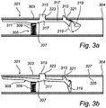
- safety post 301 has a tubular member 303 and a locking device 305.
- the locking device 305 comprises a lever 307, and a spring device 309 connected to the lever 307 at a spring seat 311 thereof.
- the lever comprises a lock protrusion 313 extending through a hole 321 in the wall of the tubular member 303, and a release protrusion 315 extending through another hole 323 of the wall.
- the lever has an elongate major portion 317 and an end portion 319.
- the major difference from the other embodiment is the end portion 319, which before mounting of the locking device 305 into the tubular member 303 is in a first position, where it is approximately aligned with or extends at an angle to the major portion 317.
- the end portion 319 is (further) bent in relation to the major portion 317 into a second position, which is shown by dashed lines in Fig. 3a .
- the lock protrusion 313 must be aligned with the hole 321 of the wall of the tubular member 303.
- each protrusion 313, 315 extends through its respective hole 321, 323, and protrudes from the outer surface 327 of the tubular member 303.
- the end portion 319 extends approximately diametrically through the inner space of the tubular member 303. Then the end portion 319 is long enough to prevent the locking device from being removed from the tubular member 303.
- Fig. 3b where the locking device is in the release position, and yet the lock protrusion 313 is not retracted inside of the inner surface 325 of the wall of the tubular member 303. Even if the release protrusion 315 would be pushed to a position inside of the inner surface 325 the lock protrusion 313 would remain extending into the hole 321 to an extent.
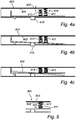
- FIGs. 4a-4c Further embodiments are shown in Figs. 4a-4c, and Fig. 5 .
- a more complex spring device can be used instead of or in conjunction with the previously described embodiments of the locking device.
- the spring device 409 comprises two springs, while the rest of the safety post is similar to the first embodiment above.
- a basic spring 411 of the spring device 409 corresponds to the spring described in the embodiments above, and an auxiliary spring 413 is added.
- the auxiliary spring 413 In the locking position of Fig. 4a the auxiliary spring 413 does not reach the inner surface 405 of the tubular member 403, but there is a gap 407 between the end of the spring and the inner surface 405.
- the auxiliary spring 413 In the release position of Fig. 4b the auxiliary spring 413 has made contact with the inner surface 405.
- a lever 420 lacking of the angled end portion can be used, as shown by dashed lines in Fig. 4c .
- the auxiliary spring 413 alone provides for the two-step function.
- the first operation step will correspond to what has been described above, while the second operation step is defined by the auxiliary counter force generated by the auxiliary spring 413 from the moment when it reaches the inner surface 405 of the tubular member 403.
- Fig. 5 an alternative spring device 509 is shown. It has a single spring but the spring consists of a primary spring section 511 and a secondary spring section, which has a larger spring constant than the first spring section 511.
- the spring sections 511, 513 are connected in series.
- the primary spring section is actuated providing a first spring force.
- the primary spring section becomes fully compressed during the first operation step. Consequently, during the second operation step the secondary spring section is actuated providing an increased spring force.
- This spring device can be used as a substitute for any one of the spring devices described above.
Landscapes
- Engineering & Computer Science (AREA)
- Architecture (AREA)
- Mechanical Engineering (AREA)
- Civil Engineering (AREA)
- Structural Engineering (AREA)
- General Engineering & Computer Science (AREA)
- Mutual Connection Of Rods And Tubes (AREA)
- Quick-Acting Or Multi-Walled Pipe Joints (AREA)
- Piles And Underground Anchors (AREA)
- Fuses (AREA)
Claims (9)
- Sicherheitspfosten (101), der ein längliches Rohrelement (103,303,403) umfasst und eine Verriegelungsvorrichtung (105), die im Rohrelement an einem ersten Ende (104) davon angeordnet ist und die angeordnet ist, in einem Pfostenhalter (201) aufgenommen zu sein, wobei die Verriegelungsvorrichtung einen Hebel (107) und eine Vorspannfedervorrichtung (109) beinhaltet, die den Hebel gegen eine innere Fläche (131) der Wand des Rohrelements vorspannt, wobei der Hebel einen Verriegelungsvorsprung (113,313) aufweist, der sich durch den Abschnitt einer ersten Öffnung (125) der Wand und von einer äußeren Fläche (129) der Wand erstreckt, und einen Freigabevorsprung (115), der sich durch den Abschnitt einer zweiten Öffnung (127) der Wand und von der äußeren Fläche (129) erstreckt, wobei der Freigabevorsprung (115) in einem Abstand vom Verriegelungsvorsprung (113,313) und weiter vom ersten Ende als der Verriegelungsvorsprung angeordnet ist, wobei der Verriegelungsvorsprung durch Betätigen des Freigabevorsprungs in eine Gegenvorspannrichtung in eine Freigabeposition innerhalb der äußeren Fläche des Rohrelements zurückziehbar ist, wobei der Freigabevorsprung (115) eine Stützfläche (116) aufweist, die angeordnet ist, um den Sicherheitspfosten gegen eine Stützfläche des Pfostenhalters zu stützen, wobei der Freigabevorsprung (115) so auf den Verriegelungsvorsprung (113,313) bezogen ist, dass der Freigabevorsprung in der Freigabeposition noch von der äußeren Fläche (129) vorsteht, wobei der Hebel (107) so angeordnet ist, dass der Freigabevorsprung in einer zwei Schritte umfassenden Betätigung betreibbar ist, wobei die Freigabeposition in einem ersten Betätigungsschritt erreicht wird, der eine erste auf den Freigabevorsprung aufgebrachte Betätigungskraft erfordert, und wobei eine nicht vorstehende Position des Freigabevorsprungs durch eine weitere Betätigung des Freigabevorsprungs in die Gegenvorspannrichtung erhalten wird, in einem zweiten Betätigungsschritt, der eine zweite, höhere Betätigungskraft erfordert, wobei der Hebel einen ersten Schwenkabschnitt (121) aufweist, um den der Hebel angeordnet ist, während des ersten Betätigungsschritts zu schwenken, wobei der Hebel angeordnet ist, zuerst um den ersten Abschnitt zu schwenken, bis das äußerste Ende des Endabschnitts die innere Fläche der Wand des Rohrelements erreicht, und einen zweiten Schwenkabschnitt (123), um den der Hebel angeordnet ist, während des zweiten Betätigungsschritts zu schwenken, und wobei der Hebel einen länglichen Hauptabschnitt (117) aufweist, der sich im Wesentlichen in Längsrichtung des Rohrelements erstreckt, der den ersten Schwenkabschnitt umfasst und mit dem die Vorsprünge verbunden sind, und einen länglichen Endabschnitt (119), der mit dem Hauptabschnitt in einem Winkel damit verbunden ist und der den zweiten Schwenkabschnitt umfasst.
- Sicherheitspfosten nach Anspruch 1, wobei der Hebel (107) so aufgehängt ist, dass während des ersten Schrittes die erste Betätigungskraft und eine entgegenwirkende Kraft, die von der Vorspannfedervorrichtung (109) erzeugt wird, auf Drehmomentarme wirken, die ein erstes Längenverhältnis aufweisen, und dass während des zweiten Betätigungsschritts die zweite Betätigungskraft und eine entgegenwirkende Kraft, die von der Vorspannfedervorrichtung erzeugt wird, auf Drehmomentarme wirken, die ein zweites Längenverhältnis aufweisen, das kleiner ist als das erste Längenverhältnis.
- Sicherheitspfosten nach Anspruch 1 oder 2, wobei der erste (121) und der zweite (123) Schwenkabschnitt auf verschiedenen Seiten des Freigabevorsprungs (115) gebildet sind.
- Sicherheitspfosten nach einem der Ansprüche 1-3, wobei der erste (121) und der zweite (123) Schwenkabschnitt an gegenüberliegenden Enden des Hebels gebildet sind.
- Sicherheitspfosten nach einem der Ansprüche 1-4, wobei der Endabschnitt (119) angeordnet ist, um sich vor dem Montieren der Verriegelungsvorrichtung im Rohrelement, bezogen auf den Hauptabschnitt (117), in einer ersten Position zu befinden, und um, bezogen auf den Hauptabschnitt, in eine zweite Position gebogen zu werden, nachdem der Hebel in das Rohrelement eingeführt und der Verriegelungsvorsprung auf den zweiten Öffnungsabschnitt ausgerichtet wurde, wobei der Endabschnitt (119) lang genug ist, um zu verhindern, dass der Verriegelungsvorsprung in eine Position innerhalb der inneren Fläche zurückgezogen wird.
- Sicherheitspfosten nach einem der Ansprüche 1-5, wobei die Federkonstante der Vorspannfedervorrichtung (109) während des zweiten Schritts größer ist als während des ersten Schritts.
- Sicherheitspfosten nach Anspruch 6, wobei die Vorspannfedervorrichtung ein primäres Federelement (511) umfasst, das das Vorspannen bereitstellt, und ein sekundäres Federelement (513), das während des zweiten Betätigungsschritts gemeinsam mit dem primären Federelement in Betrieb ist.
- Sicherheitspfosten nach Anspruch 6 oder 7, wobei die Vorspannfedervorrichtung mindestens eine Feder (509) umfasst, die einen primären Federabschnitt und einen sekundären Federabschnitt aufweist, der mit dem ersten Federabschnitt in Reihe verbunden ist und der eine größere Federkonstante aufweist als der erste Federabschnitt.
- Sicherheitspfosten nach einem der vorhergehenden Ansprüche, wobei der Verriegelungsvorsprung (113,313) eine schräge Rastfläche (114) aufweist.
Priority Applications (10)
| Application Number | Priority Date | Filing Date | Title |
|---|---|---|---|
| EP06100777.9A EP1820920B1 (de) | 2006-01-24 | 2006-01-24 | Sicherheitspfosten |
| JP2008552265A JP4977148B2 (ja) | 2006-01-24 | 2007-01-24 | 安全杭 |
| CN2007800033573A CN101375009B (zh) | 2006-01-24 | 2007-01-24 | 安全柱 |
| US12/087,728 US8246267B2 (en) | 2006-01-24 | 2007-01-24 | Safety post |
| PCT/SE2007/000062 WO2007086795A1 (en) | 2006-01-24 | 2007-01-24 | Safety post |
| KR1020087020567A KR20090003188A (ko) | 2006-01-24 | 2007-01-24 | 안전 포스트 |
| AU2007207899A AU2007207899B2 (en) | 2006-01-24 | 2007-01-24 | Safety post |
| NZ569659A NZ569659A (en) | 2006-01-24 | 2007-01-24 | Safety post |
| CA002636360A CA2636360A1 (en) | 2006-01-24 | 2007-01-24 | Safety post |
| NO20082990A NO20082990L (no) | 2006-01-24 | 2008-07-02 | Sikkerhetsstang |
Applications Claiming Priority (1)
| Application Number | Priority Date | Filing Date | Title |
|---|---|---|---|
| EP06100777.9A EP1820920B1 (de) | 2006-01-24 | 2006-01-24 | Sicherheitspfosten |
Publications (2)
| Publication Number | Publication Date |
|---|---|
| EP1820920A1 EP1820920A1 (de) | 2007-08-22 |
| EP1820920B1 true EP1820920B1 (de) | 2017-10-18 |
Family
ID=36577185
Family Applications (1)
| Application Number | Title | Priority Date | Filing Date |
|---|---|---|---|
| EP06100777.9A Not-in-force EP1820920B1 (de) | 2006-01-24 | 2006-01-24 | Sicherheitspfosten |
Country Status (10)
| Country | Link |
|---|---|
| US (1) | US8246267B2 (de) |
| EP (1) | EP1820920B1 (de) |
| JP (1) | JP4977148B2 (de) |
| KR (1) | KR20090003188A (de) |
| CN (1) | CN101375009B (de) |
| AU (1) | AU2007207899B2 (de) |
| CA (1) | CA2636360A1 (de) |
| NO (1) | NO20082990L (de) |
| NZ (1) | NZ569659A (de) |
| WO (1) | WO2007086795A1 (de) |
Families Citing this family (13)
| Publication number | Priority date | Publication date | Assignee | Title |
|---|---|---|---|---|
| GB2461599B (en) * | 2008-07-09 | 2012-11-07 | Combisafe Int Ab | Post assembly |
| DE102009014612B3 (de) * | 2009-03-24 | 2010-12-02 | Doka Industrie Gmbh | Steher für eine Absturzsicherung |
| EP2464802B1 (de) | 2009-08-10 | 2018-01-24 | Combisafe International Aktiebolag | Kantenschutzsystem |
| CN102991560B (zh) * | 2011-09-08 | 2016-01-13 | 明门香港股份有限公司 | 婴儿车架及其小腿靠装置 |
| CN105019674B (zh) * | 2015-07-27 | 2017-11-24 | 江苏溧阳建设集团有限公司 | 一种安全顶 |
| CN106890689A (zh) * | 2017-02-23 | 2017-06-27 | 苏州欣祥本机械科技有限公司 | 一种用于高中化学实验的可折叠铁架台 |
| CN107558120A (zh) * | 2017-09-27 | 2018-01-09 | 青岛河澄知识产权有限公司 | 一种架体折叠式晾衣架 |
| CN108224002A (zh) * | 2018-03-07 | 2018-06-29 | 海宁瑞峰祥宇影视制作有限公司 | 摄影支架中杆体一与杆体二的连接机构 |
| CN208886291U (zh) * | 2018-10-18 | 2019-05-21 | 京东方科技集团股份有限公司 | 用于显示设备的支架组件和具有其的显示设备 |
| SE543825C2 (en) * | 2020-01-28 | 2021-08-03 | Nordic Road Safety Ab | A post unit for safety road barriers, a safety road barrier, and a method for assembling the post unit |
| CN111959826A (zh) * | 2020-08-12 | 2020-11-20 | 南京林业大学 | 一种具有快速在轨组装功能的空间桁架结构连接件 |
| US12025177B2 (en) | 2020-10-27 | 2024-07-02 | Robert Varney | Universal coupling for hollow carbon fiber composite structures |
| TWI808753B (zh) * | 2022-05-10 | 2023-07-11 | 梁奇銓 | 管件組合結構 |
Family Cites Families (14)
| Publication number | Priority date | Publication date | Assignee | Title |
|---|---|---|---|---|
| JPH01152892A (ja) * | 1987-12-10 | 1989-06-15 | Shibasoku:Kk | Pal方式での色信号をデジタル処理で作成する方法 |
| KR950011365B1 (ko) * | 1991-06-24 | 1995-10-02 | 아루 잉꼬 가부시끼가이샤 | 발판용 세움틀 |
| JPH0724521Y2 (ja) * | 1992-08-17 | 1995-06-05 | アサヒ産業株式会社 | パイプジョイント |
| JP3477659B2 (ja) * | 1993-03-31 | 2003-12-10 | 株式会社石井鐵工所 | 連結装置 |
| JP2653975B2 (ja) * | 1994-04-19 | 1997-09-17 | アサヒ産業株式会社 | パイプジョイント |
| JPH07292958A (ja) * | 1994-04-28 | 1995-11-07 | Meiko Kinzoku Kogyo Kk | 足場用建枠のジョイント |
| US5427130A (en) * | 1994-10-11 | 1995-06-27 | Yang; Teng-Yen | Parasol structure |
| JPH0913661A (ja) * | 1995-06-28 | 1997-01-14 | Ota Seisakusho:Kk | パイプジョイント |
| US5778914A (en) * | 1996-03-28 | 1998-07-14 | Trani; Armando P. | Portable telescopic weighted walking pole |
| JPH09302922A (ja) * | 1996-05-16 | 1997-11-25 | Daiyu Tekko Kk | パイプジョイント |
| JPH1082171A (ja) * | 1996-09-05 | 1998-03-31 | Asahi Sangyo Kk | パイプジョイント |
| JP3223423B2 (ja) * | 1997-11-19 | 2001-10-29 | 長谷川工業株式会社 | 折畳み式作業台 |
| JP3306001B2 (ja) * | 1998-05-06 | 2002-07-24 | アルインコ株式会社 | 足場建枠用連結ピン |
| JP3443035B2 (ja) * | 1999-05-18 | 2003-09-02 | アルインコ株式会社 | 足場建枠用連結ピン |
-
2006
- 2006-01-24 EP EP06100777.9A patent/EP1820920B1/de not_active Not-in-force
-
2007
- 2007-01-24 WO PCT/SE2007/000062 patent/WO2007086795A1/en active Application Filing
- 2007-01-24 CA CA002636360A patent/CA2636360A1/en not_active Abandoned
- 2007-01-24 JP JP2008552265A patent/JP4977148B2/ja not_active Expired - Fee Related
- 2007-01-24 AU AU2007207899A patent/AU2007207899B2/en not_active Expired - Fee Related
- 2007-01-24 CN CN2007800033573A patent/CN101375009B/zh not_active Expired - Fee Related
- 2007-01-24 KR KR1020087020567A patent/KR20090003188A/ko not_active Application Discontinuation
- 2007-01-24 US US12/087,728 patent/US8246267B2/en active Active
- 2007-01-24 NZ NZ569659A patent/NZ569659A/en not_active IP Right Cessation
-
2008
- 2008-07-02 NO NO20082990A patent/NO20082990L/no not_active Application Discontinuation
Non-Patent Citations (1)
| Title |
|---|
| None * |
Also Published As
| Publication number | Publication date |
|---|---|
| JP2009524784A (ja) | 2009-07-02 |
| CA2636360A1 (en) | 2007-08-02 |
| JP4977148B2 (ja) | 2012-07-18 |
| NO20082990L (no) | 2008-10-21 |
| NZ569659A (en) | 2010-03-26 |
| US8246267B2 (en) | 2012-08-21 |
| CN101375009A (zh) | 2009-02-25 |
| US20090085022A1 (en) | 2009-04-02 |
| CN101375009B (zh) | 2012-10-31 |
| KR20090003188A (ko) | 2009-01-09 |
| WO2007086795A1 (en) | 2007-08-02 |
| EP1820920A1 (de) | 2007-08-22 |
| AU2007207899A1 (en) | 2007-08-02 |
| AU2007207899B2 (en) | 2012-07-19 |
Similar Documents
| Publication | Publication Date | Title |
|---|---|---|
| EP1820920B1 (de) | Sicherheitspfosten | |
| EP3042019B1 (de) | Einstellbare leitern, leiterkomponenten und entsprechende verfahren | |
| EP1921226B1 (de) | Stützvorrichtung | |
| US11306497B2 (en) | Support post | |
| JP5264008B1 (ja) | 仮設足場用の連結装置 | |
| EP1731830B1 (de) | Befestigungseinrichtung für ein Einbaugerät | |
| EP2356930A2 (de) | Scharnieranordnung | |
| EP1972737A2 (de) | Gerüstanordnung | |
| JP2024053567A (ja) | 足場における楔緊結装置 | |
| JP4831332B2 (ja) | 突張支柱 | |
| EP0921254B1 (de) | Baustütze | |
| KR102449036B1 (ko) | 작업플레이트를 갖는 작업사다리에서 안전난간의 높낮이 조절용 클램프 | |
| KR101634297B1 (ko) | 차량용 시트 트랙 록킹장치 | |
| JP3443035B2 (ja) | 足場建枠用連結ピン | |
| EP3651559A1 (de) | Klammervorrichtung | |
| AU691055B2 (en) | A locking mechanism | |
| JPH0913661A (ja) | パイプジョイント | |
| KR200382631Y1 (ko) | 높이조절이 가능한 사다리 | |
| JPH1055481A (ja) | 自動販売機脚部用係合部材および転倒防止部材 | |
| JP2527504Y2 (ja) | 安全手摺のストッパー機構 | |
| JPH07289379A (ja) | 陳列装置用伸縮支柱の係止装置 | |
| WO2010063772A1 (en) | Reinforced collapsible ladder | |
| EP2907943A1 (de) | Verriegelung einer Kanalsperre | |
| JPH07230712A (ja) | 照明器具の反射板取付け構造 | |
| JPH0547298U (ja) | 伸縮梯子の固定装置 |
Legal Events
| Date | Code | Title | Description |
|---|---|---|---|
| PUAI | Public reference made under article 153(3) epc to a published international application that has entered the european phase |
Free format text: ORIGINAL CODE: 0009012 |
|
| AK | Designated contracting states |
Kind code of ref document: A1 Designated state(s): AT BE BG CH CY CZ DE DK EE ES FI FR GB GR HU IE IS IT LI LT LU LV MC NL PL PT RO SE SI SK TR |
|
| AX | Request for extension of the european patent |
Extension state: AL BA HR MK YU |
|
| 17P | Request for examination filed |
Effective date: 20070906 |
|
| 17Q | First examination report despatched |
Effective date: 20071009 |
|
| AKX | Designation fees paid |
Designated state(s): AT BE BG CH CY CZ DE DK EE ES FI FR GB GR HU IE IS IT LI LT LU LV MC NL PL PT RO SE SI SK TR |
|
| STAA | Information on the status of an ep patent application or granted ep patent |
Free format text: STATUS: EXAMINATION IS IN PROGRESS |
|
| GRAP | Despatch of communication of intention to grant a patent |
Free format text: ORIGINAL CODE: EPIDOSNIGR1 |
|
| STAA | Information on the status of an ep patent application or granted ep patent |
Free format text: STATUS: GRANT OF PATENT IS INTENDED |
|
| INTG | Intention to grant announced |
Effective date: 20170220 |
|
| GRAS | Grant fee paid |
Free format text: ORIGINAL CODE: EPIDOSNIGR3 |
|
| GRAJ | Information related to disapproval of communication of intention to grant by the applicant or resumption of examination proceedings by the epo deleted |
Free format text: ORIGINAL CODE: EPIDOSDIGR1 |
|
| GRAL | Information related to payment of fee for publishing/printing deleted |
Free format text: ORIGINAL CODE: EPIDOSDIGR3 |
|
| STAA | Information on the status of an ep patent application or granted ep patent |
Free format text: STATUS: EXAMINATION IS IN PROGRESS |
|
| GRAP | Despatch of communication of intention to grant a patent |
Free format text: ORIGINAL CODE: EPIDOSNIGR1 |
|
| STAA | Information on the status of an ep patent application or granted ep patent |
Free format text: STATUS: GRANT OF PATENT IS INTENDED |
|
| INTC | Intention to grant announced (deleted) | ||
| INTG | Intention to grant announced |
Effective date: 20170719 |
|
| GRAA | (expected) grant |
Free format text: ORIGINAL CODE: 0009210 |
|
| STAA | Information on the status of an ep patent application or granted ep patent |
Free format text: STATUS: THE PATENT HAS BEEN GRANTED |
|
| AK | Designated contracting states |
Kind code of ref document: B1 Designated state(s): AT BE BG CH CY CZ DE DK EE ES FI FR GB GR HU IE IS IT LI LT LU LV MC NL PL PT RO SE SI SK TR |
|
| REG | Reference to a national code |
Ref country code: GB Ref legal event code: FG4D |
|
| REG | Reference to a national code |
Ref country code: CH Ref legal event code: EP |
|
| REG | Reference to a national code |
Ref country code: AT Ref legal event code: REF Ref document number: 938089 Country of ref document: AT Kind code of ref document: T Effective date: 20171115 Ref country code: IE Ref legal event code: FG4D |
|
| REG | Reference to a national code |
Ref country code: DE Ref legal event code: R096 Ref document number: 602006053870 Country of ref document: DE |
|
| REG | Reference to a national code |
Ref country code: SE Ref legal event code: TRGR |
|
| REG | Reference to a national code |
Ref country code: FR Ref legal event code: PLFP Year of fee payment: 13 |
|
| REG | Reference to a national code |
Ref country code: NL Ref legal event code: MP Effective date: 20171018 |
|
| REG | Reference to a national code |
Ref country code: LT Ref legal event code: MG4D |
|
| REG | Reference to a national code |
Ref country code: AT Ref legal event code: MK05 Ref document number: 938089 Country of ref document: AT Kind code of ref document: T Effective date: 20171018 |
|
| PG25 | Lapsed in a contracting state [announced via postgrant information from national office to epo] |
Ref country code: NL Free format text: LAPSE BECAUSE OF FAILURE TO SUBMIT A TRANSLATION OF THE DESCRIPTION OR TO PAY THE FEE WITHIN THE PRESCRIBED TIME-LIMIT Effective date: 20171018 |
|
| PG25 | Lapsed in a contracting state [announced via postgrant information from national office to epo] |
Ref country code: LT Free format text: LAPSE BECAUSE OF FAILURE TO SUBMIT A TRANSLATION OF THE DESCRIPTION OR TO PAY THE FEE WITHIN THE PRESCRIBED TIME-LIMIT Effective date: 20171018 Ref country code: ES Free format text: LAPSE BECAUSE OF FAILURE TO SUBMIT A TRANSLATION OF THE DESCRIPTION OR TO PAY THE FEE WITHIN THE PRESCRIBED TIME-LIMIT Effective date: 20171018 Ref country code: FI Free format text: LAPSE BECAUSE OF FAILURE TO SUBMIT A TRANSLATION OF THE DESCRIPTION OR TO PAY THE FEE WITHIN THE PRESCRIBED TIME-LIMIT Effective date: 20171018 |
|
| PG25 | Lapsed in a contracting state [announced via postgrant information from national office to epo] |
Ref country code: BG Free format text: LAPSE BECAUSE OF FAILURE TO SUBMIT A TRANSLATION OF THE DESCRIPTION OR TO PAY THE FEE WITHIN THE PRESCRIBED TIME-LIMIT Effective date: 20180118 Ref country code: LV Free format text: LAPSE BECAUSE OF FAILURE TO SUBMIT A TRANSLATION OF THE DESCRIPTION OR TO PAY THE FEE WITHIN THE PRESCRIBED TIME-LIMIT Effective date: 20171018 Ref country code: AT Free format text: LAPSE BECAUSE OF FAILURE TO SUBMIT A TRANSLATION OF THE DESCRIPTION OR TO PAY THE FEE WITHIN THE PRESCRIBED TIME-LIMIT Effective date: 20171018 Ref country code: GR Free format text: LAPSE BECAUSE OF FAILURE TO SUBMIT A TRANSLATION OF THE DESCRIPTION OR TO PAY THE FEE WITHIN THE PRESCRIBED TIME-LIMIT Effective date: 20180119 Ref country code: IS Free format text: LAPSE BECAUSE OF FAILURE TO SUBMIT A TRANSLATION OF THE DESCRIPTION OR TO PAY THE FEE WITHIN THE PRESCRIBED TIME-LIMIT Effective date: 20180218 |
|
| PGFP | Annual fee paid to national office [announced via postgrant information from national office to epo] |
Ref country code: SE Payment date: 20180129 Year of fee payment: 13 |
|
| REG | Reference to a national code |
Ref country code: DE Ref legal event code: R097 Ref document number: 602006053870 Country of ref document: DE |
|
| PG25 | Lapsed in a contracting state [announced via postgrant information from national office to epo] |
Ref country code: EE Free format text: LAPSE BECAUSE OF FAILURE TO SUBMIT A TRANSLATION OF THE DESCRIPTION OR TO PAY THE FEE WITHIN THE PRESCRIBED TIME-LIMIT Effective date: 20171018 Ref country code: DK Free format text: LAPSE BECAUSE OF FAILURE TO SUBMIT A TRANSLATION OF THE DESCRIPTION OR TO PAY THE FEE WITHIN THE PRESCRIBED TIME-LIMIT Effective date: 20171018 Ref country code: SK Free format text: LAPSE BECAUSE OF FAILURE TO SUBMIT A TRANSLATION OF THE DESCRIPTION OR TO PAY THE FEE WITHIN THE PRESCRIBED TIME-LIMIT Effective date: 20171018 Ref country code: CZ Free format text: LAPSE BECAUSE OF FAILURE TO SUBMIT A TRANSLATION OF THE DESCRIPTION OR TO PAY THE FEE WITHIN THE PRESCRIBED TIME-LIMIT Effective date: 20171018 |
|
| PLBE | No opposition filed within time limit |
Free format text: ORIGINAL CODE: 0009261 |
|
| STAA | Information on the status of an ep patent application or granted ep patent |
Free format text: STATUS: NO OPPOSITION FILED WITHIN TIME LIMIT |
|
| PG25 | Lapsed in a contracting state [announced via postgrant information from national office to epo] |
Ref country code: PL Free format text: LAPSE BECAUSE OF FAILURE TO SUBMIT A TRANSLATION OF THE DESCRIPTION OR TO PAY THE FEE WITHIN THE PRESCRIBED TIME-LIMIT Effective date: 20171018 Ref country code: RO Free format text: LAPSE BECAUSE OF FAILURE TO SUBMIT A TRANSLATION OF THE DESCRIPTION OR TO PAY THE FEE WITHIN THE PRESCRIBED TIME-LIMIT Effective date: 20171018 Ref country code: IT Free format text: LAPSE BECAUSE OF FAILURE TO SUBMIT A TRANSLATION OF THE DESCRIPTION OR TO PAY THE FEE WITHIN THE PRESCRIBED TIME-LIMIT Effective date: 20171018 |
|
| REG | Reference to a national code |
Ref country code: CH Ref legal event code: PL |
|
| 26N | No opposition filed |
Effective date: 20180719 |
|
| PG25 | Lapsed in a contracting state [announced via postgrant information from national office to epo] |
Ref country code: LU Free format text: LAPSE BECAUSE OF NON-PAYMENT OF DUE FEES Effective date: 20180124 |
|
| REG | Reference to a national code |
Ref country code: IE Ref legal event code: MM4A |
|
| REG | Reference to a national code |
Ref country code: BE Ref legal event code: MM Effective date: 20180131 |
|
| PG25 | Lapsed in a contracting state [announced via postgrant information from national office to epo] |
Ref country code: BE Free format text: LAPSE BECAUSE OF NON-PAYMENT OF DUE FEES Effective date: 20180131 Ref country code: CH Free format text: LAPSE BECAUSE OF NON-PAYMENT OF DUE FEES Effective date: 20180131 Ref country code: SI Free format text: LAPSE BECAUSE OF FAILURE TO SUBMIT A TRANSLATION OF THE DESCRIPTION OR TO PAY THE FEE WITHIN THE PRESCRIBED TIME-LIMIT Effective date: 20171018 Ref country code: LI Free format text: LAPSE BECAUSE OF NON-PAYMENT OF DUE FEES Effective date: 20180131 |
|
| PG25 | Lapsed in a contracting state [announced via postgrant information from national office to epo] |
Ref country code: IE Free format text: LAPSE BECAUSE OF NON-PAYMENT OF DUE FEES Effective date: 20180124 |
|
| PGFP | Annual fee paid to national office [announced via postgrant information from national office to epo] |
Ref country code: GB Payment date: 20190130 Year of fee payment: 14 Ref country code: FR Payment date: 20190128 Year of fee payment: 14 |
|
| PG25 | Lapsed in a contracting state [announced via postgrant information from national office to epo] |
Ref country code: MC Free format text: LAPSE BECAUSE OF FAILURE TO SUBMIT A TRANSLATION OF THE DESCRIPTION OR TO PAY THE FEE WITHIN THE PRESCRIBED TIME-LIMIT Effective date: 20171018 |
|
| PG25 | Lapsed in a contracting state [announced via postgrant information from national office to epo] |
Ref country code: SE Free format text: LAPSE BECAUSE OF NON-PAYMENT OF DUE FEES Effective date: 20190125 |
|
| PG25 | Lapsed in a contracting state [announced via postgrant information from national office to epo] |
Ref country code: TR Free format text: LAPSE BECAUSE OF FAILURE TO SUBMIT A TRANSLATION OF THE DESCRIPTION OR TO PAY THE FEE WITHIN THE PRESCRIBED TIME-LIMIT Effective date: 20171018 |
|
| PGFP | Annual fee paid to national office [announced via postgrant information from national office to epo] |
Ref country code: DE Payment date: 20200131 Year of fee payment: 15 |
|
| PG25 | Lapsed in a contracting state [announced via postgrant information from national office to epo] |
Ref country code: PT Free format text: LAPSE BECAUSE OF FAILURE TO SUBMIT A TRANSLATION OF THE DESCRIPTION OR TO PAY THE FEE WITHIN THE PRESCRIBED TIME-LIMIT Effective date: 20171018 Ref country code: HU Free format text: LAPSE BECAUSE OF FAILURE TO SUBMIT A TRANSLATION OF THE DESCRIPTION OR TO PAY THE FEE WITHIN THE PRESCRIBED TIME-LIMIT; INVALID AB INITIO Effective date: 20060124 |
|
| PG25 | Lapsed in a contracting state [announced via postgrant information from national office to epo] |
Ref country code: CY Free format text: LAPSE BECAUSE OF FAILURE TO SUBMIT A TRANSLATION OF THE DESCRIPTION OR TO PAY THE FEE WITHIN THE PRESCRIBED TIME-LIMIT Effective date: 20171018 |
|
| GBPC | Gb: european patent ceased through non-payment of renewal fee |
Effective date: 20200124 |
|
| PG25 | Lapsed in a contracting state [announced via postgrant information from national office to epo] |
Ref country code: FR Free format text: LAPSE BECAUSE OF NON-PAYMENT OF DUE FEES Effective date: 20200131 Ref country code: GB Free format text: LAPSE BECAUSE OF NON-PAYMENT OF DUE FEES Effective date: 20200124 |
|
| REG | Reference to a national code |
Ref country code: DE Ref legal event code: R119 Ref document number: 602006053870 Country of ref document: DE |
|
| PG25 | Lapsed in a contracting state [announced via postgrant information from national office to epo] |
Ref country code: DE Free format text: LAPSE BECAUSE OF NON-PAYMENT OF DUE FEES Effective date: 20210803 |