EP1819256B1 - Schubladenführungseinrichtung - Google Patents
Schubladenführungseinrichtung Download PDFInfo
- Publication number
- EP1819256B1 EP1819256B1 EP05810975.2A EP05810975A EP1819256B1 EP 1819256 B1 EP1819256 B1 EP 1819256B1 EP 05810975 A EP05810975 A EP 05810975A EP 1819256 B1 EP1819256 B1 EP 1819256B1
- Authority
- EP
- European Patent Office
- Prior art keywords
- drawer
- rail
- stop
- guiding device
- rails
- Prior art date
- Legal status (The legal status is an assumption and is not a legal conclusion. Google has not performed a legal analysis and makes no representation as to the accuracy of the status listed.)
- Expired - Lifetime
Links
Images



Classifications
-
- A—HUMAN NECESSITIES
- A47—FURNITURE; DOMESTIC ARTICLES OR APPLIANCES; COFFEE MILLS; SPICE MILLS; SUCTION CLEANERS IN GENERAL
- A47B—TABLES; DESKS; OFFICE FURNITURE; CABINETS; DRAWERS; GENERAL DETAILS OF FURNITURE
- A47B88/00—Drawers for tables, cabinets or like furniture; Guides for drawers
- A47B88/40—Sliding drawers; Slides or guides therefor
- A47B88/453—Actuated drawers
- A47B88/46—Actuated drawers operated by mechanically-stored energy, e.g. by springs
- A47B88/467—Actuated drawers operated by mechanically-stored energy, e.g. by springs self-closing
-
- A—HUMAN NECESSITIES
- A47—FURNITURE; DOMESTIC ARTICLES OR APPLIANCES; COFFEE MILLS; SPICE MILLS; SUCTION CLEANERS IN GENERAL
- A47B—TABLES; DESKS; OFFICE FURNITURE; CABINETS; DRAWERS; GENERAL DETAILS OF FURNITURE
- A47B2210/00—General construction of drawers, guides and guide devices
- A47B2210/0002—Guide construction for drawers
- A47B2210/001—Guide construction for drawers having a roller on the intermediate drawer rail, between the upper and lower rail
-
- A—HUMAN NECESSITIES
- A47—FURNITURE; DOMESTIC ARTICLES OR APPLIANCES; COFFEE MILLS; SPICE MILLS; SUCTION CLEANERS IN GENERAL
- A47B—TABLES; DESKS; OFFICE FURNITURE; CABINETS; DRAWERS; GENERAL DETAILS OF FURNITURE
- A47B2210/00—General construction of drawers, guides and guide devices
- A47B2210/0002—Guide construction for drawers
- A47B2210/0064—Guide sequencing or synchronisation
- A47B2210/007—Three slide synchronisation
Definitions
- the present invention relates to a drawer guide device according to the preamble of claim 1.
- a drawer guide device in which a catchment device is effective on a section.
- This retraction device comprises a spring to bias the movable furniture part in the closed position.
- the spring of the retraction device is too weak to overcome the sliding friction between a roller on a central rail and another rail. Therefore, it may happen that the middle rail does not run exactly half way through the rail mounted on the drawer and misalignments occur.
- the EP 1 161 164 describes a Auszieh arrangementsgarnitur in which the motion damper is mounted on the pull-out rail and the free end is coupled to a slide seated on this rail. When retracting this slide abuts against a mounting rail or a center rail, whereby the closing movement is damped. However, a forced synchronization of the movement of the rails, for example for correcting an inclined drawer, is not shown.
- the DE 203 07 757 U1 discloses a pull-out guide for drawers in which three rails are slidably supported by rollers on each other. Two carriages are provided, which are coupled together for positive guidance via cables. The cables should be used to prevent the rollers from slipping along the rail.
- the drawer guiding device comprises means for forcibly synchronizing the running movement of the rails movable relative to one another, so as to ensure that the middle rail runs exactly half way as the extendable first rail.
- the means for synchronizing comprise a stop which is effective before or at the beginning of the section of the collection device.
- the collection device can be used to additionally achieve a precise position of the rails at the beginning of the effectiveness of the collection device, wherein the closing movement of the drawer can be used for a possible correction movement. If no correction movement is required, the means for synchronizing the running movement of the rails can remain inactive and do not hinder the closing operation.
- the stop may be formed on one of the rails or fixed there.
- a roller is mounted on the middle guide rail, which rests against the first and third rail, thus coupling these rails with each other, wherein the middle guide rail is moved due to the roller at half the speed as the extendable first rail.
- At the middle Guide rail is preferably a stop fixed, which cooperates for synchronization with a counter-stop.
- the counter-stop can be formed on a driver of the collection device. The arrangement of the stop on the central guide rail, it is possible to make the stop acting in both directions, and thereby to be able to compensate for slippage both in the extension direction and against the extension direction.
- the collection device comprises on a driver a receptacle in which engages a coupled to the first rail activator.
- a drawer guide device 1 is shown as it is mounted on one side of a drawer to a fixed furniture body.
- a corresponding drawer guide device 1 may be provided on both sides of the drawer, wherein the right and left side of the drawer guide means 1 are constructed in mirror image.
- the left side of the drawer guide device 1 is shown without a centrally located drawer.
- the drawer guide device 1 comprises a first rail 2, which is connected to a pull-out drawer.
- the first rail 2 is coupled via a central guide rail 3 with a third rail 4, which is fixed to a furniture body.
- the rails 2 and 4 and the guide rail 3 are held on rolling and rolling elements 18, 20, 22, and 24 slidably together.
- the invention can also be used for drawer guide devices in which three or more than three rails 2, 3 and 4 are provided.
- a roller 5 is mounted, which rolls both on the rail 2 and on the rail 4, so that the middle guide rail 3 is moved at half the speed as the rail 2 relative to the stationary rail 4.
- a collection device 6 which cooperates with a web-shaped activator 7 to feed this over a partial distance in front of the closed position of the drawer into the furniture body.
- the collection device 6 comprises a driver 8 which can be coupled to the activator 7, wherein the activator 7 is fixed to the movable rail 2.
- the retracting device 6 comprises, on a housing 14, a curved guide 11 which is bent at one end section so that a driver 8 is moved along the curved guide 11 and is pivoted and parked on the curved section 12. In the parked position connected to the stationary driver 8 spring 13 is tensioned, wherein the spring 13 is fixed to the end remote from the driver 8 on the housing 14.
- a projecting stop 9 is formed on the central guide rail 3, which can be passed through an opening 15 on the housing 14 of the collection device and when closing can interact with the formed as a web-shaped driver activator 7.
- FIGS. 1A to 1C the drawer guide device 1 is shown in a closed position, in the rolling or rolling bodies 18, 20, 22 and 24, which may be held in a cage, abut corresponding stops 17, 19, 21 and 23 on the rails 2 and 4.
- the drawer is held by the force of the spring 13 in the closed position.
- FIGS. 3A to 3C the position of the drawer guide device 1 is shown, in which the activator 7 leaves the receptacle 16 on the driver 8.
- the driver 8 has been pivoted in the cam guide 11 on the section 12, being fixed by the pivoting of the driver 8 in a parking position in which the spring 13 remains taut. If there is no slippage between the rails 2, 3 and 4, the driver 8 enters the parking position, the stop 9 is contacted by the driver 8 with a counter-stop 10 at best, but not to a displacement due to the higher speed of the driver 8 opposite the stop 9 comes.
- the stopper 9 is rather moved through an opening 15 in the housing 14 of the collection device 6. When the guide rail 3 runs correctly, the stop 9 leaves the opening 15 in the housing 14, while the driver 8 with the counter-stop 10 remains in the parking position.
- the rail 2 can now be moved further in the open position, wherein the activator 7 a receptacle 16 at leaves the driver 8 and moves further to the left.
- the stopper 9 continues to move at half speed relative to the activator 7.
- FIGS. 5A to 5C the open position of the drawer guide device 1 is shown.
- the rolling elements 22 abut against an end stop 25, which limit the maximum Auszugsweg.
- Stop 9 and activator 7 are positioned offset from one another with respect to the original arrangement, wherein the stop 9 first abuts against the driver 8 in the region of the counter-stop 10 before the activator 7 has reached the receptacle 16. Due to the kinetic energy when closing the drawer, however, the required sliding friction for moving the rail 2 relative to the guide rail 3 and rail 4 can be easily overcome, so that the roller 5 is slipped over.
- the middle guide rail 3 is held stationary by the stop 9 a curve time, since the stop 9 abuts against the counter-stop 10 of the driver 8 and the driver 8 remains due to the tilted position in the parking position.
- the collection device 6 is activated, wherein the driver 8 is again moved along the cam guide 11 and is biased by the spring 13 of the drawer in the closed position ( FIGS. 8A to 8C ). Since the stop 9 moves only at half speed relative to the activator 7 and the driver 8, the two components move away from each other again.
- FIGS. 9A to 9C again the closed position of the drawer guide device 1 is shown, in which the rolling or rolling elements 18, 20, 22 and 24 abut against corresponding stops 17, 19, 21 and 23 on the rails 2 and 4.
- the spring 13 of the feeder 6 By the spring 13 of the feeder 6, the drawer is held in the closed position.
- damping or braking device is shown, which may be provided in particular in the region of the partial section, in which the retraction device 6 is effective.
- Corresponding damping devices are known and can additionally be mounted or coupled to the collection device 6.
- the means for forcibly synchronizing the running motion can be effective in both directions, wherein the synchronization can also take place in the position that in the FIGS. 3A to 3C is shown when the driver 8 comes with the counter-stop 10 to the stop 9 to the plant.
Landscapes
- Engineering & Computer Science (AREA)
- Mechanical Engineering (AREA)
- Drawers Of Furniture (AREA)
Description
- Die vorliegende Erfindung betrifft eine Schubladenführungseinrichtung nach dem Oberbegriff des Anspruches 1.
- Aus der
EP 391 221 - Die
EP 1 161 164 beschreibt eine Ausziehführungsgarnitur, bei der der Bewegungsdämpfer auf der Auszugsschiene befestigt ist und dessen freies Ende mit einem auf dieser Schiene sitzenden Schieber gekoppelt ist. Beim Einfahren stößt dieser Schieber gegen eine Tragschiene oder eine Mittelschiene, wodurch die Schließbewegung gedämpft wird. Eine zwangsweise Synchronisierung der Bewegung der Schienen, beispielsweise zur Korrektur einer schräg stehenden Schublade, ist jedoch nicht gezeigt. - In der
EP 1 393 654 ist eine Ausziehführungsgarnitur für Schubladen bekannt, bei der Laufwagen eingesetzt werden, auf denen mindestens zwei Schienen gegeneinander abrollen. Um einen Versatz der Laufwagen relativ zu den Schienen zu vermeiden, werden die Laufwagen zeitweilig arretiert und eine Freigabe erfolgt dann durch die Bewegung der Schienen. Diese Lösung ist jedoch mechanisch vergleichsweise aufwendig. - Die
DE 203 07 757 U1 offenbart eine Ausziehführungsgarnitur für Schubladen, bei der drei Schienen über Laufrollen verschiebbar aneinander gelagert sind. Dabei sind zwei Laufwagen vorgesehen, die für eine Zwangsführung über Seilzüge miteinander gekoppelt sind. Durch die Seilzüge soll vermieden werden, dass die Laufrollen entlang der Schiene verrutschen. - Es ist daher Aufgabe der vorliegenden Erfindung eine Schubladenführungseinrichtung zu schaffen, die ein sicheres Schließen eines Schubkastens gewährleistet und auftretender Schlupf korrigiert werden kann.
- Diese Aufgabe wird mit einer Schubladenführungseinrichtung mit den Merkmalen des Anspruches 1 gelöst.
- Erfindungsgemäß umfasst die Schubladenführungseinrichtung Mittel zum zwangsweisen Synchronisieren der Laufbewegung der relativ zueinander bewegbaren Schienen, so dass gewährleistet ist, dass die mittlere Schiene genau den halben Weg läuft wie die ausziehbare erste Schiene. Dadurch kann bei einem Auftreten von Schlupf zwischen einer an der mittleren Führungsschiene gelagerten Rolle und der ersten Schiene erreicht werden, dass durch die Mittel zum Synchronisieren eine gewünschte Ausrichtung des Schubkastens vorgenommen wird und ggfs. auch eine Schiefstellung des Schubkastens verhindert wird. Auch bei ruckartigen Bewegungen des Schubkastens, oder anderen Gründen für Schlupf wird somit eine Schiefstellung oder eine vom Möbelkorpus beabstandete Endlage des Schubkastens vermieden. Durch die Bauteile der Schubladenführungseinrichtung ist somit eine definierte Laufbewegung vorgegeben.
- Gemäß einer bevorzugten Ausgestaltung der Erfindung umfassen die Mittel zum Synchronisieren einen Anschlag, der vor oder an dem Beginn der Teilstrecke der Einzugsvorrichtung wirksam ist. Dadurch kann die Einzugsvorrichtung genutzt werden, um zusätzlich eine genaue Lage der Schienen am Beginn der Wirksamkeit der Einzugsvorrichtung zu erreichen, wobei die Schließbewegung der Schublade für eine mögliche Korrekturbewegung genutzt werden kann. Wird keine Korrekturbewegung benötigt, können die Mittel zum Synchronisieren der Laufbewegung der Schienen inaktiv bleiben und behindern den Schließvorgang nicht.
- Der Anschlag kann dabei an einer der Schienen ausgebildet sein oder dort festgelegt sein. Vorzugsweise ist an der mittleren Führungsschiene eine Rolle gelagert, die an der ersten und dritten Schiene anliegt, diese Schienen also miteinander koppelt, wobei die mittlere Führungsschiene aufgrund der Rolle mit der halben Geschwindigkeit wie die ausziehbare erste Schiene bewegt wird. An der mittleren Führungsschiene ist vorzugsweise ein Anschlag festgelegt, der zur Synchronisation mit einem Gegenanschlag zusammenwirkt. Der Gegenanschlag kann dabei an einem Mitnehmer der Einzugsvorrichtung ausgebildet sein. Durch die Anordnung des Anschlages an der mittleren Führungsschiene ist es möglich, den Anschlag in beide Richtungen wirken zu lassen, und dadurch einen Schlupf sowohl in Auszugsrichtung als auch gegen die Auszugsrichtung ausgleichen zu können.
- Gemäß einer weiteren Ausgestaltung der Erfindung umfasst die Einzugsvorrichtung an einem Mitnehmer eine Aufnahme, in die ein mit der ersten Schiene gekoppelter Aktivator eingreift.
- Vorzugsweise ist ferner eine Dämpf- bzw. Bremsvorrichtung vorgesehen, die entgegen der Einschubrichtung über eine Teilstrecke wirksam wird, wobei die Dämpfbzw. Bremsvorrichtung einerseits mit der zweiten Schiene und andererseits mit der ersten Schiene verbunden ist. Dadurch kann neben einem Selbsteinzug auch eine Dämpfung der Schließbewegung erreicht werden, um ein Zuschlagen des Schubkastens zu vermeiden. Die Erfindung wird nachfolgend anhand eines Ausführungsbeispieles mit Bezug auf die beigefügten Zeichnungen näher erläutert. Es zeigen:
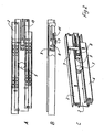
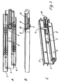
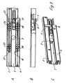
- Figuren 1A bis 9A
- Seitenansichten auf eine erfindungsgemäße Schubladenführungseinrichtung in unterschiedlichen Positionen;
- Figuren 1B bis 9B
- teilweise geschnittene Draufsichten auf die Schubladenführungseinrichtung nach den
Figuren 1A bis 9A , und - Figuren 1C bis 9C
- perspektivische Ansichten der Schubladenführungseinrichtung nach den
Figuren 1A bis 9A . - In den
Figuren 1A bis 1C ist eine Schubladenführungseinrichtung 1 gezeigt, so wie sie an einer Seite eines Schubkastens an einem feststehenden Möbelkorpus montiert wird. Dabei kann natürlich auf beiden Seiten der Schublade eine entsprechende Schubladenführungseinrichtung 1 vorgesehen sein, wobei die rechte und linke Seite der Schubladenführungseinrichtung 1 spiegelbildlich aufgebaut sind. Vorliegend ist jedoch nur die linke Seite der Schubladenführungseinrichtung 1 ohne einen mittig angeordneten Schubkasten dargestellt. - Die Schubladenführungseinrichtung 1 umfasst eine erste Schiene 2, die mit einem herausziehbaren Schubkasten verbunden ist. Die erste Schiene 2 ist über eine mittlere Führungsschiene 3 mit einer dritten Schiene 4 gekoppelt, die an einem Möbelkorpus festgelegt ist. Die Schienen 2 und 4 sowie die Führungsschiene 3 sind über Wälz- und Rollkörper 18, 20, 22, und 24 verschiebbar aneinander gehalten. Grundsätzlich ist die Erfindung jedoch auch für Schubladenführungseinrichtungen einsetzbar, bei denen drei oder mehr als drei Schienen 2, 3 und 4 vorgesehen sind.
- An der mittleren Führungsschiene 3 ist eine Rolle 5 gelagert, die sowohl an der Schiene 2 als auch an der Schiene 4 abrollt, sodass die mittlere Führungsschiene 3 mit der halben Geschwindigkeit wie die Schiene 2 relativ zu der stationären Schiene 4 bewegt wird.
- An der Schiene 4 ist eine Einzugsvorrichtung 6 vorgesehen, die mit einem stegförmig ausgebildeten Aktivator 7 zusammenwirkt, um über eine Teilstrecke vor der geschlossenen Position des Schubkastens diesen in den Möbelkorpus einzuziehen. Hierfür umfasst die Einzugsvorrichtung 6 einen Mitnehmer 8, der mit dem Aktivator 7 koppelbar ist, wobei der Aktivator 7 an der bewegbaren Schiene 2 festgelegt ist.
- Die Einzugsvorrichtung 6 umfasst an einem Gehäuse 14 eine Kurvenführung 11, die an einem Endabschnitt gebogen ist, sodass ein Mitnehmer 8 entlang der Kurvenführung 11 bewegt wird und an dem gebogenen Abschnitt 12 verschwenkt und geparkt wird. In der geparkten Position ist eine mit dem ruhenden Mitnehmer 8 verbundene Feder 13 gespannt, wobei die Feder 13 an dem vom Mitnehmer 8 abgewandten Ende an dem Gehäuse 14 festgelegt ist.
- Um die Laufbewegung der Schiene 3 relativ zu der am Möbelkorpus montierten Schiene 4 synchronisieren zu können, ist an der mittleren Führungsschiene 3 ein hervorstehender Anschlag 9 ausgebildet, der durch eine Öffnung 15 an dem Gehäuse 14 der Einzugsvorrichtung hindurchgeführt werden kann und beim Schließen in Wechselwirkung mit dem als stegförmiger Mitnehmer ausgebildeten Aktivator 7 treten kann. Die Funktion der Mittel zum Synchronisieren der Laufbewegung wird nachfolgend anhand der einzelnen Positionen erläutert:
- In
Figur 1A bis 1C ist die Schubladenführungseinrichtung 1 in einer geschlossenen Position gezeigt, in der Wälz- oder Rollkörper 18, 20, 22 und 24, die in einem Käfig gehalten sein können, an entsprechenden Anschlägen 17, 19, 21 und 23 an den Schienen 2 und 4 anliegen. Der Schubkasten wird dabei durch die Kraft der Feder 13 in der geschlossenen Position gehalten. - Wird der Schubkasten nun geöffnet, bewegt sich entsprechend den
Figuren 2A bis 2C die erste Schiene 2 nach links, wobei der stegförmige Aktivator 7 gegen die Kraft der Feder 13 den Mitnehmer 8 ebenfalls nach links bewegt. Der Mitnehmer 8 ist dabei in der Kurvenführung 11 geführt. Durch die Rolle 5 bewegt sich die mittlere Führungsschiene 3 gegenüber der Schiene 2 mit halber Geschwindigkeit, so dass der Anschlag 9 nur halb so schnell wie der Mitnehmer 8 bewegt wird. - In den
Figuren 3A bis 3C ist die Position der Schubladenführungseinrichtung 1 gezeigt, in der der Aktivator 7 die Aufnahme 16 an dem Mitnehmer 8 verlässt. Hierfür ist der Mitnehmer 8 in der Kurvenführung 11 an dem Abschnitt 12 verschwenkt worden, wobei durch das Verschwenken der Mitnehmer 8 in einer Parkposition fixiert ist, in der die Feder 13 gespannt bleibt. Sofern kein Schlupf zwischen den Schienen 2, 3 und 4 vorhanden ist, gelangt der Mitnehmer 8 in die Parkposition, wobei der Anschlag 9 durch den Mitnehmer 8 mit einem Gegenanschlag 10 allenfalls kontaktiert wird, es jedoch nicht zu einem Verschieben aufgrund der höheren Geschwindigkeit des Mitnehmers 8 gegenüber dem Anschlag 9 kommt. Der Anschlag 9 wird vielmehr durch eine Öffnung 15 in dem Gehäuse 14 der Einzugsvorrichtung 6 bewegt. Bei korrektem Lauf der Führungsschiene 3 verlässt der Anschlag 9 die Öffnung 15 in dem Gehäuse 14, während der Mitnehmer 8 mit dem Gegenanschlag 10 in der Parkposition verbleibt. - Wie in den
Figuren 4A bis 4C zu sehen ist, kann die Schiene 2 nun weiter in die geöffnete Position bewegt werden, wobei der Aktivator 7 eine Aufnahme 16 an dem Mitnehmer 8 verlässt und sich weiter nach links bewegt. Der Anschlag 9 bewegt sich weiter mit halber Geschwindigkeit gegenüber dem Aktivator 7. - In den
Figuren 5A bis 5C ist die geöffnete Position der Schubladenführungseinrichtung 1 gezeigt. Dabei können die Wälzkörper 22 an einem Endanschlag 25 anliegen, die den maximalen Auszugsweg begrenzen. - Wird nun der Schubkasten wieder in die geschlossene Position bewegt, so können die beim Öffnungsvorgang beschriebenen Positionen entsprechend den
Figuren 1 bis 4 wieder durchlaufen werden, sofern kein Schlupf zwischen den Schienen 2, 3 und 4 aufgetreten ist. Nachfolgend wird jedoch angenommen, dass aufgrund einer Bewegung des Schubkastens oder anderer Gründe eine gewisse Verschiebung der Schienen 2, 3 und 4 relativ zueinander stattgefunden hat und somit ein Schlupf vorhanden ist, insbesondere die Führungsschiene gegenüber dem korrektem Lauf weg zu weit im Möbelkorpus angeordnet ist. - Der Schubkasten wird dann in Richtung der geschlossenen Position bewegt, bis die in den
Figuren 6A bis 6C gezeigte Position erreicht ist. Anders als bei der Position in denFiguren 3A bis 3C , sind Anschlag 9 und Aktivator 7 gegenüber der ursprünglichen Anordnung versetzt zueinander positioniert, wobei der Anschlag 9 zuerst an den Mitnehmer 8 im Bereich des Gegenanschlages 10 anstößt, bevor der Aktivator 7 die Aufnahme 16 erreicht hat. Durch die kinetische Energie beim Schließen des Schubkastens kann jedoch die erforderliche Gleitreibung zum Verschieben der Schiene 2 relativ zu der Führungsschiene 3 und Schiene 4 problemlos überwunden werden, so dass die Rolle 5 überrutscht wird. Die mittlere Führungsschiene 3 wird dabei durch den Anschlag 9 eine kurve Zeit ortsfest gehalten, da der Anschlag 9 an dem Gegenanschlag 10 des Mitnehmers 8 anliegt und der Mitnehmer 8 aufgrund der gekippten Stellung in der Parkposition verbleibt. - Dadurch kann die in den
Figuren 7A bis 7C gezeigte Position erreicht werden, indem die Schiene 2 relativ zu der Führungsschiene 3 verschoben wird und somit der Aktivator 7 an dem Mitnehmer 8 anliegt und diesen aus der Parkposition wieder verschwenken kann. Der Aktivator 7 sorgt dabei für eine Schwenkbewegung des Mitnehmers 8, sodass dieser von der Parkposition herausbewegt wird. - In einem weiteren Schritt wird die Einzugsvorrichtung 6 aktiviert, wobei der Mitnehmer 8 wieder entlang der Kurvenführung 11 bewegt wird und durch die Feder 13 der Schubkasten in die geschlossene Position vorgespannt wird (
Figuren 8A bis 8C ). Da sich der Anschlag 9 nur mit halber Geschwindigkeit relativ zu dem Aktivator 7 und dem Mitnehmer 8 bewegt, entfernen sich die beiden Bauteile wieder voneinander. - In den
Figuren 9A bis 9C ist wieder die geschlossene Position der Schubladenführungseinrichtung 1 gezeigt, in der die Wälz- oder Rollkörper 18, 20, 22 und 24 an entsprechenden Anschlägen 17, 19, 21 und 23 an den Schienen 2 und 4 anliegen. Durch die Feder 13 der Einzugsvorrichtung 6 ist der Schubkasten in der geschlossenen Position gehalten. - In dem gezeigten Ausführungsbeispiel ist keine Dämpf oder Bremsvorrichtung gezeigt, die insbesondere im Bereich der Teilstrecke vorgesehen sein kann, in der auch die Einzugsvorrichtung 6 wirksam ist. Entsprechende Dämpfungseinrichtungen sind bekannt und können zusätzlich montiert werden oder mit der Einzugsvorrichtung 6 gekoppelt sein.
- Die Mittel zum zwangsweisen Synchronisieren der Laufbewegung können in beide Richtungen wirksam sein, wobei die Synchronisation auch in der Position stattfinden kann, die in den
Figuren 3A bis 3C dargestellt ist, wenn der Mitnehmer 8 mit dem Gegenanschlag 10 an dem Anschlag 9 zur Anlage kommt.
Claims (9)
- Schubladenführungseinrichtung (1) mit mindestens drei mittels Wälz- oder Rollkörpern (18, 20, 22, 24) zueinander verschiebbaren Schienen (2, 3, 4), wobei eine erste Schiene (2) mit einem ausziehbaren Möbelteil verbunden ist, eine zweite Schiene (3) eine mittlere Führungsschiene bildet, und eine dritte Schiene (4) mit einem Möbelkorpus verbunden ist und die erste, zweite und dritte Schiene (2, 3, 4) verschiebbar aneinander gehalten sind, wobei eine Einzugsvorrichtung (6) vorgesehen ist, mittels der die erste Schiene (2) in einer Teilstrecke der Einschubbewegung mittels Federkraft in eine Schließstellung bewegbar ist, wobei Mittel (9, 10) zum zwangsweisen Synchronisieren der Laufbewegung der relativ zueinander bewegbaren Schienen (2, 3, 4) vorgesehen sind, dadurch gekennzeichnet, dass die Mittel zum Synchronisieren einen Anschlag (9) umfassen, der vor dem Beginn der Teilstrecke der Einzugsvorrichtung (6) wirksam ist.
- Schubladenführungseinrichtung nach Anspruch 1, dadurch gekennzeichnet, dass an der mittleren Führungsschiene (3) eine Rolle (5) gelagert ist, die an der ersten und dritten Schiene (2, 4) anliegt
- Schubladenführungseinrichtung nach Anspruch 1 oder 2, dadurch gekennzeichnet, dass an der mittleren Führungsschiene (3) ein Anschlag (9) festgelegt ist, der zum Synchronisieren mit einem Gegenanschlag (10) zusammenwirkt.
- Schubladenführungseinrichtung nach Anspruch 3, dadurch gekennzeichnet, dass der Gegenanschlag (10) an einem Mitnehmer (8) der Einzugsvorrichtung (6) ausgebildet ist.
- Schubladenführungseinrichtung nach einem der Ansprüche 1 bis 4, dadurch gekennzeichnet, dass die Einzugsvorrichtung (6) an einem Mitnehmer (8) eine Aufnahme (16) aufweist, in die ein mit der ersten Schiene (2) gekoppelter Aktivator (7) eingreift.
- Schubladenführungseinrichtung nach einem der Ansprüche 1 bis 5, dadurch gekennzeichnet, dass die Einzugsvorrichtung (6) an der mit dem Möbelkorpus verbundenen Schiene (4) festgelegt ist.
- Schubladenführungseinrichtung nach einem der Ansprüche 1 bis 6, dadurch gekennzeichnet, dass eine Dämpf-bzw. Bremsvorrichtung entgegen der Einschubrichtung über eine Teilstrecke der Einschubrichtung wirksam wird, wobei die Dämpf bzw. Bremsvorrichtung einerseits mit der dritten Schiene (4) und andererseits mit der ersten Schiene (2) oder der zweiten Schiene (3) verbunden ist.
- Schubladenführungseinrichtung nach einem der Ansprüche 1 bis 7, dadurch gekennzeichnet, dass die Einzugsvorrichtung (6) ein Gehäuse (14) aufweist, das eine Öffnung (15) zur Durchführung des Anschlages (9) besitzt.
- Schrankmöbel mit einem Möbelkorpus und mindestens einem Schubkasten, dadurch gekennzeichnet, dass der Schubkasten an jeder Seite über eine Schubladenführungseinrichtung nach einem der vorhergehenden Ansprüche am Möbelkorpus gehalten ist.
Applications Claiming Priority (2)
| Application Number | Priority Date | Filing Date | Title |
|---|---|---|---|
| DE102004059802A DE102004059802A1 (de) | 2004-12-10 | 2004-12-10 | Schubkastenführungsschiene |
| PCT/EP2005/056243 WO2006061331A1 (de) | 2004-12-10 | 2005-11-25 | Schubladenführungseinrichtung |
Publications (2)
| Publication Number | Publication Date |
|---|---|
| EP1819256A1 EP1819256A1 (de) | 2007-08-22 |
| EP1819256B1 true EP1819256B1 (de) | 2015-08-12 |
Family
ID=35735255
Family Applications (1)
| Application Number | Title | Priority Date | Filing Date |
|---|---|---|---|
| EP05810975.2A Expired - Lifetime EP1819256B1 (de) | 2004-12-10 | 2005-11-25 | Schubladenführungseinrichtung |
Country Status (8)
| Country | Link |
|---|---|
| EP (1) | EP1819256B1 (de) |
| JP (1) | JP4620127B2 (de) |
| KR (1) | KR101284784B1 (de) |
| CN (1) | CN100544635C (de) |
| DE (1) | DE102004059802A1 (de) |
| ES (1) | ES2551702T3 (de) |
| RU (1) | RU2366351C2 (de) |
| WO (1) | WO2006061331A1 (de) |
Cited By (1)
| Publication number | Priority date | Publication date | Assignee | Title |
|---|---|---|---|---|
| US11459811B2 (en) | 2017-04-06 | 2022-10-04 | Karl Simon Gmbh & Co. Kg | Movement assembly |
Families Citing this family (23)
| Publication number | Priority date | Publication date | Assignee | Title |
|---|---|---|---|---|
| DE202005019147U1 (de) * | 2005-12-07 | 2007-04-19 | Alfit Ag | Ausziehführung für Schubladen u.dgl. aus dem Korpus eines Möbelstücks ausziehbarer Möbelteile |
| DE202006019009U1 (de) * | 2006-12-14 | 2008-04-24 | Paul Hettich Gmbh & Co. Kg | Teleskopführungsschiene für Möbelauszüge wie Schubkästen o.dgl. |
| US7748801B2 (en) | 2007-03-14 | 2010-07-06 | Alfit Ag | Telescopic guide for drawers and similar furniture components extendable from a body of furniture |
| DE202007012816U1 (de) * | 2007-09-13 | 2008-05-08 | Grass Gmbh | Vorrichtung mit einer Führungseinheit zur Führung eines relativ zu einem Korpus beweglichen Möbelauszugs |
| AT508265B1 (de) * | 2009-06-10 | 2013-05-15 | Blum Gmbh Julius | Ausziehführung für schubladen |
| AT509416B1 (de) * | 2010-02-03 | 2012-05-15 | Blum Gmbh Julius | Ausziehführung für eine schublade |
| CN102762128B (zh) * | 2010-02-04 | 2015-04-22 | Segos株式会社 | 滑动轨道固定装置 |
| DE102010016133A1 (de) * | 2010-03-25 | 2011-09-29 | Paul Hettich Gmbh & Co. Kg | Selbsteinzugsvorrichtung und Auszugsführung |
| JP5601571B2 (ja) * | 2010-05-25 | 2014-10-08 | 新東工業株式会社 | 鋳型造型装置におけるサンドタンクの砂供給口開閉装置 |
| DE102010017639A1 (de) * | 2010-06-29 | 2011-12-29 | Paul Hettich Gmbh & Co. Kg | Schrankmöbel mit einem Auszugsteil |
| DE102010036433A1 (de) * | 2010-07-15 | 2012-01-19 | Paul Hettich Gmbh & Co. Kg | Ausziehführung für Möbel und Verfahren zur Herstellung einer Auszugsführung |
| AT510361B1 (de) | 2010-08-23 | 2013-12-15 | Blum Gmbh Julius | Ausziehführung für schubladen |
| ITMI20111454A1 (it) * | 2011-07-29 | 2013-01-30 | Salice Arturo Spa | Dispositivo di aggancio per il fissaggio di un cassetto ad una guida |
| DE102011052524A1 (de) * | 2011-08-09 | 2013-02-14 | Schock Metallwerk Gmbh | Auszugführung |
| CN103535254B (zh) * | 2013-07-25 | 2017-02-08 | 魏延恕 | 具有控制区的抽出型无土栽培装置 |
| CN103535255B (zh) * | 2013-07-25 | 2016-12-28 | 魏延恕 | 模块化无土栽培装置 |
| CN103535256B (zh) * | 2013-07-25 | 2016-12-28 | 魏延恕 | 一种具有上开启盖的卧式柜抽出型无土栽培装置 |
| CN103535265A (zh) * | 2013-07-25 | 2014-01-29 | 魏延恕 | 一种顶管柜式无土栽培装置 |
| KR102361128B1 (ko) | 2015-07-02 | 2022-02-09 | 엘지전자 주식회사 | 건조기 |
| KR20180099249A (ko) * | 2017-02-28 | 2018-09-05 | (주)세고스 | 슬라이딩 장치 |
| RU203115U1 (ru) * | 2020-12-04 | 2021-03-22 | Общество с ограниченной ответственностью "БОЯРД" | Устройство автоматического выталкивания и фиксации подвижной части направляющей для выдвижного элемента мебели |
| IT202100024629A1 (it) * | 2021-09-27 | 2023-03-27 | Leonardo Spa | Sistema di movimentazione per spostare mezzi sensori di un aeromobile |
| CN114274883A (zh) * | 2021-12-24 | 2022-04-05 | 重庆长安汽车股份有限公司 | 一种汽车座椅储物盒结构、汽车座椅及汽车 |
Family Cites Families (11)
| Publication number | Priority date | Publication date | Assignee | Title |
|---|---|---|---|---|
| AT372830B (de) * | 1981-11-02 | 1983-11-25 | Fulterer Gmbh | Schubladenauszugeinrichtung in teleskopbauart |
| AT393948B (de) | 1989-04-03 | 1992-01-10 | Blum Gmbh Julius | Schliessvorrichtung fuer schubladen |
| ES2142364T3 (es) * | 1989-04-07 | 2000-04-16 | Asahi Glass Co Ltd | Filtro ceramico para gas conteniendo polvo y metodo para su produccion. |
| EP1161164B1 (de) | 2000-01-14 | 2003-12-10 | Julius Blum Gesellschaft m.b.H. | Ausziehführungsgarnitur für schubladen |
| AT409067B (de) * | 2000-03-02 | 2002-05-27 | Blum Gmbh Julius | Ausziehführung für schubladen |
| DE10228470A1 (de) * | 2002-06-26 | 2004-01-15 | Grass Gmbh | Schubladenführung |
| DE20307757U1 (de) * | 2002-07-22 | 2003-07-10 | Julius Blum Gesellschaft M.B.H., Innsbruck | Ausziehführungsgarnitur für Schubladen |
| AT6364U1 (de) * | 2002-08-29 | 2003-09-25 | Blum Gmbh Julius | Ausziehführungsgarnitur für schubladen |
| US7028370B2 (en) * | 2003-03-31 | 2006-04-18 | Thk Co., Ltd. | Retracting apparatus, drawer apparatus and sliding door apparatus |
| KR200349789Y1 (ko) * | 2004-02-12 | 2004-05-12 | 남동희 | 가구용 슬라이드 다단레일 |
| KR200390556Y1 (ko) | 2005-04-22 | 2005-07-22 | 장진영 | 슬라이딩 레일 |
-
2004
- 2004-12-10 DE DE102004059802A patent/DE102004059802A1/de not_active Ceased
-
2005
- 2005-11-25 JP JP2007544878A patent/JP4620127B2/ja not_active Expired - Fee Related
- 2005-11-25 KR KR1020077015045A patent/KR101284784B1/ko not_active Expired - Fee Related
- 2005-11-25 RU RU2007124077/12A patent/RU2366351C2/ru not_active IP Right Cessation
- 2005-11-25 WO PCT/EP2005/056243 patent/WO2006061331A1/de not_active Ceased
- 2005-11-25 ES ES05810975.2T patent/ES2551702T3/es not_active Expired - Lifetime
- 2005-11-25 CN CNB2005800422341A patent/CN100544635C/zh not_active Expired - Fee Related
- 2005-11-25 EP EP05810975.2A patent/EP1819256B1/de not_active Expired - Lifetime
Cited By (1)
| Publication number | Priority date | Publication date | Assignee | Title |
|---|---|---|---|---|
| US11459811B2 (en) | 2017-04-06 | 2022-10-04 | Karl Simon Gmbh & Co. Kg | Movement assembly |
Also Published As
| Publication number | Publication date |
|---|---|
| KR101284784B1 (ko) | 2013-07-10 |
| EP1819256A1 (de) | 2007-08-22 |
| RU2366351C2 (ru) | 2009-09-10 |
| CN100544635C (zh) | 2009-09-30 |
| RU2007124077A (ru) | 2009-01-20 |
| CN101072525A (zh) | 2007-11-14 |
| DE102004059802A1 (de) | 2006-06-14 |
| JP4620127B2 (ja) | 2011-01-26 |
| JP2008522690A (ja) | 2008-07-03 |
| KR20070089728A (ko) | 2007-08-31 |
| WO2006061331A1 (de) | 2006-06-15 |
| ES2551702T3 (es) | 2015-11-23 |
Similar Documents
| Publication | Publication Date | Title |
|---|---|---|
| WO2006061331A1 (de) | Schubladenführungseinrichtung | |
| EP2770876B1 (de) | Synchronisierte verriegelung für ein bewegbares möbelteil | |
| EP3622155B1 (de) | Führungssystem zur führung eines türflügels | |
| EP2144531B1 (de) | Ausziehführung für schubladen | |
| EP2538818B1 (de) | Ausziehführung für schubladen | |
| EP2992781B1 (de) | Ausziehführung | |
| EP2373195B1 (de) | Selbsteinzugsvorrichtung und auszugsführung | |
| EP3668351B1 (de) | Schubladenausziehführung | |
| EP2019607B1 (de) | SCHLIEß- UND HALTEVORRICHTUNG FÜR EINE AUSZIEHFÜHRUNG | |
| EP3668350B1 (de) | Schubladenausziehführung | |
| AT506062B1 (de) | Rollen-ausziehführung | |
| EP3518707B1 (de) | Einzugsvorrichtung für einen schubladenauszug | |
| EP3531869B1 (de) | Antriebsvorrichtung für ein bewegbares möbelteil | |
| AT507186B1 (de) | Rollenausziehführung | |
| EP2046164B1 (de) | Ausziehführung zur führung von möbelteilen | |
| AT520805A1 (de) | Ausziehführung | |
| WO2024231439A1 (de) | Differenzialausziehführung | |
| AT500157A2 (de) | Schubladenführung |
Legal Events
| Date | Code | Title | Description |
|---|---|---|---|
| PUAI | Public reference made under article 153(3) epc to a published international application that has entered the european phase |
Free format text: ORIGINAL CODE: 0009012 |
|
| 17P | Request for examination filed |
Effective date: 20070523 |
|
| AK | Designated contracting states |
Kind code of ref document: A1 Designated state(s): AT BE BG CH CY CZ DE DK EE ES FI FR GB GR HU IE IS IT LI LT LU LV MC NL PL PT RO SE SI SK TR |
|
| DAX | Request for extension of the european patent (deleted) | ||
| 17Q | First examination report despatched |
Effective date: 20080527 |
|
| GRAP | Despatch of communication of intention to grant a patent |
Free format text: ORIGINAL CODE: EPIDOSNIGR1 |
|
| INTG | Intention to grant announced |
Effective date: 20150210 |
|
| GRAS | Grant fee paid |
Free format text: ORIGINAL CODE: EPIDOSNIGR3 |
|
| GRAP | Despatch of communication of intention to grant a patent |
Free format text: ORIGINAL CODE: EPIDOSNIGR1 |
|
| GRAA | (expected) grant |
Free format text: ORIGINAL CODE: 0009210 |
|
| INTG | Intention to grant announced |
Effective date: 20150630 |
|
| AK | Designated contracting states |
Kind code of ref document: B1 Designated state(s): AT BE BG CH CY CZ DE DK EE ES FI FR GB GR HU IE IS IT LI LT LU LV MC NL PL PT RO SE SI SK TR |
|
| REG | Reference to a national code |
Ref country code: GB Ref legal event code: FG4D Free format text: NOT ENGLISH |
|
| REG | Reference to a national code |
Ref country code: CH Ref legal event code: EP |
|
| REG | Reference to a national code |
Ref country code: AT Ref legal event code: REF Ref document number: 741344 Country of ref document: AT Kind code of ref document: T Effective date: 20150815 |
|
| REG | Reference to a national code |
Ref country code: IE Ref legal event code: FG4D Free format text: LANGUAGE OF EP DOCUMENT: GERMAN |
|
| REG | Reference to a national code |
Ref country code: DE Ref legal event code: R096 Ref document number: 502005014892 Country of ref document: DE |
|
| REG | Reference to a national code |
Ref country code: ES Ref legal event code: FG2A Ref document number: 2551702 Country of ref document: ES Kind code of ref document: T3 Effective date: 20151123 |
|
| REG | Reference to a national code |
Ref country code: LT Ref legal event code: MG4D |
|
| REG | Reference to a national code |
Ref country code: NL Ref legal event code: MP Effective date: 20150812 |
|
| PG25 | Lapsed in a contracting state [announced via postgrant information from national office to epo] |
Ref country code: GR Free format text: LAPSE BECAUSE OF FAILURE TO SUBMIT A TRANSLATION OF THE DESCRIPTION OR TO PAY THE FEE WITHIN THE PRESCRIBED TIME-LIMIT Effective date: 20151113 Ref country code: LT Free format text: LAPSE BECAUSE OF FAILURE TO SUBMIT A TRANSLATION OF THE DESCRIPTION OR TO PAY THE FEE WITHIN THE PRESCRIBED TIME-LIMIT Effective date: 20150812 Ref country code: LV Free format text: LAPSE BECAUSE OF FAILURE TO SUBMIT A TRANSLATION OF THE DESCRIPTION OR TO PAY THE FEE WITHIN THE PRESCRIBED TIME-LIMIT Effective date: 20150812 Ref country code: FI Free format text: LAPSE BECAUSE OF FAILURE TO SUBMIT A TRANSLATION OF THE DESCRIPTION OR TO PAY THE FEE WITHIN THE PRESCRIBED TIME-LIMIT Effective date: 20150812 |
|
| PG25 | Lapsed in a contracting state [announced via postgrant information from national office to epo] |
Ref country code: IS Free format text: LAPSE BECAUSE OF FAILURE TO SUBMIT A TRANSLATION OF THE DESCRIPTION OR TO PAY THE FEE WITHIN THE PRESCRIBED TIME-LIMIT Effective date: 20151212 Ref country code: PT Free format text: LAPSE BECAUSE OF FAILURE TO SUBMIT A TRANSLATION OF THE DESCRIPTION OR TO PAY THE FEE WITHIN THE PRESCRIBED TIME-LIMIT Effective date: 20151214 Ref country code: SE Free format text: LAPSE BECAUSE OF FAILURE TO SUBMIT A TRANSLATION OF THE DESCRIPTION OR TO PAY THE FEE WITHIN THE PRESCRIBED TIME-LIMIT Effective date: 20150812 Ref country code: PL Free format text: LAPSE BECAUSE OF FAILURE TO SUBMIT A TRANSLATION OF THE DESCRIPTION OR TO PAY THE FEE WITHIN THE PRESCRIBED TIME-LIMIT Effective date: 20150812 |
|
| PG25 | Lapsed in a contracting state [announced via postgrant information from national office to epo] |
Ref country code: NL Free format text: LAPSE BECAUSE OF FAILURE TO SUBMIT A TRANSLATION OF THE DESCRIPTION OR TO PAY THE FEE WITHIN THE PRESCRIBED TIME-LIMIT Effective date: 20150812 |
|
| PG25 | Lapsed in a contracting state [announced via postgrant information from national office to epo] |
Ref country code: SK Free format text: LAPSE BECAUSE OF FAILURE TO SUBMIT A TRANSLATION OF THE DESCRIPTION OR TO PAY THE FEE WITHIN THE PRESCRIBED TIME-LIMIT Effective date: 20150812 Ref country code: DK Free format text: LAPSE BECAUSE OF FAILURE TO SUBMIT A TRANSLATION OF THE DESCRIPTION OR TO PAY THE FEE WITHIN THE PRESCRIBED TIME-LIMIT Effective date: 20150812 Ref country code: CZ Free format text: LAPSE BECAUSE OF FAILURE TO SUBMIT A TRANSLATION OF THE DESCRIPTION OR TO PAY THE FEE WITHIN THE PRESCRIBED TIME-LIMIT Effective date: 20150812 Ref country code: EE Free format text: LAPSE BECAUSE OF FAILURE TO SUBMIT A TRANSLATION OF THE DESCRIPTION OR TO PAY THE FEE WITHIN THE PRESCRIBED TIME-LIMIT Effective date: 20150812 |
|
| REG | Reference to a national code |
Ref country code: DE Ref legal event code: R097 Ref document number: 502005014892 Country of ref document: DE |
|
| PG25 | Lapsed in a contracting state [announced via postgrant information from national office to epo] |
Ref country code: RO Free format text: LAPSE BECAUSE OF FAILURE TO SUBMIT A TRANSLATION OF THE DESCRIPTION OR TO PAY THE FEE WITHIN THE PRESCRIBED TIME-LIMIT Effective date: 20150812 |
|
| PLBE | No opposition filed within time limit |
Free format text: ORIGINAL CODE: 0009261 |
|
| STAA | Information on the status of an ep patent application or granted ep patent |
Free format text: STATUS: NO OPPOSITION FILED WITHIN TIME LIMIT |
|
| PG25 | Lapsed in a contracting state [announced via postgrant information from national office to epo] |
Ref country code: MC Free format text: LAPSE BECAUSE OF FAILURE TO SUBMIT A TRANSLATION OF THE DESCRIPTION OR TO PAY THE FEE WITHIN THE PRESCRIBED TIME-LIMIT Effective date: 20150812 Ref country code: LU Free format text: LAPSE BECAUSE OF FAILURE TO SUBMIT A TRANSLATION OF THE DESCRIPTION OR TO PAY THE FEE WITHIN THE PRESCRIBED TIME-LIMIT Effective date: 20151125 |
|
| REG | Reference to a national code |
Ref country code: CH Ref legal event code: PL |
|
| 26N | No opposition filed |
Effective date: 20160513 |
|
| GBPC | Gb: european patent ceased through non-payment of renewal fee |
Effective date: 20151125 |
|
| PG25 | Lapsed in a contracting state [announced via postgrant information from national office to epo] |
Ref country code: LI Free format text: LAPSE BECAUSE OF NON-PAYMENT OF DUE FEES Effective date: 20151130 Ref country code: CH Free format text: LAPSE BECAUSE OF NON-PAYMENT OF DUE FEES Effective date: 20151130 |
|
| REG | Reference to a national code |
Ref country code: IE Ref legal event code: MM4A |
|
| REG | Reference to a national code |
Ref country code: FR Ref legal event code: ST Effective date: 20160729 |
|
| PG25 | Lapsed in a contracting state [announced via postgrant information from national office to epo] |
Ref country code: SI Free format text: LAPSE BECAUSE OF FAILURE TO SUBMIT A TRANSLATION OF THE DESCRIPTION OR TO PAY THE FEE WITHIN THE PRESCRIBED TIME-LIMIT Effective date: 20150812 |
|
| PG25 | Lapsed in a contracting state [announced via postgrant information from national office to epo] |
Ref country code: GB Free format text: LAPSE BECAUSE OF NON-PAYMENT OF DUE FEES Effective date: 20151125 Ref country code: IE Free format text: LAPSE BECAUSE OF NON-PAYMENT OF DUE FEES Effective date: 20151125 |
|
| REG | Reference to a national code |
Ref country code: DE Ref legal event code: R079 Ref document number: 502005014892 Country of ref document: DE Free format text: PREVIOUS MAIN CLASS: A47B0088040000 Ipc: A47B0088400000 |
|
| PG25 | Lapsed in a contracting state [announced via postgrant information from national office to epo] |
Ref country code: FR Free format text: LAPSE BECAUSE OF NON-PAYMENT OF DUE FEES Effective date: 20151130 |
|
| PGFP | Annual fee paid to national office [announced via postgrant information from national office to epo] |
Ref country code: ES Payment date: 20161124 Year of fee payment: 12 |
|
| PGFP | Annual fee paid to national office [announced via postgrant information from national office to epo] |
Ref country code: TR Payment date: 20161120 Year of fee payment: 12 |
|
| PG25 | Lapsed in a contracting state [announced via postgrant information from national office to epo] |
Ref country code: BG Free format text: LAPSE BECAUSE OF FAILURE TO SUBMIT A TRANSLATION OF THE DESCRIPTION OR TO PAY THE FEE WITHIN THE PRESCRIBED TIME-LIMIT Effective date: 20150812 Ref country code: HU Free format text: LAPSE BECAUSE OF FAILURE TO SUBMIT A TRANSLATION OF THE DESCRIPTION OR TO PAY THE FEE WITHIN THE PRESCRIBED TIME-LIMIT; INVALID AB INITIO Effective date: 20051125 |
|
| PG25 | Lapsed in a contracting state [announced via postgrant information from national office to epo] |
Ref country code: CY Free format text: LAPSE BECAUSE OF FAILURE TO SUBMIT A TRANSLATION OF THE DESCRIPTION OR TO PAY THE FEE WITHIN THE PRESCRIBED TIME-LIMIT Effective date: 20150812 |
|
| PG25 | Lapsed in a contracting state [announced via postgrant information from national office to epo] |
Ref country code: BE Free format text: LAPSE BECAUSE OF NON-PAYMENT OF DUE FEES Effective date: 20151130 |
|
| PGFP | Annual fee paid to national office [announced via postgrant information from national office to epo] |
Ref country code: IT Payment date: 20171122 Year of fee payment: 13 |
|
| REG | Reference to a national code |
Ref country code: ES Ref legal event code: FD2A Effective date: 20190103 |
|
| PG25 | Lapsed in a contracting state [announced via postgrant information from national office to epo] |
Ref country code: ES Free format text: LAPSE BECAUSE OF NON-PAYMENT OF DUE FEES Effective date: 20171126 |
|
| PG25 | Lapsed in a contracting state [announced via postgrant information from national office to epo] |
Ref country code: IT Free format text: LAPSE BECAUSE OF NON-PAYMENT OF DUE FEES Effective date: 20181125 |
|
| PGFP | Annual fee paid to national office [announced via postgrant information from national office to epo] |
Ref country code: AT Payment date: 20201117 Year of fee payment: 16 |
|
| PG25 | Lapsed in a contracting state [announced via postgrant information from national office to epo] |
Ref country code: TR Free format text: LAPSE BECAUSE OF NON-PAYMENT OF DUE FEES Effective date: 20171125 |
|
| REG | Reference to a national code |
Ref country code: AT Ref legal event code: MM01 Ref document number: 741344 Country of ref document: AT Kind code of ref document: T Effective date: 20211125 |
|
| PG25 | Lapsed in a contracting state [announced via postgrant information from national office to epo] |
Ref country code: AT Free format text: LAPSE BECAUSE OF NON-PAYMENT OF DUE FEES Effective date: 20211125 |
|
| P01 | Opt-out of the competence of the unified patent court (upc) registered |
Effective date: 20230407 |
|
| PGFP | Annual fee paid to national office [announced via postgrant information from national office to epo] |
Ref country code: DE Payment date: 20231120 Year of fee payment: 19 |
|
| REG | Reference to a national code |
Ref country code: DE Ref legal event code: R119 Ref document number: 502005014892 Country of ref document: DE |
|
| PG25 | Lapsed in a contracting state [announced via postgrant information from national office to epo] |
Ref country code: DE Free format text: LAPSE BECAUSE OF NON-PAYMENT OF DUE FEES Effective date: 20250603 |