EP1818708A2 - Zoomobjektiv und Bildaufnahmevorrichtung - Google Patents
Zoomobjektiv und Bildaufnahmevorrichtung Download PDFInfo
- Publication number
- EP1818708A2 EP1818708A2 EP07102029A EP07102029A EP1818708A2 EP 1818708 A2 EP1818708 A2 EP 1818708A2 EP 07102029 A EP07102029 A EP 07102029A EP 07102029 A EP07102029 A EP 07102029A EP 1818708 A2 EP1818708 A2 EP 1818708A2
- Authority
- EP
- European Patent Office
- Prior art keywords
- lens
- lens unit
- image
- positive
- subunit
- Prior art date
- Legal status (The legal status is an assumption and is not a legal conclusion. Google has not performed a legal analysis and makes no representation as to the accuracy of the status listed.)
- Withdrawn
Links
Images


Classifications
-
- G—PHYSICS
- G02—OPTICS
- G02B—OPTICAL ELEMENTS, SYSTEMS OR APPARATUS
- G02B15/00—Optical objectives with means for varying the magnification
- G02B15/14—Optical objectives with means for varying the magnification by axial movement of one or more lenses or groups of lenses relative to the image plane for continuously varying the equivalent focal length of the objective
- G02B15/145—Optical objectives with means for varying the magnification by axial movement of one or more lenses or groups of lenses relative to the image plane for continuously varying the equivalent focal length of the objective having five groups only
- G02B15/1451—Optical objectives with means for varying the magnification by axial movement of one or more lenses or groups of lenses relative to the image plane for continuously varying the equivalent focal length of the objective having five groups only the first group being positive
- G02B15/145129—Optical objectives with means for varying the magnification by axial movement of one or more lenses or groups of lenses relative to the image plane for continuously varying the equivalent focal length of the objective having five groups only the first group being positive arranged +-+++
-
- G—PHYSICS
- G02—OPTICS
- G02B—OPTICAL ELEMENTS, SYSTEMS OR APPARATUS
- G02B13/00—Optical objectives specially designed for the purposes specified below
- G02B13/001—Miniaturised objectives for electronic devices, e.g. portable telephones, webcams, PDAs, small digital cameras
- G02B13/009—Miniaturised objectives for electronic devices, e.g. portable telephones, webcams, PDAs, small digital cameras having zoom function
-
- G—PHYSICS
- G02—OPTICS
- G02B—OPTICAL ELEMENTS, SYSTEMS OR APPARATUS
- G02B27/00—Optical systems or apparatus not provided for by any of the groups G02B1/00 - G02B26/00, G02B30/00
- G02B27/64—Imaging systems using optical elements for stabilisation of the lateral and angular position of the image
- G02B27/646—Imaging systems using optical elements for stabilisation of the lateral and angular position of the image compensating for small deviations, e.g. due to vibration or shake
-
- G—PHYSICS
- G02—OPTICS
- G02B—OPTICAL ELEMENTS, SYSTEMS OR APPARATUS
- G02B3/00—Simple or compound lenses
- G02B3/0087—Simple or compound lenses with index gradient
-
- G—PHYSICS
- G03—PHOTOGRAPHY; CINEMATOGRAPHY; ANALOGOUS TECHNIQUES USING WAVES OTHER THAN OPTICAL WAVES; ELECTROGRAPHY; HOLOGRAPHY
- G03B—APPARATUS OR ARRANGEMENTS FOR TAKING PHOTOGRAPHS OR FOR PROJECTING OR VIEWING THEM; APPARATUS OR ARRANGEMENTS EMPLOYING ANALOGOUS TECHNIQUES USING WAVES OTHER THAN OPTICAL WAVES; ACCESSORIES THEREFOR
- G03B17/00—Details of cameras or camera bodies; Accessories therefor
- G03B17/02—Bodies
- G03B17/12—Bodies with means for supporting objectives, supplementary lenses, filters, masks, or turrets
-
- H—ELECTRICITY
- H04—ELECTRIC COMMUNICATION TECHNIQUE
- H04N—PICTORIAL COMMUNICATION, e.g. TELEVISION
- H04N23/00—Cameras or camera modules comprising electronic image sensors; Control thereof
- H04N23/50—Constructional details
- H04N23/55—Optical parts specially adapted for electronic image sensors; Mounting thereof
Definitions
- the present invention relates to a non-obvious zoom lens system and an image-pickup apparatus. More specifically, it relates to a zoom lens system capable of shifting an image by shifting part of a lens in a direction substantially orthogonal to the optical axis and relates to an image-pickup apparatus including the zoom lens system.
- CMOS complementary method-oxide semiconductor
- an optical shake-correction system As a shake-correction method of correcting the shaking of an image caused by the shaking of the optical system, an optical shake-correction system is known.
- a lens-shift method in which part of a lens system is shifted in a direction orthogonal to the optical axis or a variable apex-angle prism method in which the apex angle of a prism disposed immediately before a lens system is changed are known.
- the variable apex-angle prism method there is a problem that the size of the system including a driving system is large since the variable apex-angle prism is disposed on the object side of a first lens unit, which is the largest in the lens system.
- the optical system of the lens system method can function as an optical shake-correction system for correcting shaking of an image caused by shaking of a camera by shifting lenses using a driving system by, for example, combining a detecting system for detecting shaking of the camera caused by shaking due to, for example, shutter release, a control system for obtaining, on the basis of a signal output from the detecting system, a correction value that is to be applied to the lens position, and a shift-driving system for driving the shifting of a lens on the basis of the output from the control system.
- a driving system by, for example, combining a detecting system for detecting shaking of the camera caused by shaking due to, for example, shutter release, a control system for obtaining, on the basis of a signal output from the detecting system, a correction value that is to be applied to the lens position, and a shift-driving system for driving the shifting of a lens on the basis of the output from the control system.
- the zoom lens system described in Japanese Unexamined Patent Application Publication No. 2005-215385 includes, in order from the object side, a first lens unit having positive refractive power, a second lens unit having negative refractive power, a third lens unit having positive refractive power, and a fourth lens unit having positive refractive power.
- the zoom lens system is configured in a manner such that, when the lens positions change from the wide-angle end to the telephoto end, the first lens unit moves toward the object, the second lens unit moves toward the image, the third lens unit once moves toward the object and then moves toward the image, and the fourth lens unit once moves toward the object and then moves toward the image.
- an image is shifted by shifting the entire third lens unit in a direction substantially orthogonal to the optical axis.
- the zoom lens system described in Japanese Unexamined Patent Application Publication No. 2005-128186 includes, in order from the object side, a first lens unit having positive refractive power, a second lens unit having negative refractive power, a third lens unit having positive refractive power, and a fourth lens unit having positive refractive power.
- the zoom lens system is configured in a manner such that, when the lens positions change from the wide-angle end to the telephoto end, the first lens unit and the third lens unit are fixed in the optical axis direction, the second lens unit moves toward the image, and the fourth lens unit moves so as to compensate for the displacement in the image plane position caused by the movement of the second lens unit.
- an image is shifted by shifting the entire third lens unit in a direction substantially orthogonal to the optical axis.
- the zoom lens system described in Japanese Unexamined Patent Application Publication No. 2004-252196 includes, in order from the object side, a first lens unit having positive refractive power, a second lens unit having negative refractive power, a third lens unit having positive refractive power, a fourth lens unit having positive refractive power, and a fifth lens unit having positive refractive power.
- the zoom lens system is configured in a manner such that, when the lens positions change from the wide-angle end to the telephoto end, the first to fourth lens units move so that the distance between the first lens unit and the second lens unit increases, the distance between the second lens unit and the third lens unit decreases, the distance between the third lens unit and the fourth lens unit increases, and the fifth lens unit is fixed in the optical axis direction.
- the third lens unit includes two subunits. With the zoom lens system, an image is shifted by shifting one of the subunits in a direction substantially orthogonal to the optical axis.
- the zoom lens system according to Japanese Unexamined Patent Application Publication No. 2005-128186 shifts the image by shifting the third lens unit.
- the diameter of the lenses cannot be sufficiently reduced.
- the third lens unit has a great positive refractive power, it includes two subunits, i.e., a positive subunit and a negative subunit, for correcting distortion.
- the diffusion effect by the negative subunit must be weakened.
- the diffusion effect of the second lens unit must be weakened, causing an increase in the lens diameter.
- the aperture stop and the third lens unit are moved separately so as to reduce the diameter of the lenses.
- the number of driving mechanisms must be increased, causing the structure of the barrel to be complex and increasing the barrel diameter.
- part of the third lens unit is shifted to shift the image.
- the driving mechanism for the aperture stop and the driving mechanism for shifting the lenses are disposed close to each other in the optical axis direction, the barrel diameter is great and the clearance in the optical axis direction is great. Therefore, the size of the zoom lens system cannot be sufficiently reduced.
- a zoom lens according to an embodiment of the present invention has a high magnification, is suitable for decreasing the lens diameter, and is capable of shifting an image.
- a zoom lens system includes, in order from an object side, a first lens unit having positive refractive power, a second lens unit having negative refractive power, a third lens unit having positive refractive power, a fourth lens unit having positive refractive power, and a fifth lens unit.
- the first to fourth lens units are movable in an optical axis direction
- the second lens unit moves toward an image
- the third lens unit moves toward the object so that the distance between the first lens unit and the second lens unit increases and the distance between the second lens unit and the third lens unit decreases
- the fourth lens moves in the optical axis direction to compensate for a displacement of an image plane due to the movement of the lens units.
- the fifth lens unit includes a negative subunit having negative refractive power and a positive subunit having positive refractive power and being disposed on the image side of the negative subunit with a predetermined air gap the negative subunit and the positive subunit, and is capable of shifting the image by shifting the positive subunit in a direction substantially orthogonal to the optical axis.
- An aperture is provided closer to the object than the fifth lens unit. The following Expression 1 is satisfied: 0.03 ⁇ ⁇ S / ft ⁇ 0.15 where ⁇ S represents the movement from the aperture stop at the wide-angle end to the aperture stop at the telephoto end (in which the movement toward the object is positive), and ft represents the focal length at the telephoto end.
- An image-pickup apparatus includes a zoom lens system according to an embodiment of the present invention.
- the zooms lens system according to an embodiment of the present invention has high magnification, is suitable for reducing the diameter of lenses, and is capable of shifting an image.
- a zoom lens system according to an embodiment of the present invention may employ configurations 1 to 6 as described below.
- An image-pickup apparatus may employ configurations 1 to 3 as described below.
- a zoom lens system includes, in order from the object side, a first lens unit having positive refractive power, a second lens unit having negative refractive power, a third lens unit having positive refractive power, a fourth lens unit having positive refractive power, and a fifth lens unit.
- the second lens unit moves toward the image and the third lens unit moves toward the object so that the distance between the first lens unit and the second lens unit increases and the distance between the second lens unit and the third lens unit decreases, and the fourth lens unit moves in the optical axis direction so as to compensate for the displacement of the image plane caused by the movement of the lens units.
- the fifth lens unit includes a negative subunit having negative refractive power and a positive subunit having positive refractive power and being disposed on the image side of the negative lens unit with an air gap provided therebetween.
- an aperture stop is provided closer to the object than the fifth lens unit is, and the following Expression 1 is satisfied: 0.03 ⁇ ⁇ S / ft ⁇ 0.15 where ⁇ S represents the movement from the aperture stop at the wide-angle end to the aperture stop at the telephoto end (in which the movement toward the object is positive), and ft represents the focal length at the telephoto end.
- a known zoom lens system has a problem in that functions for correcting aberration are concentrated on the third lens unit.
- the fifth lens unit is disposed on the image side of the fourth lens unit so as to simplify the lens configuration of the third lens unit. In this way, high magnification and high performance are both achieved.
- the zoom lens system according to an embodiment of the present invention reduces the burden placed on the third lens unit for aberration correction by disposing the fifth lens unit on the image side of the fourth lens unit.
- the fifth lens unit includes a negative subunit having negative refractive power and a positive subunit having positive refractive power and being disposed on the image side of the negative subunit. In this way, the burden placed on the third lens unit for aberration correction is reduced, and both high magnification and stable optical quality obtained at production are achieved.
- the fifth lens unit of a zoom lens system according to an embodiment of the present invention has two functions.
- the first function is a function for adjusting the exit pupil position.
- the second function is a function for correcting distortion.
- the flexibility of the exit pupil position in a lens system that is disposed on the object side of the fifth lens unit increases, and, in particular, the flexibility in the design of the angle of the principal light beam that is emitted from the third lens unit to the optical axis increases.
- the third lens unit can be configured of only positive subunits. Accordingly, the structure of the third lens unit can be simplified.
- the third lens unit does not have to be shifted in a direction orthogonal to the optical axis, the refractive power of the second lens unit can be increased, and the off-axis light beam passing through the first lens unit moves closer to the optical axis. In this way, the lens diameter can be reduced.
- the fluctuation in the distortion that is generated when shifting an image can be satisfactorily corrected by applying the fact that the exit pupil position can be adjusted by configuring the fifth lens unit of the zoom lens system according to an embodiment of the present invention with a negative subunit and a positive subunit, as described above.
- Fig. 24 illustrates an optical path when the exit pupil is positioned at infinity and when the camera is not shaken.
- G5p represents the positive subunit of the fifth lens unit
- x represents the optical axis
- S represents the aperture stop
- IMG represents the image plane.
- the camera is actually slightly shaken, but in Figs. 24 to 27, the shaking is enhanced to a greater magnitude than the actual shaking so that it is visible.
- Fig. 25 illustrates the optical path in Fig. 24 when shaking of the camera causes the incident angle to the optical system to be displaced.
- Fig. 26 illustrates the optical path when the positive subunit G5p, in the state shown in Fig.
- Fig. 27 illustrates the principal light beam (solid line) when the camera is not shaken and the principal light beam (dotted line) when the shaking of the camera is corrected.
- the positive subunit is configured of one positive lens and one negative lens, and the spherical aberration and the sine condition are corrected simultaneously. In this way, distortion generated during shifting can be satisfactorily corrected.
- the position of the aperture stop is extremely important when determining the exit pupil position.
- the zoom lens system As described above, with the zoom lens system according to an embodiment of the present invention, it is desirable to approximate the exit pupil position to infinity regardless of the lens positions so as to satisfactorily correct the fluctuation in distortion generated when the positive subunit is shifted. To suppress the displacement in the exit pupil position, it is effective to reduce the moving of the aperture stop in the optical axis direction when the lens positions change.
- the aperture stop By moving the aperture stop, the height of the off-axis light beam that passes through each lens unit can be actively changed, and high magnitude and high performance can be achieved.
- the zoom lens system according to an embodiment of the present invention is capable to shift an image, and both high magnitude and high performance are achieved.
- Expression 1 is presented again below: 0.03 ⁇ ⁇ S / ft ⁇ 0.15 where ⁇ S represents the movement from the aperture stop at the wide-angle end to the aperture stop at the telephoto end (in which the movement toward the object is positive), and ft represents the focal length at the telephoto end.
- Expression 1 defines the amount of movement of the aperture stop when the lens positions change from the wide-angle end to the telephoto end.
- Expression 2 defines the bending shape of the positive subunit disposed in the fifth lens unit.
- the zoom lens system it is desirable to dispose the aperture stop in the vicinity of the third lens unit so as to maintain the balance between a small lens diameter and high performance.
- the off-axis light beam passing through the third lens unit moves closer to the optical axis by disposing the aperture stop in the vicinity of the third lens unit. Therefore, the aberration correction function of the third lens unit can be used mainly for correcting the axial chromatic aberration, and high performance can be achieved.
- the zoom lens system when the lens positions change from the wide-angle end to the telephoto end, the off-axis light beam passing through the second lens unit moves closer to the optical axis and the off-axis light beam passing through the first lens unit and the fourth lens unit changes by disposing the aperture stop in the vicinity of the third lens unit.
- both a reduced lens diameter and high performance can be achieved by satisfying the following Expression 3: 0.3 ⁇ D SW / T ⁇ L W ⁇ 0.4 where D sw represents the distance from the aperture stop to the image plane at the telephoto end, and TL w represents the entire length of the lens system at the telephoto end.
- Expression 3 defines the aperture stop position at the wide-angle end.
- the structure of the lens barrel can be simplified.
- the zoom lens system to reduce the number of movable lens units and simplify the structure of the lens barrel, it is desirable to fix the fifth lens unit in the optical axis direction, regardless of the lens positions.
- Expression 4 defines the focal length of the fifth lens unit.
- the exit pupil position is a positive (+) value since the light beam is intensely diffused by the negative subunit disposed in the fifth lens unit. More specifically, as shown in Fig. 23, since a principal light beam L that is transmitted through the fifth lens unit G5 and reaches the image plane IMG moves close to the optical axis x, the off-axis light beam that is transmitted through the fifth lens unit G5 moves away from the optical axis. Thus, it becomes difficult to satisfactorily correct the coma aberration generated on the screen and its vicinity. When the upper limit of Expression 4 is exceeded, it becomes difficult to satisfactorily correct the negative distortion generated at the wide-angle end.
- the first lens unit be configured of three lenses, i.e., a cemented lens of a negative lens and a positive lens and one positive lens, that are disposed in order from the object side.
- the zoom lens system With the zoom lens system according to an embodiment of the present invention, by disposing a cemented lens of a negative lens and a positive lens in the first lens unit at a position closest to the object, the negative spherical aberration and the axial chromatic aberration are satisfactorily corrected.
- the positive lens disposed on the image side of the cemented lens mainly and satisfactorily corrects the fluctuation in coma aberration generated together with the change in the angle of view.
- the zoom lens system to satisfactorily correct various types of aberration generated the second lens unit and achieve high optical performance, it is desirable to configure the second lens unit with three lenses, i.e., a negative meniscus lens having a concave surface facing the image, a negative lens, and a positive lens, disposed in order from the object side.
- three lenses i.e., a negative meniscus lens having a concave surface facing the image, a negative lens, and a positive lens, disposed in order from the object side.
- a negative meniscus lens having a concave surface facing the image and being disposed closest to the object in the second lens unit corrects the fluctuation in the coma aberration generated together with the change in the view of angle at the wide-angle end, and a doublet lens disposed on the image side of the meniscus negative lens satisfactorily corrects axial aberration.
- the functions of the lenses are clarified for aberration correction, and excellent image-forming performance is achieved.
- the fourth lens unit be configured with a positive lens having a convex surface facing the object and a negative lens having a concave surface facing the image, the lens being disposed in this order from the object side.
- the off-axis aberration and the axial aberration can be corrected simultaneously.
- the fluctuation in the various type of aberration generated when the position of the object is changed can be satisfactorily corrected.
- the zoom lens system to satisfactorily suppress the generation of chromatic aberration, it is desirable to use glass having intense extra-low diffusion for the first lens unit.
- glass having intense extra-low diffusion for the first lens unit.
- the positive subunit disposed in the fifth lens unit is configured of one positive lens and one negative lens.
- the positive lens and the negative lens can form a cemented lens.
- the structure of the lens barrel can be simplified, and the fluctuation in the various types of aberration generated during production can be satisfactorily suppressed.
- the negative subunit and the positive subunit disposed in the fifth lens unit can be configured with many lenses so as to achieve higher performance.
- the positive subunit can be driven in a direction substantially orthogonal to the optical axis direction. Since the weight increases as the number of lenses increase, the driving mechanism becomes complex and power consumption increases.
- the zoom lens system by using an aspherical lens, high optical performance can be achieved.
- the central performance can be further improved.
- an aspherical lens in the second lens unit the fluctuation in the coma aberration due to the field of angle at the telephoto end can be satisfactorily corrected.
- the shape of the aspherical surface employed by each numerical example is represented by the following Expression 5:
- X c ⁇ y 2 / 1 + 1 - 1 + ⁇ ⁇ c 2 ⁇ y 2 1 / 2 + A ⁇ y 4 + B ⁇ y 6 +
- y represents the height from the optical axis
- x represents the amount of sag
- c represents the curvature
- ⁇ represents the cone constant
- a and B represent the aspherical surface coefficients.
- Fig. 1 illustrates the allocation of the refractive power of the zoom lens system according to an embodiment of the present invention.
- the zoom lens system includes, in order from the object side, a first lens unit G1 having positive refractive power, a second lens unit G2 having negative refractive power, a third lens unit G3 having positive refractive power, a fourth lens unit G4 having positive refractive power, and a fifth lens unit G5 having positive refractive power.
- the first to fourth lens units G1 to G4 move so that the air gap between the first lens unit G1 and the second lens unit G2 increases and the air gap between the second lens unit G2 and the third lens unit G3 decreases.
- the first lens unit G1 once moves toward the image and then moves to the object; the second lens unit G2 moves toward the image; the third lens unit G3 moves toward the object; and the fifth lens unit G5 is fixed.
- the fourth lens unit G4 moves so as to correct the displacement in the image place position caused by the movement of the lens units and moves toward the object during close-distance focusing.
- Fig. 2 illustrates the lens configuration of a zoom lens system according to a first embodiment of the present invention.
- a first lens unit G1 is configured of a cemented lens L11 of a negative meniscus lens having a convex surface facing the object and a positive lens having convex surface facing the object;
- a second lens unit G2 is configured of a negative meniscus lens L21 having a concave surface facing the image, a negative lens L22 whose surfaces are both concave, and a positive meniscus lens having a convex surface having a convex surface facing the object;
- a third lens unit G3 is configured of a positive meniscus lens L3 having an aspherical convex surface facing the object;
- a fourth lens unit G4 is configured of a cemented lens L4 of a positive lens whose surfaces are both convex and a negative meniscus lens having a concave surface facing the object;
- a fifth lens unit is configured of a negative meniscus lens 51 having a concave surface
- the negative lens L51 functions as a negative subunit and the cemented lens L52 functions as a positive lens unit, and the cemented lens L52 is shifted in a direction substantially orthogonal to the optical axis.
- An aperture stop S is provided close to the object side of the third lens unit G3 and moves together with the third lens unit G3 when carrying out magnification.
- a low-pass filter LPF is disposed between the fifth lens unit G5 and an image plane IMG.
- Table 1 shows data according to a first numerical example obtained by applying specific numerical values to the first embodiment.
- a surface having a radius of curvature of zero is a flat plane.
- the 13th surface and the 20th surface are aspherical surfaces.
- Table 2 shows aspherical surface coefficients A, B, C, and D of the 4th, 6th, 8th, and 10th orders and the cone constant ⁇ of the 13th surface and the 20th surface in the first numerical example.
- "E-i" is an exponential notation where 10 is the base.
- "E-i” represents "10 -i .”
- "0.26029E-05" represents "0.26029 ⁇ 10 -5 .”
- the surface distance D5 between the first lens unit G1 and the second lens unit G2, the surface distance D11 between the second lens unit G2 and the aperture stop S, the surface distance D14 between the third lens unit G3 and the fourth lens unit G4, and the surface distance D17 between the fourth lens unit G4 and the fifth lens unit G5 change.
- Table 4 shows values of the first numerical example corresponding to Expressions 1 to 4, described above.
- /Dn 1.154
- the solid line in the spherical aberration diagram represents spherical aberration
- the solid line in the astigmatism diagram represents the sagittal image plane
- the dotted line in the astigmatism diagram represents the meridional image plane.
- A represents the angle of view and y represents the image height.
- Fig. 9 illustrates the lens configuration of a zoom lens system according to a second embodiment of the present invention.
- a first lens unit G1 is configured of a cemented lens L11 of a negative meniscus lens having a convex surface facing the object and a positive lens having convex surface facing the object, and a positive lens L12 having a convex lens facing the object;
- a second lens unit G2 is configured of a negative meniscus lens L21 having a concave surface facing the image, a negative lens L22 whose surfaces are both concave, and a positive meniscus lens L23 having a convex surface facing the object;
- a third lens unit G3 is configured of a positive meniscus lens having an aspherical convex surface facing the object;
- a fourth lens unit G4 configured of a cemented lens L4 of a positive lens having an aspherical surface facing the object and whose surfaces are both convex and a negative meniscus lens having a concave surface facing the object;
- the negative lens L51 in the fifth lens unit G5 functions as a negative subunit and the cemented lens L52 functions as a positive subunit.
- the cemented lens L52 is shifted in a direction substantially orthogonal to the optical axis.
- An aperture stop S is provided close to the object side of the third lens unit G3 and moves together with the third lens unit G3 when carrying out magnification.
- a low-pass filter LPF is disposed between the fifth lens unit G5 and an image plane IMG.
- Table 5 shows data according to a second numerical example obtained by applying specific numerical values to the second embodiment.
- [Table 5] f 1.00 ⁇ 3.20 ⁇ 14.10 FN0 2.87 ⁇ 3.61 ⁇ 4.03 2 ⁇ 42.89 ⁇ 23.52 ⁇ 5.39° Surface Number Radius of Curvature Surface Distance Refractive Index Abbe number 1: 14.0861 0.270 1.90366 31.1 2: 7.0926 0.923 1.49700 81.6 3: -43.0379 0.037 4: 6.6344 0.724 1.60300 65.5 5: 40.4514 (D5) 6: 33.3053 0.112 1.88300 40.8 7: 1.8894 0.762 8: -7.1286 0.130 1.88300 40.8 9: 7.6737 0.186 10: 4.3547 0.373 1.94596 18.0 11: 33.4058 (D11) 12: 0.0000 0.223 (Aperture Stop) 13: 2.7649 0.233 1.58313 59.5 14: 27.5363 (D14) 15: -35.1305
- the 13th surface and the 20th surface are aspherical surfaces.
- Table 6 shows aspherical surface coefficients A, B, C, and D of the 4th, 6th, 8th, and 10th orders and the cone constant ⁇ of the 13th surface and the 20th surface in the second numerical example.
- the surface distance D5 between the first lens unit G1 and the second lens unit G2, the surface distance D11 between the second lens unit G2 and the aperture stop S, the surface distance D14 between the third lens unit G3 and the fourth lens unit G4, and the surface distance D17 between the fourth lens unit G4 and the fifth lens unit G5 change.
- Table 8 shows values of the second numerical example corresponding to Expressions 1 to 4, described above.
- f 5n -4.
- /Dn 1.118
- the solid line in the spherical aberration diagram represents spherical aberration
- the solid line in the astigmatism diagram represents the sagittal image plane
- the dotted line in the astigmatism diagram represents the meridional image plane.
- A represents the angle of view and y represents the image height.
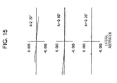
- Fig. 16 illustrates the lens configuration of a zoom lens system according to a third embodiment of the present invention.
- a first lens unit G1 is configured of a cemented lens L11 of a negative meniscus lens having a convex surface facing the object and a positive lens having convex surface facing the object, and a positive lens L12 having a convex lens facing the object;
- a second lens unit G2 is configured of a negative meniscus lens L21 having a concave surface facing the image, a negative lens L22 whose surfaces are both concave, and a lens L23 whose surfaces are both convex;
- a third lens unit G3 is configured of a positive lens having an aspherical surface facing the object and shoes surfaces are both convex;
- a fourth lens unit G4 configured of a cemented lens L4 of a positive meniscus lens having an aspherical surface facing the object and a convex surface having the image and a negative meniscus lens having a concave surface facing the object;
- the negative lens L51 in the fifth lens unit G5 functions as a negative subunit and the cemented lens L52 functions as a positive subunit.
- the cemented lens L52 is shifted in a direction substantially orthogonal to the optical axis.
- An aperture stop S is provided close to the object side of the third lens unit G3 and moves together with the third lens unit G3 when carrying out magnification.
- a low-pass filter LPF is disposed between the fifth lens unit G5 and an image plane IMG.
- Table 9 shows data according to a third numerical example obtained by applying specific numerical values to the third embodiment.
- the 13th surface, the 15th surface, and the 20th surface are aspherical surfaces.
- Table 10 shows aspherical surface coefficients A, B, C, and D of the 4th, 6th, 8th, and 10th orders and the cone constant ⁇ of the 13th surface, the 15th surface, and the 20th surface in the third numerical example.
- the surface distance D5 between the first lens unit G1 and the second lens unit G2, the surface distance D11 between the second lens unit G2 and the aperture stop S, the surface distance D14 between the third lens unit G3 and the fourth lens unit G4, and the surface distance D17 between the fourth lens unit G4 and the fifth lens unit G5 change.
- Table 12 shows values of the third numerical example corresponding to Expressions 1 to 4, described above.
- /Dn 0.961
- the solid line in the spherical aberration diagram represents spherical aberration
- the solid line in the astigmatism diagram represents the sagittal image plane
- the dotted line in the astigmatism diagram represents the meridional image plane.
- A represents the angle of view and y represents the image height.
- Fig. 28 illustrates an image-pickup apparatus according to an embodiment of the present invention.
- An image-pickup apparatus 10 includes a zoom lens system 20 and an image-pickup element 30 configured to convert an optical image formed by the zoom lens system 20 into an electric signal.
- a photoelectric conversion element such as a charge coupled device (CCD) or a complementary metal-oxide semiconductor (CMOS1)
- CCD charge coupled device
- CMOS1 complementary metal-oxide semiconductor
- the zoom lens system 20 a zoom lens system according to an embodiment of the present invention may be employed.
- the lens units included in the zoom lens system 1 according t the first embodiment, shown in Fig. 1 is simplified and shown as a single lens.
- the zoom lens system to be employed is not limited to the zoom lens system 1 according to the first embodiment, and, instead, the zoom lens system 2 or 3 according to the second or third embodiment or any other zoom lens systems according to an embodiment of the present invention not described in this specification may be employed.
- An electric signal generated by the image-pickup element 30 is sent to an image separation circuit 40.
- a signal for focus control is sent to a control circuit 50 and a signal for image is sent to an image-processing circuit.
- the signal sent to the image-processing circuit is converted into various signals suitable for the subsequent processing.
- the converted signals are subjected to various types of processing, such as display by a display apparatus, recording on a recoding medium, or transferring by a communication device.
- an operation signal such as an operation signal of a zoom button
- an operation signal is input to the control circuit 50 from an outside unit, and various types of processing is carried out depending on the operation signal.
- driving units 61, 62, 63, and 64 are operated via a driver circuit 60 so as to set the focal distance on the basis of the instruction, and lens unit G1, G2, G3, and G4 are moved to predetermined positions.
- Position information of the lens units G1, G2, G3, and G4 obtained by sensors 71, 72, 73, and 74 is input to the control circuit 50 and is referred to when outputting an instruction signal to the driver circuit 60.
- the control circuit 50 checks the focus condition on the basis of the signal sent from the image separation circuit 40, operates the driving unit 64 via the driver circuit 60 so as to obtain an optimal focus condition, and controls the position of the fourth lens unit G4.
- the image-pickup apparatus 10 includes a shake-correction function.
- a shake detection unit 80 e.g., a gyro sensor
- detects shaking of the image-pickup element caused by pressing the shutter release button a signal is sent from the shake detection unit 80 to the control circuit 50.
- a shake-correction angle for compensating for the shaking of the image is calculated.
- the control circuit 50 operates a driving unit 91 via a driver circuit 90 so as to move a positive subunit L52 of the fifth lens unit G5 on the basis of the calculated shake-correction angle and moves the positive subunit L52 in a direction orthogonal to the optical axis.
- control circuit 50 functions as a shake-control unit
- driving unit 91 functions as a shake-driving unit.
- the position of the positive subunit L52 is detected by a sensor 92.
- the position information of the positive subunit L52 obtained by the sensor 92 is input to the control circuit 50 and is referred to when an instruction signal is sent to the driver circuit 90.
- the image-pickup apparatus 10 may be provided as various different specific products.
- the image-pickup apparatus 10 may be employed as a camera unit of a digital input/output device, such as a digital still camera, digital video camera, a mobile phone having a camera, and a personal digital assistant (PDA) having a camera.
- a digital input/output device such as a digital still camera, digital video camera, a mobile phone having a camera, and a personal digital assistant (PDA) having a camera.
- PDA personal digital assistant
Landscapes
- Physics & Mathematics (AREA)
- General Physics & Mathematics (AREA)
- Optics & Photonics (AREA)
- Engineering & Computer Science (AREA)
- Multimedia (AREA)
- Signal Processing (AREA)
- Lenses (AREA)
- Lens Barrels (AREA)
- Adjustment Of Camera Lenses (AREA)
Applications Claiming Priority (1)
| Application Number | Priority Date | Filing Date | Title |
|---|---|---|---|
| JP2006033767A JP2007212846A (ja) | 2006-02-10 | 2006-02-10 | ズームレンズ及び撮像装置 |
Publications (2)
| Publication Number | Publication Date |
|---|---|
| EP1818708A2 true EP1818708A2 (de) | 2007-08-15 |
| EP1818708A3 EP1818708A3 (de) | 2008-09-03 |
Family
ID=38016603
Family Applications (1)
| Application Number | Title | Priority Date | Filing Date |
|---|---|---|---|
| EP07102029A Withdrawn EP1818708A3 (de) | 2006-02-10 | 2007-02-09 | Zoomobjektiv und Bildaufnahmevorrichtung |
Country Status (6)
| Country | Link |
|---|---|
| US (1) | US7554744B2 (de) |
| EP (1) | EP1818708A3 (de) |
| JP (1) | JP2007212846A (de) |
| KR (1) | KR20070081425A (de) |
| CN (1) | CN101017237A (de) |
| TW (1) | TW200745599A (de) |
Families Citing this family (18)
| Publication number | Priority date | Publication date | Assignee | Title |
|---|---|---|---|---|
| US6827977B2 (en) * | 2002-03-07 | 2004-12-07 | Guardian Industries Corp. | Method of making window unit including diamond-like carbon (DLC) coating |
| JP4591780B2 (ja) * | 2006-02-13 | 2010-12-01 | ソニー株式会社 | 可変焦点距離レンズ系及び撮像装置 |
| US7986458B2 (en) | 2007-12-26 | 2011-07-26 | Sony Corporation | Zoom lens and image pickup apparatus |
| KR101462958B1 (ko) * | 2008-08-06 | 2014-11-19 | 삼성전자주식회사 | 소형 줌 광학계 |
| JP2010049112A (ja) * | 2008-08-22 | 2010-03-04 | Sanyo Electric Co Ltd | レンズ装置、撮影装置 |
| JP5495655B2 (ja) * | 2009-08-03 | 2014-05-21 | キヤノン株式会社 | ズームレンズ及びそれを有する撮像装置 |
| US8339713B2 (en) * | 2009-11-04 | 2012-12-25 | Nikon Corporation | Zoom optical system, optical apparatus and method for manufacturing zoom optical system |
| JP5528211B2 (ja) * | 2010-05-24 | 2014-06-25 | キヤノン株式会社 | ズームレンズ及びそれを有する撮像装置 |
| JP5566207B2 (ja) | 2010-07-14 | 2014-08-06 | キヤノン株式会社 | ズームレンズ及びそれを有する撮像装置 |
| JP2012088618A (ja) * | 2010-10-21 | 2012-05-10 | Sony Corp | ズームレンズおよび撮像装置 |
| TWI436123B (zh) * | 2010-12-28 | 2014-05-01 | Asia Optical Co Inc | Miniature zoom lens |
| CN103048768B (zh) * | 2011-10-14 | 2016-12-21 | 鸿富锦精密工业(深圳)有限公司 | 镜头系统 |
| US8867143B2 (en) * | 2011-11-16 | 2014-10-21 | Canon Kabushiki Kaisha | Zoom lens and image pickup apparatus including the same |
| WO2014069448A1 (ja) * | 2012-10-30 | 2014-05-08 | 株式会社ニコン | 変倍光学系、光学装置、変倍光学系の製造方法 |
| WO2015015792A1 (ja) * | 2013-07-29 | 2015-02-05 | 株式会社ニコン | 変倍光学系、光学装置及び変倍光学系の製造方法 |
| CN106461921B (zh) * | 2014-04-21 | 2019-03-26 | 株式会社尼康 | 变倍光学系统以及光学设备 |
| JP7140136B2 (ja) * | 2017-10-17 | 2022-09-21 | ソニーグループ株式会社 | 可変焦点距離レンズ系および撮像装置 |
| CN111147741B (zh) * | 2019-12-27 | 2021-08-13 | Oppo广东移动通信有限公司 | 基于对焦处理的防抖方法和装置、电子设备、存储介质 |
Citations (3)
| Publication number | Priority date | Publication date | Assignee | Title |
|---|---|---|---|---|
| JPH05224160A (ja) * | 1992-02-14 | 1993-09-03 | Canon Inc | 防振機能を有した変倍光学系 |
| US5623364A (en) * | 1994-06-07 | 1997-04-22 | Olympus Optical Co., Ltd. | Vibration-proof optical system |
| JP2001228397A (ja) * | 2000-02-14 | 2001-08-24 | Olympus Optical Co Ltd | ズームレンズ |
Family Cites Families (6)
| Publication number | Priority date | Publication date | Assignee | Title |
|---|---|---|---|---|
| JP4288408B2 (ja) | 2003-02-20 | 2009-07-01 | 株式会社ニコン | 像シフト可能なズームレンズ |
| JP2005128186A (ja) | 2003-10-22 | 2005-05-19 | Matsushita Electric Ind Co Ltd | ズームレンズ、並びにそれを用いたビデオカメラ及びデジタルスチルカメラ |
| JP4532916B2 (ja) | 2004-01-30 | 2010-08-25 | キヤノン株式会社 | ズームレンズ及びそれを有する撮像装置 |
| JP4585776B2 (ja) * | 2004-02-26 | 2010-11-24 | キヤノン株式会社 | ズームレンズ及びそれを有する撮像装置 |
| JP2006071993A (ja) * | 2004-09-02 | 2006-03-16 | Sony Corp | ズームレンズ及び撮像装置 |
| JP2006301474A (ja) * | 2005-04-25 | 2006-11-02 | Sony Corp | ズームレンズ及び撮像装置 |
-
2006
- 2006-02-10 JP JP2006033767A patent/JP2007212846A/ja not_active Abandoned
-
2007
- 2007-01-30 US US11/699,413 patent/US7554744B2/en not_active Expired - Fee Related
- 2007-02-01 KR KR1020070010546A patent/KR20070081425A/ko not_active Application Discontinuation
- 2007-02-01 TW TW096103710A patent/TW200745599A/zh unknown
- 2007-02-09 EP EP07102029A patent/EP1818708A3/de not_active Withdrawn
- 2007-02-12 CN CNA2007100052152A patent/CN101017237A/zh active Pending
Patent Citations (3)
| Publication number | Priority date | Publication date | Assignee | Title |
|---|---|---|---|---|
| JPH05224160A (ja) * | 1992-02-14 | 1993-09-03 | Canon Inc | 防振機能を有した変倍光学系 |
| US5623364A (en) * | 1994-06-07 | 1997-04-22 | Olympus Optical Co., Ltd. | Vibration-proof optical system |
| JP2001228397A (ja) * | 2000-02-14 | 2001-08-24 | Olympus Optical Co Ltd | ズームレンズ |
Also Published As
| Publication number | Publication date |
|---|---|
| US20070188887A1 (en) | 2007-08-16 |
| KR20070081425A (ko) | 2007-08-16 |
| JP2007212846A (ja) | 2007-08-23 |
| TW200745599A (en) | 2007-12-16 |
| CN101017237A (zh) | 2007-08-15 |
| EP1818708A3 (de) | 2008-09-03 |
| US7554744B2 (en) | 2009-06-30 |
Similar Documents
| Publication | Publication Date | Title |
|---|---|---|
| US7554744B2 (en) | Zoom lens system and image-pickup apparatus | |
| EP1736814B1 (de) | Zoomobjektiv und Bildaufnahmevorrichtung | |
| JP4655205B2 (ja) | ズームレンズ及び撮像装置 | |
| JP4591780B2 (ja) | 可変焦点距離レンズ系及び撮像装置 | |
| JP4264581B2 (ja) | 可変焦点距離レンズ系及び撮像装置 | |
| EP1780578B1 (de) | Zoomobjektiv und Abbildungsgerät mit Vibrationskompensation | |
| EP1865352B1 (de) | Telezoomobjektiv mit sechs Linsengruppen | |
| EP1717625B1 (de) | Telezoomobjektiv mit sechs Linsengruppen | |
| JP4650676B2 (ja) | ズームレンズ及び撮像装置 | |
| EP1780579B1 (de) | Telezoomobjektiv mit einem bildseitigen Prisma mit variablem Spitzenwinkel | |
| JP2005352183A (ja) | 可変焦点距離レンズ系及び撮像装置 | |
| JP4210935B2 (ja) | 可変焦点距離レンズ系及び撮像装置 | |
| JP4961710B2 (ja) | ズームレンズ及び撮像装置 | |
| JP4441856B2 (ja) | 可変焦点距離レンズ系及び撮像装置 | |
| JP2006259215A (ja) | ズームレンズ及び撮像装置 | |
| JP4587028B2 (ja) | ズームレンズ | |
| JP4935034B2 (ja) | ズームレンズ及び撮像装置 | |
| JP4775672B2 (ja) | ズームレンズ及び撮像装置 | |
| JP2007127694A (ja) | ズームレンズ及び撮像装置 |
Legal Events
| Date | Code | Title | Description |
|---|---|---|---|
| PUAI | Public reference made under article 153(3) epc to a published international application that has entered the european phase |
Free format text: ORIGINAL CODE: 0009012 |
|
| AK | Designated contracting states |
Kind code of ref document: A2 Designated state(s): AT BE BG CH CY CZ DE DK EE ES FI FR GB GR HU IE IS IT LI LT LU LV MC NL PL PT RO SE SI SK TR |
|
| AX | Request for extension of the european patent |
Extension state: AL BA HR MK YU |
|
| PUAL | Search report despatched |
Free format text: ORIGINAL CODE: 0009013 |
|
| AK | Designated contracting states |
Kind code of ref document: A3 Designated state(s): AT BE BG CH CY CZ DE DK EE ES FI FR GB GR HU IE IS IT LI LT LU LV MC NL PL PT RO SE SI SK TR |
|
| AX | Request for extension of the european patent |
Extension state: AL BA HR MK RS |
|
| 17P | Request for examination filed |
Effective date: 20090223 |
|
| 17Q | First examination report despatched |
Effective date: 20090327 |
|
| AKX | Designation fees paid |
Designated state(s): AT BE BG CH CY CZ DE DK EE ES FI FR GB GR HU IE IS IT LI LT LU LV MC NL PL PT RO SE SI SK TR |
|
| STAA | Information on the status of an ep patent application or granted ep patent |
Free format text: STATUS: THE APPLICATION IS DEEMED TO BE WITHDRAWN |
|
| 18D | Application deemed to be withdrawn |
Effective date: 20090807 |