EP1818707A1 - Variable focal length lens system and image capturing apparatus - Google Patents
Variable focal length lens system and image capturing apparatus Download PDFInfo
- Publication number
- EP1818707A1 EP1818707A1 EP07102185A EP07102185A EP1818707A1 EP 1818707 A1 EP1818707 A1 EP 1818707A1 EP 07102185 A EP07102185 A EP 07102185A EP 07102185 A EP07102185 A EP 07102185A EP 1818707 A1 EP1818707 A1 EP 1818707A1
- Authority
- EP
- European Patent Office
- Prior art keywords
- lens
- lens group
- focal length
- variable focal
- negative
- Prior art date
- Legal status (The legal status is an assumption and is not a legal conclusion. Google has not performed a legal analysis and makes no representation as to the accuracy of the status listed.)
- Withdrawn
Links
Images


Classifications
-
- G—PHYSICS
- G02—OPTICS
- G02B—OPTICAL ELEMENTS, SYSTEMS OR APPARATUS
- G02B15/00—Optical objectives with means for varying the magnification
- G02B15/14—Optical objectives with means for varying the magnification by axial movement of one or more lenses or groups of lenses relative to the image plane for continuously varying the equivalent focal length of the objective
- G02B15/145—Optical objectives with means for varying the magnification by axial movement of one or more lenses or groups of lenses relative to the image plane for continuously varying the equivalent focal length of the objective having five groups only
- G02B15/1451—Optical objectives with means for varying the magnification by axial movement of one or more lenses or groups of lenses relative to the image plane for continuously varying the equivalent focal length of the objective having five groups only the first group being positive
- G02B15/145113—Optical objectives with means for varying the magnification by axial movement of one or more lenses or groups of lenses relative to the image plane for continuously varying the equivalent focal length of the objective having five groups only the first group being positive arranged +-++-
-
- G—PHYSICS
- G02—OPTICS
- G02B—OPTICAL ELEMENTS, SYSTEMS OR APPARATUS
- G02B13/00—Optical objectives specially designed for the purposes specified below
- G02B13/001—Miniaturised objectives for electronic devices, e.g. portable telephones, webcams, PDAs, small digital cameras
- G02B13/009—Miniaturised objectives for electronic devices, e.g. portable telephones, webcams, PDAs, small digital cameras having zoom function
-
- G—PHYSICS
- G02—OPTICS
- G02B—OPTICAL ELEMENTS, SYSTEMS OR APPARATUS
- G02B15/00—Optical objectives with means for varying the magnification
- G02B15/14—Optical objectives with means for varying the magnification by axial movement of one or more lenses or groups of lenses relative to the image plane for continuously varying the equivalent focal length of the objective
- G02B15/145—Optical objectives with means for varying the magnification by axial movement of one or more lenses or groups of lenses relative to the image plane for continuously varying the equivalent focal length of the objective having five groups only
- G02B15/1451—Optical objectives with means for varying the magnification by axial movement of one or more lenses or groups of lenses relative to the image plane for continuously varying the equivalent focal length of the objective having five groups only the first group being positive
- G02B15/145129—Optical objectives with means for varying the magnification by axial movement of one or more lenses or groups of lenses relative to the image plane for continuously varying the equivalent focal length of the objective having five groups only the first group being positive arranged +-+++
-
- G—PHYSICS
- G02—OPTICS
- G02B—OPTICAL ELEMENTS, SYSTEMS OR APPARATUS
- G02B3/00—Simple or compound lenses
- G02B3/0087—Simple or compound lenses with index gradient
-
- G—PHYSICS
- G03—PHOTOGRAPHY; CINEMATOGRAPHY; ANALOGOUS TECHNIQUES USING WAVES OTHER THAN OPTICAL WAVES; ELECTROGRAPHY; HOLOGRAPHY
- G03B—APPARATUS OR ARRANGEMENTS FOR TAKING PHOTOGRAPHS OR FOR PROJECTING OR VIEWING THEM; APPARATUS OR ARRANGEMENTS EMPLOYING ANALOGOUS TECHNIQUES USING WAVES OTHER THAN OPTICAL WAVES; ACCESSORIES THEREFOR
- G03B17/00—Details of cameras or camera bodies; Accessories therefor
- G03B17/02—Bodies
- G03B17/12—Bodies with means for supporting objectives, supplementary lenses, filters, masks, or turrets
-
- H—ELECTRICITY
- H04—ELECTRIC COMMUNICATION TECHNIQUE
- H04N—PICTORIAL COMMUNICATION, e.g. TELEVISION
- H04N23/00—Cameras or camera modules comprising electronic image sensors; Control thereof
- H04N23/50—Constructional details
- H04N23/55—Optical parts specially adapted for electronic image sensors; Mounting thereof
-
- G—PHYSICS
- G02—OPTICS
- G02B—OPTICAL ELEMENTS, SYSTEMS OR APPARATUS
- G02B7/00—Mountings, adjusting means, or light-tight connections, for optical elements
- G02B7/02—Mountings, adjusting means, or light-tight connections, for optical elements for lenses
- G02B7/04—Mountings, adjusting means, or light-tight connections, for optical elements for lenses with mechanism for focusing or varying magnification
- G02B7/10—Mountings, adjusting means, or light-tight connections, for optical elements for lenses with mechanism for focusing or varying magnification by relative axial movement of several lenses, e.g. of varifocal objective lens
- G02B7/102—Mountings, adjusting means, or light-tight connections, for optical elements for lenses with mechanism for focusing or varying magnification by relative axial movement of several lenses, e.g. of varifocal objective lens controlled by a microcomputer
Definitions
- the present invention generally relates to a variable focal length lens system and an image capturing apparatus including the variable focal length lens system and, in particular, to a variable focal length lens system having a zoom ratio greater than 10 and an image capturing apparatus, such as a video camera or a digital still camera, including the variable focal length lens system.
- CMOS complementary metal-oxide semiconductors
- the increased density and decreased size of the light receiving elements reduce the light receiving area of each of the photoelectric transducers, and therefore, the intensity of the electrical output is decreased.
- the effect of noise on the electrical output increases.
- an amount of light received by the light receiving element is increased by increasing the aperture ratio of an optical system or by mounting a microlens element immediately before each of the light receiving elements, forming what is known as a "microlens array".
- the microlens array leads a light ray between the neighboring light receiving elements to the light receiving elements, the microlens array imposes a constraint on the position of the exit pupil of a lens system.
- the angle between the light ray and the optical axis of a chief light ray that reaches the light receiving element is large
- the angle between an off-axis ray propagating towards the periphery of a screen and the optical axis is made to be large.
- the off-axis ray does not reach the light receiving element, and therefore, an insufficient amount of light is received.
- a zoom lens having a variable magnification ratio greater than 10 allows a camera to capture a significantly magnified image of a subject.
- some users require a lens system of a high variable magnification ratio even though the size of the body of the camera is increased.
- Japanese Unexamined Patent Application Publication No. 2005-215385 Japanese Unexamined Patent Application Publication No. 2003-295059
- Japanese Unexamined Patent Application Publication No. 2005-128186 describe zoom lenses having a variable magnification ratio more than 10.
- the zoom lenses described in Japanese Unexamined Patent Application Publication Nos. 2005-215385 and 2003-295059 include a first lens group having a positive refractive power, a second lens group having a negative refractive power, a third lens group having a positive refractive power, and a fourth lens group having a positive refractive power in this order from the object side.
- the lens zoom position changes from a wide-angle position to a telephoto position
- the first lens group is moved towards the object side
- the second lens group is moved towards the image plane side
- the third lens group is temporarily moved towards the object side and, subsequently, is moved towards the object side
- the fourth lens group is temporarily moved towards the object side and, subsequently, is moved towards the image plane side.
- an aperture stop located between the second lens group and the third lens group can be moved independently from the other lens groups.
- the zoom lens described in Japanese Unexamined Patent Application Publication No. 2005-128186 includes a first lens group having a positive refractive power, a second lens group having a negative refractive power, a third lens group having a positive refractive power, and a fourth lens group having a positive refractive power in this order from the object side.
- the first and third lens groups are stationary in the optical axis direction
- the second lens group is moved towards the image-plane side
- the fourth lens group is moved so as to compensate for the change in the position of the image plane due to the movement of the second lens group.
- the variation in off-axis aberration occurring in the second lens group is significant in accordance with the change in the lens zoom position. Accordingly, it is difficult to achieve a high variable magnification and a high performance at the same time.
- the third lens group has a strong positive refractive power
- the third lens group needs to include a positive subgroup having a positive refractive power and a negative subgroup having a negative refractive power.
- the third lens group has a strong refractive power.
- the third lens group since only the second lens group has a negative refractive power, the third lens group includes a positive subgroup having a positive refractive power and a negative subgroup having a negative refractive power so as to sufficiently correct a negative distortion which tends to occur at the wide-angle position.
- the positive subgroup disposed in the third lens group has a strong refractive power. At the same time, the performance significantly deteriorates since the negative subgroup and the positive subgroup become eccentric.
- the present invention provides a variable focal length lens system that can provide a high performance and a high variable magnification at the same time and an image capturing apparatus including the variable focal length lens system.
- a variable focal length lens system includes a first lens group having a positive refractive power, a second lens group having a negative refractive power, a third lens group having a positive refractive power, a fourth lens group having a positive refractive power, and a fifth lens group arranged in this order from an object side to an image plane side.
- At least the first to fourth lens groups are movable and the second lens group is moved towards the image plane side and the third lens group is moved towards the object side so that a distance between the first lens group and the second lens group increases and a distance between the second lens group and the third lens group decreases, and the fourth lens group is moved along an optical axis direction so as to compensate for the change in the position of the image plane caused by the movement of each lens group.
- the fifth lens group includes a negative subgroup having a negative refractive power and a positive subgroup disposed on the image plane side of the negative subgroup and having a positive refractive power, and the following conditional expression (1) is satisfied: 0.5 ⁇ ⁇ ⁇ 2 ⁇ t / ⁇ ⁇ 2 ⁇ w / Z ⁇ 0.85 where
- an image capturing apparatus includes the above-described variable focal length lens system and an image sensor for converting an optical image formed through the variable focal length lens system to an electrical signal.
- variable focal length lens system that can provide a high optical performance and a high variable magnification at the same time and an image capturing apparatus including the variable focal length lens system can be achieved.
- variable focal length lens systems of the present invention can be achieved by the following first to sixth exemplary embodiments.
- a zoom lens according to a first exemplary embodiment includes a first lens group having a positive refractive power, a second lens group having a negative refractive power, a third lens group having a positive refractive power, a fourth lens group having a positive refractive power, and a fifth lens group arranged in this order from the object side.
- a lens zoom position is changed from a wide-angle position at which the focal length is minimum to a telephoto position at which the focal length is maximum, at least the first to fourth lens groups are movable.
- the second lens group is moved towards the image-plane side and the third lens group is moved towards the object side so that the distance between the first lens group and the second lens groups is increased and the distance between the second lens group and the third lens groups is decreased.
- the fourth lens group is moved in the optical axis direction so as to compensate for the change in the position of the image plane due to the movements of the lens groups.
- the fifth lens group includes a negative subgroup having a negative refractive power and a positive subgroup disposed on the image-plane side of the negative subgroup and having a positive refractive power.
- conditional expression is satisfied: 0.5 ⁇ ⁇ ⁇ 2 ⁇ t / ⁇ ⁇ 2 ⁇ w / Z ⁇ 0.85
- variable focal length lens system can provide a high variable magnification and a high performance at the same time by reducing the level of responsibility imposed on the second lens group in performing variable magnification.
- a variable focal length lens system is similar to the variable focal length lens system according to the first exemplary embodiment.
- f5n denote the focal length of the negative subgroup included in the fifth lens group
- fw denote the focal length of the whole lens system at the wide-angle position. Then, the variable focal length lens system further satisfies the following conditional expression: 2.5 ⁇ f ⁇ 5 ⁇ n / fw ⁇ 5
- the performance can be further increased.
- a variable focal length lens system is similar to the variable focal length lens system according to the first embodiment or the second embodiment.
- the fifth lens group is stationary in the optical axis direction regardless of the lens zoom position.
- the lens barrel structure can be simplified.
- a variable focal length lens system is similar to the variable focal length lens system according to the first embodiment or the second embodiment.
- an aperture stop is disposed adjacent to the third lens group.
- Dsw denote a distance between the aperture stop and the image plane at the wide-angle position
- TLw denote the total length of the lens system at the wide-angle position.
- the variable focal length lens system further satisfies the following conditional expression: 0.3 ⁇ Dsw / TLw ⁇ 0.4
- variable focal length lens system is similar to the variable focal length lens system according to the first embodiment or the second embodiment. However, the variable focal length lens system further satisfies the following conditional expression: 0.25 ⁇ 1 / ⁇ ⁇ 2 ⁇ t ⁇ 0.45
- the performance can be further increased.
- a variable focal length lens system is similar to the variable focal length lens system according to the first embodiment or the second embodiment.
- R5n denote the radius of curvature of the lens surface of a lens included in the negative lens subgroup of the fifth lens group and located closest to the image plane
- Bf denote the distance between a lens included in the positive lens subgroup of the fifth lens group and located closest to the image plane and the image plane.
- the variable focal length lens system further satisfies the following conditional expression: 0.8 ⁇ R ⁇ 5 ⁇ n / Bf ⁇ 1.5
- the performance can be further increased.
- the image capturing apparatuses of the present invention can be achieved by the following seventh to eighth exemplary embodiments.
- an image capturing apparatus includes a variable focal length lens system and an image pickup device that converts an optical image formed by the variable focal length lens system to an electrical signal.
- the variable focal length lens system includes a first lens group having a positive refractive power, a second lens group having a negative refractive power, a third lens group having a positive refractive power, and a fourth lens group having a positive refractive power, and a fifth lens group arranged in this order from the object side.
- the second lens group is moved towards the image-plane side and the third lens group is moved towards the object side so that the distance between the first lens group and the second lens groups is increased and the distance between the second lens group and the third lens groups is decreased.
- the fourth lens group is moved in the optical axis direction so as to compensate for the change in the position of the image plane due to the movements of the lens groups.
- the fifth lens group includes a negative subgroup having a negative refractive power and a positive subgroup disposed on the image-plane side of the negative subgroup and having a positive refractive power.
- the following conditional expression is satisfied: 0.5 ⁇ ⁇ ⁇ 2 ⁇ t / ⁇ ⁇ 2 ⁇ w / Z ⁇ 0.85
- a high-quality image can be captured using a high magnification ratio.
- an image capturing apparatus is similar to the image capturing apparatus according to the seventh exemplary embodiment.
- f5n denote the focal length of the negative subgroup included in the fifth lens group
- fw denote the focal length of the whole lens system at the wide-angle position. Then, the following conditional expression is satisfied: 2.5 ⁇ f ⁇ 5 ⁇ n / fw ⁇ 5
- the performance of the image capturing apparatus can be further increased.
- variable focal length lens system and the image capturing apparatus have been described in conjunction with the above-described exemplary embodiments, it will be understood that they are not intended to limit the invention to these embodiments. On the contrary, the invention is intended to cover alternatives, modifications and equivalents, which may be included within the spirit and scope of the invention.
- variable focal length lens system is described in more detail next.
- the variable focal length lens system includes a first lens group having a positive refractive power, a second lens group having a negative refractive power, a third lens group having a positive refractive power, and a fourth lens group having a positive refractive power, and a fifth lens group arranged in this order from the object side.
- At least first to fourth lens groups are movable.
- the second lens group is moved towards the image-plane side and the third lens group is moved towards the object side so that the distance between the first lens group and the second lens groups is increased and the distance between the second lens group and the third lens group is decreased.
- the fourth lens group is moved in the optical axis direction so as to compensate for the change in the position of the image plane due to the movements of the lens groups.
- the fifth lens group includes a negative subgroup having a negative refractive power and a positive subgroup disposed on the image-plane side of the negative subgroup and having a positive refractive power.
- the following conditional expression is satisfied: 0.5 ⁇ ⁇ ⁇ 2 ⁇ t / ⁇ ⁇ 2 ⁇ w / Z ⁇ 0.85
- variable focal length lens system can provide a high magnification ratio and high performance at the same time. This structure is described in detail next.
- variable focal length lens system can provide a high magnification ratio and high performance at the same time by achieving the following two points:
- the level of responsibility assigned to the second lens group in performing variable magnification is reduced.
- the term "level of responsibility assigned to the second lens group in performing variable magnification” refers to ⁇ 2t/ ⁇ 2w, which is a ratio of the lateral magnification ⁇ 2t of the second lens group at the telephoto position to the lateral magnification ⁇ 2w of the second lens group at the wide-angle position.
- the ratio ⁇ 2t/ ⁇ 2w is decreased.
- the lateral magnification of the second lens group largely changes when the lens zoom position changes. That is, variations in various aberrations easily occur in accordance with the change in magnification of the variable focal length lens system.
- the ratio ⁇ 2t/ ⁇ 2w becomes higher and the change in the distance between the first lens group and the second lens group becomes larger. Accordingly, the size of the whole lens system increases. For this reason, as the magnification ratio is increased, the refractive power of the second lens group is increased. Thus, it is difficult to provide a high magnification ratio and high performance at the same time.
- variable focal length lens system actively changes the distance between the second lens group and the third lens group by moving the third lens group towards the object side. That is, the problem is solved by significantly changing the lateral magnification of the third lens group.
- a ratio ⁇ 3t/ ⁇ 3w where ⁇ 3w denotes a lateral magnification of the third lens group at a wide-angle position and ⁇ 3t denotes a lateral magnification of the third lens group at a telephoto position, increases. Accordingly, the ratio ⁇ 2t/ ⁇ 2w can be decreased, and therefore, the negative refractive power of the second lens group can be decreased. In this way, the variations in various aberrations occurring when the lens zoom position is changed can be sufficiently corrected.
- variable focal length lens systems since the fifth lens group is disposed on the image plane side of the fourth group, the lens structure of the third lens group can be simplified.
- the variable focal length lens systems can provide a high magnification ratio and high performance at the same time.
- an off-axis light ray moves farther off axis towards an end of an optical system (either end on the object side or on the image-plane side).
- the variable focal length lens systems reduces the load of the third lens group in correcting aberrations by disposing the fifth lens group on the image plane side of the fourth lens group.
- the variable focal length lens systems when the variable focal length lens systems have the fifth lens group including a negative subgroup having a negative refractive power and a positive subgroup disposed on the image plane side of the negative subgroup and having a positive refractive power, the variable focal length lens systems can reduce the load of the third lens group in correcting aberrations.
- the variable focal length lens systems can provide a high magnification ratio and reliable optical quality.
- the fifth lens group of the variable focal length lens systems has the following two features.
- One is a feature for adjusting the position of the exit pupil.
- the distance between the position of the exit pupil and the image plane can be increased by disposing the negative subgroup having a negative refractive power and a positive subgroup located on the image-plane side of the negative subgroup and having a positive refractive power with an air gap therebetween. That is, a chief ray can reach the image plane with the propagation direction thereof substantially parallel to the optical axis.
- the other is a feature for correcting distortion.
- a negative distortion that tends to occur at the wide-angle position can be sufficiently corrected by directing a strongly concave surface of a lens of the negative subgroup having a negative refractive power towards the image-plane side.
- variable focal length lens systems can increase the range of the position of the exit pupil of a lens system disposed on the object side of the fifth lens group.
- an angle between a chief ray exiting the third lens group and the optical axis can be freely determined.
- the third lens group need not correct the negative distortion, and therefore, the third lens group can be composed of only a positive subgroup. Consequently, the structure of the third lens group can be simplified.
- variable focal length lens systems can provide a high magnification ratio and high performance at the same time.
- conditional expression (1) defines the range of the change in the lateral magnification ratio of the second lens group when the lens zoom position is changed.
- variable focal length lens systems satisfy the following conditional expression: 2.5 ⁇ f ⁇ 5 ⁇ n / fw ⁇ 5 where
- Conditional expression (2) defines the range of the focal length of the negative subgroup disposed in the fifth lens group.
- the fifth lens group is stationary in the optical axis direction regardless of the lens zoom position.
- the aperture stop of the variable focal length lens systems is disposed in the vicinity of the third lens group.
- an off-axis ray passes through the lens at a position farther from the optical axis. Therefore, it is desirable that the aperture stop is disposed exactly at the center point of the lens system or in the vicinity of the center point.
- the height of the off-axis ray passing through each of the lens groups needs to be significantly changed when the lens zoom position is changed.
- variable focal length lens systems since the aperture stop is disposed in the vicinity of the third lens group, the distance between the optical axis and the off-axis ray passing through the second lens group is decreased when the lens zoom position of the variable focal length lens systems is changed from the wide-angle position to the telephoto position.
- the height of the off-axis ray passing through the first and fourth lens groups is changed, and therefore, the performance of the variable focal length lens systems can be improved.
- variable focal length lens systems can reduce the diameter of the lens and improve the performance thereof by satisfying the following conditional expression: 0.3 ⁇ Dsw / TLw ⁇ 0.4
- Conditional expression (3) determines the position of the aperture stop at the wide-angle position.
- variable focal length lens systems according to the exemplary embodiments of the present invention, the aperture stop is moved together with the third lens group.
- the structure of the lens barrel can be simplified.
- the fourth lens group is moved in the optical axis direction when focusing on an object a very short distance from the variable focal length lens system.
- the lateral magnification of the second lens group should be in the range between -1 and 0 regardless of the lens zoom position. This is because the variable focal length lens system cannot focus on an object a very short distance from the variable focal length lens system at a lens zoom position at which the lateral magnification of the second lens group is -1 and, if the lateral magnification of the second lens group is less than -1, the moving direction is reversed.
- the zoom ratio is higher, the lateral magnification of the second lens group at a wide-angle position is closer to zero. That is, since the refractive power of the second lens group is increased, it is difficult to sufficiently correct the variation of the off-axis aberrations caused by the change in the angle of field at the wide-angle position.
- variable focal length lens systems move the fourth lens group when focusing on an object a very short distance from the variable focal length lens system.
- the constraint imposed on the lateral magnification of the second lens group is removed.
- the lateral magnification of the second lens group ranges between -1 and 0 at the wide-angle position and is less than or equal to -1 at the telephoto position.
- the position at which the image is life-size i.e., the magnification is -1) is present between the wide-angle position and the telephoto position.
- the moving direction of the fourth lens group at the wide-angle position is opposite that at the telephoto position. Therefore, at the telephoto position, the distance between the third lens group and the fourth lens group is increased.
- the moving distance of the fourth lens group at the telephoto position is significantly greater than that at the wide-angle position. Accordingly, by maintaining a large distance between the third lens group and the fourth lens group at the telephoto position, the use efficiency of space can be increased when focusing on an object a very short distance from the variable focal length lens system at the telephoto position.
- the moving range of the fourth lens group i.e., the range required for compensating for the change in the lens zoom position and the change in the position of the object
- a drive mechanism of the fourth lens group can be simplified.
- variable focal length lens systems satisfy the following conditional expression: 0.25 ⁇ 1 / ⁇ ⁇ 2 ⁇ t ⁇ 0.45
- Conditional expression (4) determines the lateral magnification of the second lens group at the telephoto position.
- variable focal length lens systems in order to reduce the diameter of the lenses of the first lens group, it is desirable that the lower limit of conditional expression (4) is 0.31.
- variable focal length lens systems in order to further improve the performance, it is desirable that the following conditional expression is satisfied: 0.8 ⁇ R ⁇ 5 ⁇ n / Bf ⁇ 1.5 where
- R5n the radius of curvature of the lens surface of a lens included in the negative lens subgroup of the fifth lens group and located closest to the image plane
- Bf the distance between a lens included in the positive lens subgroup of the fifth lens group and located closest to the image plane and the image plane.
- Conditional expression (5) determines the radius of curvature of the lens surface of a lens included in the negative lens subgroup of the fifth lens group and located closest to the image plane.
- the first lens group includes the following three lenses: a negative lens and a positive lens that form a cemented lens and a positive lens arranged in this order from the object side to the image plane side.
- variable focal length lens systems since the cemented lens composed of a negative lens and a positive lens is disposed at a position closest to the object in the first lens group, the negative spherical aberration and axial chromatic aberration can be sufficiently corrected.
- the positive lens disposed on the image plane side in the cemented lens can primarily and sufficiently correct the variation in coma aberration caused by the change in the angle of field. In this way, by clearly defining the function of each of the lenses, a high optical performance can be realized.
- the second lens group is composed of the following three lenses: a negative meniscus lens having a concave surface on the image plane side, a negative lens, and a positive lens arranged in this order from the object side.
- the second lens group Since the second lens group is responsible for a variable magnification, it is important that various aberrations occurring in the second lens group are sufficiently corrected in order to improve the performance.
- the negative meniscus lens having a concave surface on the image plane side and disposed closest to the object in the second lens group sufficiently corrects the variation in coma aberration caused by the change in the angle of field at the wide-angle position.
- a doublet lens disposed on the image plane side of the negative meniscus lens sufficiently corrects the axial aberration. Accordingly, the function of each lens in terms of aberration correction is clearly defined, and therefore, an excellent image-forming performance can be provided.
- the fourth lens group is composed of a positive lens having a convex surface on the object side and a negative lens having a concave surface on the image plane side arranged in this order from the object side.
- the fourth lens group having a doublet structure can correct off-axis aberrations and axial aberrations at the same time, and therefore, the variations in various aberrations occurring when the lens zoom position changes can be sufficiently corrected.
- the first lens group is formed of a lens material having high extraordinary dispersion characteristics.
- variable focal length lens systems when an aspheric lens is used, the optical performance can be further improved.
- the optical performance in the central portion of a screen can be further improved.
- the second lens group when the second lens group includes an aspheric lens, the variation in coma aberration due to the angle of field at the wide-angle position can be sufficiently corrected.
- the optical performance can be further improved.
- a low-pass filter may be disposed to prevent the occurrence of moire fringes on the image plane side of the lens system.
- an infrared-cut filter may be disposed in accordance with a spectral sensitivity characteristic of the light receiving element.
- y denotes the height from the optical axis
- ⁇ denotes the sag of the surface
- c denotes the radius of curvature
- ⁇ denotes the conic constant
- A, B, ... denote asperical coefficients.
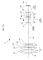
- Fig. 1 illustrates the allocation of refractive powers in the variable focal length lens systems according to the exemplary embodiments of the present invention.
- Each of the variable focal length lens systems includes a first lens group G1 having a positive refractive power, a second lens group G2 having a negative refractive power, a third lens group G3 having a positive refractive power, a fourth lens group G4 having a positive refractive power, and a fifth lens group G5 having a positive refractive power arranged in this order from the object side to the image plane side.
- the first to fourth lens groups are moved so that the air gap between the first lens group G1 and the second lens group G2 increases and the air gap between the second lens group G2 and the third lens group G3 decreases.
- the first lens group G1 is temporarily moved towards the image plane side, and subsequently, is moved towards the object side.
- the second lens group G2 is moved towards the image plane side.
- the third lens group G3 is moved towards the object side.
- the fifth lens group G5 is stationary.
- the fourth lens group G4 is moved so as to compensate for the change in the position of the image plane due to the movement of each lens group.
- the fourth lens group G4 is moved towards the object side when focusing on an object a very short distance from the variable focal length lens system.
- Fig. 2 illustrates a lens structure of the variable focal length lens system according to the first exemplary embodiment of the present invention.
- the first lens group G1 includes a cemented lens L11 composed of a negative meniscus lens having a convex surface on the object side and a positive lens having a convex surface on the object side and a positive lens L12 having a convex surface on the object side.
- the second lens group G2 includes a negative meniscus lens L21 having a concave surface on the image plane side, a negative lens L22 having two concave surfaces, and a positive meniscus lens L23 having a convex surface on the object side.
- the third lens group G3 includes a positive meniscus lens L3 having an aspherical convex surface on the object side.
- the fourth lens group G4 includes a cemented lens L4 composed of a positive lens having two convex surfaces and a negative meniscus lens having a concave surface on the object side.
- the fifth lens group G5 includes a negative meniscus lens L51 having a concave surface on the image plane side and a cemented lens L52 composed of a positive lens having two convex surfaces, one of which on the object side is aspherical, and a negative meniscus lens having a concave surface on the object side.
- the negative meniscus lens L51 forms a negative subgroup whereas the cemented lens L52 forms a positive subgroup.
- An aperture stop S is disposed close to the object side of the third lens group G3. When variable magnification is performed, the aperture stop S is moved together with the third lens group G3.
- a low-pass filter LPF is disposed between the fifth lens group G5 and an image plane IMG.
- Table 1 is a specification sheet of a first numerical embodiment in which specific values are applied to the first exemplary embodiment.
- surface number refers to the ith surface from the object side.
- radius of curvature refers to the axial radius of curvature of the surface.
- surface-surface distance refers to a distance between the ith surface and the (i+1)th surface on an optical axis.
- Abbe number refers to the Abbe number of the surface for the d-line.
- the symbol “f” denotes the focal length.
- the 13th surface and the 20th surface are aspherical. Accordingly, the fourth-order aspherical coefficients A, the sixth-order aspherical coefficients B, the eighth-order aspherical coefficients C, the tenth-order aspherical coefficients D, and the conic constants ⁇ of the 13th and 20th surfaces are shown in Table 2.
- the symbol "E-i” represents a decimal exponent, i.e., " ⁇ 10 -i ".
- "0.26029E-05" represents "0.26029 ⁇ 10 -5 ".
- a surface-surface distance D5 between the first lens group G1 and the second lens group G2, a surface-surface distance D11 between the second lens group G2 and the aperture stop S, a surface-surface distance D14 between the third lens group G3 and the fourth lens group G4, and a surface-surface distance D17 between the fourth lens group G4 and the fifth lens group G5 are changed.
- Table 4 shows values corresponding to the above-described conditional expressions (1) to (5) according to the first numerical embodiment.
- /fw 3.632 (3)
- Dsw/TLw 0.378 (4) 1/
- 0.327 (5)
- R5n/Bf 1.275
- a solid line in the spherical aberration graphs indicates the spherical aberration.
- a solid line indicates the sagittal image plane whereas a dotted line indicates the meridional image plane.
- a symbol "A" indicates the angle of field.
- a symbol "y” indicates the image height.
- variable focal length lens system has an excellent image-forming performance.
- Fig. 6 illustrates a lens structure of the variable focal length lens system according to the second exemplary embodiment of the present invention.
- the first lens group G1 includes a cemented lens L11 composed of a negative meniscus lens having a convex surface on the object side and a positive lens having a convex surface on the object side and a positive lens L12 having a convex surface on the object side.
- the second lens group G2 includes a negative meniscus lens L21 having a concave surface on the image plane side, a negative lens L22 having two concave surfaces, and a positive meniscus lens L23 having a convex surface on the object side.
- the third lens group G3 includes a positive meniscus lens L3 having an aspherical convex surface on the object side.
- the fourth lens group G4 includes a cemented lens L4 composed of a positive lens having two convex surfaces, one of which on the object side is aspherical, and a negative meniscus lens having a concave surface on the object side.
- the fifth lens group G5 includes a negative meniscus lens L51 having a concave surface on the image plane side and a cemented lens L52 composed of a positive lens having two convex surfaces and a negative meniscus lens having a concave surface on the object side.
- the negative meniscus lens L51 forms a negative subgroup whereas the cemented lens L52 forms a positive subgroup.
- An aperture stop S is disposed close to the object side of the third lens group G3. When variable magnification is performed, the aperture stop S is moved together with the third lens group G3.
- a low-pass filter LPF is disposed between the fifth lens group G5 and an image plane IMG.
- Table 5 is a specification sheet of a second numerical embodiment in which specific values are applied to the second exemplary embodiment.
- Table 5 f 1.00 ⁇ 3.20 ⁇ 14.10 F N0 2. 87 ⁇ 3.61 ⁇ 4.03 2 ⁇ 42. 89 ⁇ 23.52 ⁇ 5.39° Surface number Radius of curvature Surface-surface distance Index of refraction Abbe number 1: 14.0861 0.270 1.90366 31.1 2: 7.0926 0.923 1.49700 81.6 3: -43.0379 0.037 4: 6.6344 0.724 1.60300 65.5 5: 40.4514 (D5) 6: 33.3053 0.112 1.88300 40.8 7: 1.8894 0.762 8: -7.1286 0.130 1.88300 40.8 9: 7.6737 0.186 10: 4.3547 0.373 1.94596 18.0 11: 33.4058 (D11) 12: 0.0000 0.223 (Aperture Stop) 13: 2.7649 0.233 1.58313 59.5 14: 27.5363 (D14
- the 13th surface and the 15th surface are aspherical. Accordingly, the fourth-order aspherical coefficients A, the sixth-order aspherical coefficients B, the eighth-order aspherical coefficients C, the tenth-order aspherical coefficients D, and the conic constants ⁇ of the 13th and 15th surfaces are shown in Table 6.
- a surface-surface distance D5 between the first lens group G1 and the second lens group G2, a surface-surface distance D11 between the second lens group G2 and the aperture stop S, a surface-surface distance D14 between the third lens group G3 and the fourth lens group G4, and a surface-surface distance D17 between the fourth lens group G4 and the fifth lens group G5 are changed.
- Table 8 shows values corresponding to the above-described conditional expressions (1) to (5) according to the second numerical embodiment.
- /f w 4.036 (3)
- Dsw/TLw 0.351 (4) 1/
- 0.384 (5)
- R5n/Bf 1.022
- a solid line in the spherical aberration graphs indicates the spherical aberration.
- a solid line indicates the sagittal image plane whereas a dotted line indicates the meridional image plane.
- a symbol "A” indicates the angle of field.
- a symbol "y” indicates the image height.
- variable focal length lens system has an excellent image-forming performance.
- Fig. 10 illustrates a lens structure of the variable focal length lens system according to the third exemplary embodiment of the present invention.
- the first lens group G1 includes a cemented lens L11 composed of a negative meniscus lens having a convex surface on the object side and a positive lens having a convex surface on the object side and a positive lens L12 having a convex surface on the object side.
- the second lens group G2 includes a negative meniscus lens L21 having a concave surface on the image plane side, a negative lens L22 having two concave surfaces, and a lens L23 having two convex surfaces.
- the third lens group G3 includes a positive lens L3 having two convex surfaces, one of which on the object side is aspherical.
- the fourth lens group G4 includes a cemented lens L4 composed of a positive meniscus lens having an aspherical surface on the object side and a convex surface on the image plane side.
- the fifth lens group G5 includes a negative meniscus lens L51 having a convex surface on the object side and a cemented lens L52 composed of a positive lens having two convex surfaces, one of which on the object side is aspherical, and a negative meniscus lens having a concave surface on the object side.
- the negative meniscus lens L51 forms a negative subgroup whereas the cemented lens L52 forms a positive subgroup.
- An aperture stop S is disposed close to the object side of the third lens group G3. When variable magnification is performed, the aperture stop S is moved together with the third lens group G3.
- a low-pass filter LPF is disposed between the fifth lens group G5 and an image plane IMG.
- Table 9 is a specification sheet of a third numerical embodiment in which specific values are applied to the third exemplary embodiment.
- Table 9 f 1.00 ⁇ 2.83 ⁇ 14.09 F N0 2.86 ⁇ 3.61 ⁇ 4.03 2 ⁇ 70.74 ⁇ 25.34 ⁇ 5.14° Surface number Radius of curvature Surface-surface distance Index of refraction Abbe number 1: 14.4208 0.259 1.90366 31.1 2: 6.9464 0.920 1.49700 81.6 3: -24.6900 0.036 4: 6.1830 0.682 1.60300 65.5 5: 33.9441 (D5) 6: 10.8678 0.107 1.88300 40.8 7: 2.2431 0.713 8: -3.4366 0.125 1.88300 40.8 9: 4.1829 0.179 10: 4.9742 0.357 1.94596 18.0 11: -20.1751 (D11) 12: 0.0000 0.215 (Aperture Stop) 13: 2.5469 0.234 1.58313 59.5 14: 91.0282 (D14) 15:
- the 13th surface, the 15th surface, and the 20th surface are aspherical. Accordingly, the fourth-order aspherical coefficients A, the sixth-order aspherical coefficients B, the eighth-order aspherical coefficients C, the tenth-order aspherical coefficients D and the conic constants ⁇ of the 13th, 15th, and 20th surfaces are shown in Table 10.
- a surface-surface distance D5 between the first lens group G1 and the second lens group G2, a surface-surface distance D11 between the second lens group G2 and the aperture stop S, a surface-surface distance D14 between the third lens group G3 and the fourth lens group G4, and a surface-surface distance D17 between the fourth lens group G4 and the fifth lens group G5 are changed.
- Table 12 shows values corresponding to the above-described conditional expressions (1) to (5) according to the third numerical embodiment.
- a solid line in the spherical aberration graphs indicates the spherical aberration.
- a solid line indicates the sagittal image plane whereas a dotted line indicates the meridional image plane.
- a symbol "A" indicates the angle of field.
- a symbol "y” indicates the image height.
- variable focal length lens system has an excellent image-forming performance.
- Fig. 15 illustrates an image capturing apparatus according to an embodiment of the present invention.
- An image capturing apparatus 10 includes a variable focal length lens system 20.
- the image capturing apparatus 10 further includes an image sensor 30 for converting an optical image formed by the variable focal length lens system 20 to an electrical signal.
- Examples of the image sensor 30 include a photoelectric transducer, such as a charged coupled device (CCD) and a complementary metal-oxide semiconductor (CMOS).
- CMOS complementary metal-oxide semiconductor
- the variable focal length lens system according to the above-described embodiments can be used as the variable focal length lens system 20.
- each of the lens groups in the variable focal length lens system 1 shown in Fig. 1 according to the first exemplary embodiment is simplified into a single lens.
- each of the variable focal length lens systems 2 and 3 according to the second and third exemplary embodiments can be used.
- a variable focal length lens system according to another embodiment can be used.
- An electrical signal generated by the image sensor 30 is separated into a signal for controlling the focus and a video signal by a video signal separation circuit 40.
- the signal for controlling the focus is transmitted to a control circuit 50.
- the video signal is transmitted to a video signal processing circuit.
- the video signal processing circuit processes the video signal into a format suitable for the subsequent processing, such as display by a display unit, recording on a recording medium, and transmission by a communication unit.
- the control circuit 50 externally receives an operation signal, such as an operation signal from a zoom button, and performs a variety of processing in accordance with the operation signal. For example, when the control circuit 50 receives a zoom instruction from a zoom button, the control circuit 50 controls a driver circuit 60 to drive drive units 61 to 64. The drive units 61 to 64 move the lens groups G1, G2, G3, and G4 to predetermined positions, respectively, so as to achieve the instructed focal length.
- Sensors 71 to 74 detect the positional information about the lens groups G1, G2, G3, and G4 and input the positional information to the control circuit 50. The positional information is referenced by the control circuit 50 when the control circuit 50 outputs an instruction signal to the driver circuit 60.
- control circuit 50 determines the focusing state on the basis of the signal transmitted by the video signal separation circuit 40. Subsequently, the control circuit 50 controls the drive unit 64 via the driver circuit 60. The drive unit 64 controls the position of the fourth lens group G4 so as to obtain an optimal focusing state.
- the image capturing apparatus 10 can take a variety of forms as a finished product.
- the image capturing apparatus 10 can be widely used as a camera unit of a digital input/output apparatus, such as a digital still camera, a digital video camera, a cell phone including a camera, or a personal digital assistant (PDA).
- a digital input/output apparatus such as a digital still camera, a digital video camera, a cell phone including a camera, or a personal digital assistant (PDA).
- PDA personal digital assistant
Applications Claiming Priority (1)
| Application Number | Priority Date | Filing Date | Title |
|---|---|---|---|
| JP2006034905A JP4591780B2 (ja) | 2006-02-13 | 2006-02-13 | 可変焦点距離レンズ系及び撮像装置 |
Publications (1)
| Publication Number | Publication Date |
|---|---|
| EP1818707A1 true EP1818707A1 (en) | 2007-08-15 |
Family
ID=38042953
Family Applications (1)
| Application Number | Title | Priority Date | Filing Date |
|---|---|---|---|
| EP07102185A Withdrawn EP1818707A1 (en) | 2006-02-13 | 2007-02-12 | Variable focal length lens system and image capturing apparatus |
Country Status (6)
| Country | Link |
|---|---|
| US (1) | US7385766B2 (ja) |
| EP (1) | EP1818707A1 (ja) |
| JP (1) | JP4591780B2 (ja) |
| KR (1) | KR20070081753A (ja) |
| CN (1) | CN100480770C (ja) |
| TW (1) | TW200801576A (ja) |
Cited By (3)
| Publication number | Priority date | Publication date | Assignee | Title |
|---|---|---|---|---|
| US7385766B2 (en) * | 2006-02-13 | 2008-06-10 | Sony Corporation | Variable focal length lens system and image capturing apparatus |
| JP2009047903A (ja) * | 2007-08-20 | 2009-03-05 | Sony Corp | ズームレンズ及び撮像装置 |
| EP2045638A1 (en) * | 2007-10-01 | 2009-04-08 | Nikon Corporation | Zoom lens, optical apparatus equipped with the zoom lens and method for forming an image of an object and varying a focal length |
Families Citing this family (14)
| Publication number | Priority date | Publication date | Assignee | Title |
|---|---|---|---|---|
| JP4244033B2 (ja) * | 2004-10-14 | 2009-03-25 | ソニー株式会社 | ズームレンズ及び撮像装置 |
| JP5376276B2 (ja) * | 2007-09-25 | 2013-12-25 | 株式会社リコー | ズームレンズ、カメラおよび携帯情報端末装置 |
| JP5049752B2 (ja) * | 2007-11-21 | 2012-10-17 | 富士フイルム株式会社 | 高倍率ズームレンズおよび撮像装置 |
| US7692878B2 (en) * | 2008-03-03 | 2010-04-06 | General Electric Company | Optical device and method |
| US8198119B2 (en) | 2009-08-27 | 2012-06-12 | United Microelectronics Corp. | Method for fabricating sensitive image sensor with non-uniform focal length |
| CN104755986B (zh) * | 2012-10-30 | 2017-04-26 | 株式会社尼康 | 可变放大率光学系统、光学装置,和用于可变放大率光学系统的生产方法 |
| JP6452404B2 (ja) | 2014-11-25 | 2019-01-16 | キヤノン株式会社 | ズームレンズ及びそれを有する撮像装置 |
| JP6642789B2 (ja) | 2015-09-24 | 2020-02-12 | キヤノン株式会社 | ズームレンズ及びそれを有する撮像装置 |
| CN107664763B (zh) * | 2017-08-30 | 2023-12-26 | 中国科学院上海技术物理研究所 | 一种高效集成多波束激光测距系统接收耦合装置 |
| JP7140136B2 (ja) * | 2017-10-17 | 2022-09-21 | ソニーグループ株式会社 | 可変焦点距離レンズ系および撮像装置 |
| CN108267863B (zh) * | 2018-01-04 | 2020-11-24 | 中国空空导弹研究院 | 一种紧凑型超分辨成像光学系统 |
| CN115236826B (zh) * | 2019-12-31 | 2023-10-20 | Oppo广东移动通信有限公司 | 变焦镜头、相机模组和电子装置 |
| CN112882182A (zh) * | 2021-01-14 | 2021-06-01 | 新思考电机有限公司 | 驱动机构、装置及其电子设备 |
| CN115826211B (zh) * | 2023-02-17 | 2023-05-19 | 深圳市雷影光电科技有限公司 | 超大光圈全画幅广角自动对焦镜头 |
Citations (8)
| Publication number | Priority date | Publication date | Assignee | Title |
|---|---|---|---|---|
| US5548445A (en) * | 1994-03-22 | 1996-08-20 | Fuji Photo Optical Co., Ltd. | Zoom lens system |
| US5561560A (en) * | 1994-03-09 | 1996-10-01 | Fuji Photo Optical Co., Ltd. | Zoom lens system |
| JP2002098893A (ja) * | 2000-09-26 | 2002-04-05 | Minolta Co Ltd | 撮像レンズ装置 |
| JP2002156581A (ja) * | 2000-11-20 | 2002-05-31 | Ricoh Co Ltd | ズームレンズおよびカメラ装置 |
| US20030117717A1 (en) * | 2001-12-12 | 2003-06-26 | Nikon Corporation | Zoom lens system |
| JP2003295059A (ja) * | 2002-04-04 | 2003-10-15 | Canon Inc | ズームレンズ及びそれを有する光学機器 |
| US20050088756A1 (en) * | 2003-10-22 | 2005-04-28 | Matsushita Electric Industrial Co., Ltd. | Zoom lens, and optical apparatus using the same |
| US20050168832A1 (en) * | 2004-01-30 | 2005-08-04 | Hiroyuki Hamano | Zoom lens system |
Family Cites Families (10)
| Publication number | Priority date | Publication date | Assignee | Title |
|---|---|---|---|---|
| JPH0532807Y2 (ja) * | 1986-11-06 | 1993-08-23 | ||
| JP3601733B2 (ja) * | 1995-09-26 | 2004-12-15 | フジノン株式会社 | 高倍率ズームレンズ |
| JPH10333037A (ja) * | 1997-06-05 | 1998-12-18 | Minolta Co Ltd | ズームレンズ |
| JPH11109233A (ja) * | 1997-09-30 | 1999-04-23 | Minolta Co Ltd | ズームレンズ系 |
| JP2000221393A (ja) * | 1999-02-01 | 2000-08-11 | Minolta Co Ltd | 撮影光学系及び撮像装置並びに撮影光学系の画面サイズ変換方法 |
| US20060117717A1 (en) * | 2004-12-07 | 2006-06-08 | Armando Canseco | Container for secure specimen locking |
| JP2007212846A (ja) * | 2006-02-10 | 2007-08-23 | Sony Corp | ズームレンズ及び撮像装置 |
| JP4591780B2 (ja) * | 2006-02-13 | 2010-12-01 | ソニー株式会社 | 可変焦点距離レンズ系及び撮像装置 |
| JP4264581B2 (ja) * | 2006-04-25 | 2009-05-20 | ソニー株式会社 | 可変焦点距離レンズ系及び撮像装置 |
| JP2007334051A (ja) * | 2006-06-15 | 2007-12-27 | Sony Corp | ズームレンズ及び撮像装置 |
-
2006
- 2006-02-13 JP JP2006034905A patent/JP4591780B2/ja not_active Expired - Fee Related
-
2007
- 2007-02-01 US US11/700,847 patent/US7385766B2/en not_active Expired - Fee Related
- 2007-02-05 TW TW096104113A patent/TW200801576A/zh unknown
- 2007-02-07 KR KR1020070012624A patent/KR20070081753A/ko not_active Application Discontinuation
- 2007-02-12 EP EP07102185A patent/EP1818707A1/en not_active Withdrawn
- 2007-02-13 CN CNB2007100057090A patent/CN100480770C/zh not_active Expired - Fee Related
Patent Citations (11)
| Publication number | Priority date | Publication date | Assignee | Title |
|---|---|---|---|---|
| US5561560A (en) * | 1994-03-09 | 1996-10-01 | Fuji Photo Optical Co., Ltd. | Zoom lens system |
| US5548445A (en) * | 1994-03-22 | 1996-08-20 | Fuji Photo Optical Co., Ltd. | Zoom lens system |
| JP2002098893A (ja) * | 2000-09-26 | 2002-04-05 | Minolta Co Ltd | 撮像レンズ装置 |
| JP2002156581A (ja) * | 2000-11-20 | 2002-05-31 | Ricoh Co Ltd | ズームレンズおよびカメラ装置 |
| US20030117717A1 (en) * | 2001-12-12 | 2003-06-26 | Nikon Corporation | Zoom lens system |
| JP2003295059A (ja) * | 2002-04-04 | 2003-10-15 | Canon Inc | ズームレンズ及びそれを有する光学機器 |
| US20030231388A1 (en) * | 2002-04-04 | 2003-12-18 | Hiroyuki Hamano | Zoom lens and optical apparatus having the same |
| US20050088756A1 (en) * | 2003-10-22 | 2005-04-28 | Matsushita Electric Industrial Co., Ltd. | Zoom lens, and optical apparatus using the same |
| JP2005128186A (ja) * | 2003-10-22 | 2005-05-19 | Matsushita Electric Ind Co Ltd | ズームレンズ、並びにそれを用いたビデオカメラ及びデジタルスチルカメラ |
| US20050168832A1 (en) * | 2004-01-30 | 2005-08-04 | Hiroyuki Hamano | Zoom lens system |
| JP2005215385A (ja) * | 2004-01-30 | 2005-08-11 | Canon Inc | ズームレンズ及びそれを有する撮像装置 |
Cited By (4)
| Publication number | Priority date | Publication date | Assignee | Title |
|---|---|---|---|---|
| US7385766B2 (en) * | 2006-02-13 | 2008-06-10 | Sony Corporation | Variable focal length lens system and image capturing apparatus |
| JP2009047903A (ja) * | 2007-08-20 | 2009-03-05 | Sony Corp | ズームレンズ及び撮像装置 |
| EP2045638A1 (en) * | 2007-10-01 | 2009-04-08 | Nikon Corporation | Zoom lens, optical apparatus equipped with the zoom lens and method for forming an image of an object and varying a focal length |
| US7755844B2 (en) | 2007-10-01 | 2010-07-13 | Nikon Corporation | Zoom lens, optical apparatus equipped with the zoom lens and method for forming an image of an object and varying a focal length |
Also Published As
| Publication number | Publication date |
|---|---|
| JP2007212926A (ja) | 2007-08-23 |
| JP4591780B2 (ja) | 2010-12-01 |
| KR20070081753A (ko) | 2007-08-17 |
| US7385766B2 (en) | 2008-06-10 |
| US20070201145A1 (en) | 2007-08-30 |
| CN101021608A (zh) | 2007-08-22 |
| TW200801576A (en) | 2008-01-01 |
| CN100480770C (zh) | 2009-04-22 |
Similar Documents
| Publication | Publication Date | Title |
|---|---|---|
| US7385766B2 (en) | Variable focal length lens system and image capturing apparatus | |
| EP1717625B1 (en) | Telephoto type zoom lens having six groups of lenses | |
| US7286304B1 (en) | Variable focal length lens system and imaging apparatus | |
| EP1736814B1 (en) | Zoom lens and image pickup apparatus | |
| US6721105B2 (en) | Zoom lens system | |
| JP4650676B2 (ja) | ズームレンズ及び撮像装置 | |
| US8243370B2 (en) | Zoom lens and image pickup apparatus | |
| EP1780578B1 (en) | Zoom lens and imaging apparatus with camera shake compensation | |
| EP1717624A1 (en) | Zoom lens and imaging device | |
| EP1818708A2 (en) | Zoom lens system and image-pickup apparatus | |
| US7630144B2 (en) | Zoom lens and image pickup apparatus having zoom lens | |
| JP3729126B2 (ja) | ズームレンズ | |
| JP4325209B2 (ja) | 可変焦点距離レンズ系 | |
| JP2007322804A (ja) | ズームレンズ及び撮像装置 | |
| JP4917922B2 (ja) | ズームレンズ系、撮像装置及びカメラ | |
| JP2005352183A (ja) | 可変焦点距離レンズ系及び撮像装置 | |
| JP4210935B2 (ja) | 可変焦点距離レンズ系及び撮像装置 | |
| WO2004034118A1 (ja) | 撮像レンズ | |
| JP4961710B2 (ja) | ズームレンズ及び撮像装置 | |
| JP4441856B2 (ja) | 可変焦点距離レンズ系及び撮像装置 | |
| JP4479151B2 (ja) | 可変焦点距離レンズ系 | |
| JP4587028B2 (ja) | ズームレンズ | |
| JP4913634B2 (ja) | ズームレンズ系、撮像装置及びカメラ | |
| JP4935034B2 (ja) | ズームレンズ及び撮像装置 | |
| JP2007127694A (ja) | ズームレンズ及び撮像装置 |
Legal Events
| Date | Code | Title | Description |
|---|---|---|---|
| PUAI | Public reference made under article 153(3) epc to a published international application that has entered the european phase |
Free format text: ORIGINAL CODE: 0009012 |
|
| AK | Designated contracting states |
Kind code of ref document: A1 Designated state(s): AT BE BG CH CY CZ DE DK EE ES FI FR GB GR HU IE IS IT LI LT LU LV MC NL PL PT RO SE SI SK TR |
|
| AX | Request for extension of the european patent |
Extension state: AL BA HR MK YU |
|
| 17P | Request for examination filed |
Effective date: 20080205 |
|
| 17Q | First examination report despatched |
Effective date: 20080307 |
|
| AKX | Designation fees paid |
Designated state(s): DE FR GB |
|
| STAA | Information on the status of an ep patent application or granted ep patent |
Free format text: STATUS: THE APPLICATION IS DEEMED TO BE WITHDRAWN |
|
| 18D | Application deemed to be withdrawn |
Effective date: 20091110 |