EP1817504B1 - Selbstdrehender hohlwandanker - Google Patents
Selbstdrehender hohlwandanker Download PDFInfo
- Publication number
- EP1817504B1 EP1817504B1 EP05825810.4A EP05825810A EP1817504B1 EP 1817504 B1 EP1817504 B1 EP 1817504B1 EP 05825810 A EP05825810 A EP 05825810A EP 1817504 B1 EP1817504 B1 EP 1817504B1
- Authority
- EP
- European Patent Office
- Prior art keywords
- anchor
- wall
- screw
- hollow wall
- drilling
- Prior art date
- Legal status (The legal status is an assumption and is not a legal conclusion. Google has not performed a legal analysis and makes no representation as to the accuracy of the status listed.)
- Active
Links
- 238000005553 drilling Methods 0.000 title claims description 38
- 239000000463 material Substances 0.000 claims description 25
- 238000004873 anchoring Methods 0.000 claims description 17
- 238000003780 insertion Methods 0.000 claims description 17
- 230000037431 insertion Effects 0.000 claims description 17
- 239000004033 plastic Substances 0.000 claims description 12
- 229920003023 plastic Polymers 0.000 claims description 12
- 239000011521 glass Substances 0.000 claims description 6
- 238000005336 cracking Methods 0.000 claims description 3
- 239000004952 Polyamide Substances 0.000 claims description 2
- 229920002647 polyamide Polymers 0.000 claims description 2
- 229920000728 polyester Polymers 0.000 claims description 2
- 229910052602 gypsum Inorganic materials 0.000 description 13
- 239000010440 gypsum Substances 0.000 description 13
- 238000009434 installation Methods 0.000 description 9
- 230000014759 maintenance of location Effects 0.000 description 4
- 239000002184 metal Substances 0.000 description 3
- 239000011505 plaster Substances 0.000 description 3
- 238000000926 separation method Methods 0.000 description 3
- 230000001627 detrimental effect Effects 0.000 description 2
- 238000000605 extraction Methods 0.000 description 2
- 230000002093 peripheral effect Effects 0.000 description 2
- -1 polypropylene Polymers 0.000 description 2
- 230000002028 premature Effects 0.000 description 2
- 239000000758 substrate Substances 0.000 description 2
- SHXWCVYOXRDMCX-UHFFFAOYSA-N 3,4-methylenedioxymethamphetamine Chemical compound CNC(C)CC1=CC=C2OCOC2=C1 SHXWCVYOXRDMCX-UHFFFAOYSA-N 0.000 description 1
- 241000110847 Kochia Species 0.000 description 1
- 239000004698 Polyethylene Substances 0.000 description 1
- 239000004743 Polypropylene Substances 0.000 description 1
- 230000000052 comparative effect Effects 0.000 description 1
- 230000001010 compromised effect Effects 0.000 description 1
- 230000007423 decrease Effects 0.000 description 1
- 230000001419 dependent effect Effects 0.000 description 1
- 230000000694 effects Effects 0.000 description 1
- 230000002708 enhancing effect Effects 0.000 description 1
- 239000000835 fiber Substances 0.000 description 1
- 239000000945 filler Substances 0.000 description 1
- 230000010006 flight Effects 0.000 description 1
- 238000011900 installation process Methods 0.000 description 1
- 238000000034 method Methods 0.000 description 1
- 238000010422 painting Methods 0.000 description 1
- 229920000573 polyethylene Polymers 0.000 description 1
- 229920001155 polypropylene Polymers 0.000 description 1
- 239000000843 powder Substances 0.000 description 1
- 230000002265 prevention Effects 0.000 description 1
- 238000010079 rubber tapping Methods 0.000 description 1
- 238000004088 simulation Methods 0.000 description 1
- 239000007787 solid Substances 0.000 description 1
- 230000003313 weakening effect Effects 0.000 description 1
Images
Classifications
-
- F—MECHANICAL ENGINEERING; LIGHTING; HEATING; WEAPONS; BLASTING
- F16—ENGINEERING ELEMENTS AND UNITS; GENERAL MEASURES FOR PRODUCING AND MAINTAINING EFFECTIVE FUNCTIONING OF MACHINES OR INSTALLATIONS; THERMAL INSULATION IN GENERAL
- F16B—DEVICES FOR FASTENING OR SECURING CONSTRUCTIONAL ELEMENTS OR MACHINE PARTS TOGETHER, e.g. NAILS, BOLTS, CIRCLIPS, CLAMPS, CLIPS OR WEDGES; JOINTS OR JOINTING
- F16B13/00—Dowels or other devices fastened in walls or the like by inserting them in holes made therein for that purpose
- F16B13/001—Dowels or other devices fastened in walls or the like by inserting them in holes made therein for that purpose with means for preventing rotation of the dowel
-
- F—MECHANICAL ENGINEERING; LIGHTING; HEATING; WEAPONS; BLASTING
- F16—ENGINEERING ELEMENTS AND UNITS; GENERAL MEASURES FOR PRODUCING AND MAINTAINING EFFECTIVE FUNCTIONING OF MACHINES OR INSTALLATIONS; THERMAL INSULATION IN GENERAL
- F16B—DEVICES FOR FASTENING OR SECURING CONSTRUCTIONAL ELEMENTS OR MACHINE PARTS TOGETHER, e.g. NAILS, BOLTS, CIRCLIPS, CLAMPS, CLIPS OR WEDGES; JOINTS OR JOINTING
- F16B13/00—Dowels or other devices fastened in walls or the like by inserting them in holes made therein for that purpose
- F16B13/002—Dowels or other devices fastened in walls or the like by inserting them in holes made therein for that purpose self-cutting
-
- F—MECHANICAL ENGINEERING; LIGHTING; HEATING; WEAPONS; BLASTING
- F16—ENGINEERING ELEMENTS AND UNITS; GENERAL MEASURES FOR PRODUCING AND MAINTAINING EFFECTIVE FUNCTIONING OF MACHINES OR INSTALLATIONS; THERMAL INSULATION IN GENERAL
- F16B—DEVICES FOR FASTENING OR SECURING CONSTRUCTIONAL ELEMENTS OR MACHINE PARTS TOGETHER, e.g. NAILS, BOLTS, CIRCLIPS, CLAMPS, CLIPS OR WEDGES; JOINTS OR JOINTING
- F16B13/00—Dowels or other devices fastened in walls or the like by inserting them in holes made therein for that purpose
- F16B13/04—Dowels or other devices fastened in walls or the like by inserting them in holes made therein for that purpose with parts gripping in the hole or behind the reverse side of the wall after inserting from the front
- F16B13/06—Dowels or other devices fastened in walls or the like by inserting them in holes made therein for that purpose with parts gripping in the hole or behind the reverse side of the wall after inserting from the front combined with expanding sleeve
- F16B13/063—Dowels or other devices fastened in walls or the like by inserting them in holes made therein for that purpose with parts gripping in the hole or behind the reverse side of the wall after inserting from the front combined with expanding sleeve by the use of an expander
-
- F—MECHANICAL ENGINEERING; LIGHTING; HEATING; WEAPONS; BLASTING
- F16—ENGINEERING ELEMENTS AND UNITS; GENERAL MEASURES FOR PRODUCING AND MAINTAINING EFFECTIVE FUNCTIONING OF MACHINES OR INSTALLATIONS; THERMAL INSULATION IN GENERAL
- F16B—DEVICES FOR FASTENING OR SECURING CONSTRUCTIONAL ELEMENTS OR MACHINE PARTS TOGETHER, e.g. NAILS, BOLTS, CIRCLIPS, CLAMPS, CLIPS OR WEDGES; JOINTS OR JOINTING
- F16B13/00—Dowels or other devices fastened in walls or the like by inserting them in holes made therein for that purpose
- F16B13/12—Separate metal or non-separate or non-metal dowel sleeves fastened by inserting the screw, nail or the like
- F16B13/124—Separate metal or non-separate or non-metal dowel sleeves fastened by inserting the screw, nail or the like fastened by inserting a threaded element, e.g. screw or bolt
-
- F—MECHANICAL ENGINEERING; LIGHTING; HEATING; WEAPONS; BLASTING
- F16—ENGINEERING ELEMENTS AND UNITS; GENERAL MEASURES FOR PRODUCING AND MAINTAINING EFFECTIVE FUNCTIONING OF MACHINES OR INSTALLATIONS; THERMAL INSULATION IN GENERAL
- F16B—DEVICES FOR FASTENING OR SECURING CONSTRUCTIONAL ELEMENTS OR MACHINE PARTS TOGETHER, e.g. NAILS, BOLTS, CIRCLIPS, CLAMPS, CLIPS OR WEDGES; JOINTS OR JOINTING
- F16B31/00—Screwed connections specially modified in view of tensile load; Break-bolts
- F16B31/02—Screwed connections specially modified in view of tensile load; Break-bolts for indicating the attainment of a particular tensile load or limiting tensile load
- F16B31/028—Screwed connections specially modified in view of tensile load; Break-bolts for indicating the attainment of a particular tensile load or limiting tensile load with a load-indicating washer or washer assembly
Definitions
- This invention relates to anchors used in supporting articles on hollow walls and in particular the present invention relates to anchors having self-installing or self-drilling elements.
- Hollow walls are interior walls generally comprised of gypsum board, plasterboard and the like, of specific thicknesses (generally 12.7 mm and 15.9 mm (1 ⁇ 2" and 5/8" )), mounted on studs. A hollow is accordingly formed behind the relatively thin outer surface materials and between the spacing studs.
- These walls are of limited structural integrity (e.g. gypsum board owes much of its strength to the paper used to enclose the compressed powder gypsum) and they will not adequately support items hung thereon with simply nails or even standard screws (except directly on the stud). Nevertheless, there is a need to hang decorative (e.g., paintings) and utility items (e.g., shelving), often in areas distant from the supporting studs.
- a class of hollow wall anchors have been developed which are used in conjunction with a nail or screw, to enhance holding strength.
- Common anchors of this type however often have drawbacks.
- plug anchors made of metal, plastic or fiber
- Other anchors include toggle bolt anchors which cannot be reused and which require pre-drilled holes for installation.
- Self-installing drive-in molly bolt anchors may damage a wall if not properly installed.
- Many of the hollow wall anchors are susceptible to loosening and failure, particularly with a dynamic load, e.g., removal and replacement of pictures, and typical wall vibration.
- This type of anchor however requires a preformed or predrilled aperture for deployment.
- a second type of anchor (available in both plastic and metal) is the auger type anchor (also known as self drilling or self installing screw anchor) comprised of a short metal or plastic rod having a single or multiple spike end and a base section with an oversize screw thread.
- the spike end starts the insertion positioning and boring until the screw threads engage the wall and the anchor is then self-threaded (by engagement with a screwdriver or more often with a screw gun) into the hollow wall gypsum until a front flange engages the wall.
- the threads provide all the holding strength of the anchor against the interior walls of the aperture being formed.
- auger anchors While placement of the auger anchors is rapid, without the need for a pre-drilled aperture (making them popular with some contractors), these auger anchors, rely only on the screw threads (albeit oversized) to retain the anchor in the wallboard. They are accordingly subject to problems, which can cause premature release under loads near their maximum ratings. This premature release can be caused by excessive torque upon installation (a common occurrence with a screw gun used without care during the installation process), allowing the threads to strip the softer internal plaster laminate or powdered gypsum, thereby weakening the holding strength. This interior disruption is however not discernable to the installer, making failure an insidious unknown.
- the invention provides a self-drilling hollow wall anchor as set out in Claim 1.
- Preferred features of the invention are set out in Claims 2 to 9.
- the present invention comprises a self-drilling hollow wall anchor comprising an elongated plastic body, preferably approximating the shape of a rod, having a central longitudinal axis, with a head member at one end and a drilling member at the other end.
- a longitudinal bore extends through the body and is adapted for threadingly receiving a screw therein (with insertion, the screw cuts a thread into the plastic).
- An axial flange is concentrically positioned relative to the plastic body at the first end, adjacent the head member.
- the head member comprises longitudinally positioned and axially outwardly extending oversize (relative to standard screws) external threads, which are adapted for screwing deployment into the hollow wall.
- the anchor further comprises anchoring means distal to the wall, when the anchor is deployed therein, comprising connected but separable elements of the drilling member, and at least a portion of the threaded head member.
- the separable elements are partially connected and otherwise separated by a non-linear slot which interrupts at least one flight of the threads.
- At least two cam elements are formed by the non-linear slot and extend inwardly across the longitudinal axis from opposite sides of the slot. Such cams are preferably sinusoidal in configuration and preferably also progressively larger towards the drilling tip.
- a central slotted opening is formed in the flange for engagement with a rotating driver such as a screwdriver or screw gun for threadingly driving the anchor into a hollow wall.
- the slotted opening is of known universal driver head configuration suitable for engagement with common blades, phillip heads, etc.
- the flange comprises means for preventing overtightening of the anchor in the hollow wall.
- the anchor also comprises means for preventing it from being threadingly backed out of the wall prior to removal of the screw from the anchor. Threading insertion of a screw causes the connected separable elements to separate into the anchoring - means and the screw engages the cams to lock the separated separable elements into an anchoring position, with at least one flight of the threads thereby engaging a distal surface of the wall.
- a short portion of longitudinal body, extending from the head of the anchor is a unitary solid from which the separable elements extend.
- the anchor is comprised of a semi-rigid material which has sufficient rigidity to threadingly easily cut into typical hollow wall materials, while also being capable of providing a resistant holding on the distal side of the hollow wall material and sufficiently flexible to assume a holding position and to maintain it without splitting or cracking.
- the semi-rigid material preferably has a degree of abrasiveness whereby "wandering" of the anchor relative to a wall is minimized or eliminated prior to the screwing deployment and accuracy of anchor placement is enhanced.
- the anchoring means comprises separable elements of anchor leg members adapted to be structurally unitary, to prevent impedance, during the drilling phase of installation.
- the anchor leg elements are adapted to be deformed in a rigidly spreadable manner or rearward expansion, behind the hollow wall and further comprise means for holding them together during self drilling anchor positioning.
- the anchor further comprises means for allowing the anchor leg members to be spread away from each other when a screw fastener is installed into the central aperture in body of the anchor, wherein the anchor leg members are compressed against the distal side of the wall. Subsequent withdrawal of the anchor from the wall is prevented by this rearward expansion.
- At least one of the threads of the anchor of the present invention is interrupted, as part of the anchor leg separation, but with the threads being initially aligned for proper threading insertion.
- the anchor expands and the threads become misaligned thereby.
- the misaligned threads bite into the non-threaded portion of the wall and removal of the screw from the anchor does not also result in the anchor being removed from the wall.
- the screw is tightly inserted into the anchor and removal of the screw also detrimentally removes the anchor.
- the misaligned thread(s) retards or prevents removal of the anchor until the screw is entirely removed and the anchor is effectively re-usable.
- the present invention is both the structure and material employed in this anchor design, which is responsible for this improved performance.
- the material must be hard enough to penetrate the hard surface of the wallboard, and not soften under the frictional heat caused by drilling action, while providing a non-brittle and moderately flexible ability to bend.
- Prior art anchors are either too soft to provide an effective self drilling auger thread or the anchors are too hard and do not provide the requisite flexibility required for the distal wall holding operation of the present invention.
- polyamides and polyesters both with about 15% glass filling by volume, are preferred since both types are readily moldable in conventional machines.
- Glass filling depending on materials may be as little as 10% for effective rigidity but should not exceed 50% whereby the filled material becomes overly hard and brittle.
- polypropylene and polyethylene (without hardening fillers) used for some hollow wall anchors are insufficiently hard for providing cutting threads. It is understood that other materials having the requisite physical characteristics are also within the scope of the present invention.
- these elements be provided with at least one thinned axial section between screw thread of the anchor, which function as hinging areas. Different wall thicknesses are accommodated by appropriate thinned sections.
- the shape of the central slot, through which a fastening screw is inserted comprises a cross section of an initially converging profile leading to two opposing cam protrusions.
- the slot extends to the tip where there is a small connecting tie bar between the abutted anchor leg elements. This allows for tip stability when drilling the anchor into the wallboard (i.e., it in effect becomes a drilling tip) but the tie bar is sufficiently small whereby a drilling point is maintained.
- the cutting surface of the front of the anchor, which engages the wall is provided with a blade thinning simulation to facilitate cutting during anchor insertion.
- the glass filling of the preferred material embodiment further provides sufficient abrasiveness to the material to prevent the "wandering" between a smooth anchor tip and a smooth wall, typical of prior art anchors. Accuracy of initial placement and ultimate anchor positioning is enhanced thereby.
- the tie bar drilling tip is preferably designed to be partially destroyed (or abraded) in the process of insertion, to permit easy breakage during the expansion caused by screw insertion rather than simple stretching. This is facilitated by the initial rigidity of the material. Because of the stiffness of the material, a perceptible popping sound is discernible with screw insertion indicating that the drilling tip has been snapped and the anchoring elements have moved into holding position. Failure to break the tie bar, such as with stretching of a flexible material, may prevent the anchor elements from being effectively positioned.
- the slot be longitudinally sinusoidal or otherwise deviate axially from a longitudinal axis and that there is a crossing of the central longitudinal axis of the anchor. With separation of the anchor legs inwardly extending cam protrusions of the slot are accordingly formed. Engagement of an inserted screw with the cam protrusions increases the expansion of each side of the anchor, while acting as a locking device to prevent the collapse of the side extensions. Since the threads of the anchor of the present invention provide little of the holding power, they may be more compact then those of the more commonly produced augers in order to minimize wall integrity disruption. The threads are adapted to facilitate insertion, provide an initial retention for screw insertion, and act as position locking means when the expansion of the anchor occurs.
- At least one thread of the anchor extends beyond the inner surface of the wall wherein the thread is forced into biting engagement with the edges and periphery of the aperture on the inner portion of the wall, thereby enhancing holding strength. It is preferred that the final thread near the front external flange be larger than the ones ahead of it, and of a different pitch. This causes a jamming action when this thread is fully inserted (i.e., the paper of the wallboard is pinched between the thread and the flange) in order to help prevent turning of the anchor during threading (i.e., at the point of overtightening but not before) and unthreading of the screw.
- the outer surface of the anchor is preferably incised with a plurality of axially extending small grooves, which permit the side legs to bend more easily during expansion with screw insertion.
- this improved anchor does not rely on the externally threaded body of the anchor. It is designed to be structurally cohesive during the drilling phase of installation while being capable of deformation in a rigidly spread able manner behind the hollow wall, since the anchor legs spread when the screw fastener is installed. Subsequent withdrawal is prevented by this rearward expansion.
- the threadable means on the anchor in the wall board laminate is not the main structural reason for anchor retention, and even in the event that the threads are stripped in the substrate of the wallboard plaster, the spread of the rear extensions is sufficient to prevent extraction of the anchor.
- the installed screw spreads the sides of the anchor behind the wallboard in a locked manner.
- the failure of prior art anchors and those of the present invention is actually the failure of the wall board, which is disrupted when a circular piece is pulled right out of the main surface.
- the spreadable anchor of the present invention however provides a larger, less concentrated bearing surface behind the wallboard, and is seen intact in this broken piece, while often, the prior art auger is pulled out of the wall board without causing breakage of the wall surface.
- the threaded portion of the length of the anchor from the inner surface of the flange comprises at least the thickness of common dry wall thickness of 12.7 mm and 15.9 mm (1/2 to 5/8 inch) plus at least an additional 3.18 mm and 6.36 mm ( 1/8 to 1/4 inch) to provide the additional biting thread within walls of different thicknesses when the anchor legs are separated.
- the flange of the anchor of the present invention is provided with overtightening prevention means.
- the inner surface of the wall engaging flange is provided with small protrusions or lugs which, upon engagement of the flange with the wall, bite into the wall and provide a perceptible drag on further tightening and an indication for the installer to stop.
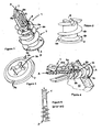
- anchor 1 comprises driving flange 2 with longitudinally extending anchoring element 3 having helical threads 4 thereon.
- the threads are interrupted by a separation which extends from the flange 2 (as shown in Figures 1, 2 and 4 ) to the forward drilling section 6.
- Forward drilling section 6 is comprised of separable arms 6a and 6b which are held together by frangible tie bar 7.
- the arms 6a and 6b extend through the threaded section 4a and constitute most of the length of the anchoring element 3.
- Sinusoidal (or similar shape-deviating across the central longitudinal axis) through-slot 8 defines the separable arms 6a and 6b.
- Initial thread section 4a, adjacent the flange 2 is of wider dimension and offset pitch as compared to the other threads.
- the frangible tie bar 7 is placed and pressed against the wall 10 and the anchor is rotated clockwise, (typically with a screwdriver or screw-gun or drill), with tie bar 7 providing a drill member designed to pierce a gypsum wall.
- front flange 2 is apertured with a key slot 2a adapted for engagement with a multitude of drivers (slot, Phillips, torque, etc.).
- the helical screw thread 4 engages the gypsum wall board and the anchor is threaded into the wall until barb shaped anti-reversal lugs 5a and 5b bite into the wall board as the flange 2 comes into flush contact with the wall board (see Figure 4 ).
- the lug engagement is a perceptible stop and signals the installer to stop tightening action of an installing tool at the point of detrimental overtightening.
- a screw 20 (used for supporting items with the anchor) is threaded through aperture 3a (shown in dotted lines) along the central longitudinal axis A of the anchor, with the thread thereof 20a cutting into the walls of aperture 3a.
- Screw 20 places outward pressure on tie bar 7, via expansion of supporting arms 6a and 6b, until the tie bar snaps with a perceptible pop. This indicates to the installer that supporting arms 6a and 6b have separated and are being forced into peripheral supporting engagement with the inner edges of the aperture formed by the anchor.
- the threads of the screw 20 engage and lock with cam elements 8a and 8b formed by the non-linear slot 8, to maintain the supporting arms in fixed engaging position shown in Figure 4 .
- Anchor threads 4 are sized to extend beyond the inner surface of the wallboard of varying thicknesses whereby a flight (shown as flight 4b) of the anchor bites into the adjacent inner surface of the wallboard, peripheral to the aperture formed by the anchor. This decreases anchor slippage and increases holding strength.
- alternating groove sections or thinned areas 9 are formed in between flights of the threads 4 preferably with a residual thickness of at least 1/3 of the original.
Claims (9)
- Selbstbohrender Hohlwandanker (1) für ein Einsetzen in eine hohle Wand (10), wobei der Anker (1) einen länglichen Kunststoffkörper (3) mit zwei Enden auf einer mittleren Längsachse (A) und eine Längsbohrung (3a) aufweist, die für das verschraubbare Aufnehmen einer Schraube (20) darin ausgebildet ist, wobei der Anker (1) ein Kopfteil an einem ersten Ende des Kunststoffkörpers (3) und ein Bohrelement (6) mit einer Bohrspitze (7) am anderen Ende des Kunststoffkörpers (3) aufweist, wobei der Kunststoffkörper (3) einen axialen Flansch (2) aufweist, der konzentrisch relativ zum Kunststoffkörper (3) am ersten Ende benachbart dem Kopfteil positioniert ist; wobei das Kopfteil, benachbart dem Flansch (2), in Längsrichtung positionierte und sich radial nach außen erstreckende äußere Gewindegänge (4) aufweist, die für ein Einsetzen durch Schrauben in die hohle Wand (10) ausgebildet sind; wobei der Anker (1) außerdem Verankerungsmittel (6a, 6b) aufweist, die so ausgebildet sind, dass sie distal zur Wand (10) sind, wenn der Anker in die Wand (10) eingesetzt wird, wobei das Verankerungsmittel (6a, 6b) verbundene aber trennbare Elemente (6a, 6b) des Bohrelementes (6) aufweist, wobei die trennbaren Elemente (6a, 6b) miteinander an der Bohrspitze (7) und mindestens einem Abschnitt des mit Gewinde versehenen Kopfteils verbunden sind, wobei die trennbaren Elemente (6a, 6b) durch einen Schlitz (8) getrennt sind, der mindestens einen Gang der Gewindegänge (4) unterbricht, und wobei der Schlitz (8) nichtlinear ist, wobei sich mindestens zwei Kurvenelemente (8a, 8b) nach innen über die Längsachse erstrecken; und wobei eine mittlere Öffnung (2a) im Flansch (2) für einen Eingriff mit einem rotierenden Schraubendreher für das verschraubbare Treiben des Ankers (1) in die hohle Wand (10) ausgebildet ist, und wobei der Flansch (2) ein Mittel (2) für das Verhindern eines Überdrehens des Ankers in der hohlen Wand aufweist, und wobei der Anker (1) ein Mittel (4b) für das Verhindern des Herausschraubens des Ankers (1) aus der Wand (10) vor dem Entfernen der Schraube (20) aus dem Anker (1) aufweist; wobei das Einsetzen der Schraube (20) durch Schrauben bewirkt, dass sich die verbundenen trennbaren Elemente (6a, 6b) an der Bohrspitze (7) zu einem Verankerungsmittel trennen; dadurch gekennzeichnet, dass die Schraube (20) mit den Kurvenelementen (8a, 8b) in Eingriff kommt, um die getrennten trennbaren Elemente (6a, 6b) in einer Verankerungsposition zu verriegeln, wobei mindestens ein Gang (4) der Gewindegänge dadurch mit einer distalen Fläche der Wand (10) in Eingriff kommt.
- Selbstbohrender Hohlwandanker nach Anspruch 1, wobei der Anker (1) aus einem halbsteifen Material mit einer ausreichenden Steifigkeit besteht, um sich verschraubbar leicht in die Hohlwandmaterialien zu schneiden, während er ebenfalls in der Lage ist, ein festes Halten auf der distalen Seite des Hohlwandmaterials zu bewirken, indem er ausreichend elastisch ist, um eine Halteposition einzunehmen, und um ihn ohne Aufspaltung oder Rissbildung zu halten.
- Selbstbohrender Hohlwandanker nach Anspruch 2, bei dem das halbsteife Material aus einem Material besteht, das unter glasfaserverstärkten Polyamiden und Polyestern ausgewählt wird, wobei die Glasfaserverstärkung von 10 bis 50 Vol.-% beträgt.
- Selbstbohrender Hohlwandanker nach Anspruch 2 oder 3, bei dem das halbsteife Material einen Grad der Abriebbarkeit aufweist, wobei das Verlaufen der Ankerspitze relativ zu einer Wand während der Anordnung der Ankerspitze an der Wand vor dem Einsetzen durch Schrauben minimiert wird.
- Selbstbohrender Hohlwandanker nach Anspruch 2, 3 oder 4, bei dem die trennbaren Verankerungselemente mit einem Zuganker verbunden sind, und wobei das halbsteife Material ausgebildet ist, um ein wahrnehmbares Knallen bei der richtigen Anordnung der Schraube bei einem Zerreißen des Zugankers und dem Positionieren der Verankerungselemente in der richtigen Verankerungsposition zu bewirken.
- Selbstbohrender Hohlwandanker nach einem der Ansprüche 2 bis 5, bei dem das Bohrelement (6) eine Schneidklinge aufweist.
- Selbstbohrender Hohlwandanker nach einem der Ansprüche 2 bis 6, bei dem mindestens zwei Abschnitte zwischen benachbarten Segmenten der äußeren Gewindegänge (4) dünner sind, wobei sich die Abschnitte auf entgegengesetzten Seiten des Schlitzes (8) befinden, und wobei die Abschnitte Gelenke aufweisen, die ausgebildet sind, um die Spannung auf das halbsteife Material der Verankerungselemente zu entlasten.
- Selbstbohrender Hohlwandanker nach einem der vorhergehenden Ansprüche, bei dem das Mittel für das Verhindern des Herausschraubens des Ankers (1) aus der Wand (10) vor dem Entfernen der Schraube (20) aus dem Anker (1) mindestens einen sich erstreckenden Ansatz (5a, 5b) auf einer Fläche des Flansches (2) aufweist, der ausgebildet ist, um die Wand zu kontaktieren, wobei der Ansatz (5a, 5b) von ausreichender Höhe ist, um mit der Wand (10) bei einem Kontakt des Flansches (2) mit der Wand (10) verankernd in Eingriff zu kommen, um dadurch die Drehung des Ankers (1) in beiden Richtungen zu verzögern.
- Selbstbohrender Hohlwandanker nach einem der vorhergehenden Ansprüche, bei dem das Mittel für das Verhindern des Herausschraubens des Ankers aus der Wand (10) vor dem Entfernen der Schraube (20) aus dem Anker (1) einen ersten Gang der Gewindegänge (4), benachbart dem Flansch (2) angeordnet, mit einem größeren Durchmesser relativ zu den anderen Gewindegängen aufweist und von unterschiedlicher Ganghöhe ist, wodurch das Schrauben des Ankers (1) in die Wand (10) nicht dadurch behindert wird, aber wobei das Herausschrauben des Ankers aus der Wand (10) behindert wird.
Priority Applications (1)
| Application Number | Priority Date | Filing Date | Title |
|---|---|---|---|
| PL05825810T PL1817504T3 (pl) | 2004-12-02 | 2005-11-29 | Kołek samowiercący do ścian szkieletowych |
Applications Claiming Priority (2)
| Application Number | Priority Date | Filing Date | Title |
|---|---|---|---|
| US11/001,945 US7144212B2 (en) | 2004-12-02 | 2004-12-02 | Self-drilling hollow wall anchor |
| PCT/US2005/043943 WO2006060776A1 (en) | 2004-12-02 | 2005-11-29 | Self-drilling hollow wall anchor |
Publications (3)
| Publication Number | Publication Date |
|---|---|
| EP1817504A1 EP1817504A1 (de) | 2007-08-15 |
| EP1817504A4 EP1817504A4 (de) | 2009-08-05 |
| EP1817504B1 true EP1817504B1 (de) | 2015-03-18 |
Family
ID=36565381
Family Applications (1)
| Application Number | Title | Priority Date | Filing Date |
|---|---|---|---|
| EP05825810.4A Active EP1817504B1 (de) | 2004-12-02 | 2005-11-29 | Selbstdrehender hohlwandanker |
Country Status (18)
| Country | Link |
|---|---|
| US (2) | US7144212B2 (de) |
| EP (1) | EP1817504B1 (de) |
| JP (1) | JP4806684B2 (de) |
| CN (1) | CN101065585B (de) |
| AR (1) | AR051783A1 (de) |
| AU (1) | AU2005311624B2 (de) |
| BR (1) | BRPI0518806A8 (de) |
| CA (1) | CA2585161C (de) |
| DK (1) | DK1817504T3 (de) |
| ES (1) | ES2539395T3 (de) |
| HK (1) | HK1109188A1 (de) |
| IL (1) | IL182646A0 (de) |
| MX (1) | MX2007005505A (de) |
| NZ (1) | NZ554807A (de) |
| PL (1) | PL1817504T3 (de) |
| RU (1) | RU2007124553A (de) |
| TW (1) | TWI331190B (de) |
| WO (1) | WO2006060776A1 (de) |
Families Citing this family (42)
| Publication number | Priority date | Publication date | Assignee | Title |
|---|---|---|---|---|
| CA2420722A1 (en) | 2003-03-04 | 2004-09-04 | Cobra Fixations Cie Ltee - Cobra Anchors Co. Ltd. | Wall mounted hook |
| US7762751B2 (en) * | 2004-02-05 | 2010-07-27 | Illinois Tool Works Inc. | Anchor |
| DE102004020852B4 (de) * | 2004-04-28 | 2006-07-13 | Hilti Ag | Eingussdübel |
| DE102004049489B3 (de) * | 2004-10-11 | 2006-03-30 | Hilti Ag | Ankerelement |
| CA2502008A1 (en) | 2005-03-21 | 2006-09-21 | Cobra Fixations Cie Ltee - Cobra Anchors Co. Ltd. | Anchor with toggle for hollow walls |
| CA2502044A1 (en) | 2005-03-21 | 2006-09-21 | Cobra Fixations Cie Ltee. - Cobra Anchors Co. Ltd. | Anchor assembly for fastener |
| US20080221624A1 (en) * | 2005-10-17 | 2008-09-11 | Gooch Hubert L | Systems and Methods for the Medical Treatment of Structural Tissue |
| US20080221623A1 (en) * | 2005-10-17 | 2008-09-11 | Gooch Hubert L | Systems and Methods for the Medical Treatment of Structural Tissue |
| US7748984B2 (en) * | 2006-02-10 | 2010-07-06 | Mcallister Craig M | Apparatus and method for instruction in orthopedic surgery |
| CN2910138Y (zh) * | 2006-05-18 | 2007-06-13 | 雷伟 | 万向型膨胀式椎弓根螺钉 |
| FR2915542B1 (fr) | 2007-04-27 | 2009-08-07 | Prospection Et D Inv S Techniq | Cheville d'ancrage fendue pour materiau friable |
| US8545153B2 (en) * | 2008-01-30 | 2013-10-01 | Delphi Technologies, Inc. | Free spin fastener assembly |
| DE102008010606A1 (de) * | 2008-02-22 | 2009-08-27 | Fischerwerke Gmbh & Co. Kg | Befestigungselement für Holzfaserdämmplatten |
| GB2462818A (en) * | 2008-08-18 | 2010-02-24 | Senico Ltd | Apparatus and method for fixing to a laminated material |
| CA2643664A1 (en) | 2008-10-30 | 2010-04-30 | Cobra Fixations Cie Ltee - Cobra Anchors Co. Ltd. | Wall-mounted hook |
| CA133911S (en) * | 2010-01-27 | 2011-02-03 | Cobra Fixations Cie Ltée Cobra Anchors Co Ltd | Wall anchor |
| CA2714848A1 (en) | 2010-09-16 | 2012-03-16 | Walther, Uli | Deck-to-building lateral-load connector |
| CA2736291A1 (en) | 2011-04-04 | 2012-10-04 | Walther, Uli | Toggle link deck to building connector |
| US9322733B2 (en) | 2011-07-25 | 2016-04-26 | Honeywell International Inc. | Duct port for pressure sensing |
| US9080587B1 (en) * | 2012-10-05 | 2015-07-14 | Michael C. Smith | Spike for securing a flexible member to earth strata |
| CN103223572B (zh) * | 2013-04-11 | 2015-06-17 | 漳州鑫一达五金电子有限公司 | 一种锚钉加工方法 |
| US9133630B2 (en) * | 2013-06-14 | 2015-09-15 | Dean Dougherty | Fastener anchor repair system and method |
| CN104564962B (zh) * | 2013-10-28 | 2017-01-18 | 徐福川 | 自钻式拉爆扣件及其成型方法 |
| US10539171B2 (en) | 2015-01-26 | 2020-01-21 | Good Earth Lighting, Inc. | Anchor fastener |
| US9869336B2 (en) * | 2015-01-26 | 2018-01-16 | Good Earth Lighting, Inc. | Anchor fastener |
| US10279146B2 (en) * | 2015-06-02 | 2019-05-07 | Eca Medical Instruments | Cannulated disposable torque limiting device with plastic shaft |
| CN106015234A (zh) * | 2016-08-11 | 2016-10-12 | 华文进 | 一种用于水泥墙体的膨胀螺钉 |
| CA2989037A1 (en) | 2016-12-22 | 2018-06-22 | The Hillman Group, Inc. | Hollow wall anchor |
| USD848251S1 (en) * | 2016-12-28 | 2019-05-14 | Masterpiece Hardware Industrial Co. Ltd | Screw anchor |
| USD860770S1 (en) * | 2017-09-15 | 2019-09-24 | Fischerwerke Gmbh & Co. Kg | Anchor |
| CN107830035A (zh) * | 2017-12-12 | 2018-03-23 | 樊金鑫 | 膨胀固栓 |
| ES2876196T3 (es) * | 2018-05-31 | 2021-11-12 | Locinox | Conjunto de fijación |
| US10697490B2 (en) * | 2018-07-24 | 2020-06-30 | Ojjo, Inc. | Threaded truss foundations and related systems, methods, and machines |
| US10748455B2 (en) * | 2018-08-29 | 2020-08-18 | Channell Commercial Corporation | Single side fastening system for identification placard for utility vault lids |
| US11619252B2 (en) | 2018-12-01 | 2023-04-04 | The Hillman Group, Inc. | Wallboard anchor |
| TWI705198B (zh) * | 2019-07-12 | 2020-09-21 | 金全益股份有限公司 | 壁虎釘結構 |
| US11174885B2 (en) * | 2019-08-08 | 2021-11-16 | Masterpiece Hardware Industrial Co., Ltd. | Expansion screw structure |
| CN111022463B (zh) * | 2019-12-05 | 2021-09-24 | 嘉兴市奥科五金科技有限公司 | 一种嵌入固定式的膨胀螺栓 |
| GB2590410B (en) * | 2019-12-16 | 2022-03-23 | Three Smith Group Ltd | Anchor assembly |
| CN111779748B (zh) * | 2020-07-18 | 2022-05-03 | 佛山市南海众勤五金电器有限公司 | 一种加固型免打孔膨胀螺丝 |
| EP4341567A1 (de) * | 2021-05-18 | 2024-03-27 | Crow, Gregory, Matthew | Hohlwandbefestigungselement |
| CN117693636A (zh) * | 2021-06-14 | 2024-03-12 | 眼镜蛇紧固件股份有限公司 | 具有可变形的扩展部分的墙壁锚定件 |
Citations (1)
| Publication number | Priority date | Publication date | Assignee | Title |
|---|---|---|---|---|
| US5692864A (en) * | 1995-12-21 | 1997-12-02 | K & R Industries, Inc. | Self-threading anchor with spreadable leg portions joined by a frangible drill end portion |
Family Cites Families (38)
| Publication number | Priority date | Publication date | Assignee | Title |
|---|---|---|---|---|
| US1248008A (en) * | 1917-01-20 | 1917-11-27 | Henry B Newhall | Bolt-anchor. |
| US2419555A (en) * | 1940-04-19 | 1947-04-29 | Charles D Fator | Self-threading and locking screw |
| US2601803A (en) * | 1948-11-04 | 1952-07-01 | Falcon Fasteners Inc | Fastening means |
| US4322194A (en) | 1979-09-12 | 1982-03-30 | Coats & Clark, Inc. | Wall anchor with self-drilling capability |
| JPS5888217A (ja) * | 1981-11-17 | 1983-05-26 | 松下電工株式会社 | エキスパンシヨンボルト用ナツト筒 |
| JPS59194810A (ja) * | 1983-04-20 | 1984-11-05 | Sekisui Chem Co Ltd | 複合ボルトの製造方法 |
| US4601625A (en) * | 1984-05-11 | 1986-07-22 | Illinois Tool Works Inc. | Self drilling threaded insert for drywall |
| US4708552A (en) * | 1984-09-12 | 1987-11-24 | Clairson International | Expansible mounting assembly |
| US5234299A (en) | 1987-08-03 | 1993-08-10 | Giannuzzi Louis | Self-drilling anchor |
| US5267423A (en) | 1987-08-03 | 1993-12-07 | Giannuzzi Louis | Self-drilling anchor and bearing plate assembly |
| US5039262A (en) | 1988-07-05 | 1991-08-13 | Giannuzzi Louis | Self-drilling wall anchor |
| JPH02151404A (ja) * | 1988-12-05 | 1990-06-11 | Shinjiyou Seisakusho:Kk | 拡開アンカーの下穴内奥を拡径する削成装置 |
| GB8908366D0 (en) * | 1989-04-13 | 1989-06-01 | Ist Lab Ltd | Improvements in or relating to automotive electrical systems |
| JPH0349632A (ja) * | 1989-07-18 | 1991-03-04 | Hironobu Yoshida | 浮きと重り兼用の固定具 |
| US5190425A (en) | 1991-10-21 | 1993-03-02 | Illinois Tool Works Inc. | Anchor |
| DE4140512C1 (de) * | 1991-12-09 | 1993-04-08 | A. Raymond & Cie, Grenoble, Fr | |
| US5308203A (en) | 1992-09-22 | 1994-05-03 | Titan Technologies, Inc. | Saw tipped anchor insert |
| US5536121A (en) | 1992-09-22 | 1996-07-16 | Titan Technologies, Inc. | Anchor insert |
| JP3009696U (ja) * | 1994-09-12 | 1995-04-11 | 国際鋲螺株式会社 | アンカー |
| US5626245A (en) | 1995-01-27 | 1997-05-06 | Schulte Corporation | Anchor for securing wire shelving, shelving system, and fastener for same |
| JPH08240211A (ja) * | 1995-03-07 | 1996-09-17 | Nifco Inc | スクリューグロメット |
| JP3835575B2 (ja) * | 1997-03-31 | 2006-10-18 | 株式会社パイオラックス | 連結具 |
| JP3930960B2 (ja) | 1998-01-26 | 2007-06-13 | 若井産業株式会社 | ねじ付きアンカー |
| FR2776034B1 (fr) | 1998-03-16 | 2000-04-14 | Spit Soc Prospect Inv Techn | Cheville d'ancrage pour materiau friable |
| US6164884A (en) | 1998-08-17 | 2000-12-26 | Mayr; Alfred Friedrich | Anchor with spreading elements |
| US6186716B1 (en) | 1998-11-12 | 2001-02-13 | Westerlund Products Corporation | Anchor bolt |
| US6139236A (en) | 1999-07-29 | 2000-10-31 | Koyo Kizai Co., Ltd. | Board anchor |
| DE19859220A1 (de) * | 1998-12-21 | 2000-06-29 | Fischer Artur Werke Gmbh | Spreizdübel |
| JP3290413B2 (ja) * | 1998-12-21 | 2002-06-10 | 光洋器材株式会社 | ボード用アンカー |
| JP2000310210A (ja) * | 1999-04-26 | 2000-11-07 | Kokusai Byora Kk | スクリューアンカー |
| CA2302038A1 (en) * | 1999-05-03 | 2000-11-03 | Illinois Tool Works Inc. | Wallboard anchor with hook |
| JP2000234613A (ja) * | 1999-11-26 | 2000-08-29 | Takeshi Yamada | 建築用締め付けボルト |
| US6382892B1 (en) | 2001-01-16 | 2002-05-07 | Dave C. Hempfling | Wall anchor with improved drilling tip |
| JP2002242920A (ja) * | 2001-02-13 | 2002-08-28 | Matsuda Kinzoku Kogyo Kk | 土台緊締用ナット |
| US6494653B2 (en) | 2001-04-17 | 2002-12-17 | Emerson Electric Company | Wall anchor |
| JP2004011678A (ja) * | 2002-06-04 | 2004-01-15 | Asahi Kasei Corp | 軽量気泡コンクリートパネルの固定ボルト |
| US20050084360A1 (en) * | 2003-10-10 | 2005-04-21 | Panasik Cheryl L. | Self-drilling anchor |
| US7001124B2 (en) * | 2004-02-05 | 2006-02-21 | Illinois Tool Works Inc. | Anchor |
-
2004
- 2004-12-02 US US11/001,945 patent/US7144212B2/en active Active
-
2005
- 2005-11-28 TW TW094141690A patent/TWI331190B/zh active
- 2005-11-29 AU AU2005311624A patent/AU2005311624B2/en not_active Ceased
- 2005-11-29 BR BRPI0518806A patent/BRPI0518806A8/pt not_active Application Discontinuation
- 2005-11-29 CN CN2005800406781A patent/CN101065585B/zh not_active Expired - Fee Related
- 2005-11-29 PL PL05825810T patent/PL1817504T3/pl unknown
- 2005-11-29 ES ES05825810.4T patent/ES2539395T3/es active Active
- 2005-11-29 WO PCT/US2005/043943 patent/WO2006060776A1/en active Application Filing
- 2005-11-29 RU RU2007124553/11A patent/RU2007124553A/ru unknown
- 2005-11-29 EP EP05825810.4A patent/EP1817504B1/de active Active
- 2005-11-29 MX MX2007005505A patent/MX2007005505A/es active IP Right Grant
- 2005-11-29 NZ NZ554807A patent/NZ554807A/en unknown
- 2005-11-29 JP JP2007544597A patent/JP4806684B2/ja active Active
- 2005-11-29 CA CA2585161A patent/CA2585161C/en active Active
- 2005-11-29 DK DK05825810.4T patent/DK1817504T3/da active
- 2005-12-01 AR ARP050105035A patent/AR051783A1/es unknown
-
2006
- 2006-01-12 US US11/330,609 patent/US7320569B2/en active Active
-
2007
- 2007-04-18 IL IL182646A patent/IL182646A0/en unknown
- 2007-12-28 HK HK07114223.3A patent/HK1109188A1/xx not_active IP Right Cessation
Patent Citations (1)
| Publication number | Priority date | Publication date | Assignee | Title |
|---|---|---|---|---|
| US5692864A (en) * | 1995-12-21 | 1997-12-02 | K & R Industries, Inc. | Self-threading anchor with spreadable leg portions joined by a frangible drill end portion |
Also Published As
| Publication number | Publication date |
|---|---|
| WO2006060776A9 (en) | 2006-09-28 |
| AU2005311624A1 (en) | 2006-06-08 |
| CN101065585B (zh) | 2011-06-15 |
| AR051783A1 (es) | 2007-02-07 |
| HK1109188A1 (en) | 2008-05-30 |
| US7144212B2 (en) | 2006-12-05 |
| US20060120821A1 (en) | 2006-06-08 |
| IL182646A0 (en) | 2007-07-24 |
| RU2007124553A (ru) | 2009-01-10 |
| AU2005311624B2 (en) | 2009-11-26 |
| DK1817504T3 (da) | 2015-06-22 |
| BRPI0518806A2 (pt) | 2008-12-09 |
| US7320569B2 (en) | 2008-01-22 |
| TWI331190B (en) | 2010-10-01 |
| EP1817504A1 (de) | 2007-08-15 |
| CA2585161A1 (en) | 2006-06-08 |
| JP2008523323A (ja) | 2008-07-03 |
| EP1817504A4 (de) | 2009-08-05 |
| CN101065585A (zh) | 2007-10-31 |
| NZ554807A (en) | 2010-09-30 |
| MX2007005505A (es) | 2007-07-09 |
| TW200624683A (en) | 2006-07-16 |
| US20060120822A1 (en) | 2006-06-08 |
| CA2585161C (en) | 2011-02-08 |
| WO2006060776A1 (en) | 2006-06-08 |
| BRPI0518806A8 (pt) | 2017-10-03 |
| ES2539395T3 (es) | 2015-06-30 |
| JP4806684B2 (ja) | 2011-11-02 |
| PL1817504T3 (pl) | 2015-08-31 |
Similar Documents
| Publication | Publication Date | Title |
|---|---|---|
| EP1817504B1 (de) | Selbstdrehender hohlwandanker | |
| US6186716B1 (en) | Anchor bolt | |
| US4861206A (en) | Straddling plug | |
| US5692864A (en) | Self-threading anchor with spreadable leg portions joined by a frangible drill end portion | |
| JP2520778B2 (ja) | 自己穿設型アンカ― | |
| EP0539139B1 (de) | Anker | |
| US4601625A (en) | Self drilling threaded insert for drywall | |
| US7261505B2 (en) | Self-drilling anchor | |
| EP2808567B1 (de) | Ankeranordnung mit Kippglied für Hohlwände | |
| JP2011080605A (ja) | セルフドリルアンカー | |
| US10837480B2 (en) | Hollow wall anchor | |
| SK284423B6 (sk) | Skrutka na pripevnenie kovových a/alebo plastových profilov alebo dosák na podklad | |
| JPH09112515A (ja) | ビス固定補助具 | |
| US5688090A (en) | Screw assembly | |
| KR20040018545A (ko) | 확장가능한 고정 플러그 | |
| EP0684395A2 (de) | Dübel mit Vorsprüngen gegen Verdrehung | |
| JP2855059B2 (ja) | コンクリートなどへのビス固定補助具 | |
| EP0679814A2 (de) | Gerillte Spreizdübel | |
| JP2002039135A (ja) | 軽量気泡コンクリート用ねじ | |
| WO2006031508A1 (en) | Self-drilling anchor |
Legal Events
| Date | Code | Title | Description |
|---|---|---|---|
| PUAI | Public reference made under article 153(3) epc to a published international application that has entered the european phase |
Free format text: ORIGINAL CODE: 0009012 |
|
| 17P | Request for examination filed |
Effective date: 20070419 |
|
| AK | Designated contracting states |
Kind code of ref document: A1 Designated state(s): AT BE BG CH CY CZ DE DK EE ES FI FR GB GR HU IE IS IT LI LT LU LV MC NL PL PT RO SE SI SK TR |
|
| DAX | Request for extension of the european patent (deleted) | ||
| A4 | Supplementary search report drawn up and despatched |
Effective date: 20090702 |
|
| RIC1 | Information provided on ipc code assigned before grant |
Ipc: F16B 13/06 20060101ALI20090626BHEP Ipc: F16B 13/00 20060101ALI20090626BHEP Ipc: F16B 13/04 20060101AFI20060619BHEP |
|
| 17Q | First examination report despatched |
Effective date: 20091019 |
|
| GRAP | Despatch of communication of intention to grant a patent |
Free format text: ORIGINAL CODE: EPIDOSNIGR1 |
|
| INTG | Intention to grant announced |
Effective date: 20140926 |
|
| GRAS | Grant fee paid |
Free format text: ORIGINAL CODE: EPIDOSNIGR3 |
|
| GRAA | (expected) grant |
Free format text: ORIGINAL CODE: 0009210 |
|
| AK | Designated contracting states |
Kind code of ref document: B1 Designated state(s): AT BE BG CH CY CZ DE DK EE ES FI FR GB GR HU IE IS IT LI LT LU LV MC NL PL PT RO SE SI SK TR |
|
| REG | Reference to a national code |
Ref country code: GB Ref legal event code: FG4D |
|
| REG | Reference to a national code |
Ref country code: CH Ref legal event code: EP |
|
| REG | Reference to a national code |
Ref country code: IE Ref legal event code: FG4D |
|
| REG | Reference to a national code |
Ref country code: AT Ref legal event code: REF Ref document number: 716775 Country of ref document: AT Kind code of ref document: T Effective date: 20150415 |
|
| REG | Reference to a national code |
Ref country code: DE Ref legal event code: R096 Ref document number: 602005046102 Country of ref document: DE Effective date: 20150430 |
|
| REG | Reference to a national code |
Ref country code: CH Ref legal event code: NV Representative=s name: MARKS AND CLERK (LUXEMBOURG) LLP, CH |
|
| REG | Reference to a national code |
Ref country code: DK Ref legal event code: T3 Effective date: 20150619 |
|
| REG | Reference to a national code |
Ref country code: ES Ref legal event code: FG2A Ref document number: 2539395 Country of ref document: ES Kind code of ref document: T3 Effective date: 20150630 |
|
| REG | Reference to a national code |
Ref country code: NL Ref legal event code: T3 |
|
| REG | Reference to a national code |
Ref country code: SE Ref legal event code: TRGR |
|
| PG25 | Lapsed in a contracting state [announced via postgrant information from national office to epo] |
Ref country code: LT Free format text: LAPSE BECAUSE OF FAILURE TO SUBMIT A TRANSLATION OF THE DESCRIPTION OR TO PAY THE FEE WITHIN THE PRESCRIBED TIME-LIMIT Effective date: 20150318 |
|
| REG | Reference to a national code |
Ref country code: LT Ref legal event code: MG4D |
|
| PG25 | Lapsed in a contracting state [announced via postgrant information from national office to epo] |
Ref country code: GR Free format text: LAPSE BECAUSE OF FAILURE TO SUBMIT A TRANSLATION OF THE DESCRIPTION OR TO PAY THE FEE WITHIN THE PRESCRIBED TIME-LIMIT Effective date: 20150619 Ref country code: LV Free format text: LAPSE BECAUSE OF FAILURE TO SUBMIT A TRANSLATION OF THE DESCRIPTION OR TO PAY THE FEE WITHIN THE PRESCRIBED TIME-LIMIT Effective date: 20150318 |
|
| REG | Reference to a national code |
Ref country code: PL Ref legal event code: T3 |
|
| PG25 | Lapsed in a contracting state [announced via postgrant information from national office to epo] |
Ref country code: RO Free format text: LAPSE BECAUSE OF FAILURE TO SUBMIT A TRANSLATION OF THE DESCRIPTION OR TO PAY THE FEE WITHIN THE PRESCRIBED TIME-LIMIT Effective date: 20150318 Ref country code: PT Free format text: LAPSE BECAUSE OF FAILURE TO SUBMIT A TRANSLATION OF THE DESCRIPTION OR TO PAY THE FEE WITHIN THE PRESCRIBED TIME-LIMIT Effective date: 20150720 Ref country code: SK Free format text: LAPSE BECAUSE OF FAILURE TO SUBMIT A TRANSLATION OF THE DESCRIPTION OR TO PAY THE FEE WITHIN THE PRESCRIBED TIME-LIMIT Effective date: 20150318 Ref country code: CZ Free format text: LAPSE BECAUSE OF FAILURE TO SUBMIT A TRANSLATION OF THE DESCRIPTION OR TO PAY THE FEE WITHIN THE PRESCRIBED TIME-LIMIT Effective date: 20150318 Ref country code: EE Free format text: LAPSE BECAUSE OF FAILURE TO SUBMIT A TRANSLATION OF THE DESCRIPTION OR TO PAY THE FEE WITHIN THE PRESCRIBED TIME-LIMIT Effective date: 20150318 |
|
| REG | Reference to a national code |
Ref country code: FR Ref legal event code: PLFP Year of fee payment: 11 |
|
| PG25 | Lapsed in a contracting state [announced via postgrant information from national office to epo] |
Ref country code: IS Free format text: LAPSE BECAUSE OF FAILURE TO SUBMIT A TRANSLATION OF THE DESCRIPTION OR TO PAY THE FEE WITHIN THE PRESCRIBED TIME-LIMIT Effective date: 20150718 |
|
| REG | Reference to a national code |
Ref country code: DE Ref legal event code: R097 Ref document number: 602005046102 Country of ref document: DE |
|
| PLBE | No opposition filed within time limit |
Free format text: ORIGINAL CODE: 0009261 |
|
| STAA | Information on the status of an ep patent application or granted ep patent |
Free format text: STATUS: NO OPPOSITION FILED WITHIN TIME LIMIT |
|
| 26N | No opposition filed |
Effective date: 20151221 |
|
| PG25 | Lapsed in a contracting state [announced via postgrant information from national office to epo] |
Ref country code: SI Free format text: LAPSE BECAUSE OF FAILURE TO SUBMIT A TRANSLATION OF THE DESCRIPTION OR TO PAY THE FEE WITHIN THE PRESCRIBED TIME-LIMIT Effective date: 20150318 |
|
| PG25 | Lapsed in a contracting state [announced via postgrant information from national office to epo] |
Ref country code: MC Free format text: LAPSE BECAUSE OF FAILURE TO SUBMIT A TRANSLATION OF THE DESCRIPTION OR TO PAY THE FEE WITHIN THE PRESCRIBED TIME-LIMIT Effective date: 20150318 |
|
| REG | Reference to a national code |
Ref country code: FR Ref legal event code: PLFP Year of fee payment: 12 |
|
| REG | Reference to a national code |
Ref country code: AT Ref legal event code: UEP Ref document number: 716775 Country of ref document: AT Kind code of ref document: T Effective date: 20150318 |
|
| PG25 | Lapsed in a contracting state [announced via postgrant information from national office to epo] |
Ref country code: BG Free format text: LAPSE BECAUSE OF FAILURE TO SUBMIT A TRANSLATION OF THE DESCRIPTION OR TO PAY THE FEE WITHIN THE PRESCRIBED TIME-LIMIT Effective date: 20150318 Ref country code: HU Free format text: LAPSE BECAUSE OF FAILURE TO SUBMIT A TRANSLATION OF THE DESCRIPTION OR TO PAY THE FEE WITHIN THE PRESCRIBED TIME-LIMIT; INVALID AB INITIO Effective date: 20051129 |
|
| PG25 | Lapsed in a contracting state [announced via postgrant information from national office to epo] |
Ref country code: CY Free format text: LAPSE BECAUSE OF FAILURE TO SUBMIT A TRANSLATION OF THE DESCRIPTION OR TO PAY THE FEE WITHIN THE PRESCRIBED TIME-LIMIT Effective date: 20150318 |
|
| PG25 | Lapsed in a contracting state [announced via postgrant information from national office to epo] |
Ref country code: TR Free format text: LAPSE BECAUSE OF FAILURE TO SUBMIT A TRANSLATION OF THE DESCRIPTION OR TO PAY THE FEE WITHIN THE PRESCRIBED TIME-LIMIT Effective date: 20150318 |
|
| REG | Reference to a national code |
Ref country code: FR Ref legal event code: PLFP Year of fee payment: 13 |
|
| PGFP | Annual fee paid to national office [announced via postgrant information from national office to epo] |
Ref country code: IT Payment date: 20191128 Year of fee payment: 15 |
|
| PGFP | Annual fee paid to national office [announced via postgrant information from national office to epo] |
Ref country code: CH Payment date: 20201201 Year of fee payment: 16 |
|
| PGFP | Annual fee paid to national office [announced via postgrant information from national office to epo] |
Ref country code: ES Payment date: 20210329 Year of fee payment: 16 |
|
| PG25 | Lapsed in a contracting state [announced via postgrant information from national office to epo] |
Ref country code: IT Free format text: LAPSE BECAUSE OF NON-PAYMENT OF DUE FEES Effective date: 20201129 |
|
| PGFP | Annual fee paid to national office [announced via postgrant information from national office to epo] |
Ref country code: IE Payment date: 20211123 Year of fee payment: 17 |
|
| REG | Reference to a national code |
Ref country code: CH Ref legal event code: PL |
|
| REG | Reference to a national code |
Ref country code: ES Ref legal event code: FD2A Effective date: 20230215 |
|
| PG25 | Lapsed in a contracting state [announced via postgrant information from national office to epo] |
Ref country code: ES Free format text: LAPSE BECAUSE OF NON-PAYMENT OF DUE FEES Effective date: 20211130 |
|
| PGFP | Annual fee paid to national office [announced via postgrant information from national office to epo] |
Ref country code: LU Payment date: 20230526 Year of fee payment: 18 |
|
| PG25 | Lapsed in a contracting state [announced via postgrant information from national office to epo] |
Ref country code: LI Free format text: LAPSE BECAUSE OF NON-PAYMENT OF DUE FEES Effective date: 20220630 Ref country code: CH Free format text: LAPSE BECAUSE OF NON-PAYMENT OF DUE FEES Effective date: 20220630 |
|
| PGFP | Annual fee paid to national office [announced via postgrant information from national office to epo] |
Ref country code: PL Payment date: 20230523 Year of fee payment: 18 Ref country code: AT Payment date: 20230526 Year of fee payment: 18 |
|
| PGFP | Annual fee paid to national office [announced via postgrant information from national office to epo] |
Ref country code: BE Payment date: 20230525 Year of fee payment: 18 |
|
| PG25 | Lapsed in a contracting state [announced via postgrant information from national office to epo] |
Ref country code: IE Free format text: LAPSE BECAUSE OF NON-PAYMENT OF DUE FEES Effective date: 20221129 |
|
| PGFP | Annual fee paid to national office [announced via postgrant information from national office to epo] |
Ref country code: NL Payment date: 20231127 Year of fee payment: 19 |
|
| PGFP | Annual fee paid to national office [announced via postgrant information from national office to epo] |
Ref country code: GB Payment date: 20231127 Year of fee payment: 19 |
|
| PGFP | Annual fee paid to national office [announced via postgrant information from national office to epo] |
Ref country code: SE Payment date: 20231127 Year of fee payment: 19 Ref country code: FR Payment date: 20231127 Year of fee payment: 19 Ref country code: FI Payment date: 20231127 Year of fee payment: 19 Ref country code: DK Payment date: 20231127 Year of fee payment: 19 Ref country code: DE Payment date: 20231127 Year of fee payment: 19 |
|
| PGFP | Annual fee paid to national office [announced via postgrant information from national office to epo] |
Ref country code: BE Payment date: 20231127 Year of fee payment: 19 |