EP1814802B1 - Mehrkomponenten-kartusche - Google Patents
Mehrkomponenten-kartusche Download PDFInfo
- Publication number
- EP1814802B1 EP1814802B1 EP05806516A EP05806516A EP1814802B1 EP 1814802 B1 EP1814802 B1 EP 1814802B1 EP 05806516 A EP05806516 A EP 05806516A EP 05806516 A EP05806516 A EP 05806516A EP 1814802 B1 EP1814802 B1 EP 1814802B1
- Authority
- EP
- European Patent Office
- Prior art keywords
- cartridge
- container
- wall surface
- filling space
- component
- Prior art date
- Legal status (The legal status is an assumption and is not a legal conclusion. Google has not performed a legal analysis and makes no representation as to the accuracy of the status listed.)
- Active
Links
- 238000002347 injection Methods 0.000 claims abstract description 28
- 239000007924 injection Substances 0.000 claims abstract description 28
- 230000009969 flowable effect Effects 0.000 claims abstract description 7
- 238000005520 cutting process Methods 0.000 claims description 6
- 238000003860 storage Methods 0.000 claims description 5
- 238000007599 discharging Methods 0.000 claims 1
- 239000000203 mixture Substances 0.000 claims 1
- 150000001875 compounds Chemical class 0.000 abstract 1
- 230000002093 peripheral effect Effects 0.000 abstract 1
- 238000003825 pressing Methods 0.000 description 9
- 238000000034 method Methods 0.000 description 7
- 230000003068 static effect Effects 0.000 description 6
- 238000002156 mixing Methods 0.000 description 5
- 238000001125 extrusion Methods 0.000 description 4
- 235000011837 pasties Nutrition 0.000 description 4
- 238000000071 blow moulding Methods 0.000 description 3
- 238000010276 construction Methods 0.000 description 3
- 238000004026 adhesive bonding Methods 0.000 description 2
- 238000004519 manufacturing process Methods 0.000 description 2
- 239000000463 material Substances 0.000 description 2
- 238000005192 partition Methods 0.000 description 2
- 238000003466 welding Methods 0.000 description 2
- 230000006978 adaptation Effects 0.000 description 1
- 239000000853 adhesive Substances 0.000 description 1
- 230000001070 adhesive effect Effects 0.000 description 1
- 230000000295 complement effect Effects 0.000 description 1
- 230000001419 dependent effect Effects 0.000 description 1
- 238000006073 displacement reaction Methods 0.000 description 1
- 238000005429 filling process Methods 0.000 description 1
- 239000004570 mortar (masonry) Substances 0.000 description 1
- 238000002360 preparation method Methods 0.000 description 1
- 230000002787 reinforcement Effects 0.000 description 1
- 229920003002 synthetic resin Polymers 0.000 description 1
- 239000000057 synthetic resin Substances 0.000 description 1
Images

Classifications
-
- B—PERFORMING OPERATIONS; TRANSPORTING
- B65—CONVEYING; PACKING; STORING; HANDLING THIN OR FILAMENTARY MATERIAL
- B65D—CONTAINERS FOR STORAGE OR TRANSPORT OF ARTICLES OR MATERIALS, e.g. BAGS, BARRELS, BOTTLES, BOXES, CANS, CARTONS, CRATES, DRUMS, JARS, TANKS, HOPPERS, FORWARDING CONTAINERS; ACCESSORIES, CLOSURES, OR FITTINGS THEREFOR; PACKAGING ELEMENTS; PACKAGES
- B65D81/00—Containers, packaging elements, or packages, for contents presenting particular transport or storage problems, or adapted to be used for non-packaging purposes after removal of contents
- B65D81/32—Containers, packaging elements, or packages, for contents presenting particular transport or storage problems, or adapted to be used for non-packaging purposes after removal of contents for packaging two or more different materials which must be maintained separate prior to use in admixture
- B65D81/3233—Flexible containers disposed within rigid containers
-
- B—PERFORMING OPERATIONS; TRANSPORTING
- B65—CONVEYING; PACKING; STORING; HANDLING THIN OR FILAMENTARY MATERIAL
- B65D—CONTAINERS FOR STORAGE OR TRANSPORT OF ARTICLES OR MATERIALS, e.g. BAGS, BARRELS, BOTTLES, BOXES, CANS, CARTONS, CRATES, DRUMS, JARS, TANKS, HOPPERS, FORWARDING CONTAINERS; ACCESSORIES, CLOSURES, OR FITTINGS THEREFOR; PACKAGING ELEMENTS; PACKAGES
- B65D81/00—Containers, packaging elements, or packages, for contents presenting particular transport or storage problems, or adapted to be used for non-packaging purposes after removal of contents
- B65D81/32—Containers, packaging elements, or packages, for contents presenting particular transport or storage problems, or adapted to be used for non-packaging purposes after removal of contents for packaging two or more different materials which must be maintained separate prior to use in admixture
- B65D81/325—Containers having parallel or coaxial compartments, provided with a piston or a movable bottom for discharging contents
-
- B—PERFORMING OPERATIONS; TRANSPORTING
- B05—SPRAYING OR ATOMISING IN GENERAL; APPLYING FLUENT MATERIALS TO SURFACES, IN GENERAL
- B05C—APPARATUS FOR APPLYING FLUENT MATERIALS TO SURFACES, IN GENERAL
- B05C17/00—Hand tools or apparatus using hand held tools, for applying liquids or other fluent materials to, for spreading applied liquids or other fluent materials on, or for partially removing applied liquids or other fluent materials from, surfaces
- B05C17/005—Hand tools or apparatus using hand held tools, for applying liquids or other fluent materials to, for spreading applied liquids or other fluent materials on, or for partially removing applied liquids or other fluent materials from, surfaces for discharging material from a reservoir or container located in or on the hand tool through an outlet orifice by pressure without using surface contacting members like pads or brushes
- B05C17/00553—Hand tools or apparatus using hand held tools, for applying liquids or other fluent materials to, for spreading applied liquids or other fluent materials on, or for partially removing applied liquids or other fluent materials from, surfaces for discharging material from a reservoir or container located in or on the hand tool through an outlet orifice by pressure without using surface contacting members like pads or brushes with means allowing the stock of material to consist of at least two different components
-
- B—PERFORMING OPERATIONS; TRANSPORTING
- B05—SPRAYING OR ATOMISING IN GENERAL; APPLYING FLUENT MATERIALS TO SURFACES, IN GENERAL
- B05C—APPARATUS FOR APPLYING FLUENT MATERIALS TO SURFACES, IN GENERAL
- B05C17/00—Hand tools or apparatus using hand held tools, for applying liquids or other fluent materials to, for spreading applied liquids or other fluent materials on, or for partially removing applied liquids or other fluent materials from, surfaces
- B05C17/005—Hand tools or apparatus using hand held tools, for applying liquids or other fluent materials to, for spreading applied liquids or other fluent materials on, or for partially removing applied liquids or other fluent materials from, surfaces for discharging material from a reservoir or container located in or on the hand tool through an outlet orifice by pressure without using surface contacting members like pads or brushes
- B05C17/00583—Hand tools or apparatus using hand held tools, for applying liquids or other fluent materials to, for spreading applied liquids or other fluent materials on, or for partially removing applied liquids or other fluent materials from, surfaces for discharging material from a reservoir or container located in or on the hand tool through an outlet orifice by pressure without using surface contacting members like pads or brushes the container for the material to be dispensed being deformable
-
- B—PERFORMING OPERATIONS; TRANSPORTING
- B05—SPRAYING OR ATOMISING IN GENERAL; APPLYING FLUENT MATERIALS TO SURFACES, IN GENERAL
- B05C—APPARATUS FOR APPLYING FLUENT MATERIALS TO SURFACES, IN GENERAL
- B05C17/00—Hand tools or apparatus using hand held tools, for applying liquids or other fluent materials to, for spreading applied liquids or other fluent materials on, or for partially removing applied liquids or other fluent materials from, surfaces
- B05C17/005—Hand tools or apparatus using hand held tools, for applying liquids or other fluent materials to, for spreading applied liquids or other fluent materials on, or for partially removing applied liquids or other fluent materials from, surfaces for discharging material from a reservoir or container located in or on the hand tool through an outlet orifice by pressure without using surface contacting members like pads or brushes
- B05C17/00596—The liquid or other fluent material being supplied from a rigid removable cartridge having no active dispensing means, i.e. the cartridge requiring cooperation with means of the handtool to expel the material
Definitions
- the invention relates to a cartridge for separate storage and for co-extrusion of at least two components of a flowable mass with an outlet nozzle and an injection piston according to the features of the preamble of claim 1.
- Under flowable mass is in particular a pasty material with pasty components, such as multi-component Adhesives, multi-component synthetic resins or multi-component mortar.
- cartridges which have a filling chamber divided into two chambers, in which the two components are introduced and stored separately from one another.
- the components located in the chambers can be ejected together in a predetermined mixing ratio through outlet nozzles.
- the ejected components are mixed together in a static mixer arranged downstream of the outlet nozzles.
- the outlet nozzles of such cartridges are usually arranged on a common outlet nozzle whose foot region has an external thread for receiving and fixing attachment elements, such as a closure cap or a static mixer.
- a two-component cartridge according to the preamble of claim 1 which has the form and construction of a one-component cartridge.
- Located in the cartridge are two containers for holding the components of the flowable mass.
- the containers fill the interior of the cartridge, but are not connected to the inner lateral surface of the cartridge.
- the US 5 647 510 also shows a two-component cartridge in the form and construction of a one-component cartridge.
- the interior takes on two containers, which may differ in cross-section and volume, but together the interior completely fill the cartridge.
- the two containers stabilize each other during the pressing process. They are not connected to the inner surface of the cartridge.
- a two-component cartridge which has the form and construction of a one-component cartridge and thus can be used in conventional cartridge presses.
- the filling space of the cartridge is divided by a longitudinally arranged, flexible partition into two chambers.
- the flexible partition is separated during the injection process by the injection piston from the cartridge wall and received in a cavity of the injection piston.
- DE 102 07 763 A1 discloses a two-component cartridge having two tubular containers which extend over circular sectors and complement each other to a full circle, so that the cartridge has a cylindrical shape.
- the containers can be inserted into a cylinder of an extrusion gun and compressed by a punch of the extrusion gun in the longitudinal direction.
- a two-component cartridge is known, which is composed of five parts. It consists of two containers for holding the components, a piece of pipe for receiving the compressible containers, a head piece with outlet nozzle and an injection piston for pressing out the components.
- the containers are formed as blow molding and are glued to the head. After mounting the cartridge, the filling takes place through the inlet openings of the blow-molded parts.
- the manufacturing process of such a multi-component cartridge is very cost-intensive due to the high number of half-parts, their complex assembly process and the time-consuming filling process.
- the invention is therefore based on the object to propose a multi-component cartridge for separate storage and common extrusion of two or more components of a flowable material in a predetermined mixing ratio, which can be inexpensively manufactured, used as a disposable cartridge and pressed with a conventional one-component cartridge press.
- the multi-component cartridge according to the invention serves for the separate storage and for the common pressing of at least two components of a flowable mass.
- the cartridge has an outer tube closed at one end by a header.
- the headpiece has an outlet nozzle.
- An outer jacket of the outlet nozzle has fastening means for receiving and fixing attachment elements. Attachment elements, such as a cap or a static mixer, are connected via corresponding Fixing means fixed to the outlet nozzle.
- a filling space inside the outer tube is closed by an injection piston.
- the injection piston is displaceable in the direction of the head piece and presses the mass through the outlet nozzle into the static mixer.
- In the filling space of the cartridge at least one, over the entire length of the space extending, longitudinally compressible container is arranged.
- the container divides the filling space of the cartridge into separate chambers, one component being stored in each chamber.
- the chambers have approximately constant cross-sectional areas along their length in terms of shape and size, the cross-sectional areas complementing the cross-sectional area of the cartridge.
- the area ratio of the chamber cross sections determines the mixing ratio of the components during pressing and is approximately constant over the entire pressing process.
- the container is fixed to an inner circumferential surface of the outer tube over its entire length. When the components are pressed out, the container is compressed by the injection piston and its fixation on the inner jacket of the outer tube is successively released by the injection piston.
- the outer tube is made in one piece as a molded part to which the head piece is formed.
- the filling space of the cartridge body is divided only by the introduction of the container into separate chambers.
- the containers of the cartridge are designed as blow-molded parts. The design as blow-molded parts causes the containers have only one opening, namely an outlet nozzle. Since the containers are otherwise closed, leaks in the area of chamber walls can not occur.
- the container is fixed to the inner circumferential surface of the outer tube over its entire length.
- the fixation is advantageously carried out linearly in the longitudinal direction of the container.
- the connection can be continuous or segmented. If the connection is segmented, then the connection points can be designed as points or webs, wherein the webs can be arranged parallel or transverse to the longitudinal direction of the container.
- the fixation of the container can be done form-, force and / or cohesive.
- the fixation can be done with an empty or filled container.
- a further development of the invention provides that the inner circumferential surface of the outer tube has a spring extending in the longitudinal direction, which engages positively and / or non-positively in a groove of the outer lateral surface of the container.
- the container can be inserted in the longitudinal direction in the spring of the cartridge or pressed perpendicular to the longitudinal direction. It is also possible to provide the groove on the cartridge body and the spring on the container.
- the container in the filling chamber of the cartridge is arranged eccentrically and rests with a part of its outer surface on the inner lateral surface of the cartridge.
- the container has preformed kinks.
- the container of the cartridge is axially accordion compressible with little effort and is folded together after pressing the components through the injection piston at the kinks.
- the preparation of the container as blow molding allows thin-walled longitudinal walls and a thick-walled outlet nozzle.
- the injection piston has a convex profile on its face facing the filling space, with which it rests on the corresponding end face of the container.
- the container is folded at the nearest kink and pressed against the inner circumferential surface of the outer tube.
- the convex profile may be in the form of a spherical cap, but other outwardly directed geometries, such as an arrangement of mutually inclined, planar surfaces are possible.
- the injection piston has a cutting edge on the face facing the filling space.
- the cutting edge is located on the Inner lateral surface of the cartridge.
- an outlet nozzle is arranged on the end face of the container pointing in the direction of the head piece. It is arranged coaxially in the mouth of the cartridge and is aligned with the end of the mouth of the outlet nozzle of the cartridge.
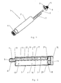
- inventive multi-component cartridge 1 is used for separate storage and common pressing of two components of a pasty mass and has a cylindrical outer tube 2, a head piece 3 and a cylindrical injection piston 4.
- an outlet nozzle 5 is formed, which has a fastening means 6 for the adaptation of various attachment elements, not shown.
- the fastening means 6 is designed as external thread 8.
- attachment elements for example, a closure cap or a static mixer can be fixed to the external thread 8 of the head piece 3.
- a container 7 is arranged, which is produced as a blow molding and having an outlet nozzle 9.
- FIG. 2 shows a longitudinal section through the mounted cartridge 1 of FIG. 1
- the outer tube 2 and the head piece 3 can be made as a one-piece cartridge body 10, in the illustrated and described embodiment of the invention, the disk-shaped and stiffened ribs head piece 3 is welded or glued to the outer tube 2.
- the container 7 is arranged in a filling space 11 in the interior of the outer tube 2 and fixed to an inner circumferential surface 12 of the cartridge body 10.
- the outlet nozzle 9 penetrates the outlet nozzle 5 of the cartridge body 10 axially and terminates flush with the end face thereof.
- the injection piston 4 closes the filling chamber 11 and seals it against the escape of a pasty mass, not shown.
- the container 7 divides the filling space 11 of the cartridge body 10 into two separate chambers 13 and 14.
- the chamber 14 is formed by the interior of the container 7 and the chamber 13 through the remaining space of the filling space 11.
- the filling of the chamber 14 with a first component of the mass, not shown, takes place through the outlet nozzle 9 of the container 7, the filling of the chamber 13 with a likewise not shown second component of the mass through a pipe end 15 of the cartridge body 10 before the pipe end 15 with the injection piston 4 is closed.
- the container 7 extends over the entire length of the filling space 11 and is made thin-walled. It has an approximately constant cross-section over its entire length and can be folded accordion-like in the longitudinal direction.
- the outer circumferential surface 16 of the container 7 preformed kinks 17, 17 'on.
- the container 7 is folded when moving the injection piston 4 in the direction of the head piece 3 defined.
- the injection piston 4 has a cutting edge 18 on its end face facing the filling space 11.
- the cutting edge 18 is circumferentially disposed on the outer circumference of the injection piston 4 and is located on the inner circumferential surface 12 of the cartridge body 10th at.
- the cutting edge 18 seals the chamber 13 and separates the axial displacement of the injection piston 4 a fixation 19 between the cartridge body 10 and the container 7 from.
- the filling space 11 facing end face of the injection piston 4 has a convex profile 20 in the form of a spherical cap.
- the profile 20 is inclined in the direction of the outer circumferential surface of the cartridge body 10 and abuts against a bottom 21 of the container 7.
- FIG. 3 shows a cross section through the cartridge 1.
- the container 7 is arranged eccentrically in the filling chamber 11 of the cartridge body 10 and abuts with a contact surface 24 of its outer shell 16 on the inner shell 12 of the cartridge body 10.
- the chamber 14 of the container 7 has the shape of a circular sector in cross section.
- the contact surface 24 of the container 7 has a corresponding groove 22, in which the spring 23 of the cartridge body 10 engages positively and non-positively.
- the groove 22 is provided with undercuts and the spring 23 with reinforcements engaging therein. It is also possible to provide the spring 23 on the container 7 and the groove 22 on the cartridge body 10 (not shown).
- FIG. 4 shows a plan view of the outlet nozzle side of the cartridge 1.
- the outlet nozzle 5 is arranged on the head piece 3 eccentrically to the outer tube 2.
- the outlet nozzle 9 of the container 7 is concentrically fixed.
- the fastening means 6 forming external thread 8 is formed on which an unillustrated static mixer is adaptable.
Landscapes
- Engineering & Computer Science (AREA)
- Mechanical Engineering (AREA)
- Containers And Packaging Bodies Having A Special Means To Remove Contents (AREA)
- Package Specialized In Special Use (AREA)
- Coating Apparatus (AREA)
- Separation By Low-Temperature Treatments (AREA)
- Dental Tools And Instruments Or Auxiliary Dental Instruments (AREA)
Description
- Die Erfindung betrifft eine Kartusche zum getrennten Aufbewahren und zum gemeinsamen Auspressen von mindestens zwei Komponenten einer fließfähigen Masse mit einer Austrittsdüse und einem Spritzkolben gemäß den Merkmalen des Oberbegriffs des Anspruchs 1. Unter fließfähiger Masse soll dabei insbesondere ein pastöses Material mit pastösen Komponenten, wie beispielsweise Mehrkomponenten-Klebstoffe, Mehrkomponenten-Kunstharze oder Mehrkomponenten-Mörtel verstanden werden.
- Zum Aufbewahren und Ausbringen von Zweikomponenten-Massen werden Kartuschen verwendet, die einen in zwei Kammern aufgeteilten Füllraum besitzen, in denen die zwei Komponenten voneinander getrennt eingebracht und aufbewahrt sind. Mittels einem oder zweier Spritzkolben lassen sich die in den Kammern befindlichen Komponenten gemeinsam in einem vorgegebenen Mischungsverhältnis durch Austrittsdüsen ausspritzen. Die ausgespritzten Komponenten werden in einem nach den Austrittsdüsen angeordneten Statikmischer miteinander vermischt. Die Austrittsdüsen solcher Kartuschen sind üblicherweise an einer gemeinsamen Austrittsdüse angeordnet, deren Fußbereich ein Außengewinde zur Aufnahme und zum Festsetzen von Aufsatzelementen, wie zum Beispiel einer Verschlusskappe oder eines Statikmischers, aufweist.
- Aus der
US 6 454 129 B1 ist eine Zweikomponenten-Kartusche gemäß dem Oberbegriff des Anspruchs 1 bekannt, die Form und Aufbau einer Einkomponenten-Kartusche aufweist. Inliegend in der Kartusche befinden sich zwei Behältnisse zur Aufnahme der Komponenten der fließfähigen Masse. Die Behältnisse füllen den Innenraum der Kartusche aus, sind aber mit der Innenmantelfläche der Kartusche nicht verbunden. - Die
US 5 647 510 zeigt ebenfalls eine Zweikomponenten-Kartusche in Form und Aufbau einer Einkomponenten-Kartusche. Der Innenraum nimmt zwei Behältnisse auf, die sich im Querschnitt und Volumen unterscheiden können, gemeinsam aber den Innenraum der Kartusche voll ausfüllen. Die beiden Behältnisse stabilisieren sich beim Auspressvorgang gegenseitig. Sie sind nicht mit der Innenmantelfläche der Kartusche verbunden. - Aus der
DE 39 13 409 A1 ist eine Zweikomponenten-Kartusche bekannt, welche die Form und den Aufbau einer Einkomponenten-Kartusche aufweist und somit in herkömmlichen Kartuschenpressen verwendet werden kann. Der Füllraum der Kartusche wird durch eine in Längsrichtung angeordnete, flexible Trennwand in zwei Kammern unterteilt. Die flexible Trennwand wird beim Spritzvorgang durch den Spritzkolben von der Kartuschenwand abgetrennt und in einem Hohlraum des Spritzkolbens aufgenommen. - In der
DE 102 07 763 A1 ist eine Zweikomponenten-Kartusche offenbart, die zwei schlauchförmige Behältnisse aufweist, die sich über Kreissektoren erstrecken und sich zu einem Vollkreis ergänzen, so dass die Kartusche eine Zylinderform aufweist. Zum Auspressen der Komponenten sind die Behältnisse in einen Zylinder einer Auspresspistole einsetzbar und durch einen Stempel der Auspresspistole in Längsrichtung zusammendrückbar. - Aus der
DE 103 10 162 A1 ist eine Zweikomponenten-Kartusche bekannt, die fünfteilig aufgebaut ist. Sie besteht aus zwei Behältnissen zur Aufnahme der Komponenten, einem Rohrstück zur Aufnahme der zusammendrückbaren Behältnisse, einem Kopfstück mit Austrittsdüse und einem Spritzkolben zum Auspressen der Komponenten. Die Behältnisse sind als Blasformteil ausgebildet und werden mit dem Kopfstück verklebt. Nach der Montage der Kartusche erfolgt die Befüllung durch die Eintrittsöffnungen der Blasformteile. Der Herstellungsprozess einer derartigen Mehrkomponenten-Kartusche ist aufgrund der hohen Anzahl von Halbteilen, deren aufwendigen Montageprozess und dem zeitaufwendigen Füllprozess sehr kostenintensiv. - Der Erfindung liegt daher die Aufgabe zugrunde, eine Mehrkomponenten-Kartusche zum getrennten Aufbewahren und gemeinsamen Auspressen von zwei oder mehr Komponenten eines fließfähigen Materials in einem vorgegebenen Mischungsverhältnis vorzuschlagen, die preisgünstig herstellbar, als Einwegkartusche verwendbar und mit einer herkömmlichen Einkomponenten-Kartuschenpresse auspressbar ist.
- Diese Aufgabe wird erfindungsgemäß durch eine Mehrkomponenten-Kartusche mit den Merkmalen des Anspruchs 1 gelöst. Weitere vorteilhafte Ausgestaltungen sind den Unteransprüchen zu entnehmen.
- Die erfindungsgemäße Mehrkomponenten-Kartusche dient zum getrennten Aufbewahren und zum gemeinsamen Auspressen von mindestens zwei Komponenten einer fließfähigen Masse. Die Kartusche weist ein Außenrohr auf, das an einem Ende durch ein Kopfstück geschlossen ist. Das Kopfstück weist eine Austrittsdüse auf. Ein Außenmantel der Austrittsdüse weist Befestigungsmittel zur Aufnahme und zum Festsetzen von Aufsatzelementen auf. Aufsatzelemente, wie zum Beispiel eine Verschlusskappe oder ein Statikmischer, werden über korrespondierende Befestigungsmittel an der Austrittsdüse fixiert. Ein Füllraum im Inneren des Außenrohrs wird durch einen Spritzkolben abgeschlossen. Der Spritzkolben ist in Richtung des Kopfstücks verschiebbar und presst die Masse durch die Austrittsdüse in den Statikmischer. Im Füllraum der Kartusche ist mindestens ein, sich über die gesamte Länge des Raums erstreckendes, in Längsrichtung zusammendrückbares Behältnis angeordnet. Das Behältnis teilt den Füllraum der Kartusche in voneinander getrennte Kammern, wobei in jeder Kammer eine Komponente aufbewahrt wird. Die Kammern weisen über ihre Länge nach Form und Größe in etwa konstante Querschnittsflächen auf, wobei sich die Querschnittsflächen zur Querschnittsfläche zur Kartusche ergänzen. Das Flächenverhältnis der Kammerquerschnitte bestimmt das Mischungsverhältnis der Komponenten beim Auspressen und ist über den gesamten Auspressvorgang annähernd konstant. Das Behältnis ist an einer Innenmantelfläche des Außenrohrs über seine gesamte Länge fixiert. Beim Auspressen der Komponenten wird das Behältnis durch den Spritzkolben zusammengedrückt und dessen Fixierung am Innenmantel des Außenrohrs sukzessive durch den Spritzkolben gelöst.
- Bei einer erfindungsgemäßen Kartusche ist das Außenrohr einstückig als Formteil hergestellt, an das das Kopfstück angeformt ist. Dies hat den Vorteil, dass die Anzahl der Halbteile für den Herstellungsprozess reduziert wird und eine druckdichte Verbindung zwischen dem Kopfstück und dem Außenrohr nicht beim Montageprozess hergestellt werden muss. Vorteilhafterweise wird der Füllraum des Kartuschenkörpers erst durch das Einbringen des Behältnisses in voneinander getrennte Kammern aufgeteilt. Dies hat den Vorteil, dass mit einem Kartuschenkörper durch Variation des Behältnisses beliebige Mischungsverhältnisse realisiert werden können. Zweckmäßigerweise sind die Behältnisse der Kartusche als Blasformteile ausgeführt. Die Ausführung als Blasformteile bewirkt, dass die Behältnisse nur eine Öffnung, nämlich eine Austrittsdüse aufweisen. Da die Behältnisse ansonsten geschlossen sind, können Undichtigkeiten im Bereich von Kammerwänden nicht auftreten.
- Bei einer Ausgestaltung der Erfindung ist das Behältnis an der Innenmantelfläche des Außenrohrs über seine gesamte Länge fixiert. Die Fixierung erfolgt dabei vorteilhafterweise linienförmig in Längsrichtung des Behältnisses. Die Verbindung kann durchgehend oder auch segmentiert sein. Ist die Verbindung segmentiert, so können die Verbindungsstellen als Punkte oder Stege ausgeführt sein, wobei die Stege parallel oder quer zur Längsrichtung des Behältnisses angeordnet sein können.
- Die Fixierung des Behältnisses kann dabei form-, kraft- und/oder stoffschlüssig erfolgen. Dazu können alle bekannten Techniken wie zum Beispiel Rasten, Kleben oder Schweißen eingesetzt werden. Abhängig von der eingesetzten Technik kann die Fixierung bei leerem oder auch gefülltem Behältnis erfolgen.
- Eine Weiterbildung der Erfindung sieht vor, dass die Innenmantelfläche des Außenrohrs eine in Längsrichtung verlaufende Feder aufweist, die in eine Nut der Außenmantelfläche des Behältnisses form- und/oder kraftschlüssig eingreift. Das Behältnis kann dabei in Längsrichtung in die Feder der Kartusche eingeschoben oder senkrecht zur Längsrichtung eingedrückt werden. Es ist auch möglich, die Nut am Kartuschenkörper und die Feder am Behältnis vorzusehen.
- In einer bevorzugten Ausgestaltung der Erfindung ist das Behältnis im Füllraum der Kartusche exzentrisch angeordnet und liegt mit einem Teil seiner Außenfläche an der Innenmantelfläche der Kartusche an. So ist es möglich, die Mantelflächen einfach durch Kleben oder Schweißen miteinander zu verbinden.
- Erfindungsgemäß weist das Behältnis vorgeformte Knickstellen auf. Dadurch ist das Behältnis der Kartusche mit geringem Kraftaufwand axial ziehharmonikaartig zusammendrückbar und wird nach dem Auspressen der Komponenten durch den Spritzkolben an den Knickstellen zusammengefaltet. Die Herstellung des Behältnisses als Blasformteil ermöglicht dünnwandige Längswände und eine dickwandige Austrittsdüse.
- Vorteilhafterweise weist der Spritzkolben auf seiner zum Füllraum weisenden Stirnfläche ein konvexes Profil auf, mit dem er auf der korrespondierenden Stirnfläche des Behältnisses anliegt. Beim Verschieben des Spritzkolbens wird das Behältnis an der nächstliegenden Knickstelle gefaltet und an die Innenmantelfläche des Außenrohrs angedrückt. Das konvexe Profil kann in Form einer Kugelkalotte ausgeführt sein, wobei jedoch auch andere nach außen gerichtete Geometrien, wie zum Beispiel eine Anordnung von zueinander geneigten, planen Flächen möglich sind.
- Der Spritzkolben weist bei einer Ausgestaltung der Erfindung auf der zum Füllraum weisenden Stirnfläche eine Schneidkante auf. Die Schneidkante liegt an der Innenmantelfläche der Kartusche an. Beim Auspressen der Komponente wird sukzessive der entleerte Teil des Behältnisses von der Innenmantelfläche der Kartusche gelöst und das abgescherte Teilstück an den Knickstellen gefaltet. Dies stellt sicher, dass sich der wirksame Querschnitt des Behältnis beim Auspressen nicht verändert und somit das Mischungsverhältnis der ausgepressten Komponenten zumindest in etwa konstant bleibt.
- In einer weiteren vorteilhaften Ausgestaltung ist an der in Richtung Kopfstück weisenden Stirnfläche des Behältnisses eine Austrittsdüse angeordnet. Sie ist in der Mündungsöffnung der Kartusche koaxial angeordnet und fluchtet mit dem Ende der Mündungsöffnung der Austrittsdüse der Kartusche. Dies hat den Vorteil, dass die Komponenten nach dem Austritt aus den Mündungsöffnungen sehr leicht vermischbar sind.
- Die Erfindung wird nachfolgend an Hand eines in den Zeichnungen dargestellten Ausführungsbeispiels näher erläutert.
- Es zeigen:
- Figur 1
- eine Ausführungsform einer erfindungsgemäßen Kartusche in perspektivischer Explosionsdarstellung;
- Figur 2
- einen Längsschnitt durch die montierte Kartusche aus
Figur 1 ; - Figur 3
- ein Querschnitt durch die montierte Kartusche aus
Figur 1 ; und - Figur 4
- eine Stirnansicht einer Austrittsdüsenseite der montierten Kartusche gemäß
Figur 1 . - Die in
Figur 1 dargestellte, erfindungsgemäße Mehrkomponenten-Kartusche 1 dient zum getrennten Aufbewahren und zum gemeinsamen Auspressen von zwei Komponenten einer pastösen Masse und weist ein zylindrisches Außenrohr 2, ein Kopfstück 3 und einen zylindrischen Spritzkolben 4 auf. Am Kopfstück 3 ist eine Austrittsdüse 5 angeformt, die ein Befestigungsmittel 6 zur Adaption von verschiedenen, nicht dargestellten Aufsatzelementen aufweist. Im dargestellten und beschriebenen Ausführungsbeispiel der Erfindung ist das Befestigungsmittel 6 als Außengewinde 8 ausgeführt. Als Aufsatzelemente können zum Beispiel eine Verschlusskappe oder ein Statikmischer an dem Außengewinde 8 des Kopfstückes 3 fixiert werden. Im Außenrohr 2 ist ein Behältnis 7 angeordnet, das als Blasformteil hergestellt ist und eine Austrittsdüse 9 aufweist. -
Figur 2 zeigt einen Längsschnitt durch die montierte Kartusche 1 vonFigur 1 . Das Außenrohr 2 und das Kopfstück 3 können als einstückiger Kartuschenkörper 10 hergestellt sein, im dargestellten und beschriebenen Ausführungsbeispiel der Erfindung ist das scheibenförmige und mit Rippen versteifte Kopfstück 3 mit dem Außenrohr 2 verschweißt oder verklebt. Das Behältnis 7 ist in einem Füllraum 11 im Innern des Außenrohrs 2 angeordnet und an einer Innenmantelfläche 12 des Kartuschenkörpers 10 fixiert. Die Austrittsdüse 9 durchdringt die Austrittsdüse 5 des Kartuschenkörpers 10 axial und schließt fluchtend mit deren Stirnfläche ab. Der Spritzkolben 4 verschließt den Füllraum 11 und dichtet ihn gegen das Austreten einer nicht dargestellten pastösen Masse ab. - Das Behältnis 7 unterteilt den Füllraum 11 des Kartuschenkörpers 10 in zwei voneinander getrennte Kammern 13 und 14. Die Kammer 14 wird durch den Innenraum des Behältnisses 7 und die Kammer 13 durch den verbleibenden Raum des Füllraums 11 gebildet. Die Füllung der Kammer 14 mit einer nicht dargestellten ersten Komponente der Masse erfolgt durch die Austrittsdüse 9 des Behältnisses 7, die Füllung der Kammer 13 mit einer ebenfalls nicht dargestellten zweiten Komponente der Masse erfolgt durch ein Rohrende 15 des Kartuschenkörpers 10, bevor das Rohrende 15 mit dem Spritzkolben 4 verschlossen wird. Das Behältnis 7 erstreckt sich über die gesamte Länge des Füllraums 11 und ist dünnwandig ausgeführt. Es weist über seine gesamte Länge einen annähernd konstanten Querschnitt auf und ist in Längsrichtung ziehharmonikaartig zusammenfaltbar. Um das Behältnis 7 beim Auspressen der nicht dargestellten Komponenten in einer bestimmten Form zusammenzudrücken, weist die Außenmantelfläche 16 des Behältnisses 7 vorgeformte Knickstellen 17, 17' auf. Entlang den Knickstellen 17, 17' wird das Behältnis 7 beim Verschieben des Spritzkolbens 4 in Richtung des Kopfstücks 3 definiert zusammengefaltet.
- Der Spritzkolben 4 weist an seiner zum Füllraum 11 weisenden Stirnfläche eine Schneidkante 18 auf. Die Schneidkante 18 ist am äußeren Umfang des Spritzkolbens 4 umlaufend angeordnet und liegt an der Innenmantelfläche 12 des Kartuschenkörpers 10 an. Die Schneidkante 18 dichtet die Kammer 13 ab und trennt beim axialen Verschieben des Spritzkolbens 4 eine Fixierung 19 zwischen dem Kartuschenkörper 10 und dem Behältnis 7 ab. Die zum Füllraum 11 weisende Stirnfläche des Spritzkolbens 4 weist ein konvexes Profil 20 in Form einer Kugelkalotte auf. Das Profil 20 ist in Richtung der Außenmantelfläche des Kartuschenkörpers 10 geneigt und liegt an einem Boden 21 des Behältnisses 7 an. Beim Verschieben des Spritzkolbens 4 werden die nicht dargestellten Komponenten der Masse durch die Austrittsdüsen 5, 9 ausgepresst, wobei das Behältnis 7 entlang den Knickstellen 17, 17' sukzessive gefaltet und von der Innenmantelfläche 12 des Kartuschenkörpers 10 abgetrennt wird.
-
Figur 3 zeigt einen Querschnitt durch die Kartusche 1. Das Behältnis 7 ist im Füllraum 11 des Kartuschenkörpers 10 exzentrisch angeordnet und liegt mit einer Anlagefläche 24 seines Außenmantels 16 am Innenmantel 12 des Kartuschenkörpers 10 an. Die Kammer 14 des Behältnis 7 weist im Querschnitt die Form eines Kreissektors auf. An der Innenmantelfläche 12 des Kartuschenkörpers 10 ist im Bereich der Anlagefläche 24 des Behältnis 7 eine axial verlaufende Feder 23 angeordnet. Die Anlagefläche 24 des Behältnis 7 weist eine dazu korrespondierende Nut 22 auf, in welche die Feder 23 des Kartuschenkörpers 10 form- und kraftschlüssig eingreift. Zur Verstärkung des Kraftschlusses ist die Nut 22 mit Hinterschnitten und die Feder 23 mit darin eingreifenden Verstärkungen versehen. Es ist ebenso möglich, die Feder 23 am Behältnis 7 und die Nut 22 am Kartuschenkörper 10 vorzusehen (nicht dargestellt). -
Figur 4 zeigt eine Draufsicht auf die Austrittsdüsenseite der Kartusche 1. Die Austrittsdüse 5 ist am Kopfstück 3 exzentrisch zum Außenrohr 2 angeordnet. In der Austrittsdüse 5 ist die Austrittsdüse 9 des Behältnisses 7 konzentrisch fixiert. Am Außenmantel der Austrittsdüse 5 ist das das Befestigungsmittel 6 bildende Außengewinde 8 angeformt, an welchem ein nicht dargestellter Statikmischer adaptierbar ist.
Claims (9)
- Mehrkomponenten-Kartusche (1) zum getrennten Aufbewahren und zum gemeinsamen Auspressen von mindestens zwei Komponenten einer fließfähigen Masse, mit einer Austrittsdüse (5) und einem Auspresskolben (4), wobei in einem Innen- oder Füllraum (11) der Kartusche (1) mindestens ein sich über die Länge des Füllraumes (11) erstreckendes, einen Teil eines Querschnitts des Füllraums (11) einnehmendes, in Längsrichtung zusammendrückbares Behältnis (7) angeordnet ist, das den Füllraum (11) in voneinander getrennte Kammern (13, 14) zur Aufnahme der einzelnen Komponenten unterteilt, dadurch gekennzeichnet, dass das Behältnis (7) an einer Innenmantelfläche (12) der Kartusche (1) über seine Länge fixiert ist und die Fixierung (19) beim Auspressen der Komponenten sukzessive durch den Auspresskolben (4) gelöst wird.
- Mehrkomponenten-Kartusche nach Anspruch 1, dadurch gekennzeichnet, dass das Behältnis (7) über seine Außenmantelfläche (16) stoffschlüssig mit der Innenmantelfläche (12) der Kartusche (1) verbunden ist.
- Mehrkomponenten-Kartusche nach Anspruch 1, dadurch gekennzeichnet, dass das Behältnis (7) über seine Außenmantelfläche (16) form- und/oder kraftschlüssig mit der Innenmantelfläche (12) der Kartusche (1) verbunden ist und die Innenmantelfläche (12) der Kartusche (1) eine in Längsrichtung verlaufende Feder (23) oder Nut aufweist, die in eine Nut (22) oder Feder der Außenmantelfläche (16) des Behältnisses (7) eingreift.
- Mehrkomponenten-Kartusche nach Anspruch 1, dadurch gekennzeichnet, dass das Behältnis (7) im Füllraum (11) der Kartusche (1) exzentrisch angeordnet ist und mit seiner Außenmantelfläche (16) an der Innenmantelfläche (12) der Kartusche (1) anliegt.
- Mehrkomponenten-Kartusche nach Anspruch 1, dadurch gekennzeichnet, dass das Behältnis (7) an seiner Mantelfläche (16) eine Vielzahl von vorgeformten Knickstellen (17, 17') aufweist.
- Mehrkomponenten-Kartusche nach Anspruch 1, dadurch gekennzeichnet, dass der Spritzkolben (4) auf seiner zum Füllraum (11) weisenden Stirnfläche ein konvexes Profil (20) aufweist, mit dem er an einem Boden (21) des Behältnisses (7) anliegt.
- Mehrkomponenten-Kartusche nach Anspruch 1, dadurch gekennzeichnet, dass der Spritzkolben (4) auf der zum Füllraum (11) weisenden Stirnfläche eine Schneidkante (18) aufweist, die an der Innenmantelfläche (12) der Kartusche (1) anliegt.
- Mehrkomponenten-Kartusche nach Anspruch 1, dadurch gekennzeichnet, dass in der Austrittsdüse (5) der Kartusche (1) eine Austrittsdüse (9) des Behältnisses (7) koaxial angeordnet ist.
- Mehrkomponenten-Kartusche nach Anspruch 8, dadurch gekennzeichnet, dass die Enden der Austrittsdüse (9) des Behältnisses (7) und der Austrittsdüse (5) der Kartusche (1) miteinander fluchten.
Priority Applications (1)
| Application Number | Priority Date | Filing Date | Title |
|---|---|---|---|
| PL05806516T PL1814802T3 (pl) | 2004-11-25 | 2005-10-27 | Wieloskładnikowy ładunek |
Applications Claiming Priority (2)
| Application Number | Priority Date | Filing Date | Title |
|---|---|---|---|
| DE102004056908A DE102004056908A1 (de) | 2004-11-25 | 2004-11-25 | Mehrkomponenten-Kartusche |
| PCT/EP2005/011501 WO2006056287A1 (de) | 2004-11-25 | 2005-10-27 | Mehrkomponenten-kartusche |
Publications (2)
| Publication Number | Publication Date |
|---|---|
| EP1814802A1 EP1814802A1 (de) | 2007-08-08 |
| EP1814802B1 true EP1814802B1 (de) | 2008-05-28 |
Family
ID=35643891
Family Applications (1)
| Application Number | Title | Priority Date | Filing Date |
|---|---|---|---|
| EP05806516A Active EP1814802B1 (de) | 2004-11-25 | 2005-10-27 | Mehrkomponenten-kartusche |
Country Status (10)
| Country | Link |
|---|---|
| EP (1) | EP1814802B1 (de) |
| CN (1) | CN101065298B (de) |
| AT (1) | ATE396933T1 (de) |
| DE (2) | DE102004056908A1 (de) |
| DK (1) | DK1814802T3 (de) |
| ES (1) | ES2306244T3 (de) |
| MY (1) | MY142211A (de) |
| PL (1) | PL1814802T3 (de) |
| TW (1) | TW200616861A (de) |
| WO (1) | WO2006056287A1 (de) |
Families Citing this family (9)
| Publication number | Priority date | Publication date | Assignee | Title |
|---|---|---|---|---|
| DE102007051968A1 (de) | 2007-10-31 | 2009-05-07 | Fischerwerke Gmbh & Co. Kg | Mehrkomponenten-Kartusche |
| DE102008022999A1 (de) | 2008-05-09 | 2009-11-12 | Fischerwerke Gmbh & Co. Kg | Kolben für eine Kartusche und Kartusche |
| DE102008051944A1 (de) * | 2008-10-16 | 2010-04-22 | Schoeller Arca Systems Gmbh | Verpackungseinheit für untereinander reaktive Stoffe |
| DE102008064050A1 (de) * | 2008-12-19 | 2010-06-24 | Fischerwerke Gmbh & Co. Kg | Mehrkomponentenkartusche |
| DE102009016943A1 (de) * | 2009-04-08 | 2010-10-14 | Fischerwerke Gmbh & Co. Kg | Mehrkomponenten-Kartusche |
| WO2011131483A1 (de) * | 2010-04-19 | 2011-10-27 | Sulzer Mixpac Ag | Stehfähige kartusche, austragsvorrichtung für eine solche sowie verfahren zur verwendung der kartusche |
| DE102011010763B4 (de) * | 2011-02-10 | 2013-03-14 | Frank Wolff | Mehrkammer-Kartuschen-Vorrichtung |
| DE102014013679A1 (de) * | 2013-10-16 | 2015-04-16 | Fischerwerke Gmbh & Co. Kg | Mehrkomponentenkartusche |
| DE102014013680A1 (de) | 2013-10-16 | 2015-04-16 | Fischerwerke Gmbh & Co. Kg | Mehrkomponentenkartusche |
Family Cites Families (14)
| Publication number | Priority date | Publication date | Assignee | Title |
|---|---|---|---|---|
| DE1486622A1 (de) * | 1965-03-22 | 1969-07-17 | Spiess C F & Sohn | Zweikomponenten-Behaelter |
| US4340154A (en) * | 1980-10-24 | 1982-07-20 | Voplex Corporation | Caulker for dispensing two viscous components |
| US4493436A (en) * | 1983-03-16 | 1985-01-15 | Loctite Corporation | Compartmental cartridge |
| DE8335149U1 (de) * | 1983-12-08 | 1984-11-15 | Henkel KGaA, 4000 Düsseldorf | Verpackung fuer schuett- fliess- oder streichfaehiges Material |
| DE3913409A1 (de) * | 1989-04-24 | 1990-10-25 | Fischer Artur Werke Gmbh | Kartusche mit zwei kammern |
| JPH08502712A (ja) * | 1993-08-20 | 1996-03-26 | アー. ケラー,ヴィルヘルム | 折りたためるカートリッジを備えた多成分計量および相対比例配分装置 |
| US6170715B1 (en) * | 1996-06-20 | 2001-01-09 | Versa Pak Pty. Ltd. | Beverage dispenser |
| DE19635652C2 (de) * | 1996-09-03 | 1998-11-05 | Henkel Kgaa | Kartuschenbeutel |
| DE29720316U1 (de) * | 1997-11-17 | 1998-01-29 | Andris Raimund Gmbh & Co Kg | Zweikammer-Dosierspender |
| US6454129B1 (en) * | 1999-12-14 | 2002-09-24 | Ronald D. Green | Collapsible dispensing system |
| WO2003057581A1 (en) * | 2002-01-07 | 2003-07-17 | Choong-Hyun Jung | Container for discharging paste therefrom |
| DE10207763A1 (de) * | 2002-02-23 | 2003-09-04 | Fischer Artur Werke Gmbh | Mehrkomponenten-Kartusche |
| JP4168237B2 (ja) * | 2002-07-15 | 2008-10-22 | ニプロ株式会社 | 2成分混合型プレフィルドシリンジ |
| DE10310162A1 (de) * | 2003-03-08 | 2004-09-16 | Fischerwerke Artur Fischer Gmbh & Co. Kg | Kartusche zum Ausbringen von ein oder mehreren Komponenten einer Masse |
-
2004
- 2004-11-25 DE DE102004056908A patent/DE102004056908A1/de not_active Withdrawn
-
2005
- 2005-10-27 DK DK05806516T patent/DK1814802T3/da active
- 2005-10-27 EP EP05806516A patent/EP1814802B1/de active Active
- 2005-10-27 ES ES05806516T patent/ES2306244T3/es active Active
- 2005-10-27 PL PL05806516T patent/PL1814802T3/pl unknown
- 2005-10-27 DE DE502005004307T patent/DE502005004307D1/de active Active
- 2005-10-27 AT AT05806516T patent/ATE396933T1/de active
- 2005-10-27 WO PCT/EP2005/011501 patent/WO2006056287A1/de active IP Right Grant
- 2005-10-27 CN CN2005800404860A patent/CN101065298B/zh not_active Expired - Fee Related
- 2005-11-16 MY MYPI20055363A patent/MY142211A/en unknown
- 2005-11-21 TW TW094140781A patent/TW200616861A/zh unknown
Also Published As
| Publication number | Publication date |
|---|---|
| CN101065298B (zh) | 2010-12-22 |
| TW200616861A (en) | 2006-06-01 |
| MY142211A (en) | 2010-11-15 |
| WO2006056287A1 (de) | 2006-06-01 |
| CN101065298A (zh) | 2007-10-31 |
| DE102004056908A1 (de) | 2006-06-01 |
| PL1814802T3 (pl) | 2008-10-31 |
| DE502005004307D1 (de) | 2008-07-10 |
| DK1814802T3 (da) | 2008-09-08 |
| EP1814802A1 (de) | 2007-08-08 |
| ATE396933T1 (de) | 2008-06-15 |
| ES2306244T3 (es) | 2008-11-01 |
Similar Documents
| Publication | Publication Date | Title |
|---|---|---|
| EP1814802B1 (de) | Mehrkomponenten-kartusche | |
| EP1443868B1 (de) | Vorrichtung zum lagern, mischen und ausbringen einer fliessfähigen masse | |
| EP0645124B1 (de) | Spritze zum dosierten Abgeben von viskosen Werkstoffen, insbesondere von dentalen Werkstoffen | |
| EP2560888B1 (de) | Stehfähige kartusche, austragsvorrichtung für eine solche sowie verfahren zur verwendung der kartusche | |
| EP1871686A1 (de) | Mehrkomponenten-kartusche | |
| EP1676791B1 (de) | Mehrkammerkartusche für mehrkomponentige plastische Massen mit axial hintereinander angeordneten Kammern | |
| EP3405293B1 (de) | Foliengebinde sowie baugruppe aus einer auspressvorrichtung und einem foliengebinde | |
| DE10347938B4 (de) | Kopfteil für einen Mehrkammerschlauchbeutel | |
| EP3389876B1 (de) | Baugruppe aus einem foliengebinde und einer auspressvorrichtung sowie foliengebinde | |
| EP0942787B1 (de) | Vorrichtung zum lagern, auspressen und dosieren von zwei-komponenten-zusammensetzungen | |
| EP2163490B1 (de) | Kassette für mehrkomponentige Massen | |
| DE10207763A1 (de) | Mehrkomponenten-Kartusche | |
| DE102016122041A1 (de) | Mehrkomponentenbehältnis | |
| EP3741469B1 (de) | Mehrkammerkartusche und verfahren zu ihrer befüllung | |
| DE202004021209U1 (de) | Mehrkomponenten-Kartusche | |
| EP2199228B1 (de) | Mehrkomponentenkartusche | |
| DE102007051968A1 (de) | Mehrkomponenten-Kartusche | |
| DE3835093C2 (de) | Rohr zur Verwendung von Ausdrückpistolen | |
| DE102018117146A1 (de) | Mehrkammerkartusche | |
| DE102004057556A1 (de) | Mehrkomponentenkartusche | |
| EP1955779B1 (de) | Zweikammerkartusche | |
| EP3756771A1 (de) | Mehrkammerkartusche | |
| EP4365103A1 (de) | Mehrkammerkartusche | |
| EP4151554A1 (de) | Koaxialkartusche mit solldehnstellen zum rückstellkraftfreien auspressen einer fliessfähigen mehrkomponentenmasse | |
| DE4430713B4 (de) | Kartusche |
Legal Events
| Date | Code | Title | Description |
|---|---|---|---|
| PUAI | Public reference made under article 153(3) epc to a published international application that has entered the european phase |
Free format text: ORIGINAL CODE: 0009012 |
|
| 17P | Request for examination filed |
Effective date: 20070117 |
|
| AK | Designated contracting states |
Kind code of ref document: A1 Designated state(s): AT BE BG CH CY CZ DE DK EE ES FI FR GB GR HU IE IS IT LI LT LU LV MC NL PL PT RO SE SI SK TR |
|
| GRAP | Despatch of communication of intention to grant a patent |
Free format text: ORIGINAL CODE: EPIDOSNIGR1 |
|
| DAX | Request for extension of the european patent (deleted) | ||
| RAP1 | Party data changed (applicant data changed or rights of an application transferred) |
Owner name: FISCHERWERKE GMBH & CO. KG |
|
| GRAS | Grant fee paid |
Free format text: ORIGINAL CODE: EPIDOSNIGR3 |
|
| GRAA | (expected) grant |
Free format text: ORIGINAL CODE: 0009210 |
|
| AK | Designated contracting states |
Kind code of ref document: B1 Designated state(s): AT BE BG CH CY CZ DE DK EE ES FI FR GB GR HU IE IS IT LI LT LU LV MC NL PL PT RO SE SI SK TR |
|
| REG | Reference to a national code |
Ref country code: GB Ref legal event code: FG4D Free format text: NOT ENGLISH |
|
| REG | Reference to a national code |
Ref country code: CH Ref legal event code: EP |
|
| REF | Corresponds to: |
Ref document number: 502005004307 Country of ref document: DE Date of ref document: 20080710 Kind code of ref document: P |
|
| REG | Reference to a national code |
Ref country code: IE Ref legal event code: FG4D Free format text: LANGUAGE OF EP DOCUMENT: GERMAN |
|
| REG | Reference to a national code |
Ref country code: SE Ref legal event code: TRGR |
|
| PG25 | Lapsed in a contracting state [announced via postgrant information from national office to epo] |
Ref country code: SI Free format text: LAPSE BECAUSE OF FAILURE TO SUBMIT A TRANSLATION OF THE DESCRIPTION OR TO PAY THE FEE WITHIN THE PRESCRIBED TIME-LIMIT Effective date: 20080528 |
|
| PG25 | Lapsed in a contracting state [announced via postgrant information from national office to epo] |
Ref country code: FI Free format text: LAPSE BECAUSE OF FAILURE TO SUBMIT A TRANSLATION OF THE DESCRIPTION OR TO PAY THE FEE WITHIN THE PRESCRIBED TIME-LIMIT Effective date: 20080528 |
|
| REG | Reference to a national code |
Ref country code: PL Ref legal event code: T3 |
|
| REG | Reference to a national code |
Ref country code: ES Ref legal event code: FG2A Ref document number: 2306244 Country of ref document: ES Kind code of ref document: T3 |
|
| PG25 | Lapsed in a contracting state [announced via postgrant information from national office to epo] |
Ref country code: LV Free format text: LAPSE BECAUSE OF FAILURE TO SUBMIT A TRANSLATION OF THE DESCRIPTION OR TO PAY THE FEE WITHIN THE PRESCRIBED TIME-LIMIT Effective date: 20080528 |
|
| PG25 | Lapsed in a contracting state [announced via postgrant information from national office to epo] |
Ref country code: IS Free format text: LAPSE BECAUSE OF FAILURE TO SUBMIT A TRANSLATION OF THE DESCRIPTION OR TO PAY THE FEE WITHIN THE PRESCRIBED TIME-LIMIT Effective date: 20080928 |
|
| REG | Reference to a national code |
Ref country code: IE Ref legal event code: FD4D |
|
| PG25 | Lapsed in a contracting state [announced via postgrant information from national office to epo] |
Ref country code: IE Free format text: LAPSE BECAUSE OF FAILURE TO SUBMIT A TRANSLATION OF THE DESCRIPTION OR TO PAY THE FEE WITHIN THE PRESCRIBED TIME-LIMIT Effective date: 20080528 Ref country code: LT Free format text: LAPSE BECAUSE OF FAILURE TO SUBMIT A TRANSLATION OF THE DESCRIPTION OR TO PAY THE FEE WITHIN THE PRESCRIBED TIME-LIMIT Effective date: 20080528 |
|
| PG25 | Lapsed in a contracting state [announced via postgrant information from national office to epo] |
Ref country code: SK Free format text: LAPSE BECAUSE OF FAILURE TO SUBMIT A TRANSLATION OF THE DESCRIPTION OR TO PAY THE FEE WITHIN THE PRESCRIBED TIME-LIMIT Effective date: 20080528 Ref country code: RO Free format text: LAPSE BECAUSE OF FAILURE TO SUBMIT A TRANSLATION OF THE DESCRIPTION OR TO PAY THE FEE WITHIN THE PRESCRIBED TIME-LIMIT Effective date: 20080528 Ref country code: PT Free format text: LAPSE BECAUSE OF FAILURE TO SUBMIT A TRANSLATION OF THE DESCRIPTION OR TO PAY THE FEE WITHIN THE PRESCRIBED TIME-LIMIT Effective date: 20081028 |
|
| PLBE | No opposition filed within time limit |
Free format text: ORIGINAL CODE: 0009261 |
|
| STAA | Information on the status of an ep patent application or granted ep patent |
Free format text: STATUS: NO OPPOSITION FILED WITHIN TIME LIMIT |
|
| BERE | Be: lapsed |
Owner name: FISCHERWERKE G.M.B.H. & CO. KG Effective date: 20081031 |
|
| PG25 | Lapsed in a contracting state [announced via postgrant information from national office to epo] |
Ref country code: BG Free format text: LAPSE BECAUSE OF FAILURE TO SUBMIT A TRANSLATION OF THE DESCRIPTION OR TO PAY THE FEE WITHIN THE PRESCRIBED TIME-LIMIT Effective date: 20080828 Ref country code: EE Free format text: LAPSE BECAUSE OF FAILURE TO SUBMIT A TRANSLATION OF THE DESCRIPTION OR TO PAY THE FEE WITHIN THE PRESCRIBED TIME-LIMIT Effective date: 20080528 |
|
| 26N | No opposition filed |
Effective date: 20090303 |
|
| PG25 | Lapsed in a contracting state [announced via postgrant information from national office to epo] |
Ref country code: MC Free format text: LAPSE BECAUSE OF NON-PAYMENT OF DUE FEES Effective date: 20081031 |
|
| PG25 | Lapsed in a contracting state [announced via postgrant information from national office to epo] |
Ref country code: BE Free format text: LAPSE BECAUSE OF NON-PAYMENT OF DUE FEES Effective date: 20081031 |
|
| PG25 | Lapsed in a contracting state [announced via postgrant information from national office to epo] |
Ref country code: CY Free format text: LAPSE BECAUSE OF FAILURE TO SUBMIT A TRANSLATION OF THE DESCRIPTION OR TO PAY THE FEE WITHIN THE PRESCRIBED TIME-LIMIT Effective date: 20080528 Ref country code: LU Free format text: LAPSE BECAUSE OF NON-PAYMENT OF DUE FEES Effective date: 20081027 Ref country code: HU Free format text: LAPSE BECAUSE OF FAILURE TO SUBMIT A TRANSLATION OF THE DESCRIPTION OR TO PAY THE FEE WITHIN THE PRESCRIBED TIME-LIMIT Effective date: 20081129 |
|
| PG25 | Lapsed in a contracting state [announced via postgrant information from national office to epo] |
Ref country code: GR Free format text: LAPSE BECAUSE OF FAILURE TO SUBMIT A TRANSLATION OF THE DESCRIPTION OR TO PAY THE FEE WITHIN THE PRESCRIBED TIME-LIMIT Effective date: 20080829 |
|
| PGFP | Annual fee paid to national office [announced via postgrant information from national office to epo] |
Ref country code: DK Payment date: 20121022 Year of fee payment: 8 |
|
| PGFP | Annual fee paid to national office [announced via postgrant information from national office to epo] |
Ref country code: CZ Payment date: 20121022 Year of fee payment: 8 |
|
| PGFP | Annual fee paid to national office [announced via postgrant information from national office to epo] |
Ref country code: SE Payment date: 20121019 Year of fee payment: 8 |
|
| REG | Reference to a national code |
Ref country code: DK Ref legal event code: EBP Effective date: 20131031 |
|
| REG | Reference to a national code |
Ref country code: SE Ref legal event code: EUG |
|
| PG25 | Lapsed in a contracting state [announced via postgrant information from national office to epo] |
Ref country code: CZ Free format text: LAPSE BECAUSE OF NON-PAYMENT OF DUE FEES Effective date: 20131027 Ref country code: SE Free format text: LAPSE BECAUSE OF NON-PAYMENT OF DUE FEES Effective date: 20131028 |
|
| PG25 | Lapsed in a contracting state [announced via postgrant information from national office to epo] |
Ref country code: DK Free format text: LAPSE BECAUSE OF NON-PAYMENT OF DUE FEES Effective date: 20131031 |
|
| REG | Reference to a national code |
Ref country code: CH Ref legal event code: PCOW Free format text: NEW ADDRESS: KLAUS-FISCHER-STRASSE 1, 72178 WALDACHTAL (DE) |
|
| REG | Reference to a national code |
Ref country code: FR Ref legal event code: PLFP Year of fee payment: 11 |
|
| REG | Reference to a national code |
Ref country code: FR Ref legal event code: PLFP Year of fee payment: 12 |
|
| REG | Reference to a national code |
Ref country code: FR Ref legal event code: PLFP Year of fee payment: 13 |
|
| PGFP | Annual fee paid to national office [announced via postgrant information from national office to epo] |
Ref country code: TR Payment date: 20171024 Year of fee payment: 13 |
|
| PGFP | Annual fee paid to national office [announced via postgrant information from national office to epo] |
Ref country code: CH Payment date: 20171019 Year of fee payment: 13 Ref country code: NL Payment date: 20171019 Year of fee payment: 13 Ref country code: GB Payment date: 20171019 Year of fee payment: 13 Ref country code: ES Payment date: 20171121 Year of fee payment: 13 Ref country code: AT Payment date: 20171020 Year of fee payment: 13 |
|
| REG | Reference to a national code |
Ref country code: FR Ref legal event code: PLFP Year of fee payment: 14 |
|
| REG | Reference to a national code |
Ref country code: CH Ref legal event code: PL |
|
| REG | Reference to a national code |
Ref country code: NL Ref legal event code: MM Effective date: 20181101 |
|
| REG | Reference to a national code |
Ref country code: AT Ref legal event code: MM01 Ref document number: 396933 Country of ref document: AT Kind code of ref document: T Effective date: 20181027 |
|
| GBPC | Gb: european patent ceased through non-payment of renewal fee |
Effective date: 20181027 |
|
| PG25 | Lapsed in a contracting state [announced via postgrant information from national office to epo] |
Ref country code: NL Free format text: LAPSE BECAUSE OF NON-PAYMENT OF DUE FEES Effective date: 20181101 |
|
| PG25 | Lapsed in a contracting state [announced via postgrant information from national office to epo] |
Ref country code: CH Free format text: LAPSE BECAUSE OF NON-PAYMENT OF DUE FEES Effective date: 20181031 Ref country code: LI Free format text: LAPSE BECAUSE OF NON-PAYMENT OF DUE FEES Effective date: 20181031 |
|
| PG25 | Lapsed in a contracting state [announced via postgrant information from national office to epo] |
Ref country code: GB Free format text: LAPSE BECAUSE OF NON-PAYMENT OF DUE FEES Effective date: 20181027 Ref country code: AT Free format text: LAPSE BECAUSE OF NON-PAYMENT OF DUE FEES Effective date: 20181027 |
|
| REG | Reference to a national code |
Ref country code: ES Ref legal event code: FD2A Effective date: 20191204 |
|
| PG25 | Lapsed in a contracting state [announced via postgrant information from national office to epo] |
Ref country code: ES Free format text: LAPSE BECAUSE OF NON-PAYMENT OF DUE FEES Effective date: 20181028 |
|
| PG25 | Lapsed in a contracting state [announced via postgrant information from national office to epo] |
Ref country code: TR Free format text: LAPSE BECAUSE OF NON-PAYMENT OF DUE FEES Effective date: 20181027 |
|
| PGFP | Annual fee paid to national office [announced via postgrant information from national office to epo] |
Ref country code: FR Payment date: 20221028 Year of fee payment: 18 |
|
| PGFP | Annual fee paid to national office [announced via postgrant information from national office to epo] |
Ref country code: PL Payment date: 20221020 Year of fee payment: 18 |
|
| PGFP | Annual fee paid to national office [announced via postgrant information from national office to epo] |
Ref country code: IT Payment date: 20231026 Year of fee payment: 19 Ref country code: DE Payment date: 20230907 Year of fee payment: 19 |