EP1814129A1 - High-voltage transformer - Google Patents
High-voltage transformer Download PDFInfo
- Publication number
- EP1814129A1 EP1814129A1 EP05800337A EP05800337A EP1814129A1 EP 1814129 A1 EP1814129 A1 EP 1814129A1 EP 05800337 A EP05800337 A EP 05800337A EP 05800337 A EP05800337 A EP 05800337A EP 1814129 A1 EP1814129 A1 EP 1814129A1
- Authority
- EP
- European Patent Office
- Prior art keywords
- bobbin
- secondary winding
- primary winding
- winding
- high voltage
- Prior art date
- Legal status (The legal status is an assumption and is not a legal conclusion. Google has not performed a legal analysis and makes no representation as to the accuracy of the status listed.)
- Withdrawn
Links
- 238000004804 winding Methods 0.000 claims abstract description 160
- 239000011347 resin Substances 0.000 claims abstract description 9
- 229920005989 resin Polymers 0.000 claims abstract description 9
- 230000008878 coupling Effects 0.000 claims abstract description 8
- 238000010168 coupling process Methods 0.000 claims abstract description 8
- 238000005859 coupling reaction Methods 0.000 claims abstract description 8
- 238000000465 moulding Methods 0.000 claims description 3
- 239000000696 magnetic material Substances 0.000 claims description 2
- 239000004020 conductor Substances 0.000 abstract 2
- 239000000758 substrate Substances 0.000 abstract 1
- 238000009413 insulation Methods 0.000 description 5
- 229920000106 Liquid crystal polymer Polymers 0.000 description 2
- 239000004977 Liquid-crystal polymers (LCPs) Substances 0.000 description 2
- 239000004973 liquid crystal related substance Substances 0.000 description 2
- 239000002184 metal Substances 0.000 description 2
- 229910000859 α-Fe Inorganic materials 0.000 description 2
- 239000000853 adhesive Substances 0.000 description 1
- 230000001070 adhesive effect Effects 0.000 description 1
- 230000003247 decreasing effect Effects 0.000 description 1
- 238000003780 insertion Methods 0.000 description 1
- 230000037431 insertion Effects 0.000 description 1
- 229910001507 metal halide Inorganic materials 0.000 description 1
- 150000005309 metal halides Chemical class 0.000 description 1
- 238000000034 method Methods 0.000 description 1
- 238000012986 modification Methods 0.000 description 1
- 230000004048 modification Effects 0.000 description 1
- 230000010355 oscillation Effects 0.000 description 1
- 239000002356 single layer Substances 0.000 description 1
Images


Classifications
-
- H—ELECTRICITY
- H01—ELECTRIC ELEMENTS
- H01F—MAGNETS; INDUCTANCES; TRANSFORMERS; SELECTION OF MATERIALS FOR THEIR MAGNETIC PROPERTIES
- H01F38/00—Adaptations of transformers or inductances for specific applications or functions
- H01F38/08—High-leakage transformers or inductances
- H01F38/10—Ballasts, e.g. for discharge lamps
-
- H—ELECTRICITY
- H01—ELECTRIC ELEMENTS
- H01F—MAGNETS; INDUCTANCES; TRANSFORMERS; SELECTION OF MATERIALS FOR THEIR MAGNETIC PROPERTIES
- H01F27/00—Details of transformers or inductances, in general
- H01F27/28—Coils; Windings; Conductive connections
- H01F27/32—Insulating of coils, windings, or parts thereof
- H01F27/324—Insulation between coil and core, between different winding sections, around the coil; Other insulation structures
- H01F27/326—Insulation between coil and core, between different winding sections, around the coil; Other insulation structures specifically adapted for discharge lamp ballasts
-
- H—ELECTRICITY
- H01—ELECTRIC ELEMENTS
- H01F—MAGNETS; INDUCTANCES; TRANSFORMERS; SELECTION OF MATERIALS FOR THEIR MAGNETIC PROPERTIES
- H01F27/00—Details of transformers or inductances, in general
- H01F27/28—Coils; Windings; Conductive connections
- H01F27/32—Insulating of coils, windings, or parts thereof
- H01F27/327—Encapsulating or impregnating
-
- H—ELECTRICITY
- H01—ELECTRIC ELEMENTS
- H01F—MAGNETS; INDUCTANCES; TRANSFORMERS; SELECTION OF MATERIALS FOR THEIR MAGNETIC PROPERTIES
- H01F38/00—Adaptations of transformers or inductances for specific applications or functions
- H01F38/42—Flyback transformers
Definitions
- the present invention relates to a high voltage transformer, and particularly to a high voltage transformer for lighting a discharge lamp for use in a liquid crystal display device, and the like.
- a discharge lamp such as a cold cathode lamp and a metal halide lamp, has been used as a light source for a backlight device for a liquid crystal display (LCD) device, a facsimile machine, a copy machine, and like devices.
- a high voltage is required for lighting such a discharge lamp, and a cold cathode lamp, for example, is lit by an output of an oscillation circuit boosted up to several kV by using a high voltage transformer.
- a high voltage transformer is disclosed in, for example, Japanese Patent Application Laid-Open No. H8-153634 .
- the high voltage transformer disclosed therein includes a magnetic core made of ferrite and inserted in a bobbin which has its spool area divided by flanges into a plurality of sections arrayed along the length of the bobbin, and around which electrical conductive wires are wound thereby constituting primary and secondary windings.
- the wires are required to have a large diameter. So, if the primary winding is to carry a large current, then the wire of the primary winding must have a large diameter, thus increasing the dimension of the transformer.
- Japanese Patent Application Laid-Open No. H10-241972 discloses a high voltage transformer for lighting a discharge lamp, in which a sheet coil made of a thin conductive metal tape is used for the primary winding, whereby a large current is allowed to flow in the primary winding while successfully achieving downsizing.
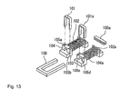
- Fig. 13 is an exploded perspective view of such a high voltage transformer as disclosed in the aforementioned Japanese Patent Application Laid-Open No. H10-241972 .
- a closed magnetic path is constituted by a U-core 100 and an I-core 100a
- primary windings 101 and 101a are each constituted by a sheet coil of a thin conductive metal tape formed into squared-U shape.
- the primary winding 101 has its respective leg portions of the squared-U inserted through openings 105a and 105b formed at a flange 104 of a bobbin
- the primary winding 101a has its respective leg portions inserted through openings 105c and 105d formed at a flange 104a of another bobbin.
- Secondary windings 102 and 102a each include two tiers of single-layer alignment windings so that the electric capacity is increased while the insulation between adjacent wires is enhanced and at the same time the potential difference between adjacent wires is reduced, whereby a short circuit attributable to the potential difference is decreased. Also, since the magnetic circuit has a closed magnetic path, the high voltage transformer can be downsized.
- the primary winding is capable of carrying a large current, but because the primary winding and the secondary winding are disposed in a tandem arrangement along the same axis, there is provided a poor electromagnetic coupling therebetween. Accordingly, the high voltage transformer of Fig. 13, when adapted as a transformer with a high coupling between the primary and secondary windings, namely a tightly-coupled transformer, is caused to behave with deteriorated performance. Also, the sheet coil constituting the primary winding and inserted in the opening of the bobbin must be coated with a thick resin in order to secure insulation, which deteriorates the workability.
- the present invention has been made in light of the problems described above, and it is an object of the present invention to provide a high voltage transformer in which a primary winding can be positioned selectively and optimally with respect to a secondary winding, and so the primary winding is allowed to be tightly coupled electromagnetically to the secondary winding, while the workability in assembly is improved.
- a high voltage transformer which includes: a bobbin including a spool body with a hollow; a magnetic core formed of magnetic material and disposed at the hollow of the bobbin; and a primary winding and a secondary winding both disposed around the spool body of the bobbin.
- the bobbin further includes terminal blocks which are disposed respectively at the both ends of the spool body and which each have a plurality of terminals;
- the primary winding is composed of one or more thin conductive sheet coils coated with resin;
- the secondary winding is wound on the outer circumferential surface of the spool body; and a means for fixedly positioning the thin conductive sheet coil is provided either at an outer circumference of the bobbin or at a board on which the bobbin is mounted, wherein the primary winding can be disposed around the secondary winding selectively at an optimal position by the positioning means thereby modulating an electromagnetic coupling between the primary winding and the secondary winding.
- the thin conductive sheet coil may be coated by insert-molding, and the secondary winding may be split into a plurality of separate windings where the width of the conductive sheet coil of the primary winding is substantially equal to the width of each separate winding of the secondary winding.
- the positioning means may be constituted either by a plurality of flanges provided on the bobbin so as to split the secondary winding into a plurality of separate windings and also projections provided respectively at the flanges, or by a plurality of holes which are provided at the board and though which terminal portions of the thin conductive sheet coil are inserted.
- the primary winding may include one or two thin conductive sheet coils and be disposed at the low voltage side of the secondary winding, and a boss for positioning the bobbin onto the board may be provided at the bottom of each of the terminal blocks of the bobbin.
- the spool body may have an indented portion provided at an area corresponding to the position of the primary winding, and the secondary winding may have an outer diameter smaller at the portion corresponding to the intended portion than at the other portion clear of the primary winding.
- at least the low voltage side of the secondary winding may be constituted by a diagonally overlapped winding.
- the primary winding and the secondary winding can be disposed close to each other on the same axis, the electromagnetic coupling between the primary and secondary windings is enhanced, which improves the efficiency of the transformer. Also, since the primary winding is composed of thin conductive sheet coils coated with resin, the insulation from the secondary winding is ensured, the assembling workability is enhanced, and the number and arrangement of the coils can be arbitrarily and optimally selected allowing the coupling coefficient of the transformer to be adjusted. Consequently, the transformer characteristics and the component standardization can be achieved.
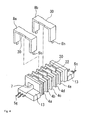
- a high voltage transformer includes a bobbin 1 which is formed of resin, such as liquid crystal polymer (LCP), and which integrally includes a spool body 3 and two terminal blocks 2a and 2b located at the respective ends of the spool body 3, and one terminal block 2a thereof is provided with terminals 5a, 5b, 5c and 5d while the other terminal block 2b is provided with terminals 5e, 5g and 5f.
- LCP liquid crystal polymer
- the spool body 3 is partitioned by a plurality of flanges 4a to 4e into a plurality (six in Figs. 1 and 2) of sections a to f disposed along the axial direction, and has a primary winding 8 and a secondary winding 6 disposed therearound as shown in Fig. 2.
- each of the flanges 4a to 4e has a projection 20 at its top side (upper side in Fig.
- the secondary winding 6 has a slit groove 22 at either its top or bottom side (not necessarily on the flange 4a) for enabling the secondary winding 6 to be put into a split structure with separate windings 6a, 6b, 6c, 6d and 6e which are disposed at the sections b, c, d, e and f, respectively.
- the sections b to f of the spool body 3 have a uniform width so that the separate windings 6a to 6e have substantially the same voltage.
- the terminals 5a, 5b, 5c and 5d are for the secondary winding 6, and the terminal 5e is for ground (GND).
- a tertiary winding for example, feedback winding, may be disposed at the section a, in which case the terminals 5f and 5g are available for use with the tertiary winding.
- the spool body 3 has a hollow 7, and the terminal blocks 2a and 2b each have a boss 9 at the bottom as shown in Figs. 2 and 3.
- the primary winding 8 arranged overlappingly around part of the secondary winding 6 is basically composed of two sheet coils 8a and 8b, which are coated with a resin 12 as shown in a magnified view of a portion A (circled) for ensuring insulation between the primary winding 8 and the secondary winding 6.
- the sheet coil 8a/8b is a pressed part with a configuration of squared-U and has two terminal portions 5h integrally extending from the respective leg tips of the squared-U.
- the sheet coil 8a/8b, except the terminal portions 5h, is coated with the resin 12 having a thickness of about 0.5 mm by insert molding.
- Figs. 6(a), 6(b) and 6(c) show examples of common configurations of sheet coils.
- the sheet coil 8a/8b of the primary winding 8 is configured as shown in Fig. 6(b), and both of the sheet coils 8a and 8b are arranged at the low voltage side of the secondary winding 6.
- the sheet coils 8a and 8b each have two recesses 30 (refer to Fig.
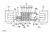
- the terminal blocks 2a and 2b of the bobbin 1 each have an elevated portion 13, which serves as a guide to allow an easy insertion of a magnetic core 11 (refer to Fig. 5) into the hollow 7 of the bobbin 1.
- grooves 10b and 10c are provided for accommodating lead wires of the tertiary winding (if provided), grooves 10d and 10e are provided for lead wires of the secondary winding 6, and a groove 10a is for a wire leading to the terminal 5e for GND.
- the aforementioned magnetic cores 11 are made of ferrite and are both constituted by E-cores in the embodiment shown in Fig. 5, which have their respective center legs 11a inserted in the hollow 7 of the bobbin 1 and fixedly attached to each other by adhesive.
- the magnetic cores 11 do not have to be constituted by two E-cores, and may alternatively be constituted by, for example, one E-core and one I-core, or two U-cores.
- two U-cores 11 may have their respective one legs inserted in one bobbin 1 as shown in Fig. 7(a) and adhesively connected to each other, or two U-cores 11 may have their respective both legs inserted respectively in two bobbins 1 as shown in Fig. 7(b) and adhesively connected to each other.
- This positioning means allows the primary winding 8 constituted by one or two of the sheet coils 8a and 8b to be fixedly set at sections predetermined at either the low voltage side or the high voltage side of the secondary winding 6 according to the transformer characteristics intended.
- the bobbin 1, with the cores 11 fitted therein, is fixedly attached to a printed circuit board of a backlight inverter circuit, and the like, and the terminals of the bobbin 1 are soldered to the printed circuit board.
- the bosses 9 formed at the bottom faces of the terminal blocks 2a and 2b are fitted into respective holes 18 formed at a printed circuit board P (refer to Fig. 8), whereby the bobbin 1 can be readily attached at the right place on the printed circuit board P.
- the separate windings 6a to 6e of the secondary winding 6 are wound respectively at the sections b to f of the spool body 3 of the bobbin 1, the center legs 11a of the E-cores 11 are inserted in the hollow 7 of the spool body 3 (refer to Fig. 3) for assembly, and then the primary winding 8 is set at the predetermined sections when the bobbin 1 is attached to the printed circuit board.
- All the sections a to f are uniform in depth as shown in Fig. 2, but it may alternatively be arranged such that sections at which the primary winding is located are deeper than the other sections.
- an indented portion 15 is provided at an area of a spool body 3 having a primary winding 8 therearound, and a secondary winding 6 is wound such that the outer diameter at a portion thereof having the primary winding 8 therearound is smaller than the outer diameter at the other portion thereof.
- the primary winding 8 has its radial dimension reduced so as to be aligned with the radial dimension of the secondary winding 6, whereby the primary winding 8 does not protrude beyond the diameter of a bobbin.
- the primary winding 8 is duly positioned with respect to the secondary winding 6 by means of the flanges 4a to 4e and the projections 20 formed at the top sides of the flanges 4a to 4e in the embodiment, but may be positioned by other methods or means.
- a plurality of holes 40 formed at the printed circuit board P as shown in Fig. 8 are an alternative means, wherein the sheet coil 8a of the primary winding 8 is set around the section b having the separate winding 6a of the secondary winding 6, and the terminal portions 5h are inserted through the holes 40 formed at the wiring pattern on the printed circuit board P, whereby the primary winding 8 (8a) is provided around the secondary winding 6 (6a) while duly mounted on the printed circuit board P.
- the primary winding 8 can be set at any sections thereby readily and optimally modulating the transformer characteristics.
- the primary winding 8 may be composed of one or a plurality of sheet coils located at desired places around the secondary winding 6.
- the sheet coil for the primary winding 8 is coated with resin thereby ensuring insulation.
- the primary winding 8 can be composed of sheet coils which have the same configuration, and which therefore can be produced as common parts.
- the terminal portions 5h of the sheet coil 8a/8b extend straight as shown in Fig. 6(b) and are inserted though the holes 40 formed at the wiring pattern of the printed circuit board P in the embodiment, but may alternatively be bent as shown in Fig. 6 (a) so as to make contact with the wiring pattern.
- the plurality of sections a to f are formed at the spool body 3 of the bobbin 1, but the present invention is not limited to such a structure, and the bobbin 1 may have a single section as shown in Figs. 9(a) and 9(b) at the spool body 3, where at least the high voltage side of the secondary winding 6 is constituted by a diagonally overlapped winding in order to ensure a sufficient withstand voltage.
- the single section may have the indented portion 15 at an area having the primary winding 8 around as shown in Fig. 9(b), whereby the primary winding 8 can be downsized so as to have an outside diameter equal to the outside diameter of the secondary winding 6 defined at an area at which the primary winding 8 is absent, thus enabling downsizing of the high voltage transformer.
- the sheet coil 8a/8b of the primary winding 8 of the embodiment is provided with the two recesses 30 located at respective middle regions of the both sides of the bridge portion of the squared-U structure so as to directly oppose each other as shown in Fig. 4, but the bridge portion of the sheet coil of the primary winding 8 may alternatively have two recesses 31 and 32 which are arranged at respective sides of the bridge portion so as to diagonally oppose each other as shown in Fig. 10.
- the projection 20, which is provided at the top side of the flange 4 in the embodiment may be located at a lateral side of the flange 4, or alternatively the flange 4 may be replaced by a plurality of pins for positioning the primary winding 8.
- the sections b to f of the spool body 3 having the secondary winding 6 thereat have a uniform width in the embodiment, but may alternatively have different widths.
- a spool body 3 has six sections a to f having a secondary winding 6, wherein the sections c to f positioned at the high voltage side of the secondary winding 6 have a reduced width compared with the sections a and b positioned at the low voltage side of the secondary winding 6, whereby the high voltage side can be provided with an increased number of sections thus splitting the secondary winding 6 into an increased number of separate windings at the high voltage side.
- the sheet coil of the primary winding 8 may have its configuration changed to the geometry of the sections corresponding thereto, or may be disposed atop the flanges 4e and 4f, wherein the sheet coil of the primary winding 8 can be optimally positioned around the secondary winding 6 by means of terminal pin holes 18 formed at the printed circuit board P at an interval d which is smaller than an interval D defined at the low voltage side of the secondary winding 6.
- the primary winding 8 can be positioned by means of projections and recesses which are formed at the flanges 4a to 4f of the bobbin 1 and at the sheet coil of the primary winding 8, or vice versa, or alternatively by a plurality of holes which are formed at arbitrary places of the printed circuit board P.
- sections a and b have their width increased and are provided with a step 4', whereby the secondary winding 6 can be structured so as to have its radial dimension reduced at the low voltage side thus enabling the primary winding 8 to be firmly disposed substantially flush with the flanges of the bobbin 1 while the total turn number of the secondary winding 6 remains unchanged.
- the primary winding 8 can be disposed flush with the outer dimension of the bobbin 1, whereby the height of the high voltage transformer mounted on the printed circuit board can be minimized.
Landscapes
- Engineering & Computer Science (AREA)
- Power Engineering (AREA)
- Coils Of Transformers For General Uses (AREA)
- Insulating Of Coils (AREA)
- Coils Or Transformers For Communication (AREA)
Applications Claiming Priority (2)
| Application Number | Priority Date | Filing Date | Title |
|---|---|---|---|
| JP2004336552A JP4547703B2 (ja) | 2004-11-19 | 2004-11-19 | 高圧トランス |
| PCT/JP2005/020363 WO2006054453A1 (ja) | 2004-11-19 | 2005-11-07 | 高圧トランス |
Publications (1)
| Publication Number | Publication Date |
|---|---|
| EP1814129A1 true EP1814129A1 (en) | 2007-08-01 |
Family
ID=36406998
Family Applications (1)
| Application Number | Title | Priority Date | Filing Date |
|---|---|---|---|
| EP05800337A Withdrawn EP1814129A1 (en) | 2004-11-19 | 2005-11-07 | High-voltage transformer |
Country Status (4)
| Country | Link |
|---|---|
| US (1) | US20080024261A1 (https=) |
| EP (1) | EP1814129A1 (https=) |
| JP (1) | JP4547703B2 (https=) |
| WO (1) | WO2006054453A1 (https=) |
Cited By (2)
| Publication number | Priority date | Publication date | Assignee | Title |
|---|---|---|---|---|
| KR101101590B1 (ko) | 2010-05-24 | 2012-01-02 | 삼성전기주식회사 | 트랜스포머 |
| US8324999B2 (en) | 2007-03-29 | 2012-12-04 | E2V Technologies (Uk) Limited | High frequency transformer for high voltage applications |
Families Citing this family (19)
| Publication number | Priority date | Publication date | Assignee | Title |
|---|---|---|---|---|
| DE112006003946B4 (de) * | 2006-12-20 | 2017-10-26 | SUMIDA Components & Modules GmbH | Induktives Bauteil mit einem Spulenkörper mit integrierter Wicklung |
| JP4973230B2 (ja) * | 2007-02-20 | 2012-07-11 | パナソニック株式会社 | トランス |
| KR101235700B1 (ko) * | 2008-04-30 | 2013-02-21 | 엘지디스플레이 주식회사 | 트랜스포머 및 이를 포함하는 액정표시장치용 백라이트구동부 |
| TWI351042B (en) * | 2008-07-15 | 2011-10-21 | Delta Electronics Inc | Combination structure of circuit carrier and transformer |
| JP5115537B2 (ja) * | 2009-10-29 | 2013-01-09 | Tdk株式会社 | トランス |
| JP5703669B2 (ja) * | 2010-10-01 | 2015-04-22 | ミツミ電機株式会社 | トリガコイル |
| KR101197796B1 (ko) * | 2011-06-30 | 2012-11-05 | 삼성전기주식회사 | 트랜스포머 및 이를 구비하는 디스플레이 장치 |
| JP5715258B2 (ja) * | 2011-08-24 | 2015-05-07 | スミダコーポレーション株式会社 | トランス |
| KR101405406B1 (ko) * | 2013-01-03 | 2014-06-11 | 크로바하이텍(주) | 중첩 부분을 통해서 전기적으로 권취되는 배선들을 포함하는 트랜스포머 |
| EP2869317B1 (en) * | 2013-10-30 | 2017-05-03 | Korea Electro Technology Research Institute | Transformer and high voltage power supply apparatus having the same |
| CN103617879A (zh) * | 2013-10-31 | 2014-03-05 | 昱京科技股份有限公司 | 变压器结构及其适用的整流电路 |
| JP6388769B2 (ja) * | 2014-01-16 | 2018-09-12 | Fdk株式会社 | トランス |
| TW201432742A (zh) * | 2014-04-17 | 2014-08-16 | Yujing Technology Co Ltd | 具耦合調整線槽的線架結構 |
| JP6150844B2 (ja) * | 2015-05-21 | 2017-06-21 | 三菱電機株式会社 | 電磁誘導機器 |
| JP6648535B2 (ja) * | 2016-01-22 | 2020-02-14 | 富士電機株式会社 | 直流電源装置 |
| CN107316738A (zh) * | 2016-04-26 | 2017-11-03 | 广州喆嘉科技有限公司 | 高压包及其生产工艺 |
| JP7082267B2 (ja) * | 2017-11-15 | 2022-06-08 | オムロン株式会社 | トランス及びdc-dcコンバータ |
| US10553339B1 (en) * | 2018-03-30 | 2020-02-04 | Universal Lighting Technologies, Inc. | Common-mode choke with integrated RF inductor winding |
| WO2020168101A1 (en) * | 2019-02-13 | 2020-08-20 | Astronics Advanced Electronic Systems Corp. | Integrated transformer with low ac losses and impedance balanced interface |
Family Cites Families (10)
| Publication number | Priority date | Publication date | Assignee | Title |
|---|---|---|---|---|
| JPS5849421U (ja) * | 1981-09-29 | 1983-04-04 | 東芝ライテック株式会社 | 電磁装置 |
| JPH0438020U (https=) * | 1990-07-27 | 1992-03-31 | ||
| JPH04348507A (ja) * | 1991-05-27 | 1992-12-03 | Matsushita Electric Ind Co Ltd | コイル部品 |
| JPH0869931A (ja) * | 1994-08-29 | 1996-03-12 | Matsushita Electric Works Ltd | 電磁装置 |
| US5847518A (en) * | 1996-07-08 | 1998-12-08 | Hitachi Ferrite Electronics, Ltd. | High voltage transformer with secondary coil windings on opposing bobbins |
| JP2998675B2 (ja) * | 1997-01-29 | 2000-01-11 | 松下電器産業株式会社 | トランスおよびその製造方法 |
| JP2000150267A (ja) * | 1998-11-18 | 2000-05-30 | Matsushita Electric Ind Co Ltd | トランス |
| JP4506078B2 (ja) * | 2002-12-24 | 2010-07-21 | パナソニック電工株式会社 | 電磁装置および高電圧発生装置 |
| US7375609B2 (en) * | 2003-09-29 | 2008-05-20 | Tamura Corporation | Multilayer laminated circuit board |
| JP2004253814A (ja) * | 2004-04-12 | 2004-09-09 | Kijima:Kk | 小形トランス |
-
2004
- 2004-11-19 JP JP2004336552A patent/JP4547703B2/ja not_active Expired - Fee Related
-
2005
- 2005-11-07 WO PCT/JP2005/020363 patent/WO2006054453A1/ja not_active Ceased
- 2005-11-07 US US11/664,820 patent/US20080024261A1/en not_active Abandoned
- 2005-11-07 EP EP05800337A patent/EP1814129A1/en not_active Withdrawn
Non-Patent Citations (1)
| Title |
|---|
| See references of WO2006054453A1 * |
Cited By (2)
| Publication number | Priority date | Publication date | Assignee | Title |
|---|---|---|---|---|
| US8324999B2 (en) | 2007-03-29 | 2012-12-04 | E2V Technologies (Uk) Limited | High frequency transformer for high voltage applications |
| KR101101590B1 (ko) | 2010-05-24 | 2012-01-02 | 삼성전기주식회사 | 트랜스포머 |
Also Published As
| Publication number | Publication date |
|---|---|
| US20080024261A1 (en) | 2008-01-31 |
| JP4547703B2 (ja) | 2010-09-22 |
| JP2006147885A (ja) | 2006-06-08 |
| WO2006054453A1 (ja) | 2006-05-26 |
Similar Documents
| Publication | Publication Date | Title |
|---|---|---|
| EP1814129A1 (en) | High-voltage transformer | |
| KR101085665B1 (ko) | 트랜스포머 | |
| JP4899127B2 (ja) | インバータトランス | |
| US8432245B2 (en) | Power module and circuit board assembly thereof | |
| US8102237B2 (en) | Low profile coil-wound bobbin | |
| US6894596B2 (en) | Inverter transformer to light multiple lamps | |
| JP2000068132A (ja) | インバータトランス | |
| JP2005311227A (ja) | 高圧トランス | |
| US7295091B2 (en) | Leakage transformer | |
| WO2001054150A1 (en) | Inverter transformer | |
| JP2004297862A (ja) | 2出力インバータトランス | |
| JP2001223123A (ja) | インダクタンス部品 | |
| JPH10208949A (ja) | インバータトランス | |
| JP5070848B2 (ja) | トランス | |
| KR200338261Y1 (ko) | 트랜스포머 | |
| JP4849250B2 (ja) | トランス | |
| JP4188979B2 (ja) | リーケージトランス | |
| JP2006147688A (ja) | 高圧トランス | |
| KR100808071B1 (ko) | 다출력 고압 트랜스포머 | |
| JP4586249B2 (ja) | 昇圧トランスおよびそれを用いた電気装置 | |
| KR20030015957A (ko) | 인버터 회로용 변압기 | |
| JP2007173455A (ja) | 巻線部品 | |
| JPH0742110U (ja) | トロイダルトランス | |
| JP2006108573A (ja) | 多連トランス | |
| CN121641656A (zh) | 线圈装置 |
Legal Events
| Date | Code | Title | Description |
|---|---|---|---|
| PUAI | Public reference made under article 153(3) epc to a published international application that has entered the european phase |
Free format text: ORIGINAL CODE: 0009012 |
|
| 17P | Request for examination filed |
Effective date: 20070519 |
|
| AK | Designated contracting states |
Kind code of ref document: A1 Designated state(s): DE FR GB IT NL |
|
| RIN1 | Information on inventor provided before grant (corrected) |
Inventor name: WEGER, ROBERT Inventor name: SUZUKI, MITSUAKI,C/O MINEBEA CO., LTD. Inventor name: SHINMEN, HIROSHI,C/O MINEBEA CO., LTD. |
|
| DAX | Request for extension of the european patent (deleted) | ||
| STAA | Information on the status of an ep patent application or granted ep patent |
Free format text: STATUS: THE APPLICATION HAS BEEN WITHDRAWN |
|
| 18W | Application withdrawn |
Effective date: 20091104 |