EP1812674B1 - Stellantrieb - Google Patents
Stellantrieb Download PDFInfo
- Publication number
- EP1812674B1 EP1812674B1 EP05799628.2A EP05799628A EP1812674B1 EP 1812674 B1 EP1812674 B1 EP 1812674B1 EP 05799628 A EP05799628 A EP 05799628A EP 1812674 B1 EP1812674 B1 EP 1812674B1
- Authority
- EP
- European Patent Office
- Prior art keywords
- actuating arm
- flap
- base body
- actuating
- arm
- Prior art date
- Legal status (The legal status is an assumption and is not a legal conclusion. Google has not performed a legal analysis and makes no representation as to the accuracy of the status listed.)
- Expired - Lifetime
Links
Images



Classifications
-
- E—FIXED CONSTRUCTIONS
- E05—LOCKS; KEYS; WINDOW OR DOOR FITTINGS; SAFES
- E05D—HINGES OR SUSPENSION DEVICES FOR DOORS, WINDOWS OR WINGS
- E05D15/00—Suspension arrangements for wings
- E05D15/26—Suspension arrangements for wings for folding wings
- E05D15/262—Suspension arrangements for wings for folding wings folding vertically
-
- E—FIXED CONSTRUCTIONS
- E05—LOCKS; KEYS; WINDOW OR DOOR FITTINGS; SAFES
- E05D—HINGES OR SUSPENSION DEVICES FOR DOORS, WINDOWS OR WINGS
- E05D15/00—Suspension arrangements for wings
- E05D15/40—Suspension arrangements for wings supported on arms movable in vertical planes
- E05D15/46—Suspension arrangements for wings supported on arms movable in vertical planes with two pairs of pivoted arms
-
- E—FIXED CONSTRUCTIONS
- E05—LOCKS; KEYS; WINDOW OR DOOR FITTINGS; SAFES
- E05D—HINGES OR SUSPENSION DEVICES FOR DOORS, WINDOWS OR WINGS
- E05D7/00—Hinges or pivots of special construction
- E05D7/12—Hinges or pivots of special construction to allow easy detachment of the hinge from the wing or the frame
- E05D7/123—Hinges or pivots of special construction to allow easy detachment of the hinge from the wing or the frame specially adapted for cabinets or furniture
- E05D7/125—Hinges or pivots of special construction to allow easy detachment of the hinge from the wing or the frame specially adapted for cabinets or furniture the hinge having two or more pins
-
- E—FIXED CONSTRUCTIONS
- E05—LOCKS; KEYS; WINDOW OR DOOR FITTINGS; SAFES
- E05Y—INDEXING SCHEME ASSOCIATED WITH SUBCLASSES E05D AND E05F, RELATING TO CONSTRUCTION ELEMENTS, ELECTRIC CONTROL, POWER SUPPLY, POWER SIGNAL OR TRANSMISSION, USER INTERFACES, MOUNTING OR COUPLING, DETAILS, ACCESSORIES, AUXILIARY OPERATIONS NOT OTHERWISE PROVIDED FOR, APPLICATION THEREOF
- E05Y2201/00—Constructional elements; Accessories therefor
- E05Y2201/60—Suspension or transmission members; Accessories therefor
- E05Y2201/622—Suspension or transmission members elements
- E05Y2201/624—Arms
-
- E—FIXED CONSTRUCTIONS
- E05—LOCKS; KEYS; WINDOW OR DOOR FITTINGS; SAFES
- E05Y—INDEXING SCHEME ASSOCIATED WITH SUBCLASSES E05D AND E05F, RELATING TO CONSTRUCTION ELEMENTS, ELECTRIC CONTROL, POWER SUPPLY, POWER SIGNAL OR TRANSMISSION, USER INTERFACES, MOUNTING OR COUPLING, DETAILS, ACCESSORIES, AUXILIARY OPERATIONS NOT OTHERWISE PROVIDED FOR, APPLICATION THEREOF
- E05Y2600/00—Mounting or coupling arrangements for elements provided for in this subclass
- E05Y2600/50—Mounting methods; Positioning
- E05Y2600/52—Toolless
- E05Y2600/53—Snapping
-
- E—FIXED CONSTRUCTIONS
- E05—LOCKS; KEYS; WINDOW OR DOOR FITTINGS; SAFES
- E05Y—INDEXING SCHEME ASSOCIATED WITH SUBCLASSES E05D AND E05F, RELATING TO CONSTRUCTION ELEMENTS, ELECTRIC CONTROL, POWER SUPPLY, POWER SIGNAL OR TRANSMISSION, USER INTERFACES, MOUNTING OR COUPLING, DETAILS, ACCESSORIES, AUXILIARY OPERATIONS NOT OTHERWISE PROVIDED FOR, APPLICATION THEREOF
- E05Y2900/00—Application of doors, windows, wings or fittings thereof
- E05Y2900/20—Application of doors, windows, wings or fittings thereof for furniture, e.g. cabinets
Definitions
- the present invention relates to an actuator for moving a flap of a piece of furniture having the features of the preamble of claim 1 or 2.
- Actuators of this type are usually attached to a side wall of a furniture body and serve to move a hinged on the actuating arm furniture flap from an open to the closed position or in the reverse direction.
- the actuator arm is usually acted upon by a spring device, which brings with not hinged furniture flap the risk of injury, since the relatively light actuator arm can knock out like a bullet.
- the main body with the pivotally mounted actuating arm complicates the handling of the actuator and also requires large packaging for logistical reasons.
- WO 01/08854 A1 discloses all features of the preamble of claims 1 and 2, a tool cabinet with a folding flap has become known, which is movable via a gas spring.
- the two end portions of the gas spring are each held by a ball in a C-shaped retaining frame.
- the EP 0 763 642 A1 describes a hinge for glass doors, wherein an intermediate piece relative to a base plate can be suspended and locked by a spring-loaded rocker arm.
- Object of the subject invention is therefore to propose an actuator of the type mentioned above while avoiding the disadvantages mentioned above.
- the actuating arm can be articulated in a simple manner to or in the main body (core) and removed again if necessary.
- the packaging sizes are reduced, since each part can be packaged separately - ie base body and actuator arm.
- the handling of the actuator is thereby significantly improved because no protruding part complicates handling with the actuator.
- the risk of a deflecting actuator arm with hinged furniture flap can be largely avoided, since the actuator arm in the critical moments in which no flap on the actuator arm stores, can be easily removed.
- a particular advantage lies in the fact that different actuating arms can be articulated according to the size and weight of the furniture flap with the same design of the fastening device to the same body, resulting in a high variability in different mounting situations.
- the mechanical latching connection has two latching parts which can be latched with one another, with one latching part being able to be hooked into the other latching part and subsequently latched thereto by being pivoted upwards.
- the actuator arm on the body and / or on the furniture flap can be clipped in a simple manner.
- a locking part of the mechanical latching connection has a spring-loaded catch which can be latched to the other latching part.
- the second mechanical latching connection has a resilient retaining lug, which is provided for fixing the actuating arm and which can be disengaged from the actuator arm by pressure against its resilient force.
- the actuating arm In order to adapt the actuating arm to different furniture flaps and / or with different mounting position of the main body on a furniture side wall in terms of its length, it may be advantageous if the actuating arm consists of at least two relatively displaceable or mutually fixable parts.
- Such adjustable-length control arm levers are known in the art and may have a variety of configurations.
- the relative position of the parts to one another can be fixed by a clamping connection.
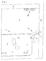
- Fig. 1 shows a side view of a furniture body 4, on whose side wall a base body 2 of an actuator 1 according to the invention is attached.
- the base body 2 has a latching part 7, which is mounted at a pivot point 9 and part of the fastening device 8.
- a control arm 3 not shown for reasons of clarity can be mechanically locked.
- This actuator arm 3 can thus be hinged to an end portion on the one hand with the locking part 7, on the other hand to a flap 6 shown as an example and moves it from the Closed position in an open position and vice versa.
- a base plate 10 is screwed to the - as already known in the prior art - a hinge can be clipped in a simple manner so that the flap 6 can be pivoted about a horizontal axis in the region of the cabinet cover 5.
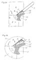
- Fig. 2a shows a section Fig. 1 with partially fixed actuating arm 3
- Fig. 2b shows an enlarged detail view Fig. 2a
- the movably mounted on the base body 2 locking part 7 has two or more groove-shaped grooves 11, 11 ', which are provided for receiving corresponding parts of the locking part 7' of the actuating arm 3.
- the locking member 7 ' is first hooked into the grooved groove 11 of the locking member 7 and then pivoted so far until the catch 12 of the locking member 7' completely snaps into the second groove-shaped groove 11 'of the locking member 7.
- the locking part 7 ' has a spring-loaded catch 12.
- an additional groove-shaped groove 13 may be provided, which is provided for receiving a corresponding bolt part of the locking part 7 '.
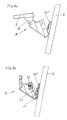
- Fig. 3 shows a side view of a side wall of the furniture body 4, on which the base body 2 of the actuator 1 is mounted. In the figure shown, the actuating arm 3 is completely locked to the latching part 7 of the base body 2.
- Fig. 4 shows a side view of the actuator 1, the lever 3 consists of at least two relatively displaceable or mutually fixable parts 3, 3 '.
- the relative position of the two parts 3, 3 'to each other can be fixed by a clamping connection 15, preferably by means of a rocker arm.
- a base plate 10 screwed to the hinge 14 is anklippsbar.
- an upper part flap 6 ' is mounted on the hinge 14.
- a further base plate 10 ' is provided on the upper partial flap 6', on which an additional partial flap 6 "can be articulated.
- Fig. 5 shows the embodiment Fig. 4 , with an additionally hinged partial flap 6 ", which is connected to the upper partial flap 6 'via a hinge 14' which is clipped onto the base plate 10 '. which is provided for releasably connecting the actuating arm 3 with a base body 2 'fixed to the lower partial flap 6 ".
- Fig. 6a shows the control arm 3, at its end a fastening device 8 'for releasably connecting with a base 6 attached to the flap body 2' is arranged.
- Fig. 6b shows a sectional view along the axis EE Fig. 6a ,
- the base body 2 ' has a fastening flange 16 which is screwed to the flap 6 via openings 17, 17'.
- the base body 2 ' comprises a riveted bolt 18 on which a holding part 19 of the actuating arm 3 is attached.
- This mechanical latching connection has a resilient retaining lug 20 which is provided for fixing the actuating arm 3 and which can be disengaged by pressure against its resilient force in the direction of the arrow A shown by the holding part 19 of the actuating arm 3.
- Fig. 7a shows the flap-side end region of the actuating arm 3
- Fig. 7b an enlarged detail of the circle Fig. 7a
- a fastening device 8 ' is provided, which is analogous as in Fig. 2a, 2b a spring-loaded catch 12 has.
- the bolt 21 is first hooked into a corresponding grooved groove on the base body 2 ', not shown, and then finally locked with the catch 12 by pivoting.
- the bolt 22 serves for additional centering or for stabilizing the actuating arm 3 mounted on the base body 2 '.
- Fig. 8a shows the embodiment Fig. 7a, 7b in which the flap-side fastening device 8 'has already been clipped onto a base plate 10 "mounted on the rear side of the lower partial flap 6".
- the two length-adjustable parts 3 ', 3 "of the lever 3 can be optimally adapted to the required length and locked by means of the clamping connection 15.
- Fig. 8b shows the embodiment Fig. 6a, 6b , wherein the flap-side fastening device 8 'with its holding part 19 to a - as in Fig. 6b shown - pin 18 has been plugged and held with the retaining lug 20.
- Fig. 9a shows a side view of the flap-side fastening device 8 'for connection to a flap 6, Fig. 9b a vertical section Fig. 9a , Regarding Fig. 7b the bolt 21 is mounted in a corresponding groove of the base plate 10 ", Subsequently, the fastening device 8 'is pivoted towards the base plate 2' and the resilient detent 12 is completely locked to the base plate 10 "For additional centering or stabilization, the central centering pin 22 is provided, which in the latched position also accommodates in a corresponding groove of the Base plate 10 "finds.
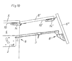
- Fig. 10 shows an exemplary Hochfaltklappe 6 ', 6 ", which is hinged horizontally on the underside of the cabinet lid 5.
- the lower part of the flap 6" is connected to the upper part of the flap 6 'also via a hinge 14', which is clipped onto a base plate 10 'attached.
- the main body 2 of the actuator 1 is attached to a side wall of a furniture body 4.
- the actuator arm 3 has on its two end portions fastening devices 8, 8 ', which are provided for releasably connecting the actuating arm 3 with the base body 2 and with the unillustrated base plate 10' on the back of the lower part of the flap 6 ". if all the parts to be fastened, that is to say actuating arm 3 and hinges 14, 14 ', have the same fastening mechanism, thereby achieving high variability and interchangeability while minimizing the constructional outlay.
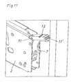
- Fig. 11 shows a perspective view of the base body 2, which is fastened to the side wall of a furniture body 4. This has a pivotally hinged latching part 7, wherein two groove-shaped grooves 11 and 11 'are provided for receiving corresponding parts of the fastening device 8 of the actuating arm 3.
- the centering groove 13 serves to receive the bolt 22 of the fastening device 8.
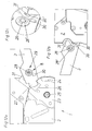
- Fig. 12a - 12c show a further embodiment of the invention in different views.
- Fig. 12a shows - as known per se - an actuator 1 with a pivotably mounted on the base body 2 at the pivot point 25 control cam 23 and associated adjusting contour 24.
- the fastening device 8 has a screw 29.
- This screw 29 comprises a screw 28, which is preferably preassembled on the actuator arm 3.
- the retaining lug 27 formed or arranged on the actuating arm 3 is first suspended in a corresponding recess 26 of the control cam 23 by pivoting the actuating arm 3.
- the recess 26 is designed so that the retaining lug 27 is essentially a play-free recording therein.
- Fig. 12b shows a partial section of the back Fig. 12a ,
- the screw 28 which is in engagement with the threaded nut 28 ', is hooked upon pivoting of the actuating arm 3 in the hook-shaped element 31. Subsequently, by tightening the screw 28, the hook-shaped element 31 between the actuating arm 3 and threaded nut 28 'jammed.
- Fig. 12c shows a detailed view Fig. 12b in a perspective view.
- Fig. 13a and Fig. 13b show the actuator arm 3, which is completely mounted on the base body 2 and on the control cam 23.
- Fig. 13a shows a side view, wherein the retaining lug 27 of the actuating arm 3 is received without play in the recess 26 of the control cam 23 by pivoting.
- the catch 30 ' is in the opening 30, which for safety reasons in addition to the already described screw locking of the actuator arm 3 is achieved with the base body 2.
- Fig. 13b shows the actuator 1 in a perspective view.
- the actuator arm 3 can be fixed non-positively.
- the present invention is not limited to the embodiments shown, but includes all variants and technical equivalents that may fall within the scope of the following claims. Also, the location information chosen in the description, such as top, bottom, side, etc. based on the usual installation position of the actuator 1 and on the immediately described and illustrated figure and are to be transferred to a new position analogously to a change in position.
Landscapes
- Engineering & Computer Science (AREA)
- Mechanical Engineering (AREA)
- Hinges (AREA)
- Closing And Opening Devices For Wings, And Checks For Wings (AREA)
- Furniture Connections (AREA)
- Power-Operated Mechanisms For Wings (AREA)
Description
- Die vorliegende Erfindung bezieht sich auf einen Stellantrieb zum Bewegen einer Klappe eines Möbels mit den Merkmalen des Oberbegriffs des Patentanspruchs 1 oder 2.
- Stellantriebe dieser Art werden üblicherweise an einer Seitenwand eines Möbelkorpus befestigt und dienen dazu, eine an dem Stellarm angelenkte Möbelklappe von einer Offen- in die Schließstellung bzw. in die umgekehrte Richtung zu bewegen. Der Stellarm wird üblicherweise von einer Federvorrichtung beaufschlagt, was bei nicht angelenkter Möbelklappe die Gefahr von Verletzungen mit sich bringt, da der relativ leichte Stellarm gewehrkugelartig ausschlagen kann. Der Grundkörper mit dem schwenkbar gelagerten Stellarm erschwert das Handling des Stellantriebes und erfordert überdies aus logistischen Gründen große Verpackungen.
- Aus der
DE 24 54 897 A1 ist ein Beschlag für eine nach oben verschwenkbare Möbelklappe bekannt geworden, bei dem ein Hebelführungsglied lösbar mit einem an der Klappe montierten Gelenkbock verbindbar ist. Die Montage bzw. Demontage des Hebelführungsgliedes am bzw. vom Gelenkbock gestaltet sich dabei als relativ aufwändig. - Aus der
WO 01/08854 A1 - Die
EP 0 763 642 A1 beschreibt ein Scharnier für Glastüren, wobei ein Zwischenstück relativ zu einer Grundplatte einhängbar und über einen federbelasteten Kipphebel verrastbar ist. - Aufgabe der gegenständlichen Erfindung ist es daher, einen Stellantrieb der eingangs erwähnten Gattung unter Vermeidung der oben genannten Nachteile vorzuschlagen.
- Dies wird erfindungsgemäß durch die Merkmale der Patentansprüche 1 und 2 gelöst. Weitere vorteilhafte Ausgestaltungen der Erfindung sind in den abhängigen Unteransprüchen angegeben.
- Durch die Anordnung einer derartigen Befestigungsvorrichtung kann der Stellarm in einfacher Weise an bzw. im Grundkörper (Kern) angelenkt und bei Bedarf wieder abgenommen werden. Aus logistischen Gründen reduzieren sich die Verpackungsgrößen, da jeder Teil für sich - also Grundkörper und Stellarm - separat abgepackt werden kann. Die Handhabung des Stellantriebes wird dabei erheblich verbessert, da kein vorstehender Teil das Handling mit dem Stellantrieb erschwert. Die Gefahr eines ausschlagenden Stellarmes bei nicht angelenkter Möbelklappe kann weitgehend vermieden werden, da der Stellarm in den kritischen Momenten, in denen keine Klappe am Stellarm lagert, einfach abgenommen werden kann. Ein besonderer Vorteil liegt jedoch in der Tatsache, dass verschiedene Stellarme entsprechend der Größe und dem Gewicht der Möbelklappe bei gleicher Ausbildung der Befestigungsvorrichtung an den gleichen Grundkörper angelenkt werden können, wodurch sich eine hohe Variabilität in verschiedenen Montagesituationen ergibt.
- Gemäß der Erfindung ist vorgesehen, dass die mechanische Rastverbindung zwei miteinander verrastbare Rastteile aufweist, wobei der eine Rastteil in den anderen Rastteil einhängbar und anschließend durch Aufschwenken mit diesem verrastbar ist. Damit kann der Stellarm am Grundkörper und/oder an der Möbelklappe in einfacher Art und Weise angeklippt werden.
- Ein Rastteil der mechanischen Rastverbindung weist eine federbeaufschlagte Raste auf, die mit dem anderen Rastteil verrastbar ist. Ergänzend dazu kann es von Vorteil sein, wenn die zweite mechanische Rastverbindung eine federnde Haltenase aufweist, die zum Fixieren des Stellarmes vorgesehen ist und die durch Druck entgegen ihrer federnden Kraft vom Stellarm außer Eingriff bringbar ist.
- Um den Stellarm an verschiedenen Möbelklappen und/oder bei verschiedener Montagelage des Grundkörpers an einer Möbelseitenwand hinsichtlich seiner Länge anzupassen, kann es vorteilhaft sein, wenn der Stellarm aus zumindest zwei relativ zueinander verschiebbaren oder aneinander fixierbaren Teilen besteht. Solche längenverstellbaren Stellarmhebel sind gemäß dem Stand der Technik bekannt und können verschiedenste Ausgestaltungen aufweisen. Um den Stellarm in der bereits adaptierten Länge zu fixieren, kann es günstig sein, wenn die relative Lage der Teile zueinander durch eine Klemmverbindung fixierbar ist.
- Weitere Einzelheiten und Vorteile der vorliegenden Erfindung werden anhand der Figurenbeschreibung unter Bezugnahme auf die Zeichnungen im Folgenden näher erläutert. Darin zeigt bzw. zeigen:
- Fig. 1
- eine Seitenansicht eines Möbels mit montiertem Grundkörper,
- Fig. 2a, 2b
- eine teilweise geschnittene Darstellung aus
Fig. 1 mit teilweise fixiertem Stellarm sowie eine vergrößerte Detaildarstellung, - Fig. 3
- eine Seitenansicht eines Stellantriebes mit befestigtem Stellarm,
- Fig. 4
- eine Seitenansicht eines Möbel mit montierter oberer Teilklappe,
- Fig. 5
- das Ausführungsbeispiel aus
Fig. 4 mit angelenkter unterer Teilklappe, - Fig. 6a, 6b
- ein Ausführungsbeispiel einer klappenseitigen Befestigungsvorrichtung sowie eine Schnittdarstellung entlang der Achse E-E,
- Fig. 7a, 7b
- ein weiteres Ausführungsbeispiel einer klappenseitigen Befestigungsvorrichtung sowie eine vergrößerte Detaildarstellung,
- Fig. 8a, 8b
- das Ausführungsbeispiel aus
Fig. 7a, 7b sowie das Ausführungsbeispiel ausFig. 6a, 6b , - Fig. 9a, 9b
- eine Seitenansicht einer klappenseitigen Befestigungsvorrichtung sowie einen Vertikalschnitt durch die Befestigungsvorrichtung,
- Fig. 10
- eine beispielhafte Hochfaltklappe mit einem Stellarm mit beidseitigen Befestigungsvorrichtungen,
- Fig. 11
- eine perspektivische Teildarstellung eines am Möbelkorpus befestigbaren Grundkörpers,
- Fig. 12a - 12c
- ein weiteres Ausführungsbeispiel der Erfindung in verschiedenen Ansichten, wobei die Befestigungsvorrichtung als Schraubverbindung ausgebildet ist und
- Fig. 13a, 13b
- das Ausführungsbeispiel aus den
Fig. 12a - 12c mit verschraubtem Stellarm. -
Fig. 1 zeigt eine Seitenansicht auf einen Möbelkorpus 4, an dessen Seitenwand ein Grundkörper 2 eines erfindungsgemäßen Stellantriebes 1 befestigt ist. Im gezeigten Ausführungsbeispiel weist der Grundkörper 2 einen Rastteil 7 auf, der an einem Drehpunkt 9 gelagert ist und Teil der Befestigungsvorrichtung 8 ist. Mit diesem Rastteil 7 kann ein aus Gründen der Übersichtlichkeit nicht dargestellter Stellarm 3 mechanisch verrastet werden. Dieser Stellarm 3 kann also an einem Endbereich einerseits mit dem Rastteil 7, andererseits an eine beispielhaft dargestellte Klappe 6 angelenkt werden und bewegt diese von der Schließstellung in eine Offenstellung und umgekehrt. Auf der Unterseite des Schrankdeckels 5 ist eine Grundplatte 10 aufgeschraubt, an der - wie bereits gemäß dem Stand der Technik bekannt - ein Scharnier in einfacher Weise aufgeklippt werden kann, damit die Klappe 6 um eine horizontale Achse im Bereich des Schrankdeckels 5 verschwenkt werden kann. -
Fig. 2a zeigt einen Ausschnitt ausFig. 1 mit teilweise fixiertem Stellarm 3,Fig. 2b zeigt eine vergrößerte Detailansicht ausFig. 2a . An einer Seitenwand des Möbelkorpus 4 ist der Grundkörper 2 des Stellantriebs 1 befestigt. Der am Grundkörper 2 bewegbar gelagerte Rastteil 7 weist zwei oder mehrere rillenförmige Nuten 11, 11' auf, die zur Aufnahme von korrespondierenden Teilen des Rastteiles 7' des Stellarmes 3 vorgesehen sind. Der Rastteil 7' wird zuerst in die rillenförmige Nut 11 des Rastteiles 7 eingehängt und anschließend so weit verschwenkt, bis die Raste 12 des Rastteils 7' vollständig in der zweiten rillenförmigen Nut 11' des Rastteiles 7 einschnappt. Der Rastteil 7' weist eine federbeaufschlagte Raste 12 auf. Zur zusätzlichen Zentrierung bzw. zur Stabilisierung des Stellarmes 3 kann eine zusätzliche rillenförmige Nut 13 vorgesehen sein, die zur Aufnahme eines korrespondierenden Bolzenteiles des Rastteiles 7' vorgesehen ist. -
Fig. 3 zeigt eine Seitenansicht auf eine Seitenwand des Möbelkorpus 4, an dem der Grundkörper 2 des Stellantriebes 1 montiert ist. In der gezeigten Figur ist der Stellarm 3 vollständig mit dem Rastteil 7 des Grundkörpers 2 verrastet. -
Fig. 4 zeigt eine Seitenansicht auf den Stellantrieb 1, dessen Hebel 3 aus zumindest zwei relativ zueinander verschiebbaren oder aneinander fixierbaren Teilen 3, 3' besteht. Dadurch ist eine optimale Längenanpassung an verschiedene Klappengrößen möglich. Die relative Lage der beiden Teile 3, 3' zueinander kann durch eine Klemmverbindung 15, vorzugsweise mittels einem Kipphebel, fixiert werden. An der Unterseite des Schrankdeckels 5 ist - wie inFig. 1 bereits gezeigt - eine Grundplatte 10 aufgeschraubt, an der ein Scharnier 14 anklippsbar ist. Am Scharnier 14 ist eine obere Teilklappe 6' gelagert. Im Weiteren ist an der oberen Teilklappe 6' eine weitere Grundplatte 10' vorgesehen, an der eine zusätzliche Teilklappe 6" angelenkt werden kann. -
Fig. 5 zeigt das Ausführungsbeispiel ausFig. 4 , mit einer zusätzlich angelenkten Teilklappe 6", die über ein an der Grundplatte 10' aufgeklipptes Scharnier 14' mit der oberen Teilklappe 6' verbunden ist. Der Stellarm 3 weist eine zweite Befestigungsvorrichtung 8' auf, die zum lösbaren Verbinden des Stellarmes 3 mit einem an der unteren Teilklappe 6" befestigten Grundkörper 2' vorgesehen ist. -
Fig. 6a zeigt den Stellarm 3, an dessen Endbereich eine Befestigungsvorrichtung 8' zum lösbaren Verbinden mit einem an der Klappe 6 befestigten Grundkörper 2' angeordnet ist.Fig. 6b zeigt eine Schnittdarstellung entlang der Achse E-E ausFig. 6a . Der Grundkörper 2' weist einen Befestigungsflansch 16 auf, der über Öffnungen 17, 17' mit der Klappe 6 verschraubt wird. Im Weiteren umfasst der Grundkörper 2' einen angenieteten Bolzen 18, an dem ein Halteteil 19 des Stellarmes 3 aufgesteckt wird. Diese mechanische Rastverbindung weist eine federnde Haltenase 20 auf, die zum Fixieren des Stellarmes 3 vorgesehen ist und die durch Druck entgegen ihrer federnden Kraft in Richtung des dargestellten Pfeiles A vom Halteteil 19 des Stellarmes 3 außer Eingriff bringbar ist. -
Fig. 7a zeigt den klappenseitigen Endbereich des Stellarmes 3,Fig. 7b eine vergrößerte Detaildarstellung des Kreises ausFig. 7a . Gemäß einer Variante zu der inFig. 6a, 6b gezeigten Lösung ist eine Befestigungsvorrichtung 8' vorgesehen, die analog wie inFig. 2a, 2b eine federbeaufschlagte Raste 12 aufweist. In einem ersten Montageschritt wird zuerst der Bolzen 21 in eine korrespondierende rillenförmige Nut am nicht dargestellten Grundkörper 2' eingehängt und anschließend mit der Raste 12 durch Verschwenken endgültig verrastet. Der Bolzen 22 dient zur zusätzlichen Zentrierung bzw. zur Stabilisierung des am Grundkörper 2' befestigten Stellarmes 3. -
Fig. 8a zeigt das Ausführungsbeispiel ausFig. 7a, 7b , wobei die klappenseitige Befestigungsvorrichtung 8' bereits auf eine auf der Rückseite der unteren Teilklappe 6" montierten Grundplatte 10" aufgeklippt wurde. Die beiden längenverstellbaren Teile 3', 3" des Hebels 3 können dabei optimal an die erforderliche Länge angepasst werden und mit Hilfe der Klemmverbindung 15 arretiert werden. -
Fig. 8b zeigt das Ausführungsbeispiel ausFig. 6a, 6b , wobei die klappenseitige Befestigungsvorrichtung 8' mit seinem Halteteil 19 auf einen - wie inFig. 6b gezeigten - Bolzen 18 aufgesteckt wurde und mit der Haltenase 20 gehalten ist. -
Fig. 9a zeigt eine Seitenansicht der klappenseitigen Befestigungsvorrichtung 8' zur Verbindung mit einer Klappe 6,Fig. 9b einen Vertikalschnitt ausFig. 9a . Mit Bezug aufFig. 7b wird der Bolzen 21 in einer korrespondierenden Nut der Grundplatte 10" eingehängt, anschließend wird die Befestigungsvorrichtung 8' zur Grundplatte 2' hin verschwenkt und die federnde Raste 12 vollständig mit der Grundplatte 10" verrastet. Zur zusätzlichen Zentrierung bzw. Stabilisierung ist der mittlere Zentrierbolzen 22 vorgesehen, der in der verrasteten Stellung ebenfalls Aufnahme in einer korrespondierenden Nut der Grundplatte 10" findet. -
Fig. 10 zeigt eine beispielhafte Hochfaltklappe 6', 6", die an der Unterseite des Schrankdeckels 5 horizontal angelenkt ist. Die Befestigung der oberen Teilklappe 6' erfolgt über ein Scharnier 14, welches an einer Grundplatte 10 angeklippt ist. Die untere Teilklappe 6" ist mit der oberen Teilklappe 6' ebenfalls über ein Scharnier 14', welches auf eine Grundplatte 10' aufgeklippt ist, befestigt. Der Grundkörper 2 des Stellantriebs 1 ist an einer Seitenwand eines Möbelkorpus 4 befestigt. Der Stellarm 3 weist auf seinen beiden Endbereichen Befestigungsvorrichtungen 8, 8' auf, die zum lösbaren Verbinden des Stellarmes 3 mit dem Grundkörper 2 und mit der nicht ersichtlichen Grundplatte 10' auf der Rückseite der unteren Teilklappe 6" vorgesehen sind. Besonders günstig ist es, wenn alle zu befestigenden Teile, also Stellarm 3 und Scharniere 14, 14' den gleichen Befestigungsmechanismus aufweisen. Dadurch kann eine hohe Variabilität und Austauschbarkeit unter Minimierung des konstruktiven Aufwandes erreicht werden. -
Fig. 11 zeigt eine perspektivische Darstellung des Grundkörpers 2, der an die Seitenwand eines Möbelkorpus 4 befestigbar ist. Dieser weist ein schwenkbar angelenktes Rastteil 7 auf, wobei zwei rillenförmige Nuten 11 und 11' zur Aufnahme von korrespondierenden Teilen der Befestigungsvorrichtung 8 des Stellarmes 3 vorgesehen sind. Die Zentriernut 13 dient zur Aufnahme des Bolzens 22 der Befestigungsvorrichtung 8. -
Fig. 12a - 12c zeigen ein weiteres Ausführungsbeispiel der Erfindung in verschiedenen Ansichten.Fig. 12a zeigt - wie an sich bekannt - einen Stellantrieb 1 mit einer am Grundkörper 2 schwenkbar am Drehpunkt 25 angelenkten Steuernocke 23 und dazugehöriger Stellkontur 24. Im gezeigten Ausführungsbeispiel weist die Befestigungsvorrichtung 8 eine Schraubverbindung 29 auf. Diese Schraubverbindung 29 umfasst eine Schraube 28, die vorzugsweise am Stellarm 3 vormontiert ist. Bei der Montage des Stellarms 3 am Grundkörper 2 wird zuerst die am Stellarm 3 ausgebildete oder angeordnete Haltenase 27 in eine korrespondierende Ausnehmung 26 der Steuernocke 23 durch Aufschwenken des Stellarmes 3 eingehängt. Die Ausnehmung 26 ist dabei so ausgeführt, dass die Haltenase 27 darin im Wesentlichen eine spielfreie Aufnahme findet. Am Ende des Aufschwenkvorganges rastet die vormontierte Schraube 28, die mit einer auf der Rückseite des Stellarms 3 befindlichen Gewindemutter 28' in Eingriff steht, in einem hakenförmigen Element 31 ein, wobei eine Raste 30' mit einer Öffnung 30 zusammenwirkt. Anschließend wird mit einem Schraubendreher die Schraube 28 festgedreht, sodass das hakenförmige Element 31 zwischen dem Stellarm 3 und der rückseitigen Gewindemutter 28' eingeklemmt wird. Die zusätzliche Rastverbindung 30, 30' verhindert ein Herausfallen des Stellarms 3, für den Fall, dass sich die Schraube 28 lösen sollte. -
Fig. 12b zeigt einen Teilausschnitt der Rückseite ausFig. 12a . Zu erkennen ist die Raste 30', die in der Montagestellung in der Öffnung 30 Aufnahme findet. Die Schraube 28, die mit der Gewindemutter 28' in Eingriff steht, wird beim Aufschwenken des Stellarms 3 in das hakenförmige Element 31 eingehängt. Anschließend wird durch Festdrehen der Schraube 28 das hakenförmige Element 31 zwischen Stellarm 3 und Gewindemutter 28' verklemmt. -
Fig. 12c zeigt eine Detaildarstellung ausFig. 12b in einer perspektivischen Ansicht. -
Fig. 13a und Fig. 13b zeigen den Stellarm 3, der am Grundkörper 2 bzw. an dessen Steuernocke 23 vollständig montiert ist.Fig. 13a zeigt eine Seitenansicht, wobei die Haltenase 27 des Stellarmes 3 durch Aufschwenken spielfrei in der Ausnehmung 26 der Steuernocke 23 aufgenommen ist. In der gezeigten Figur befindet sich die Raste 30' in der Öffnung 30, wodurch aus Sicherheitsgründen neben der bereits beschriebenen Schraubverbindung eine Verrastung des Stellarms 3 mit dem Grundkörper 2 erreicht wird. -
Fig. 13b zeigt den Stellantrieb 1 in einer perspektivischen Darstellung. Durch Festdrehen der Schraube 28 kann der Stellarm 3 kraftschlüssig fixiert werden. - Die vorliegende Erfindung beschränkt sich nicht auf die gezeigten Ausführungsbeispiele, sondern umfasst bzw. erstreckt sich auf alle Varianten und technischen Äquivalente, die in die Reichweite der nachfolgenden Ansprüche fallen können. Auch sind die in der Beschreibung gewählten Lageangaben, wie z.B. oben, unten, seitlich usw. auf die übliche Einbaulage des Stellantriebs 1 bzw. auf die unmittelbar beschriebene sowie dargestellte Figur bezogen und sind bei einer Lageänderung sinngemäß auf die neue Lage zu übertragen.
Claims (5)
- Stellantrieb (1) zum Bewegen einer Klappe (6) eines Möbels, mit einem an einem Möbelkorpus (4) zu befestigenden Grundkörper (2) und einem schwenkbar gelagerter Stellarm (3) zum Bewegen der Klappe (6), wobei der Stellarm (3) an beiden Endbereichen jeweils eine Befestigungsvorrichtung (8, 8') mit einer mechanischen Rastverbindung aufweist, wobei eine erste Befestigungsvorrichtung (8) zum lösbaren Verbinden des Stellarmes (3) mit dem am Möbelkorpus (4) zu befestigenden Grundkörper (2) und eine zweite Befestigungsvorrichtung (8') zum lösbaren Verbinden des Stellarmes (3) mit einem an der Klappe (6) zu befestigenden Grundkörper (2') des Stellantriebs vorgesehen ist, dadurch gekennzeichnet, dass der Grundkörper (2) eine Federvorrichtung zum Beaufschlagen des Stellarmes (3) aufweist und somit bei nicht angelenkter Klappe (6) die Gefahr eines Ausschlagens des Stellarmes (3) besteht, und dass wenigstens die erste Befestigungsvorrichtung (8) zwei miteinander verrastbare Rastteile (7, 7') aufweist wobei ein Rastteil (7) drehbar am Grundkörper (2) und der andere Rastteil (7') schwenkbar am Stellarm (3) gelagert ist, wobei ein Rastteil (7) in den anderen Rasteil (7') über rillenförmige Nuten (11, 11') eines Rastteiles (7), welche mit korrespondierenden Teilen des anderen Rastteiles (7') zusammenwirken, einhängbar und anschließend durch Aufschwenken über eine federbelastete Raste (12) des anderen Rastteiles (7') mit diesem verrastbar ist, wobei der Stellarm (3) in jenen Momenten, in denen keine Klappe (6) am Stellarm (3) lagert, vom Grundkörper (2, 2') abgenommen werden kann.
- Stellantrieb (1) zum Bewegen einer Klappe (6) eines Möbels, mit einem an einem Möbelkorpus (4) zu befestigenden Grundkörper (2) und einem schwenkbar gelagerten Stellarm (3) zum Bewegen der Klappe (6), wobei der Stellarm (3) an beiden Endbereichen jeweils eine Befestigungsvorrichtung (8, 8') mit einer mechanischen Rastverbindung aufweist, wobei eine erste Befestigungsvorrichtung (8) zum lösbaren Verbinden des Stellarmes (3) mit dem am Möbelkorpus (4) zu befestigenden Grundkörper (2) und eine zweite Befestigungsvorrchtung (8') zum lösbaren Verbinden des Stellarmes (3) mit einem an der Klappe (6) zu befestigenden Grundkörper (2') des Stellantriebs vorgesehen ist, dadurch gekennzeichnet, dass der Grundkörper (2) eine Federvorrichtung zum Beaufschlagen des Stellarmes (3) aufweist und somit bei nicht angelenkter Klappe (6) die Gefahr eines Ausschlagens des Stellarmes (3) besteht, und dass am Grundkörper (2) eine Steuernocke (23) schwenkbar gelagert ist, wobei die erste Befestigungsvorrichtung (8) mit einer mechanischen Rastverbindung (30, 30') und mit einer zusätzlichen Schraubverbindung (29) zum lösbaren Verbinden des Stellarmes (3) mit der Steuernocke (23) vorgesehen ist, wobei der Stellarm (3) nach erfolgter Verrastung mit der Steuernocke (23) durch Festdrehen einer Schraube (28) der Schraubverbindung (29) kraftschlüssig fixierbar ist, wobei der Stellarm (3) in jenen Momenten, in denen keine Klappe (6) am Stellarm (3) lagert, von Grundkörper (2) abgenommen werden kann.
- Stellantrieb nach Anspruch 1 oder 2, dadurch gekennzeichnet, dass die zweite Befestigungsvorrichtung (8') eine federnde Haltenase (20) aufweist, die zum Fixieren des Stellarmes (3) vorgesehen ist und die durch Druck entgegen ihrer federnden Kraft vom Stellarm (3) außer Eingriff bringbar ist.
- Stellantrieb nach einem der Ansprüche 1 bis 3, dadurch gekennzeichnet, dass der Stellarm (3) aus zumindest zwei relativ zueinander verschiebbaren oder aneinander fixierbaren Teilen (3', 3") besteht.
- Stellantrieb nach Anspruch 4, dadurch gekennzeichnet, dass die relative Lage der Teile (3', 3") zueinander durch eine Klemmverbindung (15) fixierbar ist.
Applications Claiming Priority (3)
| Application Number | Priority Date | Filing Date | Title |
|---|---|---|---|
| AT19352004A AT501065A1 (de) | 2004-11-18 | 2004-11-18 | Stellantrieb zum bewegen einer möbelklappe |
| AT0073105A AT502938A1 (de) | 2004-11-18 | 2005-04-28 | Stellantrieb zum bewegen einer klappe eines möbels |
| PCT/AT2005/000427 WO2006053352A1 (de) | 2004-11-18 | 2005-10-28 | Stellantrieb |
Publications (2)
| Publication Number | Publication Date |
|---|---|
| EP1812674A1 EP1812674A1 (de) | 2007-08-01 |
| EP1812674B1 true EP1812674B1 (de) | 2013-05-01 |
Family
ID=35589599
Family Applications (1)
| Application Number | Title | Priority Date | Filing Date |
|---|---|---|---|
| EP05799628.2A Expired - Lifetime EP1812674B1 (de) | 2004-11-18 | 2005-10-28 | Stellantrieb |
Country Status (6)
| Country | Link |
|---|---|
| US (1) | US7694459B2 (de) |
| EP (1) | EP1812674B1 (de) |
| JP (1) | JP4902546B2 (de) |
| AT (2) | AT502938A1 (de) |
| ES (1) | ES2423922T3 (de) |
| WO (1) | WO2006053352A1 (de) |
Cited By (3)
| Publication number | Priority date | Publication date | Assignee | Title |
|---|---|---|---|---|
| DE102016100606B3 (de) * | 2016-01-14 | 2017-06-14 | Flap Competence Center Kft | Deckelsteller |
| WO2018212724A1 (de) | 2017-05-15 | 2018-11-22 | Samet Kalip Ve Madeni Esya San. Ve Tic. A. S. | In seiner länge einstellbarer steuerar |
| WO2022082239A1 (de) * | 2020-10-22 | 2022-04-28 | Julius Blum Gmbh | Möbelantrieb |
Families Citing this family (23)
| Publication number | Priority date | Publication date | Assignee | Title |
|---|---|---|---|---|
| AT506196B1 (de) * | 2007-12-19 | 2010-10-15 | Blum Gmbh Julius | Stellmechanismus zum bewegen einer hochbewegbaren klappe eines möbels |
| AT507651B1 (de) * | 2008-11-19 | 2013-09-15 | Blum Gmbh Julius | Stellantrieb für bewegbare möbelteile |
| CN103452414B (zh) * | 2009-02-27 | 2016-08-10 | 世嘉智尼工业株式会社 | 门开关用支撑条 |
| DE202010015092U1 (de) * | 2010-11-04 | 2012-02-06 | Grass Gmbh | Möbelbeschlag und Möbel |
| DE102013108150A1 (de) * | 2013-07-30 | 2015-02-05 | Dorma Deutschland Gmbh | Hebel für einen Türbetätiger |
| AT514720B1 (de) * | 2013-08-30 | 2016-03-15 | Blum Gmbh Julius | Stellvorrichtung |
| USD765488S1 (en) * | 2013-11-05 | 2016-09-06 | Julius Blum Gmbh | Fitting for furniture |
| DE202014102478U1 (de) * | 2014-05-27 | 2015-08-28 | Grass Gmbh & Co. Kg | Vorrichtung zum Bewegen einer Möbelklappe und Möbel |
| AT516784B1 (de) * | 2015-02-13 | 2017-02-15 | Blum Gmbh Julius | Möbel |
| ES2829402T3 (es) * | 2015-02-17 | 2021-05-31 | Salice Arturo Spa | Sistema de elevación para hojas de mobiliario |
| AT519632B1 (de) * | 2017-01-31 | 2019-03-15 | Blum Gmbh Julius | Möbelantrieb zum Bewegen eines bewegbar gelagerten Möbelteiles |
| WO2018212723A1 (de) | 2017-05-15 | 2018-11-22 | Samet Kalip Ve Madeni Esya San. Ve Tic. A. S. | Klappenlager mit einer einstellhilfe |
| WO2018216564A1 (ja) * | 2017-05-24 | 2018-11-29 | スガツネ工業株式会社 | 扉用装置 |
| DE102017126367A1 (de) * | 2017-11-10 | 2019-05-16 | Hettich-Oni Gmbh & Co. Kg | Klappenbeschlag für ein Möbel, Seitenwand eines Möbelkorpus und Möbel mit einer Seitenwand |
| KR20190089156A (ko) * | 2018-01-16 | 2019-07-30 | 동관 쿠모 퍼니쳐 컴퍼니 리미티드 | 지지장치 및 지지장치가 달린 접이식 가구 |
| DE202018102084U1 (de) * | 2018-04-17 | 2019-07-29 | Grass Gmbh | Vorrichtung zur Bewegung eines an einem Möbelkorpus eines Möbels aufgenommenen Möbelteils |
| AT521436B1 (de) * | 2018-07-03 | 2025-07-15 | Blum Gmbh Julius | Möbelbeschlag |
| AT521965B1 (de) * | 2019-02-15 | 2020-07-15 | Blum Gmbh Julius | Möbelscharnier |
| CN210659799U (zh) * | 2019-08-08 | 2020-06-02 | 东莞市楷模家居用品制造有限公司 | 上翻折叠门连接机构及具有上翻折叠门连接机构的家具 |
| AT524341B1 (de) * | 2020-10-22 | 2023-09-15 | Blum Gmbh Julius | Möbelbeschlag mit Mehrgelenkmechanismus |
| AT524704B1 (de) | 2021-01-27 | 2022-10-15 | Blum Gmbh Julius | Möbelantrieb |
| JP1749540S (ja) | 2022-07-25 | 2023-07-27 | 家具用部品 | |
| USD1056697S1 (en) * | 2022-07-25 | 2025-01-07 | Julius Blum Gmbh | Furniture fitting |
Citations (1)
| Publication number | Priority date | Publication date | Assignee | Title |
|---|---|---|---|---|
| EP0763642A1 (de) * | 1995-09-15 | 1997-03-19 | Julius Blum Gesellschaft m.b.H. | Scharnier für Glastüren |
Family Cites Families (22)
| Publication number | Priority date | Publication date | Assignee | Title |
|---|---|---|---|---|
| JPS46759Y1 (de) * | 1966-10-21 | 1971-01-12 | ||
| US3480247A (en) * | 1967-10-30 | 1969-11-25 | North American Rockwell | Self-locking adjustable stanchion |
| DE2454897C3 (de) | 1974-11-20 | 1978-05-11 | Hetal-Werke Franz Hettich Kg, 7297 Alpirsbach | Scharnierbeschlag für eine einteilige Klappe eines Schrankes |
| US4087883A (en) * | 1976-11-15 | 1978-05-09 | Keystone Consolidated Industries, Inc. | Door support |
| DE2721104A1 (de) | 1977-05-11 | 1978-11-23 | Kurz Richard | Beschlag fuer einen oberschrank |
| DE2934506C2 (de) | 1979-08-27 | 1986-10-16 | Miele & Cie GmbH & Co, 4830 Gütersloh | Möbelbeschlag |
| JPS6185903A (ja) * | 1984-10-02 | 1986-05-01 | 松下電器産業株式会社 | 収納家具 |
| AT386862B (de) * | 1985-12-10 | 1988-10-25 | Blum Gmbh Julius | Scharnier |
| US4760623A (en) * | 1986-03-20 | 1988-08-02 | Kabushiki Kaisha Murakoshi Seiko | Hinge |
| DE3718730C2 (de) * | 1987-06-04 | 1996-11-28 | Grass Alfred Metallwaren | Beschlag für einen Schrank mit hochschwenkbarer Tür |
| GB8724164D0 (en) * | 1987-10-15 | 1987-11-18 | Moon A | Door stays |
| FR2651843B1 (fr) * | 1989-09-12 | 1991-12-20 | Aerospatiale | Systeme de verrouillage a came. |
| DE69218868T2 (de) | 1991-09-27 | 1997-09-18 | Knoll Inc | Schrank mit Schwenktür |
| EP0553523B1 (de) * | 1992-02-11 | 1995-09-06 | Kabushiki Kaisha Yagi | Teleskopischer Trägerarm |
| US5460346A (en) * | 1993-10-05 | 1995-10-24 | Hirsch; Nathan | Article holder |
| DE29604354U1 (de) * | 1996-03-08 | 1996-06-05 | Arturo Salice S.P.A., Novedrate, Como | Haltebeschlag für eine um eine horizontale Schwenkachse an einer Deckwand eines Schranks angelenkte Klappe |
| DE29808185U1 (de) * | 1998-05-06 | 1998-08-27 | Arturo Salice S.P.A., Novedrate, Como | Möbel mit einem durch eine zweiflügelige Faltschiebetür verschließbaren Korpusteil |
| AU774585B2 (en) | 1999-07-30 | 2004-07-01 | Snap-On Technologies, Inc. | Workstation and spring-assisted door therefor |
| DE20008292U1 (de) * | 2000-05-09 | 2000-08-31 | GRASS GmbH, Höchst | Rastbefestigung für eine Schwinglade |
| DE20100662U1 (de) | 2001-01-15 | 2001-04-19 | Arturo Salice S.P.A., Novedrate, Como | Hebevorrichtung für eine zweiflügelige Faltklappe |
| DE10145856B4 (de) * | 2001-09-17 | 2005-09-08 | Huwil-Werke Gmbh Möbelschloss- Und Beschlagfabriken | Faltdeckel |
| DE20311189U1 (de) * | 2003-07-21 | 2003-09-25 | Arturo Salice S.P.A., Novedrate, Como | Hebevorrichtung für eine zweiflüglige Faltklappe oder -tür |
-
2005
- 2005-04-28 AT AT0073105A patent/AT502938A1/de active IP Right Grant
- 2005-10-28 JP JP2007541572A patent/JP4902546B2/ja not_active Expired - Lifetime
- 2005-10-28 ES ES05799628T patent/ES2423922T3/es not_active Expired - Lifetime
- 2005-10-28 EP EP05799628.2A patent/EP1812674B1/de not_active Expired - Lifetime
- 2005-10-28 WO PCT/AT2005/000427 patent/WO2006053352A1/de not_active Ceased
-
2007
- 2007-05-14 US US11/798,416 patent/US7694459B2/en active Active
-
2010
- 2010-09-06 AT AT0807110U patent/AT12190U1/de not_active IP Right Cessation
Patent Citations (1)
| Publication number | Priority date | Publication date | Assignee | Title |
|---|---|---|---|---|
| EP0763642A1 (de) * | 1995-09-15 | 1997-03-19 | Julius Blum Gesellschaft m.b.H. | Scharnier für Glastüren |
Cited By (7)
| Publication number | Priority date | Publication date | Assignee | Title |
|---|---|---|---|---|
| DE102016100606B3 (de) * | 2016-01-14 | 2017-06-14 | Flap Competence Center Kft | Deckelsteller |
| EP3192956A1 (de) | 2016-01-14 | 2017-07-19 | FLAP Competence Center kft | Deckelsteller |
| DE102016100606B8 (de) * | 2016-01-14 | 2017-08-10 | Flap Competence Center Kft | Deckelsteller |
| WO2018212724A1 (de) | 2017-05-15 | 2018-11-22 | Samet Kalip Ve Madeni Esya San. Ve Tic. A. S. | In seiner länge einstellbarer steuerar |
| CN108868417A (zh) * | 2017-05-15 | 2018-11-23 | 沙美卡尺和矿业灯具有限公司 | 长度能设定的控制臂 |
| CN108868417B (zh) * | 2017-05-15 | 2020-04-07 | 沙美卡尺和矿业灯具有限公司 | 长度能设定的控制臂 |
| WO2022082239A1 (de) * | 2020-10-22 | 2022-04-28 | Julius Blum Gmbh | Möbelantrieb |
Also Published As
| Publication number | Publication date |
|---|---|
| US20070257538A1 (en) | 2007-11-08 |
| JP4902546B2 (ja) | 2012-03-21 |
| WO2006053352A1 (de) | 2006-05-26 |
| JP2008520856A (ja) | 2008-06-19 |
| AT502938A1 (de) | 2007-06-15 |
| US7694459B2 (en) | 2010-04-13 |
| AT12190U1 (de) | 2011-12-15 |
| EP1812674A1 (de) | 2007-08-01 |
| ES2423922T3 (es) | 2013-09-25 |
Similar Documents
| Publication | Publication Date | Title |
|---|---|---|
| AT12190U1 (de) | Stellantrieb zum bewegen einer klappe eines möbels | |
| EP2527576B1 (de) | Scharnier insbesondere für eine Verschiebevorrichtung | |
| EP4112854B1 (de) | Beschlaganordnung | |
| EP3542672B1 (de) | Möbelbeschlag zur frontblendenbefestigung | |
| EP1799945B1 (de) | Halte- und einstellvorrichtung für bewegbare möbelteile | |
| AT502620B1 (de) | Klappenbeschlag | |
| DE102020108110B3 (de) | Türband und Verfahren zu dessen Montage | |
| EP2060716B1 (de) | Werkzeuglos montierbares Eckband | |
| EP3973130A1 (de) | Möbelbeschlag | |
| EP2147178A1 (de) | Scharnieranordnung | |
| DE3137191A1 (de) | Windabweisvorrichtung an einem kraftfahrzeugdach | |
| WO2022082236A1 (de) | Möbelantrieb zum bewegen einer möbelfront | |
| DE10120957A1 (de) | Einrichtung zur Verstellung der Sieböffnungsweite an Mähdreschern | |
| EP1988242B1 (de) | Klappenhalter für eine Möbelklappe | |
| DE102008056430B3 (de) | Haubenscharnier für Kraftfahrzeuge | |
| DE3621042C2 (de) | ||
| AT501065A1 (de) | Stellantrieb zum bewegen einer möbelklappe | |
| EP1785567A2 (de) | Beschlagvorrichtung für eine Möbelklappe | |
| DE102009049814B4 (de) | Scharnier | |
| DE19922221C2 (de) | Türgriffmodul für eine Kraftfahrzeugtür | |
| EP2949842B1 (de) | Türgriffanordnung für ein kraftfahrzeug | |
| WO2018208238A1 (de) | Haltevorrichtung für eine frontblende einer schublade | |
| WO2020169245A1 (de) | Fenster für ein fahrzeug oder einen container mit einem verriegelungsmechanismus | |
| DE3503340A1 (de) | Aufsatz fuer theken, insbesondere verkaufstheken | |
| DE202008016071U1 (de) | Band zur scharniergelenkigen Verbindung eines Flügels an einem Rahmen |
Legal Events
| Date | Code | Title | Description |
|---|---|---|---|
| PUAI | Public reference made under article 153(3) epc to a published international application that has entered the european phase |
Free format text: ORIGINAL CODE: 0009012 |
|
| 17P | Request for examination filed |
Effective date: 20070405 |
|
| AK | Designated contracting states |
Kind code of ref document: A1 Designated state(s): AT BE BG CH CY CZ DE DK EE ES FI FR GB GR HU IE IS IT LI LT LU LV MC NL PL PT RO SE SI SK TR |
|
| DAX | Request for extension of the european patent (deleted) | ||
| 17Q | First examination report despatched |
Effective date: 20081127 |
|
| GRAP | Despatch of communication of intention to grant a patent |
Free format text: ORIGINAL CODE: EPIDOSNIGR1 |
|
| GRAS | Grant fee paid |
Free format text: ORIGINAL CODE: EPIDOSNIGR3 |
|
| GRAA | (expected) grant |
Free format text: ORIGINAL CODE: 0009210 |
|
| AK | Designated contracting states |
Kind code of ref document: B1 Designated state(s): AT BE BG CH CY CZ DE DK EE ES FI FR GB GR HU IE IS IT LI LT LU LV MC NL PL PT RO SE SI SK TR |
|
| REG | Reference to a national code |
Ref country code: GB Ref legal event code: FG4D Free format text: NOT ENGLISH |
|
| REG | Reference to a national code |
Ref country code: CH Ref legal event code: EP Ref country code: AT Ref legal event code: REF Ref document number: 610061 Country of ref document: AT Kind code of ref document: T Effective date: 20130515 |
|
| REG | Reference to a national code |
Ref country code: IE Ref legal event code: FG4D Free format text: LANGUAGE OF EP DOCUMENT: GERMAN |
|
| REG | Reference to a national code |
Ref country code: DE Ref legal event code: R096 Ref document number: 502005013681 Country of ref document: DE Effective date: 20130627 |
|
| REG | Reference to a national code |
Ref country code: ES Ref legal event code: FG2A Ref document number: 2423922 Country of ref document: ES Kind code of ref document: T3 Effective date: 20130925 |
|
| REG | Reference to a national code |
Ref country code: NL Ref legal event code: VDEP Effective date: 20130501 |
|
| REG | Reference to a national code |
Ref country code: LT Ref legal event code: MG4D |
|
| PG25 | Lapsed in a contracting state [announced via postgrant information from national office to epo] |
Ref country code: IS Free format text: LAPSE BECAUSE OF FAILURE TO SUBMIT A TRANSLATION OF THE DESCRIPTION OR TO PAY THE FEE WITHIN THE PRESCRIBED TIME-LIMIT Effective date: 20130901 Ref country code: PT Free format text: LAPSE BECAUSE OF FAILURE TO SUBMIT A TRANSLATION OF THE DESCRIPTION OR TO PAY THE FEE WITHIN THE PRESCRIBED TIME-LIMIT Effective date: 20130902 Ref country code: SE Free format text: LAPSE BECAUSE OF FAILURE TO SUBMIT A TRANSLATION OF THE DESCRIPTION OR TO PAY THE FEE WITHIN THE PRESCRIBED TIME-LIMIT Effective date: 20130501 Ref country code: SI Free format text: LAPSE BECAUSE OF FAILURE TO SUBMIT A TRANSLATION OF THE DESCRIPTION OR TO PAY THE FEE WITHIN THE PRESCRIBED TIME-LIMIT Effective date: 20130501 Ref country code: GR Free format text: LAPSE BECAUSE OF FAILURE TO SUBMIT A TRANSLATION OF THE DESCRIPTION OR TO PAY THE FEE WITHIN THE PRESCRIBED TIME-LIMIT Effective date: 20130802 Ref country code: LT Free format text: LAPSE BECAUSE OF FAILURE TO SUBMIT A TRANSLATION OF THE DESCRIPTION OR TO PAY THE FEE WITHIN THE PRESCRIBED TIME-LIMIT Effective date: 20130501 Ref country code: FI Free format text: LAPSE BECAUSE OF FAILURE TO SUBMIT A TRANSLATION OF THE DESCRIPTION OR TO PAY THE FEE WITHIN THE PRESCRIBED TIME-LIMIT Effective date: 20130501 |
|
| PG25 | Lapsed in a contracting state [announced via postgrant information from national office to epo] |
Ref country code: CY Free format text: LAPSE BECAUSE OF FAILURE TO SUBMIT A TRANSLATION OF THE DESCRIPTION OR TO PAY THE FEE WITHIN THE PRESCRIBED TIME-LIMIT Effective date: 20130501 Ref country code: BG Free format text: LAPSE BECAUSE OF FAILURE TO SUBMIT A TRANSLATION OF THE DESCRIPTION OR TO PAY THE FEE WITHIN THE PRESCRIBED TIME-LIMIT Effective date: 20130801 Ref country code: PL Free format text: LAPSE BECAUSE OF FAILURE TO SUBMIT A TRANSLATION OF THE DESCRIPTION OR TO PAY THE FEE WITHIN THE PRESCRIBED TIME-LIMIT Effective date: 20130501 |
|
| PG25 | Lapsed in a contracting state [announced via postgrant information from national office to epo] |
Ref country code: LV Free format text: LAPSE BECAUSE OF FAILURE TO SUBMIT A TRANSLATION OF THE DESCRIPTION OR TO PAY THE FEE WITHIN THE PRESCRIBED TIME-LIMIT Effective date: 20130501 |
|
| PG25 | Lapsed in a contracting state [announced via postgrant information from national office to epo] |
Ref country code: DK Free format text: LAPSE BECAUSE OF FAILURE TO SUBMIT A TRANSLATION OF THE DESCRIPTION OR TO PAY THE FEE WITHIN THE PRESCRIBED TIME-LIMIT Effective date: 20130501 Ref country code: SK Free format text: LAPSE BECAUSE OF FAILURE TO SUBMIT A TRANSLATION OF THE DESCRIPTION OR TO PAY THE FEE WITHIN THE PRESCRIBED TIME-LIMIT Effective date: 20130501 Ref country code: CZ Free format text: LAPSE BECAUSE OF FAILURE TO SUBMIT A TRANSLATION OF THE DESCRIPTION OR TO PAY THE FEE WITHIN THE PRESCRIBED TIME-LIMIT Effective date: 20130501 Ref country code: EE Free format text: LAPSE BECAUSE OF FAILURE TO SUBMIT A TRANSLATION OF THE DESCRIPTION OR TO PAY THE FEE WITHIN THE PRESCRIBED TIME-LIMIT Effective date: 20130501 |
|
| PG25 | Lapsed in a contracting state [announced via postgrant information from national office to epo] |
Ref country code: NL Free format text: LAPSE BECAUSE OF FAILURE TO SUBMIT A TRANSLATION OF THE DESCRIPTION OR TO PAY THE FEE WITHIN THE PRESCRIBED TIME-LIMIT Effective date: 20130501 Ref country code: RO Free format text: LAPSE BECAUSE OF FAILURE TO SUBMIT A TRANSLATION OF THE DESCRIPTION OR TO PAY THE FEE WITHIN THE PRESCRIBED TIME-LIMIT Effective date: 20130501 |
|
| PLBE | No opposition filed within time limit |
Free format text: ORIGINAL CODE: 0009261 |
|
| STAA | Information on the status of an ep patent application or granted ep patent |
Free format text: STATUS: NO OPPOSITION FILED WITHIN TIME LIMIT |
|
| 26N | No opposition filed |
Effective date: 20140204 |
|
| BERE | Be: lapsed |
Owner name: JULIUS BLUM GMBH Effective date: 20131031 |
|
| REG | Reference to a national code |
Ref country code: DE Ref legal event code: R097 Ref document number: 502005013681 Country of ref document: DE Effective date: 20140204 |
|
| REG | Reference to a national code |
Ref country code: HU Ref legal event code: AG4A Ref document number: E018611 Country of ref document: HU |
|
| PG25 | Lapsed in a contracting state [announced via postgrant information from national office to epo] |
Ref country code: MC Free format text: LAPSE BECAUSE OF FAILURE TO SUBMIT A TRANSLATION OF THE DESCRIPTION OR TO PAY THE FEE WITHIN THE PRESCRIBED TIME-LIMIT Effective date: 20130501 |
|
| REG | Reference to a national code |
Ref country code: CH Ref legal event code: PL |
|
| GBPC | Gb: european patent ceased through non-payment of renewal fee |
Effective date: 20131028 |
|
| REG | Reference to a national code |
Ref country code: IE Ref legal event code: MM4A |
|
| PG25 | Lapsed in a contracting state [announced via postgrant information from national office to epo] |
Ref country code: CH Free format text: LAPSE BECAUSE OF NON-PAYMENT OF DUE FEES Effective date: 20131031 Ref country code: GB Free format text: LAPSE BECAUSE OF NON-PAYMENT OF DUE FEES Effective date: 20131028 Ref country code: LI Free format text: LAPSE BECAUSE OF NON-PAYMENT OF DUE FEES Effective date: 20131031 |
|
| REG | Reference to a national code |
Ref country code: FR Ref legal event code: ST Effective date: 20140630 |
|
| PG25 | Lapsed in a contracting state [announced via postgrant information from national office to epo] |
Ref country code: FR Free format text: LAPSE BECAUSE OF NON-PAYMENT OF DUE FEES Effective date: 20131031 |
|
| PG25 | Lapsed in a contracting state [announced via postgrant information from national office to epo] |
Ref country code: BE Free format text: LAPSE BECAUSE OF NON-PAYMENT OF DUE FEES Effective date: 20131031 |
|
| PG25 | Lapsed in a contracting state [announced via postgrant information from national office to epo] |
Ref country code: IE Free format text: LAPSE BECAUSE OF NON-PAYMENT OF DUE FEES Effective date: 20131028 |
|
| PG25 | Lapsed in a contracting state [announced via postgrant information from national office to epo] |
Ref country code: LU Free format text: LAPSE BECAUSE OF NON-PAYMENT OF DUE FEES Effective date: 20131028 |
|
| P01 | Opt-out of the competence of the unified patent court (upc) registered |
Effective date: 20230523 |
|
| PGFP | Annual fee paid to national office [announced via postgrant information from national office to epo] |
Ref country code: HU Payment date: 20240906 Year of fee payment: 20 |
|
| PGFP | Annual fee paid to national office [announced via postgrant information from national office to epo] |
Ref country code: TR Payment date: 20240902 Year of fee payment: 20 |
|
| PGFP | Annual fee paid to national office [announced via postgrant information from national office to epo] |
Ref country code: DE Payment date: 20241029 Year of fee payment: 20 |
|
| PGFP | Annual fee paid to national office [announced via postgrant information from national office to epo] |
Ref country code: AT Payment date: 20241024 Year of fee payment: 20 |
|
| PGFP | Annual fee paid to national office [announced via postgrant information from national office to epo] |
Ref country code: ES Payment date: 20241118 Year of fee payment: 20 Ref country code: IT Payment date: 20241022 Year of fee payment: 20 |
|
| REG | Reference to a national code |
Ref country code: DE Ref legal event code: R071 Ref document number: 502005013681 Country of ref document: DE |
|
| REG | Reference to a national code |
Ref country code: ES Ref legal event code: FD2A Effective date: 20251104 |
|
| REG | Reference to a national code |
Ref country code: AT Ref legal event code: MK07 Ref document number: 610061 Country of ref document: AT Kind code of ref document: T Effective date: 20251028 |
|
| PG25 | Lapsed in a contracting state [announced via postgrant information from national office to epo] |
Ref country code: ES Free format text: LAPSE BECAUSE OF EXPIRATION OF PROTECTION Effective date: 20251029 |