EP1809019A2 - Bildaufnahmevorrichtung, Steuerverfahren und Programm - Google Patents
Bildaufnahmevorrichtung, Steuerverfahren und Programm Download PDFInfo
- Publication number
- EP1809019A2 EP1809019A2 EP07100433A EP07100433A EP1809019A2 EP 1809019 A2 EP1809019 A2 EP 1809019A2 EP 07100433 A EP07100433 A EP 07100433A EP 07100433 A EP07100433 A EP 07100433A EP 1809019 A2 EP1809019 A2 EP 1809019A2
- Authority
- EP
- European Patent Office
- Prior art keywords
- information
- foreign substance
- lens
- image
- dust
- Prior art date
- Legal status (The legal status is an assumption and is not a legal conclusion. Google has not performed a legal analysis and makes no representation as to the accuracy of the status listed.)
- Withdrawn
Links
- 238000000034 method Methods 0.000 title claims description 45
- 238000001514 detection method Methods 0.000 claims abstract description 50
- 238000006243 chemical reaction Methods 0.000 claims abstract description 13
- 239000000126 substance Substances 0.000 claims description 41
- 210000001747 pupil Anatomy 0.000 claims description 22
- 239000000428 dust Substances 0.000 abstract description 208
- 239000011521 glass Substances 0.000 abstract description 5
- 230000001681 protective effect Effects 0.000 abstract description 5
- 230000001629 suppression Effects 0.000 abstract 1
- 238000003860 storage Methods 0.000 description 31
- 230000002950 deficient Effects 0.000 description 19
- 230000003287 optical effect Effects 0.000 description 17
- 230000006870 function Effects 0.000 description 10
- 230000007547 defect Effects 0.000 description 9
- 238000010586 diagram Methods 0.000 description 4
- 238000005286 illumination Methods 0.000 description 4
- 230000011514 reflex Effects 0.000 description 3
- 230000001174 ascending effect Effects 0.000 description 2
- 230000007423 decrease Effects 0.000 description 2
- 238000003384 imaging method Methods 0.000 description 2
- 238000004519 manufacturing process Methods 0.000 description 2
- 230000002093 peripheral effect Effects 0.000 description 2
- 238000005375 photometry Methods 0.000 description 2
- 239000004065 semiconductor Substances 0.000 description 2
- 229910052709 silver Inorganic materials 0.000 description 2
- 239000004332 silver Substances 0.000 description 2
- -1 silver halide Chemical class 0.000 description 2
- 230000002411 adverse Effects 0.000 description 1
- 230000005540 biological transmission Effects 0.000 description 1
- 230000015556 catabolic process Effects 0.000 description 1
- 238000006731 degradation reaction Methods 0.000 description 1
- 230000000593 degrading effect Effects 0.000 description 1
- 230000000694 effects Effects 0.000 description 1
- 239000007788 liquid Substances 0.000 description 1
- 239000004973 liquid crystal related substance Substances 0.000 description 1
- 238000012986 modification Methods 0.000 description 1
- 230000004048 modification Effects 0.000 description 1
- 231100000989 no adverse effect Toxicity 0.000 description 1
- 238000002360 preparation method Methods 0.000 description 1
- 230000011218 segmentation Effects 0.000 description 1
Images







Classifications
-
- H—ELECTRICITY
- H04—ELECTRIC COMMUNICATION TECHNIQUE
- H04N—PICTORIAL COMMUNICATION, e.g. TELEVISION
- H04N1/00—Scanning, transmission or reproduction of documents or the like, e.g. facsimile transmission; Details thereof
- H04N1/40—Picture signal circuits
- H04N1/409—Edge or detail enhancement; Noise or error suppression
- H04N1/4097—Removing errors due external factors, e.g. dust, scratches
-
- H—ELECTRICITY
- H04—ELECTRIC COMMUNICATION TECHNIQUE
- H04N—PICTORIAL COMMUNICATION, e.g. TELEVISION
- H04N23/00—Cameras or camera modules comprising electronic image sensors; Control thereof
- H04N23/80—Camera processing pipelines; Components thereof
- H04N23/81—Camera processing pipelines; Components thereof for suppressing or minimising disturbance in the image signal generation
-
- H—ELECTRICITY
- H04—ELECTRIC COMMUNICATION TECHNIQUE
- H04N—PICTORIAL COMMUNICATION, e.g. TELEVISION
- H04N23/00—Cameras or camera modules comprising electronic image sensors; Control thereof
- H04N23/60—Control of cameras or camera modules
- H04N23/61—Control of cameras or camera modules based on recognised objects
-
- H—ELECTRICITY
- H04—ELECTRIC COMMUNICATION TECHNIQUE
- H04N—PICTORIAL COMMUNICATION, e.g. TELEVISION
- H04N23/00—Cameras or camera modules comprising electronic image sensors; Control thereof
- H04N23/60—Control of cameras or camera modules
- H04N23/61—Control of cameras or camera modules based on recognised objects
- H04N23/611—Control of cameras or camera modules based on recognised objects where the recognised objects include parts of the human body
-
- H—ELECTRICITY
- H04—ELECTRIC COMMUNICATION TECHNIQUE
- H04N—PICTORIAL COMMUNICATION, e.g. TELEVISION
- H04N23/00—Cameras or camera modules comprising electronic image sensors; Control thereof
- H04N23/80—Camera processing pipelines; Components thereof
- H04N23/81—Camera processing pipelines; Components thereof for suppressing or minimising disturbance in the image signal generation
- H04N23/811—Camera processing pipelines; Components thereof for suppressing or minimising disturbance in the image signal generation by dust removal, e.g. from surfaces of the image sensor or processing of the image signal output by the electronic image sensor
-
- H—ELECTRICITY
- H04—ELECTRIC COMMUNICATION TECHNIQUE
- H04N—PICTORIAL COMMUNICATION, e.g. TELEVISION
- H04N25/00—Circuitry of solid-state image sensors [SSIS]; Control thereof
- H04N25/60—Noise processing, e.g. detecting, correcting, reducing or removing noise
- H04N25/61—Noise processing, e.g. detecting, correcting, reducing or removing noise the noise originating only from the lens unit, e.g. flare, shading, vignetting or "cos4"
-
- H—ELECTRICITY
- H04—ELECTRIC COMMUNICATION TECHNIQUE
- H04N—PICTORIAL COMMUNICATION, e.g. TELEVISION
- H04N25/00—Circuitry of solid-state image sensors [SSIS]; Control thereof
- H04N25/60—Noise processing, e.g. detecting, correcting, reducing or removing noise
- H04N25/68—Noise processing, e.g. detecting, correcting, reducing or removing noise applied to defects
-
- H—ELECTRICITY
- H04—ELECTRIC COMMUNICATION TECHNIQUE
- H04N—PICTORIAL COMMUNICATION, e.g. TELEVISION
- H04N23/00—Cameras or camera modules comprising electronic image sensors; Control thereof
- H04N23/50—Constructional details
- H04N23/55—Optical parts specially adapted for electronic image sensors; Mounting thereof
Definitions
- the present invention relates to a technique of suppressing degradation of image quality caused by a foreign substance sticking to the surface of, for example, an optical low-pass filter in an image capturing apparatus using an image sensor such as a CCD or CMOS sensor.
- a digital camera requires no sensitive film that is conventionally used as a recording medium and instead records image data on a data recording medium such as a semiconductor memory card or hard disk device.
- a data recording medium such as a semiconductor memory card or hard disk device.
- Such a data recording medium allows repeated write and erase, unlike a film, and is very convenient due to a large reduction in the cost of related expendables.
- a digital camera usually has an LCD (Liquid Crystal Display) monitor device capable of displaying a captured image, as needed, and a detachable mass storage device.
- LCD Liquid Crystal Display
- dust in digital cameras, foreign substances such as dust or dirt (to be simply referred to as dust hereinafter) sometimes sticks to the surface of, for example, an image sensor, an image sensor protective glass fixed on the image sensor, or to an optical filter or an optical system (to be referred to hereinafter as an image sensor/optical system component). If dust sticks to an image sensor/optical system component, the dust shields light and impedes image capture of that part, degrading the quality of the captured image.
- the image sensor of a digital camera does not move, and image capture is executed using the same image sensor. Once dust sticks to an image sensor/optical system component, the same dust is captured on many frames (captured images). In particular, a lens-interchangeable digital camera readily catches dust in it upon lens exchange.
- the photographer must always take care not to cause dust to stick to the image sensor/optical system component and must expend great effort to check for dust and remove it.
- the image sensor is located at a relatively deep point within the camera, and it is not easy to check and remove dust on it.
- Dust easily enters a lens-interchangeable digital camera when lenses are exchanged.
- Many lens-interchangeable digital cameras have a focal plane shutter in front of the image sensor and it is easy for dust to stick to the image sensor/optical system component.
- Dust on the image sensor normally sticks not to the surface of the image sensor but to the surface of the protective glass or optical filter.
- the imaging state changes depending on the aperture value of the photographing lens or the distance of the pupil position. More specifically, when the aperture value is close to a full-aperture state, defocusing occurs to make small dust unnoticeable. Conversely, when the aperture value is large, focusing on dust occurs and has an adverse effect on the image.
- the present invention has been made in consideration of the above-described problems, and has as its object to suppress the influence on a captured image even when dust sticks to an image sensor, a protective glass fixed on the image sensor, or a filter.
- the present invention it is possible to suppress the influence on a captured image even when dust sticks to an image sensor, a protective glass fixed on the image sensor, or a filter.
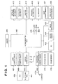
- Fig. 1 is a block diagram showing the circuit arrangement of a lens-interchangeable single-lens reflex digital camera which serves as an image capturing apparatus according to the first embodiment of the present invention
- Fig. 2 is a perspective view showing the outer appearance of the digital camera according to the first embodiment
- Fig. 3 is a longitudinal sectional view showing the internal structure of the digital camera according to the first embodiment
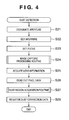
- Fig. 4 is a flowchart for explaining dust detection processing of the digital camera according to the first embodiment
- Fig. 5 is a view showing a data format example of dust correction data
- Fig. 6 is a flowchart for explaining details of a dust region acquisition routine in step S27 of Fig. 4;
- Fig. 7 is a view showing the process unit of dust region determination processing in step S62 of Fig. 6;
- Fig. 8 is a view showing the outline of dust region size calculation in step S63 of Fig. 6;
- Fig. 9 is a flowchart for explaining details of an image capture processing routine in step S24 of Fig. 4;
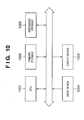
- Fig. 10 is a block diagram showing the schematic system configuration of an image processing apparatus
- Fig. 11 is a view showing an example of GUI of the image processing apparatus
- Fig. 12 is a flowchart for explaining details of dust removal processing
- Fig. 13 is a flowchart for explaining details of an interpolation routine
- Fig. 14 is a flowchart showing dust correction data conversion processing according to the third embodiment.
- Fig. 15 is a flowchart for explaining dust removal processing according to the third embodiment.
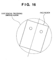
- Fig. 16 is a view showing a dust removal processing omission region according to the fourth embodiment.
- Fig. 17 is a flowchart for explaining an interpolation routine according to the fourth embodiment.
- a camera body detects dust and attaches dust correction data to image data
- an image processing apparatus outside the camera executes processing of removing the dust from the image data by using the dust correction data attached to the image data.
- Fig. 1 is a block diagram showing the circuit arrangement of a lens-interchangeable single-lens reflex digital camera which serves as an image capturing apparatus according to the first embodiment of the present invention.
- a microcomputer 402 controls the operation of the entire camera, including processing of image data output from an image sensor (CCD in this embodiment) 418 and display on an LCD monitor device 417.
- a switch (SW1) 405 is turned on in a half depressed state of a release button 114 (Fig. 2). When the switch (SW1) 405 is ON, the digital camera of this embodiment is ready for image capturing.
- a switch (SW2) 406 is turned on in a fully depressed state of the release button 114. When the switch (SW2) 406 is turned on, the digital camera of this embodiment starts image capturing.
- a lens control circuit 407 communicates with a photographing lens 200 (Fig. 3) and controls driving of the photographing lens 200 and driving of the aperture blades upon AF (Auto Focus).
- an external display control circuit 408 controls an external display device (OLC) 409 and a display device (not shown) in the viewfinder.
- a switch sense circuit 410 transmits, to the microcomputer 402, signals from a number of switches including an electronic dial 411 provided on the camera.
- An electronic flash brightness control circuit 412 is grounded via an X contact 412a and controls an external electronic flash.
- a distance measuring circuit 413 detects a defocus amount with respect to an object for AF.
- a photometry circuit 414 measures the brightness of an object.
- a shutter control circuit 415 controls a shutter to execute proper exposure for the image sensor.
- the LCD monitor device 417 and a backlight illumination device 416 constitute an image display device.
- a storage device 419 includes, for example, a hard disk drive or a semiconductor memory card detachable from the camera body.
- a dust position memory 427 to store a pixel position in the image sensor where an image error occurs due to dust also connects to the microcomputer 402.
- the pixel defect position memory 426 and dust position memory 427 preferably use a nonvolatile memory.
- the pixel defect position memory 426 and dust position memory 427 may store data by using different addresses of the same memory space.
- a nonvolatile memory 428 stores, for example, programs to be executed by the microcomputer 402.
- Fig. 2 is a perspective view showing the outer appearance of the digital camera according to this embodiment.
- Fig. 3 is a longitudinal sectional view of Fig. 2.
- a camera body 100 has, on the upper side, an eyepiece window 111 for viewfinder observation, an AE (Automatic Exposure) lock button 112, an AF distance measuring point selection button 113, and the release button 114 for the image capture operation.
- the electronic dial 411, image capture mode selection dial 117, and external display device 409 are also provided.
- the electronic dial 411 is a multifunction signal input device that inputs a numerical value to the camera or switches the image capture mode in cooperation with other operation buttons.
- the external display device 409 including a liquid display device displays image capture conditions such as the shutter speed, aperture value, and image capture mode and other information.
- the camera body 100 has, on its rear surface, the LCD monitor device 417 to display a captured image and various kinds of setting windows, a monitor switch 121 to turn on/off the LCD monitor device 417, a cursor switch 116, and a menu button 124.
- the cursor switch 116 has four buttons arranged on the upper, lower, left, and right sides and a SET button arranged at the center. The user uses the cursor switch 116 to instruct the camera to select or execute a menu item displayed on the LCD monitor device 417.
- the menu button 124 displays, on the LCD monitor device 417, a menu window to do various kinds of setting of the camera.
- the user presses the menu button 124 selects a desired mode by operating the upper, lower, left, and right buttons of the cursor switch 116, and presses the SET button while keeping the desired mode selected, thereby completing setting.
- the menu button 124 and cursor switch 116 are also used to set a dust mode (to be described later) and set a display mode and identification mark in the dust mode.
- the LCD monitor device 417 of this embodiment is of a transmission type so the user cannot visually recognize any image only by driving the LCD monitor device.
- the LCD monitor device 417 always requires the backlight illumination device 416 on its rear side, as shown in Fig. 3.
- the LCD monitor device 417 and backlight illumination device 416 constitute an image display device.
- the photographing lens 200 of the image capture optical system is detachably attached to the camera body 100 via a lens mount 202.
- reference numeral 201 denotes an image capture optical axis; and 203, a quick return mirror.
- the quick return mirror 203 arranged in the image capture optical path is movable between a position (position shown in Fig. 3 which will be referred to as an inclined position) to guide object light from the photographing lens 200 to the viewfinder optical system and a position (to be referred to as a retreat position) to retreat from the image capture optical path.
- an image of object light guided from the quick return mirror 203 to the viewfinder optical system is formed on a focusing screen 204.
- a condenser lens 205 improves the visibility of the viewfinder.
- a pentagonal roof prism 206 guides the object light that has passed through the focusing screen 204 and condenser lens 205 to an eyepiece 208 for viewfinder observation and a photometry sensor 207.
- a shutter includes a front curtain 209 and a rear curtain 210.
- the image sensor 418 serving as a solid-state image sensor arranged on the rear side is exposed for a necessary period of time.
- a captured image converted into an electrical signal for each pixel by the image sensor 418 is processed by the A/D converter 423 and image processing circuit 425 and recorded in the storage device 419 as image data.
- the image sensor 418 is held on a printed circuit board 211.
- Another printed circuit board i.e., a display board 215 is arranged on the rear side of the printed circuit board 211.
- the LCD monitor device 417 and backlight illumination device 416 are arranged on the opposite surface of the display board 215.
- the storage device 419 records image data.
- Reference numeral 217 denotes a battery (portable power supply).
- the storage device 419 and battery 217 are detachable from the camera body.
- Fig. 4 is a flowchart for explaining dust detection processing (processing of detecting a pixel position where an image error occurs due to dust) of the digital camera according to this embodiment. This processing is done by causing the microcomputer 402 to execute a dust detection processing program stored in the memory 428.
- Dust detection processing is executed by capturing a dust detection image.
- the camera is installed while keeping the image capture optical axis 201 of the photographing lens 200 directed to a surface with a uniform color such as the exit surface of a surface source or a white wall, thereby preparing for dust detection.
- a light unit (a small point source device attached in place of a lens) for dust detection is attached to the lens mount 202 to prepare for dust detection.
- the light unit can employ, for example, a white LED as its light source and preferably adjusts the light-emitting surface size in correspondence with a predetermined aperture value (for example, F64 in this embodiment).
- the dust detection image is an image having a uniform color, as described above.
- the microcomputer 402 sets the aperture first.
- the imaging state of dust near the image sensor changes depending on the aperture value of the lens.
- the position of dust changes depending on the lens pupil position.
- dust correction data must hold the aperture value and the lens pupil position upon detection in addition to the position and size of dust.
- the dust correction data need not always hold the aperture value.
- the pupil position indicates the distance from the image sensing plane (focal plane) of the exit pupil.
- F16 is designated (step S21).
- the microcomputer 402 causes the lens control circuit 407 to control the aperture blades of the photographing lens 200 to set the aperture to the aperture value designated in step S21 (step 322). In addition, the microcomputer 402 sets the focus position to the infinite distance (step S23).
- step S24 image capturing in the dust detection mode is executed (step S24).
- the image capture processing routine executed in step S24 will be described later in detail with reference to Fig. 9. Obtained image data is stored in the image buffer memory 424.
- step S25 When image capturing ends, the aperture value and lens pupil position upon image capturing are acquired (step S25). Data corresponding to each pixel of the captured image stored in the image buffer memory 424 is loaded to the image processing circuit 425 (step S26).
- the image processing circuit 425 executes processing shown in Fig. 6 to acquire the positions and size of pixels with dust (step S27).
- the positions and size of the pixels with dust acquired in step S27 and the aperture value and lens pupil position information acquired in step S25 are registered in the dust position memory 427 (step S28).
- no lens information can be acquired. If no lens information is acquired, it is determined that the light unit was used. In this case, predetermined lens pupil position information and a reduced aperture value calculated from the light source diameter of the light unit are registered.
- step S28 the position of each defective pixel (pixel defect) in manufacturing, which is recorded in the pixel defect position memory in advance, is compared with the position of each readout pixel data to confirm whether a pixel defect is present.
- the position of only a region determined to have a defect other than a pixel defect is registered in the dust position memory 427.
- Fig. 5 is a view showing a data format example of dust correction data stored in the dust position memory 427. As shown in Fig. 5, lens information and information representing the position and size of dust upon capturing a detection image are stored as dust correction data. The dust correction data is added to an image together with the information of image data upon acquisition and used by dust removal processing to be described later.
- an actual aperture value (F-number) and lens pupil position upon capturing a detection image are stored as lens information upon capturing a detection image.
- the number (integral value) of detected dust regions is stored in the storage area.
- individual parameters of each dust region are stored repeatedly in correspondence with the number of dust regions.
- the dust region parameters include a set of three numerical values: the radius (for example, 2 bytes) of dust, the x-coordinate (for example, 2 bytes) of the center of the effective image region, and the y-coordinate (for example, 2 bytes) of the center.
- step S27 sorts the dust regions in descending order of visibility.
- readout image data is rasterized on the memory, and each predetermined block is processed.
- the image data is segmented into blocks to cope with limb darkening caused by the lens or sensor characteristic.
- Limb darkening is a phenomenon to decrease the brightness of the peripheral portion of a lens as compared to the central portion. Limb darkening decreases in the stopped-down-aperture state, as is known. Even in the stopped-down-aperture state, however, it is impossible for some lenses to accurately detect dust at the peripheral portion if the dust position is determined on the basis of a threshold value predetermined for a captured image. To prevent this, the influence of limb darkening is reduced by segmenting image data into blocks.
- Simple block segmentation poses such a problem that if the threshold value changes between blocks, the dust detection position across the blocks becomes inaccurate. To prevent this, the blocks are overlapped, and a pixel determined to be dust in any one of blocks included in the overlap region is handled as a dust region.
- Dust region determination in a block is done in accordance the procedure shown in Fig. 6.
- a maximum brightness Lmax and an average brightness Lave in the block are calculated.
- a pixel having a brightness value smaller than the threshold value is regarded as a dust pixel (step S61).
- a maximum value Xmax and minimum value Xmin of the horizontal coordinates of the pixels included in the dust region and a maximum value Ymax and minimum value Ymin of the vertical coordinates are obtained.
- a radius ri representing the size of the dust region di is calculated by the following equation (step S63).
- ri ⁇ ⁇ Xmax - Xmin / 2 2 ⁇ Ymax - Ymin / 2 2 Fig. 8 shows the relationship between Xmax, Ymax, Xmin, Ymin, and ri.
- step S64 the average brightness value of each dust region is calculated.
- the dust correction data size is restricted by, for example, the capacity of the dust position memory 427.
- the pieces of dust position information are sorted on the basis of the sizes or average brightness values of the dust regions (step S66). In this case, sorting is done in descending order of ri. If ri is the same, sorting is done in ascending order of average brightness values. This allows to preferentially register noticeable dust in the dust correction data. Let Di be a sorted dust region, and Ri be the radius of the dust region Di.
- a dust region larger than a predetermined size may be excluded from the sorting target and located at the end of the sorted dust region list.
- a large dust region may degrade the image quality by interpolation processing later and is therefore preferably handled as a correction target with the lowest priority.
- step S24 of Fig. 4 will be described next with reference to the flowchart in Fig. 9. This processing is done by causing the microcomputer 402 to execute an image capture processing program stored in the memory 428.
- the microcomputer 402 actuates the quick return mirror 203 shown in Fig. 3 to do so-called mirror up in step S201 and make the quick return mirror 203 retreat from the image capture optical path.
- step S202 the image sensor starts storing charges.
- step S203 the rear curtain 210 and front curtain 209 of the shutter shown in Fig. 3 are opened to execute exposure.
- step S204 the image sensor ends charge storage.
- step S205 the image signal is read out from the image sensor and processed by the A/D converter 423 and image processing circuit 425. The resultant image data is primarily stored in the image buffer memory 424.
- step S206 When readout of all image signals from the image sensor is complete in step S206, the quick return mirror 203 is moved down in step S207 and returned to the inclined position, thereby ending the series of image capture operations.
- step S208 it is determined whether the operation is normal image capturing or dust detection image capturing.
- the process advances to step S209 to record, in the storage device 419, the dust correction data shown in Fig. 5 together with the camera setting values upon image capturing in association with the image data.
- data association can be attained by additionally writing the dust correction data in, for example, an Exif region serving as the header region of an image file where the camera setting values upon image capturing are recorded.
- Data association may also be attained by recording the dust correction data as an independent file and recording, in the image data, only link information to the dust correction data file. However, if the image file and dust correction data file are separately recorded, the link relationship may be lost by image file moving.
- the dust correction data is preferably held integrally with the image data.
- Dust removal processing is done not in the camera body but on a separately prepared image processing apparatus.
- Fig. 10 is a block diagram showing the schematic system configuration of the image processing apparatus.
- a CPU 1001 controls the operation of the whole system and executes, for example, a program stored in a primary storage unit 1002.
- the primary storage unit 1002 mainly includes a memory, which reads out a program from a secondary storage unit 1003 and stores it.
- the secondary storage unit 1003 corresponds to, for example, a hard disk.
- the capacity of the primary storage unit is generally smaller than that of the secondary storage unit.
- the secondary storage unit stores programs and data with a size beyond the capacity of the primary storage unit.
- the secondary storage unit also stores data that requires long time storage.
- the secondary storage unit 1003 stores a program. To execute the program, the primary storage unit 1002 reads it out, and the CPU 1001 executes processing.
- An input device 1004 corresponds to, for example, not only a mouse and keyboard used for system control but also a card reader, scanner, and film scanner necessary for inputting image data.
- Examples of an output device 1005 are a monitor and a printer. This apparatus can take various forms except that described above, though a description thereof will be omitted because it is not necessary for understanding of the present invention.
- the image processing apparatus has an operating system capable of executing a plurality of programs in parallel.
- the operator can operate a program running on this apparatus by using GUI.
- Fig. 11 is a view showing an example of GUI (Graphical User Interface) of an image editing program in the image processing apparatus.
- a window has a close button 1100 and a title bar 1101. The program ends upon clicking on the close button.
- a file is dragged and dropped in an image display region 1102 to designate a correction target image.
- the correction target image is determined, the file name is displayed on the title bar 1101, and the target image is Fit-displayed in the image display region 1102.
- Dust removal processing (to be described later) is executed by clicking on an execute button 1103 so that a processed image is displayed in the image display region 1102.
- steps of the dust removal processing (to be described later) are executed.
- the processing ends for all dust regions the processed image is displayed in the image display region 1102.
- the processed image is stored by clicking on a save button 1105.
- Fig. 12 shows the procedure of dust removal processing by the image processing apparatus.
- the image processing apparatus reads out normal captured image data with dust correction data from the digital camera or the storage device 419 detached from the digital camera and stores the data in the primary storage unit 1002 or secondary storage unit 1003 (step S90).
- the dust correction data added to the captured image in step S209 is extracted from the normal captured image data (dust removal processing target) (step S91).
- Ri is the size of dust at the coordinates Di calculated in step S65 of Fig. 6.
- an aperture value f2 and a lens pupil position L2 upon normal image capturing are acquired.
- Di is converted by the following expression, where d is the distance from the image center to the coordinates Di, H is the distance between the dust and the surface of the image sensor 418.
- the unit is "pixel", and "+3" for Ri' is the margin amount. Ri' is doubled because a region except the dust region is necessary for detecting the dust region by using the average brightness.
- step S95 dust in the region represented by the coordinates Di' and radius Ri' is detected, and interpolation processing is applied as needed. The interpolation processing will be described later in detail.
- step S96 it is determined whether dust removal processing is applied to all coordinates. If the processing is complete for all coordinates, the processing ends. Otherwise, the process returns to step S95.
- Fig. 13 is a flowchart showing the procedure of the interpolation routine.
- dust region determination is done.
- a dust region is a region that satisfies all of the following conditions.
- T ⁇ 2 Yave ⁇ 0.6 + Ymax ⁇ 0.4
- Yave is the average brightness
- Ymax is the maximum brightness of pixels included in a region represented by the central coordinates Di' and radius Ri' (Di' and Ri' obtained by equation (1)) calculated in step S94 of Fig. 12.
- 11 is three pixels, and 12 is 30 pixels. This allows to handle only an isolated small region as a dust region. If it is impossible to accurately acquire the lens pupil position, the condition (4) may appropriately be changed. For example, a region of interest which includes coordinates within the range of ⁇ 3 pixels in the X and Y directions from the coordinates Di may be determined as a dust region.
- step S1203 If such a region exists in step S1202, the process advances to step S1203 to execute dust region interpolation. If no region exists, the processing ends.
- the dust region interpolation processing in step S1203 is executed by a known defective region interpolation method.
- An example of the known defective region interpolation method is pattern replacement disclosed in Japanese Patent Laid-Open No. 2001-223894 .
- the method of Japanese Patent Laid-Open No. 2001-223894 specifies a defective region by using infrared light.
- the dust region detected in step S1201 is handled as a defective region, and pattern replacement is executed to interpolate the dust region by normal pixels in the neighborhood. For a pixel that is not obtained by pattern replacement, p normal pixels are selected in ascending order of distance from the interpolation target pixel in the image data after pattern replacement, and interpolation is executed by using the average color of the pixels.
- dust correction data is attached to image data, the user need not be aware of the correspondence between dust correction image data and captured image data. Since the dust correction data containing the position, size, and conversion data (aperture value and distance information of the lens pupil position) is compact, the captured image data size can be prevented from excessively increasing. It is also possible to greatly reduce the detection error probability by interpolating only a region including pixels designated by the dust detection processing.
- the separately prepared image processing apparatus executes dust removal processing.
- a method of causing the camera body to execute dust removal processing will be described.
- a digital camera according to the second embodiment has the same arrangement as in the first embodiment, and a description thereof will be omitted. Only operations different from the first embodiment will be described.
- the dust removal routine of the digital camera executes the same processing as in the flowchart of Fig. 12. This processing is done by causing a microcomputer 402 to execute a dust removal processing program stored in a memory 428.
- the microcomputer 402 loads, to an image processing circuit 425, data corresponding to each pixel of a captured image stored in an image buffer memory 424.
- the image processing circuit 425 executes the processing shown in Fig. 12 to interpolate dust pixels.
- the interpolation processing result is recorded in a storage device 419 as a new image file.
- the user can properly remove dust without being aware of the correspondence between dust detection image data and normal captured image data. It is also possible to attach data without largely increasing the image data file size even in embedding dust correction data in an image.
- a separately prepared image processing apparatus converts dust correction data attached by the digital camera body by processing it in accordance with the procedure shown in Fig. 12 and then executes dust removal processing.
- the digital camera body executes conversion, the separately prepared image processing apparatus only needs to execute dust removal processing at designated coordinates.
- step S209 of the image capture processing routine shown in Fig. 9 dust correction data conversion processing is executed (to be described later in detail).
- the dust correction data is stored in a storage device 419 in association with image data. Since the dust correction data is already converted, it is unnecessary to store the F-number and lens pupil position upon image capturing in the converted dust correction data stored in association with the image data.
- Fig. 14 is a flowchart showing the procedure of dust correction data conversion processing.
- step S141 dust correction data stored in a dust position memory 427 is acquired.
- the process advances to step S142 to acquire, from the dust correction data acquired in step S141, the aperture value and lens pupil position (parameters upon dust acquisition) upon capturing a dust detection image.
- step S143 the aperture value and lens pupil position (parameters upon image capturing) upon normal image capturing are acquired.
- step S144 the dust correction data is converted on the basis of the parameters upon dust acquisition and the parameters upon image capturing.
- the process in steps S142 to S144 is the same as in steps S92 to S94 of Fig. 12, and a detailed description thereof will be omitted.
- the dust correction data added to the captured image in step S209 is extracted from the normal captured image data (dust removal processing target) (step S151).
- step S153 dust in the region represented by the coordinates Di and radius Ri is detected, and interpolation processing is applied as needed. Detailed of the interpolation processing are the same as in the first embodiment.
- step S154 it is determined whether dust removal processing is applied to all coordinates. If the processing is complete for all coordinates, the processing ends. Otherwise, the process returns to step S153.
- an eye may erroneously be determined as a dust region and subjected to interpolation processing.
- the position of a face region in a captured image is specified by executing face detection processing, and the region is excluded from the interpolation processing target. This reduces the possibility of interpolation errors for face parts such as an eye and nose.
- This method is excellent in the following point. Even when a non-face region is erroneously detected as a face region by face detection processing, this has no adverse effect on the original image because the erroneously detected region is excluded from the interpolation processing target.
- Face detection processing is done by a known technique.
- a method disclosed in, for example, Japanese Patent Laid-Open No. 2004-62651 is used.
- a rectangle shown in Fig. 3(b) of Japanese Patent Laid-Open No. 2004-62651 can be acquired as a detection result.
- a circle circumscribing a detected rectangle is regarded as a face region, i.e., a dust removal processing omission region, as shown in Fig. 16.
- Either the image capturing apparatus side or the external image processing apparatus side can detect the dust removal processing omission region.
- the image capturing apparatus side detects the dust removal processing omission region
- the information of the dust removal processing omission region (face region), the camera setting values upon image capturing, and the dust correction data are stored in a storage device 419 in association with image data.
- step S1701 a defective region is determined.
- the processing contents are the same as in step S1201 of Fig. 13.
- step S1702 it is determined whether a defective region exists. If no defective region exists, the processing ends. If a defective region exists, the process advances to step S1703.
- steps S1703 to S1706 it is determined whether each target defective region detected in step S1701 overlaps the dust removal processing omission region detected by face detection processing. If a target defective region does not overlap all the dust removal processing omission regions, the process advances to step S1707 to interpolate the target defective region.
- Defective region interpolation processing is the same as in step S1202 of Fig. 13, and a description thereof will be omitted.
- step S1708 it is determined whether the processing in step S1703 to S1707 ends for all defective regions detected in step S1701. If the processing ends for all defective regions, the interpolation processing routine ends. If an unprocessed defective region remains, the process returns to step S1703 to repeat steps S1703 to S1708.
- Whether a defective region overlaps the dust removal processing omission region is determined in the following way.
- the above-described processing serves to prevent any inappropriate processing result for a region that may be subjected to dust removal processing at a high probability.
- a storage medium (or recording medium) which records software program codes to implement the functions of the above-described embodiments is supplied to a system or apparatus.
- the computer or CPU or MPU
- the computer or CPU or MPU
- the program codes read out from the storage medium themselves implement the functions of the above-described embodiments.
- the functions of the above-described embodiments are implemented not only by causing the computer to execute the readout program codes.
- the operating system (OS) running on the computer wholly or partially executes actual processing on the basis of the instructions of the program codes, thereby implementing the functions of the above-described embodiments.
- the program codes read out from the storage medium are written in the memory of a function expansion card inserted to the computer or a function expansion unit connected to the computer.
- the CPU of the function expansion card or function expansion unit wholly or partially executes actual processing on the basis of the instructions of the program codes, thereby implementing the functions of the above-described embodiments.
- the storage medium may stores program codes corresponding to the above-described procedures.
Landscapes
- Engineering & Computer Science (AREA)
- Multimedia (AREA)
- Signal Processing (AREA)
- Studio Devices (AREA)
- Color Television Image Signal Generators (AREA)
- Blocking Light For Cameras (AREA)
Applications Claiming Priority (2)
| Application Number | Priority Date | Filing Date | Title |
|---|---|---|---|
| JP2006005396 | 2006-01-12 | ||
| JP2006211379A JP2007215151A (ja) | 2006-01-12 | 2006-08-02 | 撮像装置及びその制御方法及びプログラム |
Publications (2)
| Publication Number | Publication Date |
|---|---|
| EP1809019A2 true EP1809019A2 (de) | 2007-07-18 |
| EP1809019A3 EP1809019A3 (de) | 2011-09-28 |
Family
ID=37944111
Family Applications (1)
| Application Number | Title | Priority Date | Filing Date |
|---|---|---|---|
| EP07100433A Withdrawn EP1809019A3 (de) | 2006-01-12 | 2007-01-11 | Bildaufnahmevorrichtung, Steuerverfahren und Programm |
Country Status (5)
| Country | Link |
|---|---|
| US (1) | US8711241B2 (de) |
| EP (1) | EP1809019A3 (de) |
| JP (1) | JP2007215151A (de) |
| KR (1) | KR100815512B1 (de) |
| CN (1) | CN101001318B (de) |
Families Citing this family (35)
| Publication number | Priority date | Publication date | Assignee | Title |
|---|---|---|---|---|
| JP4644283B2 (ja) * | 2006-06-08 | 2011-03-02 | 富士通株式会社 | 汚れ検出方式 |
| JP4771539B2 (ja) * | 2006-07-26 | 2011-09-14 | キヤノン株式会社 | 画像処理装置及びその制御方法及びプログラム |
| JP5046769B2 (ja) * | 2007-07-24 | 2012-10-10 | キヤノン株式会社 | 撮像装置及びその制御方法及びプログラム |
| JP4989385B2 (ja) * | 2007-09-12 | 2012-08-01 | キヤノン株式会社 | 撮像装置及びその制御方法及びプログラム |
| JP4960852B2 (ja) * | 2007-12-19 | 2012-06-27 | キヤノン株式会社 | 画像処理装置及びその制御方法及びレンズ交換式一眼レフデジタルカメラ及びプログラム |
| JP4951540B2 (ja) * | 2008-01-23 | 2012-06-13 | ペンタックスリコーイメージング株式会社 | ダスト検出装置およびデジタルカメラ |
| JP5014262B2 (ja) * | 2008-06-05 | 2012-08-29 | キヤノン株式会社 | 撮像装置及びその制御方法及びプログラム |
| US8593537B2 (en) * | 2008-06-05 | 2013-11-26 | Canon Kabushiki Kaisha | Image sensing apparatus, control method thereof, and program for suppressing image deterioration caused by foreign substance |
| JP5094665B2 (ja) * | 2008-09-26 | 2012-12-12 | キヤノン株式会社 | 撮像装置及びその制御方法及びプログラム |
| JP5228888B2 (ja) * | 2008-12-24 | 2013-07-03 | 株式会社ニコン | 画像データ処理装置 |
| JP5822479B2 (ja) * | 2011-02-15 | 2015-11-24 | キヤノン株式会社 | 撮像装置 |
| JP2014026049A (ja) | 2012-07-25 | 2014-02-06 | Sony Corp | クリーニング装置とクリーニング方法および撮像装置 |
| MX361919B (es) * | 2012-07-27 | 2018-12-19 | Nissan Motor | Dispositivo de detección de gotas de agua y dispositivo de detección de objetos tridimensionales usando un dispositivo de detección de gotas de agua. |
| JP2014150362A (ja) * | 2013-01-31 | 2014-08-21 | Canon Inc | 撮像装置 |
| US9424629B2 (en) * | 2013-02-01 | 2016-08-23 | Canon Kabushiki Kaisha | Image pickup apparatus, image processing apparatus, image processing method, and non-transitory computer-readable storage medium |
| CN103546740B (zh) * | 2013-09-03 | 2015-11-25 | 小米科技有限责任公司 | 一种检测摄像头的方法、装置及终端设备 |
| CN104463827B (zh) * | 2013-09-17 | 2019-02-05 | 联想(北京)有限公司 | 一种图像采集模块的自动检测方法及相应的电子设备 |
| DE102013019138A1 (de) * | 2013-11-12 | 2015-05-13 | Application Solutions (Electronics and Vision) Ltd. | Verfahren zum Erkennen eines verdeckten Zustands einer Kamera, Kamerasystem und Kraftfahrzeug |
| EP2899692B1 (de) * | 2014-01-28 | 2019-09-04 | Honda Research Institute Europe GmbH | Verfahren, System, Bildgebungsvorrichtung, bewegliche Vorrichtung und Programmprodukt zum Erfassen von statischen Elementen in Video- und Bildquellen |
| US10438631B2 (en) | 2014-02-05 | 2019-10-08 | Snap Inc. | Method for real-time video processing involving retouching of an object in the video |
| CN104333705B (zh) * | 2014-11-28 | 2017-07-07 | 广东欧珀移动通信有限公司 | 一种图像增强方法及装置 |
| US10116901B2 (en) | 2015-03-18 | 2018-10-30 | Avatar Merger Sub II, LLC | Background modification in video conferencing |
| US9948842B2 (en) | 2015-06-26 | 2018-04-17 | Kodak Alaris Inc. | Camera subassembly dust and defect detection system and method |
| CN106973291A (zh) * | 2017-06-01 | 2017-07-21 | 信利光电股份有限公司 | 一种摄像模组、电子设备、污点修复方法及系统 |
| JP6903023B2 (ja) | 2018-03-12 | 2021-07-14 | 株式会社Pfu | 画像読取装置、画像処理システム及び異物検出方法 |
| JP6873074B2 (ja) | 2018-03-12 | 2021-05-19 | 株式会社Pfu | 画像処理装置、制御方法及び制御プログラム |
| JP6895914B2 (ja) * | 2018-03-12 | 2021-06-30 | 株式会社Pfu | 画像読取装置、画像処理システム、制御方法及び制御プログラム |
| JP6917926B2 (ja) | 2018-03-12 | 2021-08-11 | 株式会社Pfu | 画像処理装置、制御方法及び制御プログラム |
| CN108780050B (zh) * | 2018-03-29 | 2020-10-09 | 深圳达闼科技控股有限公司 | 检测镜头的方法及装置、电子设备和计算机可读存储介质 |
| US11089199B2 (en) | 2018-06-21 | 2021-08-10 | Canon Kabushiki Kaisha | Accessory device, imaging apparatus, and methods for controlling the same |
| CN108535901A (zh) * | 2018-06-21 | 2018-09-14 | 任志桂 | 一种tft液晶玻璃缺陷自动检测装置 |
| CN109640075B (zh) * | 2018-12-24 | 2020-10-09 | 维沃移动通信有限公司 | 一种摄像检测装置、方法及移动终端 |
| US11340845B1 (en) | 2021-03-12 | 2022-05-24 | Hewlett-Packard Development Company, L.P. | Determination of predicted failure modes based on properties of dust in printing devices |
| CN113011316B (zh) * | 2021-03-16 | 2023-05-30 | 北京百度网讯科技有限公司 | 一种镜头状态的检测方法、装置、电子设备和介质 |
| CN113256600B (zh) * | 2021-06-10 | 2021-11-19 | 浙江华睿科技股份有限公司 | 基于人工智能的相机灰尘检测方法、装置及电子设备 |
Citations (2)
| Publication number | Priority date | Publication date | Assignee | Title |
|---|---|---|---|---|
| EP1394740A2 (de) * | 2002-08-30 | 2004-03-03 | Konica Corporation | Bildverarbeitung abhängig von einem Bildaufnahmegerätecharakteristikum |
| US20050068452A1 (en) | 2003-09-30 | 2005-03-31 | Eran Steinberg | Digital camera with built-in lens calibration table |
Family Cites Families (14)
| Publication number | Priority date | Publication date | Assignee | Title |
|---|---|---|---|---|
| JP2001218115A (ja) * | 2000-01-31 | 2001-08-10 | Sony Corp | 固体撮像装置及びその欠陥画素記録方法 |
| JP2001223894A (ja) | 2000-02-14 | 2001-08-17 | Canon Inc | 画像処理装置、方法および記憶媒体 |
| JP4167401B2 (ja) * | 2001-01-12 | 2008-10-15 | 富士フイルム株式会社 | ディジタル・カメラおよびその動作制御方法 |
| WO2003049029A1 (en) | 2001-12-04 | 2003-06-12 | Pony Industry Co., Ltd. | Image processing method and image processor |
| JP2003295281A (ja) * | 2002-04-03 | 2003-10-15 | Canon Inc | 撮像装置及び動作処理方法及びプログラム及び記憶媒体 |
| JP2004062651A (ja) | 2002-07-30 | 2004-02-26 | Canon Inc | 画像処理装置、画像処理方法、その記録媒体およびそのプログラム |
| GB2395781A (en) * | 2002-11-29 | 2004-06-02 | Sony Uk Ltd | Face detection |
| JP2004193729A (ja) * | 2002-12-09 | 2004-07-08 | Fuji Photo Film Co Ltd | 画像記録済み記録媒体、画像ファイルの記録方法及びデジタルカメラ |
| JP4466015B2 (ja) | 2002-12-27 | 2010-05-26 | 株式会社ニコン | 画像処理装置および画像処理プログラム |
| CN101778203B (zh) * | 2002-12-27 | 2012-06-06 | 株式会社尼康 | 图像处理装置 |
| US7295233B2 (en) * | 2003-09-30 | 2007-11-13 | Fotonation Vision Limited | Detection and removal of blemishes in digital images utilizing original images of defocused scenes |
| JP4480147B2 (ja) | 2004-09-13 | 2010-06-16 | キヤノン株式会社 | 撮像装置およびその制御方法 |
| KR100619306B1 (ko) | 2004-09-24 | 2006-09-12 | 엘지전자 주식회사 | 디지털 이미징 장치의 불량화소 추출 방법 |
| JP4678860B2 (ja) * | 2006-01-24 | 2011-04-27 | キヤノン株式会社 | 撮像装置及びその制御方法とプログラム |
-
2006
- 2006-08-02 JP JP2006211379A patent/JP2007215151A/ja not_active Withdrawn
-
2007
- 2007-01-11 EP EP07100433A patent/EP1809019A3/de not_active Withdrawn
- 2007-01-11 US US11/622,087 patent/US8711241B2/en not_active Expired - Fee Related
- 2007-01-12 CN CN2007100005791A patent/CN101001318B/zh not_active Expired - Fee Related
- 2007-01-12 KR KR1020070003554A patent/KR100815512B1/ko not_active Expired - Fee Related
Patent Citations (2)
| Publication number | Priority date | Publication date | Assignee | Title |
|---|---|---|---|---|
| EP1394740A2 (de) * | 2002-08-30 | 2004-03-03 | Konica Corporation | Bildverarbeitung abhängig von einem Bildaufnahmegerätecharakteristikum |
| US20050068452A1 (en) | 2003-09-30 | 2005-03-31 | Eran Steinberg | Digital camera with built-in lens calibration table |
Also Published As
| Publication number | Publication date |
|---|---|
| EP1809019A3 (de) | 2011-09-28 |
| KR100815512B1 (ko) | 2008-03-20 |
| CN101001318A (zh) | 2007-07-18 |
| CN101001318B (zh) | 2013-04-24 |
| US20070159551A1 (en) | 2007-07-12 |
| JP2007215151A (ja) | 2007-08-23 |
| KR20070075346A (ko) | 2007-07-18 |
| US8711241B2 (en) | 2014-04-29 |
Similar Documents
| Publication | Publication Date | Title |
|---|---|---|
| EP1809019A2 (de) | Bildaufnahmevorrichtung, Steuerverfahren und Programm | |
| US8089536B2 (en) | Image processing apparatus, image processing method, and program | |
| CN101282418B (zh) | 图像处理设备及其控制方法 | |
| JP4799462B2 (ja) | 画像処理装置及びその制御方法及びプログラム及び記憶媒体及び撮像装置 | |
| US7619666B2 (en) | Image processing apparatus, control method therefor, and program correcting image data based on foreign substance information and inhibiting such correction | |
| US8238690B2 (en) | Image processing apparatus, control method therefor, and program | |
| US7990419B2 (en) | Image processing apparatus, method, and program storing a correction or modification log | |
| US8576306B2 (en) | Image sensing apparatus, image processing apparatus, control method, and computer-readable medium | |
| JP4960852B2 (ja) | 画像処理装置及びその制御方法及びレンズ交換式一眼レフデジタルカメラ及びプログラム | |
| JP2010098698A (ja) | 撮像装置及びその制御方法及びプログラム | |
| JP4827778B2 (ja) | 画像処理装置及び画像処理方法及びプログラム及び記憶媒体 | |
| JP2008244868A (ja) | 撮像装置及びその制御方法及びプログラム及び記憶媒体 | |
| JP5094571B2 (ja) | 撮像装置及びその制御方法及びプログラム |
Legal Events
| Date | Code | Title | Description |
|---|---|---|---|
| PUAI | Public reference made under article 153(3) epc to a published international application that has entered the european phase |
Free format text: ORIGINAL CODE: 0009012 |
|
| AK | Designated contracting states |
Kind code of ref document: A2 Designated state(s): AT BE BG CH CY CZ DE DK EE ES FI FR GB GR HU IE IS IT LI LT LU LV MC NL PL PT RO SE SI SK TR |
|
| AX | Request for extension of the european patent |
Extension state: AL BA HR MK YU |
|
| RIC1 | Information provided on ipc code assigned before grant |
Ipc: H04N 1/62 20060101ALI20110228BHEP Ipc: G06T 5/00 20060101ALI20110228BHEP Ipc: H04N 5/217 20110101AFI20070425BHEP |
|
| PUAL | Search report despatched |
Free format text: ORIGINAL CODE: 0009013 |
|
| AK | Designated contracting states |
Kind code of ref document: A3 Designated state(s): AT BE BG CH CY CZ DE DK EE ES FI FR GB GR HU IE IS IT LI LT LU LV MC NL PL PT RO SE SI SK TR |
|
| AX | Request for extension of the european patent |
Extension state: AL BA HR MK RS |
|
| RIC1 | Information provided on ipc code assigned before grant |
Ipc: H04N 1/409 20060101ALI20110825BHEP Ipc: H04N 5/335 20110101ALI20110825BHEP Ipc: H04N 1/62 20060101ALI20110825BHEP Ipc: G06T 5/00 20060101ALI20110825BHEP Ipc: H04N 5/217 20110101AFI20110825BHEP |
|
| 17P | Request for examination filed |
Effective date: 20120328 |
|
| AKX | Designation fees paid |
Designated state(s): DE FR GB |
|
| 17Q | First examination report despatched |
Effective date: 20120611 |
|
| STAA | Information on the status of an ep patent application or granted ep patent |
Free format text: STATUS: THE APPLICATION HAS BEEN WITHDRAWN |
|
| 18W | Application withdrawn |
Effective date: 20141125 |