EP1804675B1 - Capteurs combines ameliores, fil-guide - Google Patents
Capteurs combines ameliores, fil-guide Download PDFInfo
- Publication number
- EP1804675B1 EP1804675B1 EP05800066A EP05800066A EP1804675B1 EP 1804675 B1 EP1804675 B1 EP 1804675B1 EP 05800066 A EP05800066 A EP 05800066A EP 05800066 A EP05800066 A EP 05800066A EP 1804675 B1 EP1804675 B1 EP 1804675B1
- Authority
- EP
- European Patent Office
- Prior art keywords
- sensor
- housing
- tip
- guidewire
- pressure
- Prior art date
- Legal status (The legal status is an assumption and is not a legal conclusion. Google has not performed a legal analysis and makes no representation as to the accuracy of the status listed.)
- Active
Links
- 238000002604 ultrasonography Methods 0.000 claims description 35
- 239000013078 crystal Substances 0.000 claims description 5
- 230000008878 coupling Effects 0.000 claims description 4
- 238000010168 coupling process Methods 0.000 claims description 4
- 238000005859 coupling reaction Methods 0.000 claims description 4
- 239000004065 semiconductor Substances 0.000 claims description 2
- 239000004020 conductor Substances 0.000 description 48
- 238000005259 measurement Methods 0.000 description 21
- 239000004642 Polyimide Substances 0.000 description 20
- 229920001721 polyimide Polymers 0.000 description 20
- 238000013461 design Methods 0.000 description 18
- 238000000034 method Methods 0.000 description 14
- 239000000463 material Substances 0.000 description 13
- 230000035479 physiological effects, processes and functions Effects 0.000 description 10
- 238000009530 blood pressure measurement Methods 0.000 description 9
- 208000031481 Pathologic Constriction Diseases 0.000 description 7
- 239000002131 composite material Substances 0.000 description 7
- 230000008569 process Effects 0.000 description 7
- 230000036262 stenosis Effects 0.000 description 7
- 208000037804 stenosis Diseases 0.000 description 7
- 229910001220 stainless steel Inorganic materials 0.000 description 6
- 239000010935 stainless steel Substances 0.000 description 6
- 239000004593 Epoxy Substances 0.000 description 5
- 239000000853 adhesive Substances 0.000 description 4
- 230000001070 adhesive effect Effects 0.000 description 4
- BASFCYQUMIYNBI-UHFFFAOYSA-N platinum Chemical compound [Pt] BASFCYQUMIYNBI-UHFFFAOYSA-N 0.000 description 4
- 230000008901 benefit Effects 0.000 description 3
- 210000004351 coronary vessel Anatomy 0.000 description 3
- 238000005520 cutting process Methods 0.000 description 3
- 230000002441 reversible effect Effects 0.000 description 3
- 238000000926 separation method Methods 0.000 description 3
- 238000009987 spinning Methods 0.000 description 3
- 229910000831 Steel Inorganic materials 0.000 description 2
- OIRDTQYFTABQOQ-KQYNXXCUSA-N adenosine Chemical compound C1=NC=2C(N)=NC=NC=2N1[C@@H]1O[C@H](CO)[C@@H](O)[C@H]1O OIRDTQYFTABQOQ-KQYNXXCUSA-N 0.000 description 2
- 230000017531 blood circulation Effects 0.000 description 2
- 230000036772 blood pressure Effects 0.000 description 2
- 230000000694 effects Effects 0.000 description 2
- 238000005530 etching Methods 0.000 description 2
- 230000000544 hyperemic effect Effects 0.000 description 2
- 208000014674 injury Diseases 0.000 description 2
- 239000011810 insulating material Substances 0.000 description 2
- 230000000873 masking effect Effects 0.000 description 2
- 230000013011 mating Effects 0.000 description 2
- 239000002184 metal Substances 0.000 description 2
- 229910052751 metal Inorganic materials 0.000 description 2
- 238000001465 metallisation Methods 0.000 description 2
- 238000012986 modification Methods 0.000 description 2
- 230000004048 modification Effects 0.000 description 2
- 229910052697 platinum Inorganic materials 0.000 description 2
- 230000002829 reductive effect Effects 0.000 description 2
- 230000000284 resting effect Effects 0.000 description 2
- 239000010959 steel Substances 0.000 description 2
- 230000007704 transition Effects 0.000 description 2
- 230000008733 trauma Effects 0.000 description 2
- 208000037260 Atherosclerotic Plaque Diseases 0.000 description 1
- 239000002126 C01EB10 - Adenosine Substances 0.000 description 1
- RYGMFSIKBFXOCR-UHFFFAOYSA-N Copper Chemical compound [Cu] RYGMFSIKBFXOCR-UHFFFAOYSA-N 0.000 description 1
- 241000282414 Homo sapiens Species 0.000 description 1
- 239000004696 Poly ether ether ketone Substances 0.000 description 1
- 229920002614 Polyether block amide Polymers 0.000 description 1
- 229960005305 adenosine Drugs 0.000 description 1
- 238000002399 angioplasty Methods 0.000 description 1
- 238000013459 approach Methods 0.000 description 1
- 230000003143 atherosclerotic effect Effects 0.000 description 1
- 238000005452 bending Methods 0.000 description 1
- JUPQTSLXMOCDHR-UHFFFAOYSA-N benzene-1,4-diol;bis(4-fluorophenyl)methanone Chemical compound OC1=CC=C(O)C=C1.C1=CC(F)=CC=C1C(=O)C1=CC=C(F)C=C1 JUPQTSLXMOCDHR-UHFFFAOYSA-N 0.000 description 1
- 239000008280 blood Substances 0.000 description 1
- 210000004369 blood Anatomy 0.000 description 1
- 239000011248 coating agent Substances 0.000 description 1
- 238000000576 coating method Methods 0.000 description 1
- 238000004891 communication Methods 0.000 description 1
- 238000007796 conventional method Methods 0.000 description 1
- 229910052802 copper Inorganic materials 0.000 description 1
- 239000010949 copper Substances 0.000 description 1
- 230000002950 deficient Effects 0.000 description 1
- 238000003745 diagnosis Methods 0.000 description 1
- 238000005553 drilling Methods 0.000 description 1
- 229940079593 drug Drugs 0.000 description 1
- 239000003814 drug Substances 0.000 description 1
- 230000008030 elimination Effects 0.000 description 1
- 238000003379 elimination reaction Methods 0.000 description 1
- 229920002313 fluoropolymer Polymers 0.000 description 1
- 239000004811 fluoropolymer Substances 0.000 description 1
- 238000000227 grinding Methods 0.000 description 1
- 230000000004 hemodynamic effect Effects 0.000 description 1
- 230000006872 improvement Effects 0.000 description 1
- 238000003780 insertion Methods 0.000 description 1
- 230000037431 insertion Effects 0.000 description 1
- 230000002452 interceptive effect Effects 0.000 description 1
- 230000000302 ischemic effect Effects 0.000 description 1
- 230000003902 lesion Effects 0.000 description 1
- 238000003754 machining Methods 0.000 description 1
- 238000004519 manufacturing process Methods 0.000 description 1
- 239000007769 metal material Substances 0.000 description 1
- HLXZNVUGXRDIFK-UHFFFAOYSA-N nickel titanium Chemical compound [Ti].[Ti].[Ti].[Ti].[Ti].[Ti].[Ti].[Ti].[Ti].[Ti].[Ti].[Ni].[Ni].[Ni].[Ni].[Ni].[Ni].[Ni].[Ni].[Ni].[Ni].[Ni].[Ni].[Ni].[Ni] HLXZNVUGXRDIFK-UHFFFAOYSA-N 0.000 description 1
- 229910001000 nickel titanium Inorganic materials 0.000 description 1
- 229920002530 polyetherether ketone Polymers 0.000 description 1
- 238000003825 pressing Methods 0.000 description 1
- 230000003014 reinforcing effect Effects 0.000 description 1
- 229910000679 solder Inorganic materials 0.000 description 1
- 230000003068 static effect Effects 0.000 description 1
- 238000012360 testing method Methods 0.000 description 1
- 230000008719 thickening Effects 0.000 description 1
- 238000004804 winding Methods 0.000 description 1
Images


Classifications
-
- A—HUMAN NECESSITIES
- A61—MEDICAL OR VETERINARY SCIENCE; HYGIENE
- A61B—DIAGNOSIS; SURGERY; IDENTIFICATION
- A61B8/00—Diagnosis using ultrasonic, sonic or infrasonic waves
- A61B8/06—Measuring blood flow
-
- A—HUMAN NECESSITIES
- A61—MEDICAL OR VETERINARY SCIENCE; HYGIENE
- A61B—DIAGNOSIS; SURGERY; IDENTIFICATION
- A61B5/00—Measuring for diagnostic purposes; Identification of persons
- A61B5/02—Detecting, measuring or recording pulse, heart rate, blood pressure or blood flow; Combined pulse/heart-rate/blood pressure determination; Evaluating a cardiovascular condition not otherwise provided for, e.g. using combinations of techniques provided for in this group with electrocardiography or electroauscultation; Heart catheters for measuring blood pressure
- A61B5/021—Measuring pressure in heart or blood vessels
- A61B5/0215—Measuring pressure in heart or blood vessels by means inserted into the body
- A61B5/02158—Measuring pressure in heart or blood vessels by means inserted into the body provided with two or more sensor elements
-
- A—HUMAN NECESSITIES
- A61—MEDICAL OR VETERINARY SCIENCE; HYGIENE
- A61B—DIAGNOSIS; SURGERY; IDENTIFICATION
- A61B8/00—Diagnosis using ultrasonic, sonic or infrasonic waves
- A61B8/12—Diagnosis using ultrasonic, sonic or infrasonic waves in body cavities or body tracts, e.g. by using catheters
-
- A—HUMAN NECESSITIES
- A61—MEDICAL OR VETERINARY SCIENCE; HYGIENE
- A61B—DIAGNOSIS; SURGERY; IDENTIFICATION
- A61B8/00—Diagnosis using ultrasonic, sonic or infrasonic waves
- A61B8/44—Constructional features of the ultrasonic, sonic or infrasonic diagnostic device
- A61B8/4444—Constructional features of the ultrasonic, sonic or infrasonic diagnostic device related to the probe
- A61B8/445—Details of catheter construction
-
- A—HUMAN NECESSITIES
- A61—MEDICAL OR VETERINARY SCIENCE; HYGIENE
- A61B—DIAGNOSIS; SURGERY; IDENTIFICATION
- A61B2562/00—Details of sensors; Constructional details of sensor housings or probes; Accessories for sensors
- A61B2562/02—Details of sensors specially adapted for in-vivo measurements
- A61B2562/0247—Pressure sensors
-
- A—HUMAN NECESSITIES
- A61—MEDICAL OR VETERINARY SCIENCE; HYGIENE
- A61B—DIAGNOSIS; SURGERY; IDENTIFICATION
- A61B5/00—Measuring for diagnostic purposes; Identification of persons
- A61B5/02—Detecting, measuring or recording pulse, heart rate, blood pressure or blood flow; Combined pulse/heart-rate/blood pressure determination; Evaluating a cardiovascular condition not otherwise provided for, e.g. using combinations of techniques provided for in this group with electrocardiography or electroauscultation; Heart catheters for measuring blood pressure
- A61B5/021—Measuring pressure in heart or blood vessels
- A61B5/0215—Measuring pressure in heart or blood vessels by means inserted into the body
Definitions
- This invention relates to an ultra miniature combined pressure sensor and flow sensor apparatus. This invention is particularly suitable for making pressure measurements in coronary arteries of human beings.
- ultra miniature pressure sensors have been proposed for use on the distal extremities of a guidewire.
- Using a guidewire with a smaller diameter is less disruptive to the blood flow and thus provides an accurate pressure reading.
- the use of two sensors on the distal region of a guide wire has been proposed, such as, e.g., the use of flow sensor, for example, an ultrasound transducer or Doppler flow sensor, disposed near the distal tip of the guide wire in conjunction with a pressure sensor located proximally from the ultrasound transducer.
- the current designs require a separation between the ultrasound transducer and the pressure sensor, which for some designs may be approximately 3 cm. As a result, the current designs do not allow a user to take both Doppler flow measurements using the ultrasound transducer and pressure measurements using the pressure sensor at substantially the same time at the same location, or to take both measurements near the distal tip of the guide wire. For example, because the pressure sensor is located proximal from the ultrasound transducer, the currently proposed designs require a user to advance the guide wire to a desired location, obtain a Doppler flow measurement with the ultrasound transducer, and then advance the guide wire further distally in order to obtain a pressure measurement using the pressure sensor at the same location.
- the additional distal movement of the guide wire using the current designs is undesirable as such movement may inflict trauma (or further trauma) to the body, such as, e.g., to the arterial walls.
- Another disadvantage of the separated placement of the ultrasound transducer and the pressure sensor on currently proposed designs is that there may be a limit as to how far distally a measurement may be taken with the guide wire.
- the currently proposed designs are not able to take a measurement at the extreme distal end of a cavity or body lumen because there is no room to maneuver the pressure sensor distally to the desired location once the distal end of the guide wire is in physical contact with the distal end of the body lumen.
- the guide wire In order to provide measurement data to a user, the guide wire must be coupled to a physiology monitor located at the user's end. Unfortunately, the current methods for coupling and decoupling the guide wire directly to the physiology monitor or to a cable leading to the physiology monitor are deficient in certain respects.
- the guide wire comprises basically a core wire and a plurality of electrical conductors disposed within an elongate tubular member for transferring electrical signals from the sensors located at the distal end of the guide wire.
- a stand alone pressure measurement guidewire and two electrical conductors are necessary for a stand alone flow sensor guidewire, thus in a combination guide pressure and flow measurement guidewire, five electrical conductors are required.
- These electrical conductors extend through the lumen from the pressure and flow sensors at the distal end of the tubular member to a male connector located at the proximal end of the guidewire for electrically and mechanically connecting to a female connector, for example on a physiology monitor or a cable.
- the proximal portion of the guidewire is as stiff as possible for pushability, handling, kink resistance and catheter support. It is also desirable that the male connector portion is as stiff as possible to aid in the attachment and detachment of the male connector to the female connector/cable.
- the electrical conductors extend in the space between a stainless steel core wire and the outer elongate tubular member, usually stainless steel. The stiffness of the guidewire is due for the most part to the dimensional and material properties of the core wire and the tubular member, specifically diameter and thickness of the core wire and tubular walls.
- Another object not forming part of the present invention is to provide for increased stiffness in the proximal end of the guidewire to increase the catheter support, handling, kink resistance and pushability of the guidewire and decrease the risk of bending the proximal end of the guidewire or damaging the electrical connectors inside of the guidewire.
- Another object not forming part of the present invention is to provide for improved methods for coupling a guide wire to a physiology monitor or cable that increase the ease of connecting the guide wire to the monitor as well as increase the ease of manipulating the guide wire within the body.
- a method of measuring blood pressure and velocity proximally and distally of a stenosis in a vessel carrying blood includes the steps of providing a guide wire having both a pressure sensor and a velocity sensor disposed on a distal region of the guide wire, introducing the guide wire into the vessel, advancing the guide wire to position the pressure sensor and the velocity sensor proximally and distally of the stenosis, and measuring the blood pressure and velocity proximally and distally of the stenosis with the pressure sensor and the velocity sensor.
- US2002/0059827 relates to a device for measuring pressure, temperature and flow velocity. It comprises a sensor with a sensor support body provided with a diaphragm covering a cavity formed in said support body. A pressure sensitive element is mounted on said diaphragm, for recording pressure. Furthermore, a temperature sensitive resistor mounted in the vicinity of and having known temperature dependences, for recording temperature. The temperature sensitive resistor may also be used for flow measurements using the principle of the hot-wire anemometer. It also comprises an electrical circuit selectively outputting signals from either of said pressure sensitive element and said temperature sensitive resistor.
- the present invention provides for combination sensor tip which may be secured to the distal end of a guidewire having an ultra miniature pressure sensor and an ultrasound transducer mounted on or near the distal end of the combination sensor housing.
- the pressure sensor and the ultrasound transducer are mounted in close proximity to one another in order to enable pressure and flow velocity measurements to be taken at substantially the same time and location, and thus ensure a greater accuracy and consistency in the measurements.
- the proximity of the pressure and flow sensors minimizes the effect of side branch steal which can cause hemodynamic changes over short segments.
- the close proximity of the sensors also increases the placement accuracy of the sensors.
- the distal placement of the pressure sensor and ultrasound transducer on the combination tip increases how far the sensors may be advanced within the body.
- a guidewire is also provided with an increased tubular wall thickness and a larger diameter core wire.
- This embodiment provides improved stiffness in the proximal section of the guidewire, making it more durable and resistant to kinking, while maintaining the ability to insulate the electrical conductors and permitting them to freely extend from the pressure sensor and ultrasound transducer inside the guidewire without damage.
- this increased stiffness is achieved by using an elongate tubular member with a thickened wall containing a groove for each electrical conductor extending the length of the tubular member. The electrical conductors may then be positioned in the grooves where they will still have space to freely extend the length of the cable.
- the thickness of the tubular member walls may be increased without cutting onto the free space for the electrical conductors.
- the stiff inner core wire may also be increased in diameter to further reinforce the stiffness of the guidewire.
- the guidewire may be created out of a composite polyimide tube wherein the electrical conductor wires may be sandwiched between layers of the polyimide tube as it is being formed.
- the diameter of the stiff inner core wire may also be increased since the wires are embedded in the polyimide tube and no longer need the space between the tubular member and the inner core wire to freely extend.
- the electrical conductors are insulated by the polyimide layers, additional insulating material between the electrical conductors and the steel inner core wire is no longer necessary.
- the diameter of the inner core wire may be even further enlarged.
- An improved connector is also provided to couple a guide wire to a physiology monitor.
- the connector includes an outer housing having an inner passage which further contains a stationary contact housing for electrically connecting to the conductors of the coupled guidewire and a rotatable bearing assembly for physically engaging the wire.
- the bearing assembly engages the wire and is able to freely spin while the connector housing and the contact housing remain static. This spinning capability of the bearing assembly reduces torsional resistance between the guide wire and a cable or monitor to which it is connected, thereby allowing a user to manipulate the guide wire using less torque than required with current connectors.
- the combination sensor tip 100 includes a flow sensor 101, for example an ultrasound transducer, a Doppler flow sensor or any other suitable flow sensor, disposed at or in close proximity to the distal end 102 of the combination sensor tip 100.
- the ultrasound transducer 101 may be any suitable transducer, and may be mounted in the distal end using any conventional method, including the manner described in U.S. Patent No. 5,125,137 .
- Conductors (not shown) may be secured to the front and rear sides of the ultrasound transducer 101, and the conductors may extend interiorly to the proximal extremity of a guide wire.
- the combination sensor tip 100 also includes a pressure sensor 104 also disposed at or in close proximity to the distal end 102 of the combination sensor tip 100.
- the pressure sensor 104 may be of the type described in U.S. Patent No. 6,106,476 .
- the pressure sensor 104 may be comprised of a crystal semiconductor material having a recess therein and forming a diaphragm bordered by a rim.
- a reinforcing member may be bonded to the crystal to reinforce the rim of the crystal, and may have a cavity therein underlying the diaphragm and exposed to the diaphragm.
- a resistor having opposite ends may be carried by the crystal and may have a portion thereof overlying a portion of the diaphragm.
- the pressure sensor 104 is oriented in a cantilevered position within a sensor housing 103.
- the sensor housing 103 preferably includes a lumen surrounded by housing walls. When in a cantilevered position, the pressure sensor 104 projects into the lumen of the sensor housing 103 without contacting the walls of the sensor housing 103.
- the combination sensor tip 100 incorporates a sensor housing 103 designed to enclose both the ultrasound transducer 101 and the pressure sensor 104.
- a sensor housing 103 designed to enclose both the ultrasound transducer 101 and the pressure sensor 104.
- One advantage of the sensor housing 103 is that because the sensor housing 103 encloses both the ultrasound transducer 101 and the pressure sensor 104, the need for two separate housings, i.e., one for an ultrasound transducer and one for a pressure sensor, is eliminated. Accordingly, the use of a common sensor housing 103 for the ultrasound transducer 101 and the pressure sensor 104 makes the combination sensor tip 100 easier to manufacture than current designs.
- the combination sensor tip 100 of the present invention provides for both the ultrasound transducer 101 and the pressure sensor 104 to be disposed near the distal end of the combination sensor tip 100.
- the prior art combination wire the pressure sensor 4 is secured in a pressure sensor housing 3 and the ultrasound transducer 1 is then located on a screw tip 10 that is mounted to a coil on the distal end of the pressure sensor housing 3. This design results in a significant separation between the pressure sensor 4 and the ultrasound transducer 1 that may be in the range of 3.0 cm.
- the combination sensor tip 100 of the present invention is advantageous over prior art designs because by having both the ultrasound transducer 101 and the pressure sensor 104 near its distal end, the combination sensor tip 100 is capable of being positioned further distally in a vessel or the body than the prior art designs. Additionally, the combination sensor tip 100 of the present invention, unlike the prior art, is also able to take measurements from the ultrasound transducer 101 and the pressure 104 at approximately the same location and approximately the same time, thereby resulting in greater consistency of measurements, greater accuracy of measurements, and greater accuracy of placement within the body. Furthermore, placement of both the ultrasound transducer 101 and the pressure sensor 104 near the distal end of the combination sensor tip 100 increases overall flexibility in a guide wire that incorporates the combination sensor tip 100.
- a prior art guide wire that includes separate sensors, with the pressure sensor being located substantially proximal from the ultrasound transducer, has a longer relatively rigid area that must be devoted to the pressure and flow sensors, i.e., the distance from the ultrasound transducer to the pressure sensor.
- the present invention in contrast, substantially reduces or entirely eliminates the distance between the ultrasound transducer and the pressure sensor, thereby allowing for increased flexibility across this length.
- both the ultrasound transducer 101 and the pressure sensor 104 may be offset from the distal end of the combination sensor tip 100, such as, e.g. , 1.5 cm to 3.0 cm from the distal end, but still located in close proximity to each other relative to prior art designs.
- the aforementioned advantages over the prior art design are still achieved.
- the pressure sensor housing 300 includes a tubular member 306 having an opening 308 on the outer wall in communication with the lumen and a tip 302.
- the tip is constructed of a solder ball. Alternatively a weld, braze, epoxy or adhesive can be used.
- the lumen 310 of the housing is counterbored so that the lumen 310 has a smaller inner diameter at the proximal end of the tubular member 306.
- the housing may be constructed in the counterbore fashion with a 0.254mm (0.010") inner diameter at the proximal end 314 and a 0.305mm (0.012”) inner diameter at the distal end 312.
- the pressure transducer 304 is coaxially housed in the lumen 310.
- a flow sensor (not shown) may be placed in the sensor tip 302 instead of the weld, braze, epoxy or adhesive to provide a combo sensor tip.
- the advantage of the counter bore is that the housing is easier to make.
- the transducer 304 is simply slid into place in the lumen 310 and bonded (adhesive or epoxy) where the sides meet the proximal 0.254mm (0.010") inner diameter 314.
- the distal 0.305mm (0.012") inner diameter 312 allows enough room for the pressure sensitive section of the transducer to be free from any contact with the housing. Because of the counterbored lumen, there is no ledge that has to be made on the outer wall of the lumen, rather the pressure transducer communicates with the outside via an opening 308 in the outer wall of lumen. This protects better against the atherosclerotic plaque from entering and interfering with the pressure transducer. As shown in Fig.
- the aforementioned pressure housing may be located between the 3 cm long platinum tip coil and the 27 cm long stainless steel coil for coupling the housing to the elongate tubular member of the guidewire.
- the flattened core wire 322 passes completely through the housing 306 and is bonded at the tip (not shown) of the platinum coil.
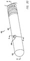
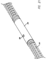
- a radiopaque tip coil 105 is provided at the proximal end of the combination sensor tip 100.
- the radiopaque tip coil 105 is coupled to a proximal coil 106, and the proximal coil 106 may be coupled to the elongate tubular member.
- Another improvement of the present invention over current designs that use separate pressure sensor and ultrasound transducer housings is that the present invention provides a smoother transition from the elongate tubular member to the combination sensor tip 100, i.e. , the connection between the radiopaque tip coil 105, the proximal coil 106, and the rest of the guide wire is optimized relative to current designs.
- the transition is smoother and more flexible because of the absence of the housing between the radiopaque tip coil.105 and the proximal coil 106.
- Current designs such as the prior art guide wire shown in Fig. 1 , generally have a tip coil 5 attached to a pressure sensor housing 3, which in turn is connected to a proximal coil 6.
- the present invention eliminates or greatly reduces the separation between the tip coil and the proximal coil that is required in current devices. Suitable coils for use with the present invention are described in U.S. Patent No. 6,106,476 .
- signals from the ultrasound transducer 101 and the pressure sensor 104 may be carried by fine wire conductors 107 passing through the guide wire to conductive bands 108a-e near the proximal end 110 of the guide wire.
- a guide wire incorporating the combination sensor tip 100 of the present invention includes five electrical conductors 107 extending through the lumen of the guidewire and five conductive bands 108a-e on the proximal end 110 of the guidewire.
- the conductive bands 108a-e may be electrically isolated from each other by means of epoxy 109a-d. Alternatively, polyimide tubes may be used to isolate conductors from the conductive bands.
- the conductive bands transmit the electrical signals from the conductors via a mating connector (or contact housing as described herein with respect to a connector of the present invention) to an instrument, such as, e.g., a physiology monitor, that converts the signals into pressure and velocity readings that are displayed to the user.
- an instrument such as, e.g., a physiology monitor
- algorithms such as Coronary Flow Reserve (CFR) and Fractional Flow Reserve (FFR) are calculated.
- the guide wire of the present invention is comprised of a flexible elongate element having proximal and distal ends and a diameter of 0.457mm (0.018") and less as disclosed in U.S. Patent No. 5,125,137 , U.S. Patent No. 5,163,445 , U.S. Patent No.5, 174,295 , U.S. Patent No. 5,178,159 , U.S. Patent No. 5,226,421 , U.S. patent 5,240,437 and U.S. Patent 6,106,476 .
- a suitable guide wire may consist of a flexible elongate element having proximal and distal extremities, and can be formed of a suitable material such as stainless steel, Nitinol, polyimide, PEEK or other metallic or polymeric materials having an outside diameter for example of 0.457mm (0.018") or less and having a suitable wall thickness, such as, e.g., 0.0254mm (0.001") to 0.0508mm (0.002").
- This flexible elongate element is conventionally called a hypotube.
- the hypotube may have a length of 130 to 170 cm.
- such a guide wire may further include a stainless steel core wire extending from the proximal extremity to the distal extremity of the flexible elongate element to provide the desired torsional properties to facilitate steering of the guide wire in the vessel and to provide strength to the guidewire and prevent kinking.
- the guide wires disclosed in the above mentioned patents may be modified to provide for improved stiffness.
- the hypotube can have an exterior diameter of 0.356mm (0.014") or less.
- the ability to achieve a suitable stiffness of the guidewire becomes a challenge due to space constraints imposed by the both the small outer diameter of the hypotube and the restricted space in the lumen of the hypotube.
- the use of five electrical conductor wires required for a combination pressure and flow sensor as opposed to either two or three wires required for the individual sensor guide wires further increases the challenge.
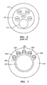
- Fig. 6 depicts the cross-section of a typical prior art guidewire.
- the electrical conductor wires 107a-e extend in the space between the stainless steel core wire 112 and the hypotube 114.
- the annular space between the core wire 112 and the hypotube 114 is further filled with an electrically insulative material 116 such as epoxy or adhesive.
- the stiffness of the guidewire is due mainly to the properties of the core wire 112 and the hypotube 114 and less so to the properties of the electrical conductors 107a-e and insulative material 116.
- the stiffness of the core wire 112 is proportional to the fourth power of the diameter and the stiffness of the hypotube is proportional to the difference between the fourth power of the outer diameter and the fourth power of the inner diameter.
- increasing the diameter of the core wire 112 or increasing the thickness of hypotube 114 are two ways to increase the total stiffness of the cross section.
- space must still exist for the electrical conductors 107a-e to freely extend without damage.
- constraints on outer diameter of the hypotube 114 limit the ability of the prior art designs to improve the stiffness of the guidewire.
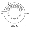
- Fig. 7 depicts a guidewire that allows for increased stiffness while still allowing for the electrical conductors to extend freely.
- the elongate tubular member 124 has thickened walls which further contain a plurality of longitudinal recesses, or grooves, 126a-e disposed on the inner surface and extending the length of the tubular member 124.
- the wire conductors 107a-e may then be positioned in the grooves 126a-e where they will still have space to freely extend the length of the cable. Since the conductors 107a-e are resting partially inside the grooves, the wall thickness of the tubular member 124 may be increased without cutting onto the necessary space for the wire conductors 107a-e.
- the excess space also allows for the stiff inner core wire 122 to be increased in diameter to further reinforce the stiffness of the guidewire.
- the remaining space between the conductors 107a-e and the core wire 122 is filled with insulative material 128.
- Fig. 7a depicts an alternative embodiment of the improved guidewire.
- the elongate tubular member 124 has thickened walls which further contain a single longitudinal recess 129, instead of a plurality of recesses, disposed on the inner surface and extending the length of the tubular member 124.
- the single longitudinal recess 129 is operably sized to house all the conductor wires 107a-e with enough space to permit them to extend freely the length of the elongate tubular member.
- the remaining space between the conductors 107a-e themselves and between the conductors 107a-e and the core wire 122 is filled with insulative material 128.
- the following table shows an example of the increase in wall thickness of the hypotube and core wire diameter a 0.356mm (0.014") guidewire between the embodiments shown in Figs. 6 and 7 .
- the core wire 122 of Fig. 7 is 3.8 times stiffer than the core wire 112 of Fig. 6 .
- tubular member 124 of Fig. 7 is 1.2 times stiffer than the tubular member 114 of Fig. 6 , neglecting any minor effect from the groove(s).
- hypotube wall it is also possible to incorporate only the thickening of the hypotube wall, or only the increase in the core wire diameter. Additionally, if only the wall thickness of the hypotube is increased, and the core wire diameter stays the same, the thickness of the hypotube can be increased even more while still leaving space for the conductor wires and thus the increase of stiffness resulting from the hypotube thickness becomes even greater.
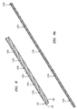
- the guidewire may be created out of a composite polyimide tube wherein the electrical conductor wires 137a-e may be sandwiched between layers of the polyimide tube 130 and 134 as it is being formed.
- the process for making this tube is shown in Figs. 8-9b .
- the first polyimide layer(s) 130 are deposited over a sacrificial mandrel (not shown) whose outer contours are similar to the inner diameter of the hypotube 124 of Fig. 7 .
- Fig. 8 shows five separate insulated wires 137a-e wrapped around the first polymide layer(s) 130.
- the five wires may be supplied on the same flex circuit.
- Each of the wires in Fig. 8 has a conductive core 132 made from a conductive material, such as copper and an insulative coating 131 made from an insulative material, such as polyimide, fluoropolymer, PEBAX or other insulative materials.
- the wires 137a-e are wrapped around the circumference of the tubular form of the first polyimide layer(s) 130.
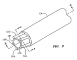
- final layer(s) of polyimide 134 are deposited over the first polyimide layer(s) 130 and the electrical conductor wires 137a-e.
- the resulting composite tube has an inner diameter of, for example 0.229mm, (0.009") and an outer diameter of 0.356mm (0.014").
- the core wire diameter can now be increased to an even greater extent so that it substantially fills the inner diameter of the composite tube, for example a 0.203mm (0.008") diameter core wire may be placed down the inner diameter of a composite tube with a 0.229mm (0.009”) inner diameter.
- Fig. 9a shows a cross section of Fig. 9 taken along line a-a.
- the electrical conductor wires 137a-e are disposed between the polyimide layers 130 and 134.
- Fig. 9b depicts a longitudinal section of Fig. 9 taken along line B-B, showing the electrical conductor wires 137a-e sandwiched between the polyimide layers 130 and 134 of the tubular elongate member.
- the polyimide material is dissected away, and the conductive wires extend to the distal end of the product, where they are attached to the respective sensor, such as the pressure sensor or the ultrasound transducer.
- proximal end assembly i.e. the male connector
- Figs. 10 and 11 The completion of the proximal end assembly, i.e. the male connector, is shown in Figs. 10 and 11 .
- polyimide material is removed by one of many methods familiar in the art, such as cutting, grinding, etching, ablating, burning and drilling. One preferred method is laser machining.
- the polyimide is removed at a point 140a-e (d and e not shown) for each of the five wires: for wire 137a at removal point 140a, for wire 137b at removal point 140b, etc.
- the termination of the male connector is performed by a metal deposition process at a proximal section 162 of the composite tube 160.
- An area made up of intermediate areas 150a, 150b, 150c and 150d is masked and metal is deposited at areas 130a, 130b, 130c, 130d and 130e.
- a process of this nature is described in U.S. Patent No. 6,210,339 .
- the deposited metal (or any conductive material) permanently adheres or couples to the exposed conductive wires at points 140a-e where the polyimide layers were removed. After the masking material 150a-d is removed, there are five independent conductive stripes 130a-e, each connected to a different respective electric wire.
- a male connector is made that is short in length, yet very reliable, in mating with a female connector and cable.
- Any metallizing process is conceived here, including the metallizing of the entire section 162, followed by the etching of the metal material at 150a, 150b, 150c and 150d.
- conductive bands may be coupled to the exposed ends of the electric wires instead of the metallizing process.
- the combination sensor tip 100 is mounted on the distal extremity of the guidewire.
- the guide wire with the combination sensor tip 100 mounted thereon may then be used in connection with a patient lying on a table or a bed in a cath lab of a typical hospital in which a catheterization procedure such as for diagnosis or treatment is being performed on the patient.
- the guide wire may be used with an apparatus, such as a connector, that consists of a cable that connects the guide wire to an interface box.
- the interface box may be connected by another cable to a control console that has incorporated as a part thereof a video screen on which measurements are displayed, such as, e.g. , a waveform displaying ECG measurements as well as representations of the measurements being made by the combination sensor tip 100.
- the ability to measure and compare both the pressure and velocity flow and create an index of hyperemic stenosis resistance significantly improves the diagnostic accuracy of this ischemic testing. It has been shown that distal pressure and velocity measurements, particularly regarding the pressure drop-velocity relationship such as Fractional Flow reserve (FFR), Coronary flow reserve (CFR) and combined P-V curves, reveal information about the stenosis severity.
- FFR Fractional Flow reserve
- CFR Coronary flow reserve
- the guidewire may be advanced to a location on the distal side of the stenosis. The pressure and flow velocity may then be measured at a first flow state. Then, the flow rate may be significantly increased, for example by the use of drugs such as adenosine, and the pressure and flow measured in this second, hyperemic, flow state.
- the pressure and flow relationships at these two flow states are then compared to assess the severity of the stenosis and provide improved guidance for any coronary interventions.
- the ability to take the pressure and flow measurements at the same location and same time with the combination tip sensor, improves the accuracy of these pressure-velocity loops and therefore improves the accuracy of the diagnostic information.
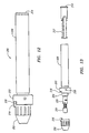
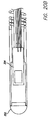
- Figs. 12-15 depict an improved connector used to couple the guide wire with a combination sensor tip to a physiology monitor.
- the connector 200 includes a nosepiece 202 coupled to a connector housing 206, with the nosepiece 202 being located on the distal end of the connector housing 206 and when in use oriented towards the proximal end of a guide wire.
- a retainer 203 is secured to a threaded shell 204 located on the distal end of the connector housing 206 by means of a setscrew 208.
- the retainer 203 limits the rotation of the nosepiece 202 during operation between a locked and unlocked position.
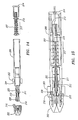
- the connector housing 206 has an inner passage which further contains a stationary contact housing 207 for electrically connecting to the conductors of the coupled guidewire and a rotatable collet/bearing assembly 205 for physically engaging the wire.
- the collet/bearing assembly 205 further comprises a collet head 210 which can be shifted between an open and closed position to alternately engage or disengage a guide wire, a spring 212 and collet housing 209 to facilitate shifting the collet head between the open and closed positions and a rotational bearing 211 which permits the collet/bearing assembly to freely rotate within the connector housing 206.
- a collet head 210 which can be shifted between an open and closed position to alternately engage or disengage a guide wire
- a spring 212 and collet housing 209 to facilitate shifting the collet head between the open and closed positions
- a rotational bearing 211 which permits the collet/bearing assembly to freely rotate within the connector housing 206.
- the ability of the collet/bearing assembly 205 to freely spin within the connector housing 206 acts to reduce the stress on the guidewire joints during steering and handling of the guide wire.
- the free spinning nature of the collet/bearing assembly 205 enables a user to maneuver the guide wire with a reduced amount of torque relative to prior art connectors because torsional resistance is reduced as a result of the spinning movement of the collet/bearing assembly 205.
- the contact housing 207 is located near the proximal end of the connector 200.
- the contact housing further contains a plurality of electrical contacts 217 for connecting with the conductive bands on the proximal end of a guidewire.
- the contact housing 207 does not rotate as the guidewire rotates.
- a connector cable 213 extends proximally from the contact housing 207 through an end cap 214 located at the proximal end of the connector 200.
- the connector cable 213 is configured to be coupled with a cable leading to a physiology monitor.
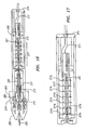
- the nose piece 202 is pressing down on the collet housing 209 and compressing the spring 212 thus allowing for expansion of the collet head 210 which provides an opening through which the guidewire may pass.
- the guide wire 220 may then be inserted into the connector 200 and passed through the collet/bearing assembly 205 and the multiple contacts 217 of the contact housing 207 until the guidewire touches the backplate 215 of the contact housing 207 and a positive stop is felt.
- the conductive bands on the proximal end of the guide wire are lined up with the multiple contacts 217 of the connector housing and are physically in contact with contacts 217 of the contact housing 207.
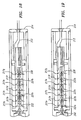
- Fig. 17 depicts a flow guidewire 222 with two conductive bands 227a and 227b located on the proximal end of the guidewire 222.
- the conductive bands 227a and 227b on the flow sensor guidewire 222 make contact with a respective electrical contact 217a and 217b in the contact housing 207.
- Fig. 18 depicts a standalone pressure wire 232 with three conductive bands 237a-b and 238.
- the conductive band 237a makes contact with two electrical contacts 217c-d
- the conductive band 237b makes contact with two electrical contacts 217e-f
- the conductive contact 238 is grounded via contact with 217g.
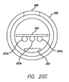
- a combined pressure and flow sensor guidewire wherein the flow sensor conductive bands 217a-b are each in contact with a single electrical contact 217a-b in the contact housing and the pressure sensor ground wire 238 is in contact with a single grounded contact 217g, while the pressure sensor conductive bands 237a-b are each in contact with two electrical contacts 217c-d and 217e-f for redundancy.
- This use of redundant contacts 217c-d and 217e-f for the contact wires 237a-b from the pressure sensor ensures a more reliable electrical contact between the guide wire and the connector 200 is produced because if one dynamic contact fails at any point during rotation of the connector 200 with respect to the contact housing 207, another redundant contact is also connected to assure no lapses.
- the guidewire may then be locked into place by turning the nosepiece 202 to the locked position.
- the spring 212 in the collet/bearing assembly 205 is released causing the collet housing 209 to compress the collet head 210 and thereby engage the guidewire.
- the engaged guidewire will be able to freely rotate with the collet/bearing assembly 205, however the longitudinal position of the guidewire will remain fixed. This ensures that the conductive bands of the guidewire will remain in contact with their respective contacts 217 in the contact housing 207 despite the rotational movement of the guidewire.
- the alighment of the electrical contacts of the guidewire with at least two contacts in the contact housing further ensures the reliability of electrical connection etween the guidewire and the contacts in the connector.
- turning the nosepiece 202 approximately a quarter turn locks the guide wire in place and turning the nosepiece 202 approximately a quarter turn in the reverse direction unlocks the guide wire from the connector 200.
- This is achieved by using a left hand (reverse) thread.
- the reverse direction is used to allow the connector to operate with clockwise attachment and counterclockwise detachment, thus ensuring the motion is intuitive to the user.
- a stop tab 216 on the nosepiece 202 is configured to contact the locked position 218 on the retainer 203 when the nosepiece 202 is locked, and thereby to provide tactile feedback to the user indicating whether the connector 200 is locked or unlocked.
- the connector 200 is relatively simple to operate due to the uncomplicated manner of locking and unlocking the guide wire by turning the nosepiece 202 approximately one quarter turn in either of two directions.
Landscapes
- Health & Medical Sciences (AREA)
- Life Sciences & Earth Sciences (AREA)
- Physics & Mathematics (AREA)
- Biophysics (AREA)
- Veterinary Medicine (AREA)
- Pathology (AREA)
- Public Health (AREA)
- Engineering & Computer Science (AREA)
- Biomedical Technology (AREA)
- Heart & Thoracic Surgery (AREA)
- Medical Informatics (AREA)
- Molecular Biology (AREA)
- Surgery (AREA)
- Animal Behavior & Ethology (AREA)
- General Health & Medical Sciences (AREA)
- Radiology & Medical Imaging (AREA)
- Nuclear Medicine, Radiotherapy & Molecular Imaging (AREA)
- Cardiology (AREA)
- Hematology (AREA)
- Vascular Medicine (AREA)
- Physiology (AREA)
- Measuring Pulse, Heart Rate, Blood Pressure Or Blood Flow (AREA)
- Media Introduction/Drainage Providing Device (AREA)
- Ultra Sonic Daignosis Equipment (AREA)
- Measuring Fluid Pressure (AREA)
Claims (8)
- Pointe de capteurs combinés (100);
comprenant un boîtier de capteurs combinés (103, 300) comprenant en outre une paroi extérieure et une extrémité distale (102, 312) et une extrémité proximale (314), ayant une lumière (310) s'étendant entre celles-ci, le boîtier de capteurs étant apte à être disposé près d'une extrémité distale d'un fil-guide (220);
une bobine (105, 106) disposée proximalement du boîtier de capteurs pour la fixation au fil-guide;
un capteur de pression (104, 304) fixé au boîtier de capteurs; et
un capteur d'écoulement (101) disposé dans la lumière du boîtier vers l'extrémité distale du boîtier et à proximité étroite du capteur de pression;
où le capteur de pression et le capteur d'écoulement sont positionnés dans le boîtier des capteurs combinés de telle sorte qu'une distance entre le capteur de pression et le capteur d'écoulement est sensiblement éliminée;
caractérisée en ce que le capteur d'écoulement est un transducteur ultrasonique. - Pointe de capteurs combinés selon la revendication 1, où le boîtier de capteurs comprend en outre une découpure, et le capteur de pression est installé dans la découpure de telle sorte qu'une surface extérieure du capteur de pression est sensiblement en affleurement avec la paroi extérieure du boîtier de capteurs.
- Pointe de capteurs de combinaison selon la revendication 2, où le capteur de pression est installé dans une position en porte-à-faux dans le boîtier de capteurs combinés.
- Pointe de capteurs combinés selon la revendication 1, où le capteur de pression comprend en outre une membrane.
- Pointe de capteurs combinés selon la revendication 1, où le capteur de pression comprend en outre un cristal semi-conducteur.
- Pointe de capteurs combinés selon la revendication 1, où le capteur d'écoulement est disposé à la pointe distale du boîtier de capteurs combinés.
- Pointe de capteurs combinés selon la revendication 1, où la bobine comprend en outre:une bobine à pointe radio-opaque (105) couplée à une extrémité proximale du boîtier de capteurs combinés; etune bobine proximale (106) couplée à la bobine à pointe radio-opaque et configurée pour le couplage à un fil-guide.
- Pointe de capteurs combinés selon la revendication 1, où chacun du capteur de pression et du capteur d'écoulement sont décalés de l'extrémité distale du boîtier de capteurs combinés d'une distance comprise entre 1,5cm et 3,0cm.
Priority Applications (2)
| Application Number | Priority Date | Filing Date | Title |
|---|---|---|---|
| EP13169255.0A EP2638862B1 (fr) | 2004-09-27 | 2005-09-27 | Fil-guide de détection combinée amélioré et procédés d'utilisation |
| EP12179715.3A EP2570076B1 (fr) | 2004-09-27 | 2005-09-27 | Fil-guide de détection combinée améliorée |
Applications Claiming Priority (3)
| Application Number | Priority Date | Filing Date | Title |
|---|---|---|---|
| US61384704P | 2004-09-27 | 2004-09-27 | |
| US11/236,318 US8277386B2 (en) | 2004-09-27 | 2005-09-26 | Combination sensor guidewire and methods of use |
| PCT/US2005/034959 WO2006037082A2 (fr) | 2004-09-27 | 2005-09-27 | Capteurs combines ameliores, fil-guide et procedes d'utilisation correspondants |
Related Child Applications (3)
| Application Number | Title | Priority Date | Filing Date |
|---|---|---|---|
| EP13169255.0A Division EP2638862B1 (fr) | 2004-09-27 | 2005-09-27 | Fil-guide de détection combinée amélioré et procédés d'utilisation |
| EP12179715.3A Division EP2570076B1 (fr) | 2004-09-27 | 2005-09-27 | Fil-guide de détection combinée améliorée |
| EP12179715.3A Division-Into EP2570076B1 (fr) | 2004-09-27 | 2005-09-27 | Fil-guide de détection combinée améliorée |
Publications (3)
| Publication Number | Publication Date |
|---|---|
| EP1804675A2 EP1804675A2 (fr) | 2007-07-11 |
| EP1804675A4 EP1804675A4 (fr) | 2010-07-07 |
| EP1804675B1 true EP1804675B1 (fr) | 2012-09-12 |
Family
ID=36119590
Family Applications (3)
| Application Number | Title | Priority Date | Filing Date |
|---|---|---|---|
| EP13169255.0A Active EP2638862B1 (fr) | 2004-09-27 | 2005-09-27 | Fil-guide de détection combinée amélioré et procédés d'utilisation |
| EP05800066A Active EP1804675B1 (fr) | 2004-09-27 | 2005-09-27 | Capteurs combines ameliores, fil-guide |
| EP12179715.3A Active EP2570076B1 (fr) | 2004-09-27 | 2005-09-27 | Fil-guide de détection combinée améliorée |
Family Applications Before (1)
| Application Number | Title | Priority Date | Filing Date |
|---|---|---|---|
| EP13169255.0A Active EP2638862B1 (fr) | 2004-09-27 | 2005-09-27 | Fil-guide de détection combinée amélioré et procédés d'utilisation |
Family Applications After (1)
| Application Number | Title | Priority Date | Filing Date |
|---|---|---|---|
| EP12179715.3A Active EP2570076B1 (fr) | 2004-09-27 | 2005-09-27 | Fil-guide de détection combinée améliorée |
Country Status (5)
| Country | Link |
|---|---|
| US (4) | US8277386B2 (fr) |
| EP (3) | EP2638862B1 (fr) |
| JP (1) | JP5016491B2 (fr) |
| ES (1) | ES2591006T3 (fr) |
| WO (1) | WO2006037082A2 (fr) |
Families Citing this family (231)
| Publication number | Priority date | Publication date | Assignee | Title |
|---|---|---|---|---|
| WO1996007351A1 (fr) | 1994-09-02 | 1996-03-14 | Cardiometrics, Inc. | Capteur de pression ultra-miniaturise et fil de guidage equipe de ce dernier et procede associe |
| DE10105592A1 (de) | 2001-02-06 | 2002-08-08 | Achim Goepferich | Platzhalter zur Arzneistofffreigabe in der Stirnhöhle |
| US8317816B2 (en) | 2002-09-30 | 2012-11-27 | Acclarent, Inc. | Balloon catheters and methods for treating paranasal sinuses |
| US7361168B2 (en) | 2004-04-21 | 2008-04-22 | Acclarent, Inc. | Implantable device and methods for delivering drugs and other substances to treat sinusitis and other disorders |
| US7410480B2 (en) | 2004-04-21 | 2008-08-12 | Acclarent, Inc. | Devices and methods for delivering therapeutic substances for the treatment of sinusitis and other disorders |
| US7803150B2 (en) | 2004-04-21 | 2010-09-28 | Acclarent, Inc. | Devices, systems and methods useable for treating sinusitis |
| US9554691B2 (en) | 2004-04-21 | 2017-01-31 | Acclarent, Inc. | Endoscopic methods and devices for transnasal procedures |
| US20060004323A1 (en) | 2004-04-21 | 2006-01-05 | Exploramed Nc1, Inc. | Apparatus and methods for dilating and modifying ostia of paranasal sinuses and other intranasal or paranasal structures |
| US20070167682A1 (en) | 2004-04-21 | 2007-07-19 | Acclarent, Inc. | Endoscopic methods and devices for transnasal procedures |
| US8702626B1 (en) | 2004-04-21 | 2014-04-22 | Acclarent, Inc. | Guidewires for performing image guided procedures |
| US8894614B2 (en) | 2004-04-21 | 2014-11-25 | Acclarent, Inc. | Devices, systems and methods useable for treating frontal sinusitis |
| US7419497B2 (en) | 2004-04-21 | 2008-09-02 | Acclarent, Inc. | Methods for treating ethmoid disease |
| US9089258B2 (en) | 2004-04-21 | 2015-07-28 | Acclarent, Inc. | Endoscopic methods and devices for transnasal procedures |
| US9399121B2 (en) | 2004-04-21 | 2016-07-26 | Acclarent, Inc. | Systems and methods for transnasal dilation of passageways in the ear, nose or throat |
| US7654997B2 (en) | 2004-04-21 | 2010-02-02 | Acclarent, Inc. | Devices, systems and methods for diagnosing and treating sinusitus and other disorders of the ears, nose and/or throat |
| US7559925B2 (en) | 2006-09-15 | 2009-07-14 | Acclarent Inc. | Methods and devices for facilitating visualization in a surgical environment |
| US8932276B1 (en) | 2004-04-21 | 2015-01-13 | Acclarent, Inc. | Shapeable guide catheters and related methods |
| US9101384B2 (en) | 2004-04-21 | 2015-08-11 | Acclarent, Inc. | Devices, systems and methods for diagnosing and treating sinusitis and other disorders of the ears, Nose and/or throat |
| US20070208252A1 (en) | 2004-04-21 | 2007-09-06 | Acclarent, Inc. | Systems and methods for performing image guided procedures within the ear, nose, throat and paranasal sinuses |
| US8764729B2 (en) | 2004-04-21 | 2014-07-01 | Acclarent, Inc. | Frontal sinus spacer |
| US7462175B2 (en) | 2004-04-21 | 2008-12-09 | Acclarent, Inc. | Devices, systems and methods for treating disorders of the ear, nose and throat |
| US9351750B2 (en) | 2004-04-21 | 2016-05-31 | Acclarent, Inc. | Devices and methods for treating maxillary sinus disease |
| US10188413B1 (en) | 2004-04-21 | 2019-01-29 | Acclarent, Inc. | Deflectable guide catheters and related methods |
| US8146400B2 (en) * | 2004-04-21 | 2012-04-03 | Acclarent, Inc. | Endoscopic methods and devices for transnasal procedures |
| US8747389B2 (en) | 2004-04-21 | 2014-06-10 | Acclarent, Inc. | Systems for treating disorders of the ear, nose and throat |
| US20060063973A1 (en) | 2004-04-21 | 2006-03-23 | Acclarent, Inc. | Methods and apparatus for treating disorders of the ear, nose and throat |
| US20190314620A1 (en) | 2004-04-21 | 2019-10-17 | Acclarent, Inc. | Apparatus and methods for dilating and modifying ostia of paranasal sinuses and other intranasal or paranasal structures |
| US8277386B2 (en) | 2004-09-27 | 2012-10-02 | Volcano Corporation | Combination sensor guidewire and methods of use |
| US7891085B1 (en) | 2005-01-11 | 2011-02-22 | Boston Scientific Neuromodulation Corporation | Electrode array assembly and method of making same |
| US8951225B2 (en) | 2005-06-10 | 2015-02-10 | Acclarent, Inc. | Catheters with non-removable guide members useable for treatment of sinusitis |
| US8114113B2 (en) | 2005-09-23 | 2012-02-14 | Acclarent, Inc. | Multi-conduit balloon catheter |
| US8608703B2 (en) | 2007-06-12 | 2013-12-17 | Medrad, Inc. | Infusion flow guidewire system |
| EP1849409B1 (fr) * | 2006-04-28 | 2010-06-02 | Radi Medical Systems Ab | Ensemble de capteur et fil-guide |
| US8190389B2 (en) | 2006-05-17 | 2012-05-29 | Acclarent, Inc. | Adapter for attaching electromagnetic image guidance components to a medical device |
| US9867530B2 (en) | 2006-08-14 | 2018-01-16 | Volcano Corporation | Telescopic side port catheter device with imaging system and method for accessing side branch occlusions |
| US9820688B2 (en) | 2006-09-15 | 2017-11-21 | Acclarent, Inc. | Sinus illumination lightwire device |
| US8174395B2 (en) * | 2006-11-20 | 2012-05-08 | St. Jude Medical Systems Ab | Transceiver unit in a measurement system |
| US11234650B2 (en) | 2006-11-20 | 2022-02-01 | St. Jude Medical Coordination Center Bvba | Measurement system |
| US8439687B1 (en) | 2006-12-29 | 2013-05-14 | Acclarent, Inc. | Apparatus and method for simulated insertion and positioning of guidewares and other interventional devices |
| WO2008124787A2 (fr) * | 2007-04-09 | 2008-10-16 | Acclarent, Inc. | Système d'ethmoïdotomie et dispositifs espaceurs implantables capables de délivrer une substance thérapeutique pour le traitement de la sinusite paranasale |
| EP2146769A1 (fr) * | 2007-04-23 | 2010-01-27 | Interventional & Surgical Innovations, LLC | Fil de guidage à rigidité ajustable |
| US9387308B2 (en) | 2007-04-23 | 2016-07-12 | Cardioguidance Biomedical, Llc | Guidewire with adjustable stiffness |
| US8118757B2 (en) | 2007-04-30 | 2012-02-21 | Acclarent, Inc. | Methods and devices for ostium measurement |
| US8485199B2 (en) | 2007-05-08 | 2013-07-16 | Acclarent, Inc. | Methods and devices for protecting nasal turbinate during surgery |
| WO2009009802A1 (fr) * | 2007-07-12 | 2009-01-15 | Volcano Corporation | Cathéter oct-ivus pour imagerie luminale simultanée |
| US9596993B2 (en) | 2007-07-12 | 2017-03-21 | Volcano Corporation | Automatic calibration systems and methods of use |
| EP2178442B1 (fr) | 2007-07-12 | 2017-09-06 | Volcano Corporation | Cathéter pour imagerie in-vivo |
| US9566418B2 (en) * | 2007-10-26 | 2017-02-14 | St. Jude Medical Coordination Center Bvba | Sensor guide wire with micro-cable winding |
| US10206821B2 (en) | 2007-12-20 | 2019-02-19 | Acclarent, Inc. | Eustachian tube dilation balloon with ventilation path |
| US8182432B2 (en) | 2008-03-10 | 2012-05-22 | Acclarent, Inc. | Corewire design and construction for medical devices |
| AU2009276553B2 (en) | 2008-07-30 | 2015-02-05 | Acclarent, Inc. | Paranasal ostium finder devices and methods |
| US8298156B2 (en) | 2008-09-11 | 2012-10-30 | Acist Medical Systems, Inc. | Physiological sensor delivery device and method |
| AU2009293312B2 (en) | 2008-09-18 | 2015-07-09 | Acclarent, Inc. | Methods and apparatus for treating disorders of the ear nose and throat |
| US8594799B2 (en) * | 2008-10-31 | 2013-11-26 | Advanced Bionics | Cochlear electrode insertion |
| US20100241155A1 (en) | 2009-03-20 | 2010-09-23 | Acclarent, Inc. | Guide system with suction |
| US8435290B2 (en) | 2009-03-31 | 2013-05-07 | Acclarent, Inc. | System and method for treatment of non-ventilating middle ear by providing a gas pathway through the nasopharynx |
| US7978742B1 (en) | 2010-03-24 | 2011-07-12 | Corning Incorporated | Methods for operating diode lasers |
| US11490826B2 (en) | 2009-07-14 | 2022-11-08 | The General Hospital Corporation | Apparatus, systems and methods for measuring flow and pressure within a vessel |
| US9211403B2 (en) * | 2009-10-30 | 2015-12-15 | Advanced Bionics, Llc | Steerable stylet |
| GB2479340A (en) * | 2010-03-10 | 2011-10-12 | Imp Innovations Ltd | Method and apparatus for the measurement of a fluid flow restriction in a vessel |
| SE535022C2 (sv) | 2010-06-30 | 2012-03-20 | St Jude Medical Systems Ab | Sensorguidewire innefattande en sensorkapsel med multipla hål |
| WO2012021697A1 (fr) | 2010-08-12 | 2012-02-16 | Medrad, Inc. | Système de flux de perfusion et couplage fluidique |
| US9155492B2 (en) | 2010-09-24 | 2015-10-13 | Acclarent, Inc. | Sinus illumination lightwire device |
| CA2811561C (fr) * | 2010-09-29 | 2017-01-17 | St. Jude Medical Systems Ab | Fil-guide a capteur |
| US20120105230A1 (en) * | 2010-10-27 | 2012-05-03 | Thomas Bockstoce | Anti-theft sensor system |
| CA2808202C (fr) * | 2010-11-09 | 2013-11-05 | Opsens Inc. | Fil-guide avec capteur de pression interne |
| US11141063B2 (en) | 2010-12-23 | 2021-10-12 | Philips Image Guided Therapy Corporation | Integrated system architectures and methods of use |
| US8764683B2 (en) | 2010-12-29 | 2014-07-01 | Mediguide Ltd. | Medical device guidewire with a position sensor |
| US11040140B2 (en) | 2010-12-31 | 2021-06-22 | Philips Image Guided Therapy Corporation | Deep vein thrombosis therapeutic methods |
| WO2012092441A2 (fr) * | 2010-12-31 | 2012-07-05 | Volcano Corporation | Système de fil guide de détection de pression basé sur le lumen doté d'une correction de la distorsion |
| GB201100137D0 (en) | 2011-01-06 | 2011-02-23 | Davies Helen C S | Apparatus and method of assessing a narrowing in a fluid tube |
| US10092271B2 (en) | 2011-04-13 | 2018-10-09 | Cornell University | Ultrasound transducer probe and methods |
| EP2706908B1 (fr) | 2011-05-11 | 2019-07-10 | Acist Medical Systems, Inc. | Système de détection intravasculaire |
| CA2837577C (fr) * | 2011-05-27 | 2018-05-29 | Lightlab Imaging, Inc. | Systemes et procedes a base de tomographie par coherence optique et de pression |
| JP5814860B2 (ja) | 2011-05-31 | 2015-11-17 | ライトラボ・イメージング・インコーポレーテッド | 多モード撮像システム、装置、および方法 |
| CN103619401B (zh) * | 2011-06-23 | 2017-03-29 | 皇家飞利浦有限公司 | 复合纤维导丝 |
| US9314584B1 (en) | 2011-06-27 | 2016-04-19 | Bayer Healthcare Llc | Method and apparatus for fractional flow reserve measurements |
| JP6133864B2 (ja) | 2011-08-20 | 2017-05-24 | ボルケーノ コーポレイション | 脈管を視覚的に描写し、処置オプションを評価するための装置、システム及び方法 |
| US9339348B2 (en) | 2011-08-20 | 2016-05-17 | Imperial Colege of Science, Technology and Medicine | Devices, systems, and methods for assessing a vessel |
| WO2013028737A1 (fr) * | 2011-08-22 | 2013-02-28 | Lake Region Manufacturing, Inc. D/B/A | Fil-guide multiconducteur, de faible profil |
| US9360630B2 (en) | 2011-08-31 | 2016-06-07 | Volcano Corporation | Optical-electrical rotary joint and methods of use |
| US9734938B2 (en) * | 2011-10-06 | 2017-08-15 | 3Dt Holdings, Llc | Devices and systems for obtaining conductance data and methods of manufacturing and using the same |
| US11373780B2 (en) | 2011-10-06 | 2022-06-28 | 3Dt Holdings, Llc | Methods to generate elongated wires having a metallic substrate thereon and devices comprising the same |
| EP2765907B1 (fr) | 2011-10-14 | 2016-05-18 | Acist Medical Systems, Inc. | Dispositif de mesure d'une structure anatomique |
| SE537177C2 (sv) * | 2011-10-28 | 2015-02-24 | St Jude Medical Systems Ab | Medicinskt system för bestämning av Fractional Flow Reserve(FFR) värdet |
| WO2013082032A1 (fr) * | 2011-11-28 | 2013-06-06 | Mazar Scott T | Fil-guide orientable à capteur de pression |
| EP2804525A4 (fr) * | 2012-01-19 | 2015-12-09 | Volcano Corp | Dispositifs, systèmes et procédés d'interface utilisables avec des dispositifs de surveillance de la pression intravasculaire |
| US9549679B2 (en) * | 2012-05-14 | 2017-01-24 | Acist Medical Systems, Inc. | Multiple transducer delivery device and method |
| US10506934B2 (en) | 2012-05-25 | 2019-12-17 | Phyzhon Health Inc. | Optical fiber pressure sensor |
| JP2015523149A (ja) | 2012-06-28 | 2015-08-13 | ヴォルカノ コーポレイションVolcano Corporation | 脈管内の装置とともに使用するための側方ローディング・コネクタ及び関連システム及び方法 |
| US9974446B2 (en) * | 2012-08-31 | 2018-05-22 | Volcano Corporation | Mounting structures for components of intravascular devices |
| US9895108B2 (en) | 2012-08-31 | 2018-02-20 | Volcano Corporation | Pressure sensing intravascular devices with reduced drift and associated systems and methods |
| CN104619247B (zh) * | 2012-09-17 | 2017-10-27 | 波士顿科学西美德公司 | 压力感测导丝 |
| US20140086461A1 (en) | 2012-09-25 | 2014-03-27 | The Johns Hopkins University | Method and system for determining time-based index for blood circulation from angiographic imaging data |
| US11272845B2 (en) | 2012-10-05 | 2022-03-15 | Philips Image Guided Therapy Corporation | System and method for instant and automatic border detection |
| US9324141B2 (en) | 2012-10-05 | 2016-04-26 | Volcano Corporation | Removal of A-scan streaking artifact |
| EP2904671B1 (fr) | 2012-10-05 | 2022-05-04 | David Welford | Systèmes et procédés pour amplifier la lumière |
| US9292918B2 (en) | 2012-10-05 | 2016-03-22 | Volcano Corporation | Methods and systems for transforming luminal images |
| US10070827B2 (en) | 2012-10-05 | 2018-09-11 | Volcano Corporation | Automatic image playback |
| US9286673B2 (en) | 2012-10-05 | 2016-03-15 | Volcano Corporation | Systems for correcting distortions in a medical image and methods of use thereof |
| US9367965B2 (en) | 2012-10-05 | 2016-06-14 | Volcano Corporation | Systems and methods for generating images of tissue |
| US9858668B2 (en) | 2012-10-05 | 2018-01-02 | Volcano Corporation | Guidewire artifact removal in images |
| US9307926B2 (en) | 2012-10-05 | 2016-04-12 | Volcano Corporation | Automatic stent detection |
| US10568586B2 (en) | 2012-10-05 | 2020-02-25 | Volcano Corporation | Systems for indicating parameters in an imaging data set and methods of use |
| US9840734B2 (en) | 2012-10-22 | 2017-12-12 | Raindance Technologies, Inc. | Methods for analyzing DNA |
| US9700215B2 (en) * | 2012-10-24 | 2017-07-11 | Makaha Medical, Llc. | Systems and methods for assessing vasculature health and blood clots |
| EP2931132B1 (fr) | 2012-12-13 | 2023-07-05 | Philips Image Guided Therapy Corporation | Dispositif de canulation ciblée |
| EP2934336B1 (fr) | 2012-12-18 | 2018-09-05 | Volcano Corporation | Région de transition comprenant des ouvertures et un biseau pour un cathéter d'imagerie |
| US11406498B2 (en) | 2012-12-20 | 2022-08-09 | Philips Image Guided Therapy Corporation | Implant delivery system and implants |
| US10942022B2 (en) | 2012-12-20 | 2021-03-09 | Philips Image Guided Therapy Corporation | Manual calibration of imaging system |
| US10939826B2 (en) | 2012-12-20 | 2021-03-09 | Philips Image Guided Therapy Corporation | Aspirating and removing biological material |
| EP2934311B1 (fr) | 2012-12-20 | 2020-04-15 | Volcano Corporation | Cathéters de transition sans heurt |
| JP2016504589A (ja) | 2012-12-20 | 2016-02-12 | ナサニエル ジェイ. ケンプ, | 異なる撮像モード間で再構成可能な光コヒーレンストモグラフィシステム |
| US9730613B2 (en) | 2012-12-20 | 2017-08-15 | Volcano Corporation | Locating intravascular images |
| US10413317B2 (en) | 2012-12-21 | 2019-09-17 | Volcano Corporation | System and method for catheter steering and operation |
| US10332228B2 (en) | 2012-12-21 | 2019-06-25 | Volcano Corporation | System and method for graphical processing of medical data |
| EP2934653B1 (fr) | 2012-12-21 | 2018-09-19 | Douglas Meyer | Cathéter d'imagerie ultrasonore rotatif muni d'un télescope de corps de cathéter étendu |
| US9486143B2 (en) | 2012-12-21 | 2016-11-08 | Volcano Corporation | Intravascular forward imaging device |
| US20140180066A1 (en) | 2012-12-21 | 2014-06-26 | Volcano Corporation | Introducer having a flow sensor |
| US9612105B2 (en) | 2012-12-21 | 2017-04-04 | Volcano Corporation | Polarization sensitive optical coherence tomography system |
| US10058284B2 (en) | 2012-12-21 | 2018-08-28 | Volcano Corporation | Simultaneous imaging, monitoring, and therapy |
| EP2936241B1 (fr) | 2012-12-21 | 2020-10-21 | Nathaniel J. Kemp | Mise en tampon optique efficace en énergie utilisant un commutateur optique actif à maintien de polarisation |
| US10166003B2 (en) | 2012-12-21 | 2019-01-01 | Volcano Corporation | Ultrasound imaging with variable line density |
| WO2014100579A1 (fr) | 2012-12-21 | 2014-06-26 | David Anderson | Technique et représentation de mesure de gain fonctionnel |
| JP2016507892A (ja) | 2012-12-21 | 2016-03-10 | デイビッド ウェルフォード, | 光の波長放出を狭幅化するためのシステムおよび方法 |
| WO2014100458A1 (fr) * | 2012-12-21 | 2014-06-26 | Volcano Corporation | Structures de montage pour composants de dispositifs intravasculaires |
| US20140180028A1 (en) * | 2012-12-21 | 2014-06-26 | Volcano Corporation | Guidewire with adjustable tip |
| JP2016501623A (ja) | 2012-12-21 | 2016-01-21 | アンドリュー ハンコック, | 画像信号のマルチ経路処理のためのシステムおよび方法 |
| WO2014105578A1 (fr) * | 2012-12-27 | 2014-07-03 | Volcano Corporation | Fil-guide intravasculaire avec partie d'extrémité distale hyperflexible |
| US20140187978A1 (en) * | 2012-12-28 | 2014-07-03 | Volcano Corporation | Intravascular Devices Having Information Stored Thereon And/Or Wireless Communication Functionality, Including Associated Devices, Systems, And Methods |
| WO2014106158A1 (fr) * | 2012-12-31 | 2014-07-03 | Volcano Corporation | Dispositifs intravasculaires, systèmes, et procédés associés |
| US9757591B2 (en) | 2013-02-11 | 2017-09-12 | Bayer Healthcare Llc | Methods and systems for monitoring an automated infusion system |
| US10226597B2 (en) | 2013-03-07 | 2019-03-12 | Volcano Corporation | Guidewire with centering mechanism |
| EP2965263B1 (fr) | 2013-03-07 | 2022-07-20 | Bernhard Sturm | Segmentation multimodale dans des images intravasculaires |
| US20140276923A1 (en) | 2013-03-12 | 2014-09-18 | Volcano Corporation | Vibrating catheter and methods of use |
| WO2014164696A1 (fr) | 2013-03-12 | 2014-10-09 | Collins Donna | Systèmes et procédés de diagnostic d'une maladie microvasculaire coronarienne |
| WO2014159819A1 (fr) | 2013-03-13 | 2014-10-02 | Jinhyoung Park | Système et procédés pour produire une image à partir d'un dispositif ultrasonore intravasculaire rotatif |
| US11026591B2 (en) | 2013-03-13 | 2021-06-08 | Philips Image Guided Therapy Corporation | Intravascular pressure sensor calibration |
| US9301687B2 (en) | 2013-03-13 | 2016-04-05 | Volcano Corporation | System and method for OCT depth calibration |
| US10219887B2 (en) | 2013-03-14 | 2019-03-05 | Volcano Corporation | Filters with echogenic characteristics |
| US10292677B2 (en) | 2013-03-14 | 2019-05-21 | Volcano Corporation | Endoluminal filter having enhanced echogenic properties |
| WO2014152365A2 (fr) | 2013-03-14 | 2014-09-25 | Volcano Corporation | Filtres ayant des caractéristiques échogènes |
| US9629684B2 (en) | 2013-03-15 | 2017-04-25 | Acclarent, Inc. | Apparatus and method for treatment of ethmoid sinusitis |
| US9433437B2 (en) | 2013-03-15 | 2016-09-06 | Acclarent, Inc. | Apparatus and method for treatment of ethmoid sinusitis |
| JP2016517333A (ja) * | 2013-03-15 | 2016-06-16 | ボルケーノ コーポレイション | 圧力及び超音波機能を持つ遠位保護システム及び方法 |
| WO2014151830A1 (fr) | 2013-03-15 | 2014-09-25 | Volcano Corporation | Dispositifs d'interface, systèmes et procédés à utiliser avec des dispositifs de contrôle de la pression intravasculaire |
| US10835183B2 (en) | 2013-07-01 | 2020-11-17 | Zurich Medical Corporation | Apparatus and method for intravascular measurements |
| AU2014284381B2 (en) | 2013-07-01 | 2019-04-18 | Zurich Medical Corporation | Apparatus and method for intravascular measurements |
| WO2015013638A1 (fr) * | 2013-07-26 | 2015-01-29 | Volcano Corporation | Structures de connexion pour dispositifs intravasculaires et systèmes et procédés associés |
| WO2015051003A1 (fr) | 2013-10-04 | 2015-04-09 | Vascular Imaging Corporation | Techniques d'imagerie utilisant un fil-guide d'imagerie |
| US9877660B2 (en) | 2013-11-14 | 2018-01-30 | Medtronic Vascular Galway | Systems and methods for determining fractional flow reserve without adenosine or other pharmalogical agent |
| US10130269B2 (en) | 2013-11-14 | 2018-11-20 | Medtronic Vascular, Inc | Dual lumen catheter for providing a vascular pressure measurement |
| US10537255B2 (en) | 2013-11-21 | 2020-01-21 | Phyzhon Health Inc. | Optical fiber pressure sensor |
| WO2015077328A1 (fr) | 2013-11-22 | 2015-05-28 | Volcano Corporation | Ensemble de montage de capteur pour fil-guide détecté, et dispositifs, systèmes et procédés associés |
| WO2015108957A1 (fr) | 2014-01-14 | 2015-07-23 | Volcano Corporation | Systèmes pour améliorer un site d'accès artérioveineux |
| WO2015108973A1 (fr) | 2014-01-14 | 2015-07-23 | Volcano Corporation | Méthodes et systèmes pour éliminer un thrombus d'un site d'accès vasculaire |
| EP3094273A1 (fr) | 2014-01-14 | 2016-11-23 | Volcano Corporation | Dispositifs et procédés de formation d'un accès vasculaire |
| CN106163386B (zh) * | 2014-01-14 | 2019-08-06 | 火山公司 | 用于评估血液透析动静脉瘘管成熟的系统和方法 |
| US9913585B2 (en) | 2014-01-15 | 2018-03-13 | Medtronic Vascular, Inc. | Catheter for providing vascular pressure measurements |
| EP3102098B1 (fr) * | 2014-02-03 | 2022-06-22 | Philips Image Guided Therapy Corporation | Dispositifs, systèmes et procédés intravasculaires ayant un fil d'âme ayant des conducteurs intégrés |
| US10213182B2 (en) | 2014-03-26 | 2019-02-26 | Volcano Corporation | Devices, systems, and methods for assessing a vessel utilizing angled flow-sensing elements |
| JP6586425B2 (ja) | 2014-04-21 | 2019-10-02 | コーニンクレッカ フィリップス エヌ ヴェKoninklijke Philips N.V. | 係合されるコア要素を伴う別々のセクションを有する血管内デバイス、システム及び方法 |
| WO2015164301A1 (fr) | 2014-04-23 | 2015-10-29 | Koninklijke Philips N.V. | Cathéter ayant un dispositif de commande intégré pour l'imagerie et la détection de pression |
| US10244951B2 (en) | 2014-06-10 | 2019-04-02 | Acist Medical Systems, Inc. | Physiological sensor delivery device and method |
| US11330989B2 (en) | 2014-06-16 | 2022-05-17 | Medtronic Vascular, Inc. | Microcatheter sensor design for mounting sensor to minimize induced strain |
| US10973418B2 (en) | 2014-06-16 | 2021-04-13 | Medtronic Vascular, Inc. | Microcatheter sensor design for minimizing profile and impact of wire strain on sensor |
| US10201284B2 (en) | 2014-06-16 | 2019-02-12 | Medtronic Vascular Inc. | Pressure measuring catheter having reduced error from bending stresses |
| US10625055B2 (en) * | 2014-06-26 | 2020-04-21 | The Cleveland Clinic Foundation | Method and apparatus for tracking a position of a medical device |
| US10675003B2 (en) | 2014-07-11 | 2020-06-09 | Acist Medical Systems, Inc. | Intravascular imaging |
| CN116172611A (zh) | 2014-07-15 | 2023-05-30 | 皇家飞利浦有限公司 | 肝内分流的设备和方法 |
| WO2016027198A1 (fr) | 2014-08-21 | 2016-02-25 | Koninklijke Philips N.V. | Dispositif et procédés pour traverser des occlusions |
| WO2016034982A1 (fr) * | 2014-09-04 | 2016-03-10 | Koninklijke Philips N.V. | Cathéter à retrait de fil-guide sous pression |
| WO2016046710A1 (fr) | 2014-09-24 | 2016-03-31 | Koninklijke Philips N.V. | Filtre endoluminal ayant de meilleurs propriétés échogènes |
| FR3026631B1 (fr) | 2014-10-03 | 2016-12-09 | Ecole Polytech | Dispositif medical implantable muni de capteurs |
| WO2016071822A1 (fr) | 2014-11-03 | 2016-05-12 | Koninklijke Philips N.V. | Dispositifs, systèmes et procédés intravasculaires ayant une pointe flexible modelée radio-opaque |
| US10080872B2 (en) | 2014-11-04 | 2018-09-25 | Abbott Cardiovascular Systems Inc. | System and method for FFR guidewire recovery |
| US10258240B1 (en) | 2014-11-24 | 2019-04-16 | Vascular Imaging Corporation | Optical fiber pressure sensor |
| US10194812B2 (en) | 2014-12-12 | 2019-02-05 | Medtronic Vascular, Inc. | System and method of integrating a fractional flow reserve device with a conventional hemodynamic monitoring system |
| US10105107B2 (en) | 2015-01-08 | 2018-10-23 | St. Jude Medical International Holding S.À R.L. | Medical system having combined and synergized data output from multiple independent inputs |
| CN107113549B (zh) | 2015-04-24 | 2020-06-23 | 惠普发展公司有限责任合伙企业 | 路由信号的设备、方法和存储介质 |
| EP3302676B1 (fr) * | 2015-05-29 | 2023-07-12 | Microvention, Inc. | Circuit de cathéter |
| WO2016209665A1 (fr) * | 2015-06-23 | 2016-12-29 | Zurich Medical Corporation | Appareil et procédé pour mesures intravasculaires |
| US20170000456A1 (en) * | 2015-07-01 | 2017-01-05 | Edan Instruments, Inc. | Apparatus and method for semi-automatic ultrasound transducer connector lock |
| FR3042873A1 (fr) | 2015-10-23 | 2017-04-28 | Ecole Polytech | Procede et systeme de discrimination de cellules |
| WO2017072261A1 (fr) * | 2015-10-29 | 2017-05-04 | Sintef Tto As | Ensemble capteur |
| US10779891B2 (en) * | 2015-10-30 | 2020-09-22 | Acclarent, Inc. | System and method for navigation of surgical instruments |
| US10376678B2 (en) | 2016-01-08 | 2019-08-13 | Makaha Medical, Llc. | Systems and methods for controlling reperfusion in a vessel |
| WO2017136746A1 (fr) | 2016-02-03 | 2017-08-10 | Cormetrics Llc | Fil-guide de détection modulaire |
| EP3419514B1 (fr) * | 2016-02-23 | 2023-08-23 | Boston Scientific Scimed, Inc. | Systèmes de fil-guide de détection de pression comprenant un câble de connecteur optique |
| US10792473B2 (en) | 2016-03-16 | 2020-10-06 | St. Jude Medical Coordination Center Bvba | Core wire having a flattened portion to provide preferential bending |
| US10595818B2 (en) | 2016-03-19 | 2020-03-24 | Makaha Medical, Llc. | Medical systems and methods for density assessment using ultrasound |
| US11076808B2 (en) | 2016-03-26 | 2021-08-03 | Makaha Medical, LLC | Flexible medical device with marker band and sensor |
| FR3049843A1 (fr) | 2016-04-06 | 2017-10-13 | Instent | Dispositif medical muni de capteurs |
| US11504064B2 (en) * | 2016-07-28 | 2022-11-22 | Evalve, Inc. | Systems and methods for intra-procedural cardiac pressure monitoring |
| US11272850B2 (en) | 2016-08-09 | 2022-03-15 | Medtronic Vascular, Inc. | Catheter and method for calculating fractional flow reserve |
| EP3903675A1 (fr) | 2016-08-31 | 2021-11-03 | Nipro Corporation | Dispositif de mesure de pression |
| JP7349727B2 (ja) | 2016-11-21 | 2023-09-25 | センサム | 生体構造の特徴づけおよび同定 |
| US20200077958A1 (en) * | 2016-11-28 | 2020-03-12 | Koninklijke Philips N.V. | Electrical connection to miniature sensors |
| IT201600120563A1 (it) * | 2016-11-29 | 2018-05-29 | Gimac Di Maccagnan Giorgio | Estrusore per manufatti o micro-manufatti multi-lume con disposizione multi-coronale |
| US11330994B2 (en) | 2017-03-08 | 2022-05-17 | Medtronic Vascular, Inc. | Reduced profile FFR catheter |
| US10646122B2 (en) | 2017-04-28 | 2020-05-12 | Medtronic Vascular, Inc. | FFR catheter with covered distal pressure sensor and method of manufacture |
| US11045143B2 (en) | 2017-06-03 | 2021-06-29 | Sentinel Medical Technologies, LLC | Catheter with connectable hub for monitoring pressure |
| US11185245B2 (en) | 2017-06-03 | 2021-11-30 | Sentinel Medical Technologies, Llc. | Catheter for monitoring pressure for muscle compartment syndrome |
| US11045128B2 (en) | 2017-06-03 | 2021-06-29 | Sentinel Medical Technologies, LLC | Catheter for monitoring intra-abdominal pressure |
| CN111225605B (zh) | 2017-08-03 | 2023-01-17 | 波士顿科学国际有限公司 | 血流储备分数的评估方法 |
| US11219741B2 (en) | 2017-08-09 | 2022-01-11 | Medtronic Vascular, Inc. | Collapsible catheter and method for calculating fractional flow reserve |
| US11235124B2 (en) | 2017-08-09 | 2022-02-01 | Medtronic Vascular, Inc. | Collapsible catheter and method for calculating fractional flow reserve |
| EP3485800A1 (fr) * | 2017-11-15 | 2019-05-22 | Koninklijke Philips N.V. | Dispositif de détection et procédé pour de multiples capteurs distants |
| WO2019165277A1 (fr) | 2018-02-23 | 2019-08-29 | Boston Scientific Scimed, Inc. | Procédés d'évaluation d'un vaisseau avec des mesures physiologiques séquentielles |
| WO2019183432A1 (fr) | 2018-03-23 | 2019-09-26 | Boston Scientific Scimed, Inc. | Dispositif médical à capteur de pression |
| US11495141B2 (en) | 2018-03-29 | 2022-11-08 | Cae Healthcare Canada Inc. | Dual channel medical simulator |
| WO2019195721A1 (fr) | 2018-04-06 | 2019-10-10 | Boston Scientific Scimed, Inc. | Dispositif médical à capteur de pression |
| JP7102544B2 (ja) | 2018-04-18 | 2022-07-19 | ボストン サイエンティフィック サイムド,インコーポレイテッド | 逐次生理学的測定による血管の評価方法 |
| CN111954487A (zh) | 2018-04-20 | 2020-11-17 | 阿西斯特医疗系统有限公司 | 血管的评估 |
| US11173285B2 (en) * | 2018-06-28 | 2021-11-16 | Biosense Webster (Israel) Ltd. | Producing a guidewire comprising a position sensor |
| US11185244B2 (en) | 2018-08-13 | 2021-11-30 | Medtronic Vascular, Inc. | FFR catheter with suspended pressure sensor |
| US11672457B2 (en) | 2018-11-24 | 2023-06-13 | Sentinel Medical Technologies, Llc. | Catheter for monitoring pressure |
| US11779263B2 (en) | 2019-02-08 | 2023-10-10 | Sentinel Medical Technologies, Llc. | Catheter for monitoring intra-abdominal pressure for assessing preeclampsia |
| US11730385B2 (en) | 2019-08-08 | 2023-08-22 | Sentinel Medical Technologies, LLC | Cable for use with pressure monitoring catheters |
| WO2021062103A1 (fr) | 2019-09-26 | 2021-04-01 | Evalve, Inc. | Systèmes de surveillance intra-opératoire de la pression cardiaque |
| US11617543B2 (en) | 2019-12-30 | 2023-04-04 | Sentinel Medical Technologies, Llc. | Catheter for monitoring pressure |
| US11975158B2 (en) | 2020-01-10 | 2024-05-07 | Boston Scientific Scimed, Inc. | Medical device with haptic sensing capabilities |
| US11642178B2 (en) | 2020-02-07 | 2023-05-09 | Centerline Biomedical, Inc. | Guidewire |
| US11540776B2 (en) | 2020-03-20 | 2023-01-03 | Xenter, Inc. | Catheter for imaging and measurement of pressure and other physiologic parameters |
| EP4161360B1 (fr) | 2020-06-09 | 2023-10-25 | Philips Image Guided Therapy Corporation | Dispositif intraluminal de détection physiologique à ensemble multi-filaire renforcé et procédé d'assemblage associé |
| US20220133134A1 (en) * | 2020-11-04 | 2022-05-05 | Kotl, Llc | Imaging and pressure sensing apparatus and probes with a slidable sheath |
| CN112842387A (zh) * | 2021-01-15 | 2021-05-28 | 罗洪珍 | 一种超声科用医疗设备 |
| US20230181140A1 (en) | 2021-12-11 | 2023-06-15 | Philips Image Guided Therapy Corporation | Registration of intraluminal physiological data to longitudinal image body lumen using extraluminal imaging data |
| WO2023104599A1 (fr) | 2021-12-11 | 2023-06-15 | Koninklijke Philips N.V. | Segmentation automatique et planification de traitement pour un vaisseau avec coregistration de données physiologiques et de données extraluminales |
| WO2023198672A1 (fr) * | 2022-04-13 | 2023-10-19 | Koninklijke Philips N.V. | Boîtier de capteur pour une précision et une fiabilité électrique améliorées |
| WO2024013367A1 (fr) | 2022-07-15 | 2024-01-18 | Koninklijke Philips N.V. | Support de capteur à conducteurs intégrés pour différents capteurs |
Family Cites Families (103)
| Publication number | Priority date | Publication date | Assignee | Title |
|---|---|---|---|---|
| US3572344A (en) * | 1968-12-31 | 1971-03-23 | Medtronic Inc | Electrode apparatus with lead construction |
| US3724274A (en) * | 1971-02-11 | 1973-04-03 | Millar Instruments | Pressure transducers and method of physiological pressure transducers |
| JPS5921495B2 (ja) * | 1977-12-15 | 1984-05-21 | 株式会社豊田中央研究所 | 細管型圧力計 |
| US4554927A (en) * | 1983-08-30 | 1985-11-26 | Thermometrics Inc. | Pressure and temperature sensor |
| US4613329A (en) * | 1983-09-30 | 1986-09-23 | Sherwood Medical Company | Catheter placement device |
| US5178153A (en) * | 1984-03-08 | 1993-01-12 | Einzig Robert E | Fluid flow sensing apparatus for in vivo and industrial applications employing novel differential optical fiber pressure sensors |
| US4610256A (en) * | 1984-09-25 | 1986-09-09 | Utah Medical Products, Inc. | Pressure transducer |
| US4608986A (en) * | 1984-10-01 | 1986-09-02 | Cordis Corporation | Pacing lead with straight wire conductors |
| US4733669A (en) * | 1985-05-24 | 1988-03-29 | Cardiometrics, Inc. | Blood flow measurement catheter |
| NL8502543A (nl) * | 1985-09-17 | 1987-04-16 | Sentron V O F | Langwerpig drukgevoelig element, vervaardigd uit halfgeleidermateriaal. |
| US4771788A (en) * | 1986-07-18 | 1988-09-20 | Pfizer Hospital Products Group, Inc. | Doppler tip wire guide |
| US4920967A (en) * | 1986-07-18 | 1990-05-01 | Pfizer Hospital Products Group, Inc. | Doppler tip wire guide |
| US4991588A (en) * | 1986-07-21 | 1991-02-12 | Pfizer Hospital Products Group, Inc. | Doppler guide wire |
| US5046497A (en) * | 1986-11-14 | 1991-09-10 | Millar Instruments, Inc. | Structure for coupling a guidewire and a catheter |
| US4771782A (en) * | 1986-11-14 | 1988-09-20 | Millar Instruments, Inc. | Method and assembly for introducing multiple catheters into a biological vessel |
| US4869237A (en) * | 1987-03-02 | 1989-09-26 | Olympus Optical Co., Ltd. | Electronic endoscope apparatus |
| US5174295A (en) | 1987-04-10 | 1992-12-29 | Cardiometrics, Inc. | Apparatus, system and method for measuring spatial average velocity and/or volumetric flow of blood in a vessel and screw joint for use therewith |
| US5163445A (en) * | 1987-04-10 | 1992-11-17 | Cardiometrics, Inc. | Apparatus, system and method for measuring spatial average velocity and/or volumetric flow of blood in a vessel and screw joint for use therewith |
| US5105818A (en) * | 1987-04-10 | 1992-04-21 | Cardiometric, Inc. | Apparatus, system and method for measuring spatial average velocity and/or volumetric flow of blood in a vessel and screw joint for use therewith |
| US4967753A (en) * | 1987-04-10 | 1990-11-06 | Cardiometrics, Inc. | Apparatus, system and method for measuring spatial average velocity and/or volumetric flow of blood in a vessel |
| US5207103A (en) * | 1987-06-01 | 1993-05-04 | Wise Kensall D | Ultraminiature single-crystal sensor with movable member |
| US5013396A (en) * | 1987-06-01 | 1991-05-07 | The Regents Of The University Of Michigan | Method of making an ultraminiature pressure sensor |
| US5113868A (en) * | 1987-06-01 | 1992-05-19 | The Regents Of The University Of Michigan | Ultraminiature pressure sensor with addressable read-out circuit |
| US4815472A (en) * | 1987-06-01 | 1989-03-28 | The Regents Of The University Of Michigan | Multipoint pressure-sensing catheter system |
| US4881410A (en) * | 1987-06-01 | 1989-11-21 | The Regents Of The University Of Michigan | Ultraminiature pressure sensor and method of making same |
| US4964409A (en) * | 1989-05-11 | 1990-10-23 | Advanced Cardiovascular Systems, Inc. | Flexible hollow guiding member with means for fluid communication therethrough |
| US4953553A (en) * | 1989-05-11 | 1990-09-04 | Advanced Cardiovascular Systems, Inc. | Pressure monitoring guidewire with a flexible distal portion |
| US4901731A (en) * | 1988-04-27 | 1990-02-20 | Millar Instruments, Inc. | Single sensor pressure differential device |
| SE460396B (sv) * | 1988-07-29 | 1989-10-09 | Radisensor Ab | Miniatyriserad givaranordning foer maetning av fysiologiska tryck in vivo |
| US5450091A (en) * | 1988-08-05 | 1995-09-12 | Seiko Epson Corporation | Variable size antenna device having resonance frequency compensation |
| DE3833723A1 (de) * | 1988-10-04 | 1990-04-12 | Berg Extrakorp Syst Medtech | Verfahren zum nullabgleich eines druckmesskatheters sowie druckmesskatheter zu dessen durchfuehrung |
| US5178159A (en) * | 1988-11-02 | 1993-01-12 | Cardiometrics, Inc. | Torqueable guide wire assembly with electrical functions, male and female connectors rotatable with respect to one another |
| US5240437A (en) | 1988-11-02 | 1993-08-31 | Cardiometrics, Inc. | Torqueable guide wire assembly with electrical functions, male and female connectors for use therewith and system and apparatus for utilizing the same |
| US4928693A (en) * | 1989-03-13 | 1990-05-29 | Schneider (Usa), Inc. | Pressure monitor catheter |
| US5050297A (en) * | 1989-09-21 | 1991-09-24 | Becton, Dickinson And Company | Method for assembly of a directly exposed catheter sensor on a support tip |
| US5220924A (en) * | 1989-09-28 | 1993-06-22 | Frazin Leon J | Doppler-guided retrograde catheterization using transducer equipped guide wire |
| JPH0417843A (ja) | 1990-05-10 | 1992-01-22 | Olympus Optical Co Ltd | 超音波診断装置 |
| US5067491A (en) * | 1989-12-08 | 1991-11-26 | Becton, Dickinson And Company | Barrier coating on blood contacting devices |
| US5313957A (en) * | 1990-01-05 | 1994-05-24 | Medamicus, Inc. | Guide wire mounted pressure transducer |
| SE506135C2 (sv) * | 1990-07-11 | 1997-11-17 | Radi Medical Systems | Sensor- och ledarkonstruktion |
| US5125137A (en) * | 1990-09-06 | 1992-06-30 | Cardiometrics, Inc. | Method for providing a miniature ultrasound high efficiency transducer assembly |
| US5059851A (en) * | 1990-09-06 | 1991-10-22 | Cardiometrics, Inc. | Miniature ultrasound high efficiency transducer assembly, guidewire using the same and method |
| JPH04258176A (ja) * | 1991-02-12 | 1992-09-14 | Mitsubishi Electric Corp | 半導体圧力センサ |
| US5197895A (en) * | 1991-05-10 | 1993-03-30 | Bicore Monitoring Systems | Disposable electro-fluidic connector with data storage |
| US5226421A (en) * | 1992-03-06 | 1993-07-13 | Cardiometrics, Inc. | Doppler elongate flexible member having an inflatable balloon mounted thereon |
| JPH05309137A (ja) * | 1992-05-07 | 1993-11-22 | Kobe Steel Ltd | 医療用ガイドワイヤ |
| US5450853A (en) * | 1993-10-22 | 1995-09-19 | Scimed Life Systems, Inc. | Pressure sensor |
| US5873835A (en) * | 1993-04-29 | 1999-02-23 | Scimed Life Systems, Inc. | Intravascular pressure and flow sensor |
| US5358409A (en) * | 1993-08-31 | 1994-10-25 | Cardiometrics, Inc. | Rotary connector for flexible elongate member having electrical properties |
| US5348481A (en) | 1993-09-29 | 1994-09-20 | Cardiometrics, Inc. | Rotary connector for use with small diameter flexible elongate member having electrical capabilities |
| US5417208A (en) * | 1993-10-12 | 1995-05-23 | Arrow International Investment Corp. | Electrode-carrying catheter and method of making same |
| JP3102980B2 (ja) | 1993-11-29 | 2000-10-23 | 川澄化学工業株式会社 | ダブルセンサーカテーテル |
| EP0738427A4 (fr) * | 1994-01-06 | 1999-02-03 | Cardiometrics Inc | Transducteur a ultrasons a largeur de bande selectionnable et procede associe |
| US5412994A (en) * | 1994-06-14 | 1995-05-09 | Cook; James D. | Offset pressure sensor |
| WO1996007351A1 (fr) * | 1994-09-02 | 1996-03-14 | Cardiometrics, Inc. | Capteur de pression ultra-miniaturise et fil de guidage equipe de ce dernier et procede associe |
| US5771902A (en) * | 1995-09-25 | 1998-06-30 | Regents Of The University Of California | Micromachined actuators/sensors for intratubular positioning/steering |
| SE9600333D0 (sv) * | 1995-06-22 | 1996-01-30 | Radi Medical Systems | Sensor arrangement |
| JPH0917487A (ja) * | 1995-06-28 | 1997-01-17 | Yazaki Corp | ロック機構を有する雌端子 |
| US5997487A (en) * | 1995-10-11 | 1999-12-07 | Micro Therapeutics, Inc. | Infusion wire having fixed core wire |
| US7270661B2 (en) * | 1995-11-22 | 2007-09-18 | Arthocare Corporation | Electrosurgical apparatus and methods for treatment and removal of tissue |
| SE9600334D0 (sv) * | 1996-01-30 | 1996-01-30 | Radi Medical Systems | Combined flow, pressure and temperature sensor |
| US5964714A (en) * | 1996-03-07 | 1999-10-12 | Scimed Life Systems, Inc. | Pressure sensing guide wire |
| US5951497A (en) * | 1996-09-03 | 1999-09-14 | Clinical Innovation Associates, Inc. | Pressure catheter device with enhanced positioning features |
| EP1256321A3 (fr) * | 1996-09-24 | 2003-03-19 | Xomed Surgical Products, Inc. | Piece a main actionné et lames chirurgicales avec sa méthode d'emploi |
| US5902248A (en) * | 1996-11-06 | 1999-05-11 | Millar Instruments, Inc. | Reduced size catheter tip measurement device |
| EP0971767A2 (fr) * | 1996-12-19 | 2000-01-19 | Medtronic, Inc. | Conducteur electrique a usage medical |
| US5796044A (en) * | 1997-02-10 | 1998-08-18 | Medtronic, Inc. | Coiled wire conductor insulation for biomedical lead |
| US6249708B1 (en) * | 1997-08-26 | 2001-06-19 | Angeion Corporation | Fluted channel construction for a multi-conductor catheter lead |
| DE69832408T2 (de) * | 1997-09-29 | 2006-09-28 | Boston Scientific Ltd., St. Michael | Führungskatheter zur intravaskulären bilderzeugung |
| US6106486A (en) * | 1997-12-22 | 2000-08-22 | Radi Medical Systems Ab | Guide wire |
| US6253111B1 (en) * | 1998-03-30 | 2001-06-26 | Pacesetter, Inc. | Multi-conductor lead |
| US6089103A (en) * | 1998-05-06 | 2000-07-18 | Radi Medical Systems Ab | Method of flow measurements |
| US6018684A (en) * | 1998-07-30 | 2000-01-25 | Cardiac Pacemakers, Inc. | Slotted pacing/shocking electrode |
| US6181971B1 (en) * | 1998-12-09 | 2001-01-30 | Pacesetter, Inc. | Joining conductor cables and electrodes on a multi-lumen lead body |
| US6142958A (en) * | 1998-12-23 | 2000-11-07 | Radi Medical Systems Ab | Sensor and guide wire assembly |
| US6312380B1 (en) * | 1998-12-23 | 2001-11-06 | Radi Medical Systems Ab | Method and sensor for wireless measurement of physiological variables |
| US6210339B1 (en) | 1999-03-03 | 2001-04-03 | Endosonics Corporation | Flexible elongate member having one or more electrical contacts |
| US6471656B1 (en) * | 1999-06-25 | 2002-10-29 | Florence Medical Ltd | Method and system for pressure based measurements of CFR and additional clinical hemodynamic parameters |
| US6409677B1 (en) * | 1999-05-27 | 2002-06-25 | Radi Medical Systems Ab | Method for temperature compensation in a combined pressure and temperature sensor |
| EP1229957B1 (fr) * | 1999-11-16 | 2008-08-06 | Abbott Cardiovascular Systems, Inc. | Fil guide a revetement polymere |
| US6672172B2 (en) * | 2000-01-31 | 2004-01-06 | Radi Medical Systems Ab | Triggered flow measurement |
| JP3619464B2 (ja) * | 2000-03-21 | 2005-02-09 | ラディ・メディカル・システムズ・アクチェボラーグ | 共振型圧力トランスジューサ・システム |
| US7555349B2 (en) * | 2000-09-26 | 2009-06-30 | Advanced Neuromodulation Systems, Inc. | Lead body and method of lead body construction |
| US6461199B1 (en) * | 2001-06-12 | 2002-10-08 | Nobutaka Koga | Multiple electrode connecting apparatus |
| US6551250B2 (en) * | 2001-03-29 | 2003-04-22 | Hassan Khalil | Transit time thermodilution guidewire system for measuring coronary flow velocity |
| WO2002085442A1 (fr) * | 2001-04-19 | 2002-10-31 | Radi Medical Systems Ab | Systeme combine de detecteur pression-volume et de fil-guide combines |
| JP4017843B2 (ja) | 2001-06-27 | 2007-12-05 | 株式会社共立 | 草刈機 |
| JP4008729B2 (ja) * | 2002-03-20 | 2007-11-14 | 朝日インテック株式会社 | 圧力センサ付ガイドワイヤ |
| US7130700B2 (en) * | 2002-11-19 | 2006-10-31 | Medtronic, Inc. | Multilumen body for an implantable medical device |
| US7120502B2 (en) * | 2003-02-21 | 2006-10-10 | Medtronic, Inc. | Shaft constructions for a medical device |
| EP1462141B1 (fr) * | 2003-03-26 | 2006-09-20 | Terumo Kabushiki Kaisha | Catheter avec capteur de ponction |
| JP4698128B2 (ja) * | 2003-03-28 | 2011-06-08 | テルモ株式会社 | 穿刺センサを有するカテーテル |
| US7630747B2 (en) * | 2003-09-09 | 2009-12-08 | Keimar, Inc. | Apparatus for ascertaining blood characteristics and probe for use therewith |
| US7395116B2 (en) * | 2004-08-19 | 2008-07-01 | Medtronic, Inc. | Lead body-to-connector transition zone |
| US8277386B2 (en) * | 2004-09-27 | 2012-10-02 | Volcano Corporation | Combination sensor guidewire and methods of use |
| US7891085B1 (en) * | 2005-01-11 | 2011-02-22 | Boston Scientific Neuromodulation Corporation | Electrode array assembly and method of making same |
| US7347458B2 (en) * | 2005-01-14 | 2008-03-25 | C. R. Bard, Inc. | Locking luer fitting |
| US7877151B2 (en) * | 2005-02-22 | 2011-01-25 | Cardiac Pacemakers, Inc. | Strategic combination of conductors in a lead assembly for a medical device |
| CA2633664C (fr) * | 2005-12-19 | 2012-08-21 | Wilson-Cook Medical Inc. | Catheters medicaux a structure modulaire |
| US7641757B2 (en) * | 2006-01-12 | 2010-01-05 | Pacesetter, Inc. | Method of making a tubular body for a catheter, sheath or lead |
| US20070178767A1 (en) * | 2006-01-30 | 2007-08-02 | Harshman E S | Electrical connector |
| US7534067B2 (en) * | 2006-02-03 | 2009-05-19 | Chiodo Chris D | Coupling assembly for animal management systems |
| US8777931B2 (en) * | 2011-08-19 | 2014-07-15 | Alcon Research, Ltd. | Retractable luer lock fittings |
-
2005
- 2005-09-26 US US11/236,318 patent/US8277386B2/en active Active
- 2005-09-27 ES ES12179715.3T patent/ES2591006T3/es active Active
- 2005-09-27 EP EP13169255.0A patent/EP2638862B1/fr active Active
- 2005-09-27 JP JP2007533775A patent/JP5016491B2/ja not_active Expired - Fee Related
- 2005-09-27 EP EP05800066A patent/EP1804675B1/fr active Active
- 2005-09-27 WO PCT/US2005/034959 patent/WO2006037082A2/fr active Application Filing
- 2005-09-27 EP EP12179715.3A patent/EP2570076B1/fr active Active
-
2006
- 2006-06-23 US US11/473,612 patent/US8231537B2/en active Active
-
2012
- 2012-10-01 US US13/632,897 patent/US9717472B2/en active Active
- 2012-10-01 US US13/632,878 patent/US9770225B2/en active Active
Also Published As
| Publication number | Publication date |
|---|---|
| EP2570076B1 (fr) | 2016-08-31 |
| EP1804675A2 (fr) | 2007-07-11 |
| JP2008514308A (ja) | 2008-05-08 |
| EP2570076A1 (fr) | 2013-03-20 |
| US8231537B2 (en) | 2012-07-31 |
| US20130030300A1 (en) | 2013-01-31 |
| WO2006037082A2 (fr) | 2006-04-06 |
| US20060241505A1 (en) | 2006-10-26 |
| US20060074318A1 (en) | 2006-04-06 |
| EP2638862B1 (fr) | 2015-03-04 |
| US9770225B2 (en) | 2017-09-26 |
| US9717472B2 (en) | 2017-08-01 |
| EP1804675A4 (fr) | 2010-07-07 |
| JP5016491B2 (ja) | 2012-09-05 |
| US20130030303A1 (en) | 2013-01-31 |
| US8277386B2 (en) | 2012-10-02 |
| WO2006037082A3 (fr) | 2007-06-28 |
| EP2638862A1 (fr) | 2013-09-18 |
| ES2591006T3 (es) | 2016-11-24 |
Similar Documents
| Publication | Publication Date | Title |
|---|---|---|
| EP1804675B1 (fr) | Capteurs combines ameliores, fil-guide | |
| US11324410B2 (en) | Intravascular devices, systems, and methods having a core wire with embedded conductors | |
| US10927003B2 (en) | Capacitive intravascular pressure-sensing devices and associated systems and methods | |
| US10869633B2 (en) | Pressure-sensing guide wire with sliding pressure sensor | |
| EP3122240B1 (fr) | Procédés, systèmes et dispositifs intravasculaires ayant un fil d'âme formé de plusieurs matériaux | |
| US10350389B2 (en) | Intravascular devices, systems, and methods having a radiopaque patterned flexible tip | |
| EP3316763A1 (fr) | Dispositifs intravasculaires, systèmes, et procédés avec une section proximale de noyau solide et une section distale tubulaire à fente |
Legal Events
| Date | Code | Title | Description |
|---|---|---|---|
| PUAI | Public reference made under article 153(3) epc to a published international application that has entered the european phase |
Free format text: ORIGINAL CODE: 0009012 |
|
| 17P | Request for examination filed |
Effective date: 20070417 |
|
| AK | Designated contracting states |
Kind code of ref document: A2 Designated state(s): AT BE BG CH CY CZ DE DK EE ES FI FR GB GR HU IE IS IT LI LT LU LV MC NL PL PT RO SE SI SK TR |
|
| AX | Request for extension of the european patent |
Extension state: AL BA HR MK YU |
|
| R17D | Deferred search report published (corrected) |
Effective date: 20070628 |
|
| RIC1 | Information provided on ipc code assigned before grant |
Ipc: A61B 5/02 20060101AFI20070712BHEP |
|
| DAX | Request for extension of the european patent (deleted) | ||
| A4 | Supplementary search report drawn up and despatched |
Effective date: 20100609 |
|
| 17Q | First examination report despatched |
Effective date: 20110517 |
|
| REG | Reference to a national code |
Ref country code: DE Ref legal event code: R079 Ref document number: 602005036128 Country of ref document: DE Free format text: PREVIOUS MAIN CLASS: A61B0005020000 Ipc: A61B0008120000 |
|
| GRAP | Despatch of communication of intention to grant a patent |
Free format text: ORIGINAL CODE: EPIDOSNIGR1 |
|
| RIC1 | Information provided on ipc code assigned before grant |
Ipc: A61B 8/06 20060101ALI20120203BHEP Ipc: A61B 8/12 20060101AFI20120203BHEP Ipc: A61B 5/0215 20060101ALI20120203BHEP |
|
| RTI1 | Title (correction) |
Free format text: IMPROVED COMBINATION SENSOR GUIDEWIRE |
|
| GRAS | Grant fee paid |
Free format text: ORIGINAL CODE: EPIDOSNIGR3 |
|
| GRAA | (expected) grant |
Free format text: ORIGINAL CODE: 0009210 |
|
| AK | Designated contracting states |
Kind code of ref document: B1 Designated state(s): AT BE BG CH CY CZ DE DK EE ES FI FR GB GR HU IE IS IT LI LT LU LV MC NL PL PT RO SE SI SK TR |
|
| REG | Reference to a national code |
Ref country code: GB Ref legal event code: FG4D |
|
| REG | Reference to a national code |
Ref country code: CH Ref legal event code: EP |
|
| REG | Reference to a national code |
Ref country code: AT Ref legal event code: REF Ref document number: 574660 Country of ref document: AT Kind code of ref document: T Effective date: 20120915 |
|
| REG | Reference to a national code |
Ref country code: IE Ref legal event code: FG4D |
|
| REG | Reference to a national code |
Ref country code: DE Ref legal event code: R096 Ref document number: 602005036128 Country of ref document: DE Effective date: 20121108 |
|
| REG | Reference to a national code |
Ref country code: NL Ref legal event code: T3 |
|
| PG25 | Lapsed in a contracting state [announced via postgrant information from national office to epo] |
Ref country code: CY Free format text: LAPSE BECAUSE OF FAILURE TO SUBMIT A TRANSLATION OF THE DESCRIPTION OR TO PAY THE FEE WITHIN THE PRESCRIBED TIME-LIMIT Effective date: 20120912 Ref country code: LT Free format text: LAPSE BECAUSE OF FAILURE TO SUBMIT A TRANSLATION OF THE DESCRIPTION OR TO PAY THE FEE WITHIN THE PRESCRIBED TIME-LIMIT Effective date: 20120912 Ref country code: FI Free format text: LAPSE BECAUSE OF FAILURE TO SUBMIT A TRANSLATION OF THE DESCRIPTION OR TO PAY THE FEE WITHIN THE PRESCRIBED TIME-LIMIT Effective date: 20120912 |
|
| REG | Reference to a national code |
Ref country code: AT Ref legal event code: MK05 Ref document number: 574660 Country of ref document: AT Kind code of ref document: T Effective date: 20120912 |
|
| REG | Reference to a national code |
Ref country code: LT Ref legal event code: MG4D Effective date: 20120912 |
|
| PG25 | Lapsed in a contracting state [announced via postgrant information from national office to epo] |
Ref country code: LV Free format text: LAPSE BECAUSE OF FAILURE TO SUBMIT A TRANSLATION OF THE DESCRIPTION OR TO PAY THE FEE WITHIN THE PRESCRIBED TIME-LIMIT Effective date: 20120912 Ref country code: SE Free format text: LAPSE BECAUSE OF FAILURE TO SUBMIT A TRANSLATION OF THE DESCRIPTION OR TO PAY THE FEE WITHIN THE PRESCRIBED TIME-LIMIT Effective date: 20120912 Ref country code: GR Free format text: LAPSE BECAUSE OF FAILURE TO SUBMIT A TRANSLATION OF THE DESCRIPTION OR TO PAY THE FEE WITHIN THE PRESCRIBED TIME-LIMIT Effective date: 20121213 Ref country code: SI Free format text: LAPSE BECAUSE OF FAILURE TO SUBMIT A TRANSLATION OF THE DESCRIPTION OR TO PAY THE FEE WITHIN THE PRESCRIBED TIME-LIMIT Effective date: 20120912 |
|
| PG25 | Lapsed in a contracting state [announced via postgrant information from national office to epo] |
Ref country code: EE Free format text: LAPSE BECAUSE OF FAILURE TO SUBMIT A TRANSLATION OF THE DESCRIPTION OR TO PAY THE FEE WITHIN THE PRESCRIBED TIME-LIMIT Effective date: 20120912 Ref country code: MC Free format text: LAPSE BECAUSE OF NON-PAYMENT OF DUE FEES Effective date: 20120930 Ref country code: CZ Free format text: LAPSE BECAUSE OF FAILURE TO SUBMIT A TRANSLATION OF THE DESCRIPTION OR TO PAY THE FEE WITHIN THE PRESCRIBED TIME-LIMIT Effective date: 20120912 Ref country code: IS Free format text: LAPSE BECAUSE OF FAILURE TO SUBMIT A TRANSLATION OF THE DESCRIPTION OR TO PAY THE FEE WITHIN THE PRESCRIBED TIME-LIMIT Effective date: 20130112 Ref country code: ES Free format text: LAPSE BECAUSE OF FAILURE TO SUBMIT A TRANSLATION OF THE DESCRIPTION OR TO PAY THE FEE WITHIN THE PRESCRIBED TIME-LIMIT Effective date: 20121223 Ref country code: RO Free format text: LAPSE BECAUSE OF FAILURE TO SUBMIT A TRANSLATION OF THE DESCRIPTION OR TO PAY THE FEE WITHIN THE PRESCRIBED TIME-LIMIT Effective date: 20120912 |
|
| REG | Reference to a national code |
Ref country code: CH Ref legal event code: PL |
|
| PG25 | Lapsed in a contracting state [announced via postgrant information from national office to epo] |
Ref country code: PL Free format text: LAPSE BECAUSE OF FAILURE TO SUBMIT A TRANSLATION OF THE DESCRIPTION OR TO PAY THE FEE WITHIN THE PRESCRIBED TIME-LIMIT Effective date: 20120912 Ref country code: SK Free format text: LAPSE BECAUSE OF FAILURE TO SUBMIT A TRANSLATION OF THE DESCRIPTION OR TO PAY THE FEE WITHIN THE PRESCRIBED TIME-LIMIT Effective date: 20120912 Ref country code: PT Free format text: LAPSE BECAUSE OF FAILURE TO SUBMIT A TRANSLATION OF THE DESCRIPTION OR TO PAY THE FEE WITHIN THE PRESCRIBED TIME-LIMIT Effective date: 20130114 |
|
| REG | Reference to a national code |
Ref country code: IE Ref legal event code: MM4A |
|
| PG25 | Lapsed in a contracting state [announced via postgrant information from national office to epo] |
Ref country code: AT Free format text: LAPSE BECAUSE OF FAILURE TO SUBMIT A TRANSLATION OF THE DESCRIPTION OR TO PAY THE FEE WITHIN THE PRESCRIBED TIME-LIMIT Effective date: 20120912 |
|
| PLBE | No opposition filed within time limit |
Free format text: ORIGINAL CODE: 0009261 |
|
| STAA | Information on the status of an ep patent application or granted ep patent |
Free format text: STATUS: NO OPPOSITION FILED WITHIN TIME LIMIT |
|
| PG25 | Lapsed in a contracting state [announced via postgrant information from national office to epo] |
Ref country code: DK Free format text: LAPSE BECAUSE OF FAILURE TO SUBMIT A TRANSLATION OF THE DESCRIPTION OR TO PAY THE FEE WITHIN THE PRESCRIBED TIME-LIMIT Effective date: 20120912 Ref country code: IE Free format text: LAPSE BECAUSE OF NON-PAYMENT OF DUE FEES Effective date: 20120927 Ref country code: BG Free format text: LAPSE BECAUSE OF FAILURE TO SUBMIT A TRANSLATION OF THE DESCRIPTION OR TO PAY THE FEE WITHIN THE PRESCRIBED TIME-LIMIT Effective date: 20121212 Ref country code: CH Free format text: LAPSE BECAUSE OF NON-PAYMENT OF DUE FEES Effective date: 20120930 Ref country code: LI Free format text: LAPSE BECAUSE OF NON-PAYMENT OF DUE FEES Effective date: 20120930 |
|
| 26N | No opposition filed |
Effective date: 20130613 |
|
| REG | Reference to a national code |
Ref country code: DE Ref legal event code: R097 Ref document number: 602005036128 Country of ref document: DE Effective date: 20130613 |
|
| PG25 | Lapsed in a contracting state [announced via postgrant information from national office to epo] |
Ref country code: TR Free format text: LAPSE BECAUSE OF FAILURE TO SUBMIT A TRANSLATION OF THE DESCRIPTION OR TO PAY THE FEE WITHIN THE PRESCRIBED TIME-LIMIT Effective date: 20120912 |
|
| PG25 | Lapsed in a contracting state [announced via postgrant information from national office to epo] |
Ref country code: LU Free format text: LAPSE BECAUSE OF NON-PAYMENT OF DUE FEES Effective date: 20120927 |
|
| PG25 | Lapsed in a contracting state [announced via postgrant information from national office to epo] |
Ref country code: HU Free format text: LAPSE BECAUSE OF FAILURE TO SUBMIT A TRANSLATION OF THE DESCRIPTION OR TO PAY THE FEE WITHIN THE PRESCRIBED TIME-LIMIT Effective date: 20050927 |
|
| REG | Reference to a national code |
Ref country code: FR Ref legal event code: PLFP Year of fee payment: 12 |
|
| PGFP | Annual fee paid to national office [announced via postgrant information from national office to epo] |
Ref country code: BE Payment date: 20160927 Year of fee payment: 12 |
|
| REG | Reference to a national code |
Ref country code: FR Ref legal event code: PLFP Year of fee payment: 13 |
|
| REG | Reference to a national code |
Ref country code: DE Ref legal event code: R082 Ref document number: 602005036128 Country of ref document: DE |
|
| REG | Reference to a national code |
Ref country code: BE Ref legal event code: MM Effective date: 20170930 |
|
| PG25 | Lapsed in a contracting state [announced via postgrant information from national office to epo] |
Ref country code: BE Free format text: LAPSE BECAUSE OF NON-PAYMENT OF DUE FEES Effective date: 20170930 |
|
| REG | Reference to a national code |
Ref country code: FR Ref legal event code: PLFP Year of fee payment: 14 |
|
| PGFP | Annual fee paid to national office [announced via postgrant information from national office to epo] |
Ref country code: NL Payment date: 20190926 Year of fee payment: 15 Ref country code: IT Payment date: 20190923 Year of fee payment: 15 |
|
| REG | Reference to a national code |
Ref country code: NL Ref legal event code: MM Effective date: 20201001 |
|
| PG25 | Lapsed in a contracting state [announced via postgrant information from national office to epo] |
Ref country code: NL Free format text: LAPSE BECAUSE OF NON-PAYMENT OF DUE FEES Effective date: 20201001 |
|
| PG25 | Lapsed in a contracting state [announced via postgrant information from national office to epo] |
Ref country code: IT Free format text: LAPSE BECAUSE OF NON-PAYMENT OF DUE FEES Effective date: 20200927 |
|
| PGFP | Annual fee paid to national office [announced via postgrant information from national office to epo] |
Ref country code: FR Payment date: 20210927 Year of fee payment: 17 |
|
| REG | Reference to a national code |
Ref country code: DE Ref legal event code: R081 Ref document number: 602005036128 Country of ref document: DE Owner name: PHILIPS IMAGE GUIDED THERAPY CORP., SAN DIEGO, US Free format text: FORMER OWNER: VOLCANO CORP., RANCHO CORDOVA, CALIF., US |
|
| PG25 | Lapsed in a contracting state [announced via postgrant information from national office to epo] |
Ref country code: FR Free format text: LAPSE BECAUSE OF NON-PAYMENT OF DUE FEES Effective date: 20220930 |
|
| PGFP | Annual fee paid to national office [announced via postgrant information from national office to epo] |
Ref country code: GB Payment date: 20230926 Year of fee payment: 19 |
|
| PGFP | Annual fee paid to national office [announced via postgrant information from national office to epo] |
Ref country code: DE Payment date: 20230928 Year of fee payment: 19 |