EP1801997A2 - Procédé et appareil pour le retour de la qualité de la liaison dans un système de communication sans fil - Google Patents
Procédé et appareil pour le retour de la qualité de la liaison dans un système de communication sans fil Download PDFInfo
- Publication number
- EP1801997A2 EP1801997A2 EP07007459A EP07007459A EP1801997A2 EP 1801997 A2 EP1801997 A2 EP 1801997A2 EP 07007459 A EP07007459 A EP 07007459A EP 07007459 A EP07007459 A EP 07007459A EP 1801997 A2 EP1801997 A2 EP 1801997A2
- Authority
- EP
- European Patent Office
- Prior art keywords
- quality
- differential
- link
- message
- base station
- Prior art date
- Legal status (The legal status is an assumption and is not a legal conclusion. Google has not performed a legal analysis and makes no representation as to the accuracy of the status listed.)
- Granted
Links
- 238000000034 method Methods 0.000 title claims abstract description 53
- 238000004891 communication Methods 0.000 title claims description 62
- 238000005259 measurement Methods 0.000 claims abstract description 47
- 230000005540 biological transmission Effects 0.000 claims description 46
- 238000013442 quality metrics Methods 0.000 claims description 31
- 238000012545 processing Methods 0.000 claims description 20
- 230000004044 response Effects 0.000 claims description 9
- 230000005055 memory storage Effects 0.000 claims description 7
- 230000008859 change Effects 0.000 abstract description 8
- 230000000737 periodic effect Effects 0.000 abstract description 6
- 230000008569 process Effects 0.000 description 21
- 238000010586 diagram Methods 0.000 description 16
- 238000004364 calculation method Methods 0.000 description 14
- 230000006978 adaptation Effects 0.000 description 5
- 230000006870 function Effects 0.000 description 5
- 238000001228 spectrum Methods 0.000 description 5
- 238000010924 continuous production Methods 0.000 description 2
- 238000011161 development Methods 0.000 description 2
- 238000005516 engineering process Methods 0.000 description 2
- 238000013507 mapping Methods 0.000 description 2
- 239000002245 particle Substances 0.000 description 2
- 230000003321 amplification Effects 0.000 description 1
- 230000009286 beneficial effect Effects 0.000 description 1
- 230000008901 benefit Effects 0.000 description 1
- 238000013461 design Methods 0.000 description 1
- 230000000694 effects Effects 0.000 description 1
- 238000005562 fading Methods 0.000 description 1
- 239000000835 fiber Substances 0.000 description 1
- 238000001914 filtration Methods 0.000 description 1
- 230000007246 mechanism Effects 0.000 description 1
- 238000012986 modification Methods 0.000 description 1
- 230000004048 modification Effects 0.000 description 1
- 238000003199 nucleic acid amplification method Methods 0.000 description 1
- 230000003287 optical effect Effects 0.000 description 1
- 238000007781 pre-processing Methods 0.000 description 1
- 230000011664 signaling Effects 0.000 description 1
- 230000003595 spectral effect Effects 0.000 description 1
- 238000012546 transfer Methods 0.000 description 1
Images


Classifications
-
- H—ELECTRICITY
- H04—ELECTRIC COMMUNICATION TECHNIQUE
- H04W—WIRELESS COMMUNICATION NETWORKS
- H04W52/00—Power management, e.g. TPC [Transmission Power Control], power saving or power classes
- H04W52/04—TPC
- H04W52/54—Signalisation aspects of the TPC commands, e.g. frame structure
- H04W52/60—Signalisation aspects of the TPC commands, e.g. frame structure using different transmission rates for TPC commands
-
- H—ELECTRICITY
- H04—ELECTRIC COMMUNICATION TECHNIQUE
- H04B—TRANSMISSION
- H04B17/00—Monitoring; Testing
-
- H—ELECTRICITY
- H04—ELECTRIC COMMUNICATION TECHNIQUE
- H04B—TRANSMISSION
- H04B17/00—Monitoring; Testing
- H04B17/20—Monitoring; Testing of receivers
- H04B17/24—Monitoring; Testing of receivers with feedback of measurements to the transmitter
-
- H—ELECTRICITY
- H04—ELECTRIC COMMUNICATION TECHNIQUE
- H04W—WIRELESS COMMUNICATION NETWORKS
- H04W52/00—Power management, e.g. TPC [Transmission Power Control], power saving or power classes
- H04W52/04—TPC
- H04W52/18—TPC being performed according to specific parameters
- H04W52/22—TPC being performed according to specific parameters taking into account previous information or commands
- H04W52/226—TPC being performed according to specific parameters taking into account previous information or commands using past references to control power, e.g. look-up-table
-
- H—ELECTRICITY
- H04—ELECTRIC COMMUNICATION TECHNIQUE
- H04W—WIRELESS COMMUNICATION NETWORKS
- H04W52/00—Power management, e.g. TPC [Transmission Power Control], power saving or power classes
- H04W52/04—TPC
- H04W52/06—TPC algorithms
- H04W52/08—Closed loop power control
-
- H—ELECTRICITY
- H04—ELECTRIC COMMUNICATION TECHNIQUE
- H04W—WIRELESS COMMUNICATION NETWORKS
- H04W52/00—Power management, e.g. TPC [Transmission Power Control], power saving or power classes
- H04W52/04—TPC
- H04W52/18—TPC being performed according to specific parameters
- H04W52/24—TPC being performed according to specific parameters using SIR [Signal to Interference Ratio] or other wireless path parameters
- H04W52/248—TPC being performed according to specific parameters using SIR [Signal to Interference Ratio] or other wireless path parameters where transmission power control commands are generated based on a path parameter
-
- H—ELECTRICITY
- H04—ELECTRIC COMMUNICATION TECHNIQUE
- H04W—WIRELESS COMMUNICATION NETWORKS
- H04W52/00—Power management, e.g. TPC [Transmission Power Control], power saving or power classes
- H04W52/04—TPC
- H04W52/18—TPC being performed according to specific parameters
- H04W52/26—TPC being performed according to specific parameters using transmission rate or quality of service QoS [Quality of Service]
- H04W52/267—TPC being performed according to specific parameters using transmission rate or quality of service QoS [Quality of Service] taking into account the information rate
Definitions
- the present method and apparatus relate generally to communication, and more specifically to providing link quality feedback in a wireless communication system.
- CDMA Code Division Multiple Access
- cdma2000 Code Division Multiple Access
- TIA/EIA/IS-2000 Standards for cdma2000 Spread Spectrum Systems Enhancements to cdma2000 as well as alternate types of voice and data systems are also in development.
- Embodiments disclosed herein address the above stated needs by providing a remote station apparatus having a quality measurement unit for iteratively measuring link quality of a communication link, and a differential analyzer for determining changes in the measured link quality.
- a transceiver in a wireless communication system for processing voice communications and packet-switched communications, includes a data rate control table listing data rate control messages and associated transmission information, a data rate calculation unit coupled to the data rate control table, the data rate calculation unit operative to select a data rate control message in response to a received signal at the transceiver, and a differential analyzer coupled to the data rate calculation unit operative to generate differential indicators pointing to a next entry in the data rate control table.
- a method in another aspect, includes generating quality messages at a first frequency, the quality message providing information on the quality of a communication link, and generating differential indicators at a second frequency, the differential indicators indicating changes in the quality of the communication link, wherein the second frequency is greater than the first frequency.
- FIG. 1 is a diagram of a wireless communication system
- FIG. 2 is a diagram of a reverse channel architecture in a wireless communication system
- FIG. 3A is a diagram of a remote station in a wireless communication system
- FIG. 3B is a flow diagram of a method for generating link quality feedback from a remote station in a wireless system
- FIG. 3C is a flow diagram of a method for processing link quality feedback at a base station in a wireless system
- FIG. 3D is a timing diagram illustrating link quality feedback in a wireless system
- FIG. 4A is a flow diagram of an alternate method of link quality feedback at a base station in a wireless communication system
- FIG. 4B is a timing diagram illustrating link quality feedback in a wireless system
- FIG. 4C is a tabular diagram tracking variables during link quality feedback in a wireless system
- FIG. 5 is a flow diagram of a method of link quality feedback for a base station in a wireless communication system
- FIG. 6 is a diagram of a reverse link architecture in a wireless communication system
- FIG. 7 is a timing diagram of link quality feedback in a wireless communication system
- FIG. 8 is a diagram of a data rate control table applicable for packet-switched communications.
- FIG. 9 is a diagram of a portion of a remote station in a packet-switched communication system.
- a transceiver In a spread-spectrum wireless communication system, such as a cdma2000 system, multiple users transmit to a transceiver, often a base station, in the same bandwidth at the same time.
- the base station may be any data device that communicates through a wireless channel or through a wired channel, for example using fiber optic or coaxial cables.
- a user may be any of a variety of mobile and/or stationary devices including but not limited to a PC card, a compact flash, an external or internal modem, or a wireless or a wireline phone.
- a user is also referred to as a remote station.
- alternate spread-spectrum systems include systems: packet-switched data services; Wideband-CDMA, W-CDMA, systems, such as specified by Third Generation Partnership Project, 3GPP; voice and data systems, such as specified by Third Generation Partnership Project Two, 3GPP2.
- the communication link through which the user transmits signals to the transceiver is called a Reverse Link, RL.
- the communication link through which a transceiver sends signals to a user is called a Forward Link, FL.
- FL Forward Link
- each user transmits to and receives from the base station other users are concurrently communicating with the base station.
- Each user's transmissions on the FL and/or the RL introduces interference to other users.
- a demodulator seeks to maintain a sufficient ratio of bit energy to interference power spectral density, E b /N 0 , in order to demodulate the signal at an acceptable probability of error.
- Power Control is a process that adjusts the transmitter power of one or both of the Forward Link, FL, and the Reverse Link, RL, to satisfy a given error criteria.
- the power control process adjusts the transmitter power(s) to achieve at least the minimum required E b /N 0 at the designated receiver. Still further, it is desirable that no transmitter uses more than the minimum E b /N 0 . This ensures that any benefit to one user achieved through the power control process is not at the unnecessary expense of any other user.
- Power control impacts the capacity of the system by ensuring that each transmitter only introduces a minimal amount of interference to other users and thus increases processing gain.
- Processing gain is the ratio of the transmission bandwidth, W, to the data rate, R.
- the ratio of E b /N 0 to W/R corresponds to the Signal-to-Noise Ratio, SNR.
- SNR Signal-to-Noise Ratio
- Processing gain overcomes a finite amount of interference from other users, i.e., total noise.
- System capacity is, therefore, proportional to processing gain and SNR.
- feedback information is provided from the receiver to the transmitter as a link quality measure. The feedback ideally is of fast transmission with low latency.
- Power control allows the system to adapt to changing conditions within an environment, including but not limited to the geographical conditions and mobile velocity. As the changing conditions impact the quality of a communication link, the transmission parameters adjust to accommodate the changes. This process is referred to as link adaptation. It is desirable for link adaptation to track the condition(s) of the system as accurately and quickly as possible.
- link adaptation is controlled by the quality of a communication link, wherein the SNR of the link provides a quality metric for evaluating the link.
- the SNR of the link may be measured as a function of Carrier-to-Interference; C/I, at the receiver.
- C/I Carrier-to-Interference
- the quality metric C/I may be used for providing power control commands instructing the transmitter to either increase or decrease power.
- packet data communications such as an HDR system as specified in "TIA-856 cdma2000 High Rate Packet Data Air Interface Specification," 3GPP, and 3GPP2 data communications are scheduled among multiple users, where at any given time, only one user receives data from the access network or base station.
- the quality metric measurement such as SNR and/or C/I
- the quality metric measurement may provide valuable information to the base station or access network transmitter in determining proper data rate, encoding, modulation and scheduling of data communications. Therefore, it is beneficial to provide the quality metric efficiently from the remote station to the base station.
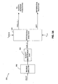
- FIG. 1 illustrates one embodiment of a wireless communication system 20, wherein system 20 is a spread spectrum CDMA system capable of voice and data transmissions.
- System 20 includes two segments: a wired subsystem and a wireless subsystem.
- the wired subsystem is the Public Switched Telephone Network, PSTN 26, and the Internet 22.
- the Internet 22 portion of the wired subsystem interfaces with the wireless subsystem via Inter-Working Function Internet, IWF 24.
- IWF 24 Inter-Working Function
- the wired subsystem may include but is not limited to other modules such as an instrumentation unit, a video unit, etc.
- the wireless subsystem includes the base station subsystem, which involves the Mobile Switching Center, MSC 28, the Base Station Controller, BSC 30, the Base Transceiver Station(s), BTS(s) 32, 34, and the Mobile Station(s), MS(s) 36, 38.
- the MSC 28 is the interface between the wireless subsystem and the wired subsystem. It is a switch that talks to a variety of wireless apparatus.
- the BSC 30 is the control and management system for one or more BTS(s) 32, 34. The BSC 30 exchanges messages with the BTS(s) 32, 34 and the MSC 28.
- Each of the BTS(s) 32, 34 consist of one or more transceivers placed at a single location. Each of the BTS(s) 32, 34 terminates the radio path on the network side.
- the BTS(s) 32, 34 may be in co-located with BSC 30 or may be independently located.
- the system 20 includes radio air interface physical channels 40, 42 between the BTS(s) 32, 34 and the MS(s) 36, 38.
- the physical channels 40, 42 are communication paths described in terms of the digital coding and RF characteristics.
- a FL is defined as a communication link for transmissions from one of the BTS(s) 32, 34 to one of the MS(s) 36, 38.
- An RL is defined as a communication link for transmissions from one of the MS(s) 36, 38 to one of the BTS(s) 32, 34.
- power control within system 20 includes controlling transmit power for both the RL and the FL. Multiple power control mechanisms may be applied to the FL and RL in system 20, including reverse open loop power control, reverse closed loop power control, forward closed loop power control, etc. Reverse open loop power control adjusts the initial access channel transmission power of MS(s) 36, 38, and compensates for variations in path loss attenuation of the RL.
- the RL uses two types of code channels: traffic channel(s), and access channel(s).
- FIG. 2 illustrates the architecture of a RL of system 20 of FIG. 1 according to one embodiment.
- the RL or reverse channel is composed of two types of logical channels: access and traffic.
- Each logical channel is a communication path within the protocol layers of either the BTS(s) 32, 34 or the MS(s) 36, 38.
- Information is grouped onto a logical channel based upon criteria such as the number of users, the transmission type, the direction of the transfer, etc.
- the information on a logical channel is ultimately carried on one or more physical channels. Mappings are defined between logical and physical channels. These mappings may be permanent or may be defined only for the duration of a given communication.
- a remote station may be, referred to as an Access Terminal; AT, wherein an AT is a device providing data connectivity to a user.
- An AT may be connected to a computing device, such as a laptop personal computer, or it may be a self-contained data device, such as a personal digital assistant.
- the base station may be referred to as an Access Network, AN, wherein the AN is network equipment providing data connectivity between a packet switched data network, such as the Internet, and at least one AT.
- the reverse access channel is used by ATs to communicate with the AN when no traffic channel is assigned. In one embodiment there is a separate reverse access channel for each sector of the AN.
- the traffic channel is composed of three logical channels: differential indicator; link quality indicator; and data.
- the link quality indicator provides a measure of the quality of the FL pilot channel.
- One embodiment uses Carrier-to-Interference, C/I, as a link quality metric, wherein the remote station measures the C/I of the FL pilot channel for multiple instances having a predetermined period.
- the link quality indicator is encoded for periodic transmission to the base station on the RL.
- the encoding may include the application of a cover, wherein the specific cover applied corresponds to the sector of the measured pilot signal.
- the encoded link quality indicator is referred to as a "quality message.” Alternate embodiments may implement other means of determining a link quality indicator and may implement other metrics corresponding to link quality. Additionally, the quality metric measurements may be applied to other received signals.
- the C/I measurement is often expressed in dB units.
- the link quality message is determined and transmitted periodically with relatively low latency to reduce any impact on available bandwidth on the RL.
- the link quality message is transmitted once every 20msec.
- a differential indicator is transmitted to the base station on the RL when the link quality indicator is not transmitted.
- the differential indicator is sent ever 1.25 msec.
- the traffic channel further includes the differential indicator sub-channel.
- the differential indicator is an indication of relative changes in the quality of the FL pilot channel, which is sent much more frequently.
- a comparison is made of successive C/I measurements of the FL pilot signal. The result of the comparison is transmitted as a bit or bits indicating the direction of the change.
- the differential indicator for an increase in successive C/I measurements the differential indicator is positive, and for a decrease in successive C/I measurements the differential indicator is negative.
- the differential indicator is transmitted with little or no coding, and therefore provides a fast, efficient, low latency feedback method.
- the differential indicator effectively provides continuous fast feedback to the base station regarding the state of the FL.
- the feedback is sent via the RL. Note that in contrast to power control commands which typically have an opposite polarity to the C/I measurement, the quality message and the differential indicator track the C/I measurement.
- the use of a differential indicator eliminates the need to transmit the entire C/I, wherein the differential indicator provides incremental comparisons to the last projected value.
- the differential indicator according to one embodiment is an UP (+1dB) or DOWN (-1dB) indicator. According to an alternate embodiment, successive steps in a same direction have increasing values, such as first UP (+1dB), second UP (+2dB), etc.
- the differential indicator includes multiple bits, wherein the bits have significance to identify the direction and amount of change. Since the fading channel is a continuous process, the C/I will be a continuous process and can therefore be tracked with such a differential signaling technique.
- This differential message is much smaller than the full C/I message, not only does it take less time to encode, to transmit, and to decode, but it also takes up less energy on the reverse link. This means that not only is the FL performance improved, but the RL loading is also reduced.
- the periodic transmission of a quality message prevents and/or corrects synchronization problems between the base station and remote station. For example, consider a remote station having an initial quality message corresponding to 0dB C/I measurement. The remote station continuously measures the link quality and proceeds to transmit three differential indicators, each corresponding to 1 dB increments. Thus, the remote station has calculated a projected C/I of 3dB. The base station may decode two of the differential indicators correctly, and have a decode error on a third.
- the base station has, therefore, calculated a projected C/I of 2dB.
- the remote station and the base station are out of synchronization.
- the next transmission of the encoded quality message is transmitted in a reliable manner and will correct the synchronization disparity.
- the quality message re-synchronizes the base station and the remote station.
- the quality message is encoded using a very powerful (5, 24) block code, interleaved, and transmitted over 20 ms. Note that the quality message is used to correct any synchronization errors that could have occurred in feeding back the differential indicators, and therefore, the quality message can tolerate relatively large latencies, such as 20 ms.
- the differential indicator is applicable in wireless communication systems using fast link adaptation techniques that require the receiver to constantly feedback the latest channel state to the transmitter. While the differential indicator is also applicable for feedback on FL of the RL channel state, in data services, link adaptation typically occurs on the forward link, and therefore the exemplary embodiment illustrates a remote station feeding information to the base station about the state of the FL using differential indicators on the RL. Ideally link quality feedback occurs frequently with minimum delay to maximize FL system performance. The use of a differential indicator reduces loading on the RL, thereby increasing the capacity of the RL available for data traffic.
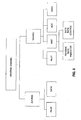
- the remote station 200 includes receive circuitry 202 that includes but is not limited to an antenna(s), and pre-processing filtering.
- the receive circuitry 202 processes signals received at the remote station 200 on the FL, including but not limited to the pilot signal.
- the receive circuitry 202 is coupled to quality measurement unit 204 that determines the quality metric measurement of the pilot signal.
- the quality measurement unit 204 measures the C/I of the received FL pilot signal.
- the quality metric measurement, cur_C_I is provided to differential analyzer 206.
- the differential analyzer 206 is responsive to a predetermined quality message period, T MESSAGE .
- the differential analyzer 206 provides one projected C/I measurement, proj_C_I, as a link quality indicator for further processing to form the quality message.
- the further processing includes encoding the link quality indicator, including application of a cover identifying the transmission sector of the measured pilot signal.
- the quality measurement unit 204 provides successive C/I measurements to the differential analyzer 206.
- each generated differential indicator is referred to as "diff." Note that the quality message and the differential indicator are generated at different rates. As illustrated in FIG. 3A, the differential analyzer 206 also receives an input signal, T DIFF , controlling the rate of differential indicator generation.
- the differential analyzer 206 process starts by receiving a C/I measurement from the quality measurement unit 204, wherein the cur_C_I is a link quality measure of a received signal.
- the process also stores the cur_C_I value as a projected measurement in a variable "proj_C_I" at step 302.
- Step 302 is an initialization step an is performed only once per session. At this point no historical C/I measurements are available for a comparison.
- the proj_C_l value is transmitted as the quality message.
- the C/I is measured and stored as a current measurement in a variable "cur_C_l" to be used for incremental differential comparisons.
- the differential analyzer 206 compares cur_C_I to proj_C_I and generates DIFF accordingly. Additionally, the variable proj_C_I is adjusted in accordance with the comparison at step 310. The adjustment tracks changes in the link quality and, therefore, if cur C_I is greater than proj_C_l, the value proj_C_l is increased and vice versa.
- the differential indicator, DIFF is transmitted at step 312, wherein DIFF has been determined by the comparison of cur_C_I and proj_C_I.
- DIFF provides an indication of the direction of change in link quality.
- DIFF is a single bit, wherein a positive value corresponds to an increase and a negative value corresponds to a decrease.
- Alternate polarity schemes may be implemented as well as multiple bits to represent DIFF, which provides an indication of the amount of change in addition to the direction of the change.
- each differential indicator is assumed to correspond to a predetermined step size. In an alternate embodiment the differential indicator is assumed to correspond to one of several predetermined step sizes. In another embodiment the amplitude of the differential indicator determines the step size. In another embodiment the differential indicator includes multiple information bits, wherein the bits have significance to select the direction and amplitude of the step size among a set of predetermined step sizes. In yet another alternate embodiment, the step size may change dynamically.
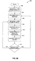
- FIG. 3C illustrates a method 350 for processing quality messages and differential indicators at a base station.
- a variable "QUALITY1" is initialized to a default value at step 352 with the first received quality message. The default value may be based on an initially received quality message.
- the process determines if a quality message is received at step 354. On receipt of a quality message, QUALITY1 is updated based on the quality message received at step 360. The process then returns to step 354. When no quality message has been received and a DIFF is received at step 356, the process continues to step 358 where QUALITY1 is adjusted based on DIFF. The process then returns to step 354.
- the quality message is transmitted on a gated channel, wherein transmissions are made once each time period T message .
- Differential indicators are transmitted at a higher frequency on a continuous channel.
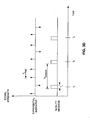
- a diagram of the signal strength of quality messages and the differential indicators are plotted as a function of time, as illustrated in FIG. 3D.
- the quality messages are transmitted at times t 1 , t 2 , t 3 , etc., wherein no quality messages are transmitted at other times within each period T message .
- the differential indicators are transmitted continuously.
- the quality message is transmitted for predetermined time duration T 1 .
- the differential indicators are separated by time duration T 2 . Ideally T 2 is greater than T 1 , wherein no differential indicator is transmitted within the time duration T 1 for transmission of the quality message.
- the base station does not receive a differential indicator and a quality message at a same given time.
- the base station uses the quality message.
- the quality messages and the differential indicators provide feedback to the base station. While FIG. 3D illustrates distinct and separate occurrences of quality messages and differential indicators, the quality message may be sent over a longer time period creating overlap between transmissions.
- the quality message may be encoded and transmitted, wherein the C/I messages are processed very slowly.
- the quality message would then be received and decoded at the base station much later.
- the base station effectively pipelines the differential indicators and is able to back out of a calculation path and return to find the projected measurement at the time when the message was encoded and transmitted by the remote station. If the base station finds that the quality message shows an incorrect calculation, i.e., result after application of differential indicators, the result is adjusted according to the quality message. For example, where the projected measurement was off by +2 dB, then the current projected measurement could be increased by 2 dB.
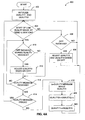
- FIG. 4A illustrates an alternate method 400 of processing received quality messages and differential indicators at a base station, wherein overlap may occur between quality messages and differential indicators.
- Two variables, QUALITY1 and QUALITY2 are initialized at step 402 with the first received quality message.
- QUALITY1 and QUALITY2 are initialized at step 402 with the first received quality message.
- the value stored in QUALITY1 at the start of the link quality measurement at the mobile station is maintained without change until the quality message is completely received. This allows adjustment for any DIFF(s) received during the quality message.
- the process 400 determines if receipt of a link quality measurement has started at step 404.
- the base station has a priori knowledge of the scheduling of link quality measurements at the remote station.
- step 406 determines if a DIFF has been received. If no DIFF is received processing returns to step 404, else QUALITY 1 and QUALITY 2 are adjusted based on DIFF at step 408 and then processing returns to step 404. Additionally at step 408, the QUALITY2 value is provided to a scheduler for implementation of a schedule of transmissions. From step 404, if a quality message has started, step 410 determines if a DIFF is received during a quality message, i.e., a DIFF and a quality message are both being received at the same time by the base station. If no DIFF is received during the quality message, the process continues to step 414 to determine if the quality message is complete.
- QUALITY2 is adjusted based on DIFF AT STEP 412. Additionally at step 412, the QUALITY2 value is provided to a scheduler for implementation of a schedule of transmissions. If the quality message is not complete at step 414, processing returns to step 410, else, the difference between the received quality message and QUALITY1 is set equal to DELTA, ⁇ at step 416.
- the DELTA is used to correct the link quality calculations at the base station. As the quality message was transmitted from the remote station prior to DIFF values received during receipt of the quality message at the base station, the DELTA allows application of these DIFF values to the corrected value.
- QUALITY2 is adjusted by DELTA at step 418 to correct the result of processing the DIFF(s) received during receipt of the quality message. Additionally at step 418, the QUALITY2 value is provided to a scheduler for implementation of a schedule of transmissions. At step 420, QUALITY1 is set equal to QUALITY2 and the synchronization is completed. Processing then returns to step 404.
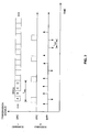
- FIGs. 4B and 4C illustrate, in timing diagram form, the receipt at a base station of the quality message and DIFF(s).
- the values of QUALITY1 and QUALITY2 are equal to A.
- the quality message receipt begins at time t 1 .
- DIFF(s) are then received at times t 2 through t 6 , with values indicated in the table of FIG. 4C. Note that for each DIFF received, the QUALITY2 value is adjusted accordingly, while QUALITY1 remains unchanged.
- the quality message completes and sets QUALITY1 equal to B.
- the value B is the quality message value transmitted from the remote station at or prior to time t 1 .
- the variable QUALITY2 is then adjusted according to the difference (B-A). This difference is added to the value of QUALITY2 at time t 8 . In this way, the base station has a corrected value of QUALITY2.
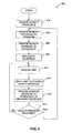
- FIG. 5 illustrates a method 600 used in one embodiment for processing the feedback information at the base station.
- the base station receives the quality message from the mobile station, wherein the quality message relates to the FL pilot signal strength.
- the quality message received is stored in a memory storage device at step 604.
- the base station provides the quality message received to a scheduler at step 606.
- the scheduler is responsible for providing fair and proportional access to the base station from all access terminals having data to transmit and/or receive.
- the scheduling of access terminals may be performed in any of a variety of methods.
- the scheduler then implements the schedule at step 608.
- the base station receives a differential indicator, DIFF, at step 610.
- DIFF differential indicator
- the base station applies the differential indicator to the stored quality message at step 612 to track the quality of the FL channel. In this way the base station is aprised of the condition and quality of the FL channel as seen at the receiver of the access terminal.
- the process provides the quality message to the scheduler to implement a schedule at step 614. The process determines if a quality message is received at step 616.
- processing returns to receive the next differential indicator at step 610.
- a quality message is received at step 616 the process returns to step 604 to store the quality message in memory.
- the stored quality message is adjusted with each occurrence of a differential indicator.
- the stored quality message is replaced on the occurrence of a quality message.
- Link quality feedback methods are applicable to packet-switched communication systems, such as data and voice systems.
- a packet-switched system the data is transmitted in packets having a defined structure and length. Rather than using power control to adjust the amplification of transmissions, these systems adjust the data rate and modulation scheme in response to the quality of the link.
- the available transmit power for data transmissions is not defined or controlled, but rather is dynamically calculated as the remaining power available after satisfaction of voice transmissions.
- An exemplary system having a reverse link illustrated in FIG. 6 uses a data rate control and an additional sub-channel to transmit quality messages and differential indicators, respectively. As illustrated, the reverse link, or reverse channel, has two types of logical channels: access and traffic.
- the access channel includes sub-channels for a pilot and data, wherein the access channel is used while the traffic channel is not active.
- the traffic channel includes sub-channels for pilot, Medium Access Control, MAC, Acknowledge, ACK, and data.
- the MAC further includes sub-channels for transmission of reverse rate indicator(s) and Data Rate Control(s), DRC(s).
- the DRC information is calculated by the remote station or access terminal by measuring the quality of the FL and requesting a corresponding data rate for receipt of pending data transmissions. There are any number of methods for calculating the quality of the link, and determining a corresponding data rate.
- the differential indicators are transmitted continuously on the reverse rate indicator channel, while the quality messages are transmitted on a DRC channel.
- the corresponding data rate is typically determined by a table that identifies the available and/or appropriate data rate, modulation and encoding, packet structure, and retransmission policy.
- the DRC messages are indices identifying the appropriate combination of specifications. In response to a link quality measurement, an increase in the data rate available increments the index. A decrease in the data rate available decrements the index.
- the DRC message is encoded prior to transmission. A DRC cover is applied to identify the sector of the measured FL signal, typically the FL pilot.
- DRC(i) is a four slot message, wherein the message DRC(i) is transmitted in time slots A, B, C and D.
- the four slot message is transmitted during time duration T DRC .
- DRC(i+1) will be transmitted.
- DRC(i-1) Prior to time slot A the previous message, DRC(i-1) was transmitted.
- the quality message is implicitly included in the DRC message and is transmitted continuously. This scenario wastes bandwidth and thus reduces the capacity of the reverse link.
- the DRC message is transmitted on a gated channel, the DRC channel, once during T DRC .
- the differential indicator is transmitted on a continuous sub-channel having a period of T diff .
- the differential indicator either increments or decrements the index of the DRC message.
- the access network is able to accurately track the available data rates, etc., quickly, as the differential indicator is an uncoded bit or bit(s). Note that while the quality message and differential indicator have been described herein with respect to the FL, each is applicable to the RL as well.
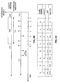
- FIG. 8 illustrates a data rate control table according to one embodiment.
- the left-most column lists a DRC message.
- the DRC message is effectively a code that identifies a combination of transmission parameters.
- the middle column corresponds to the data rate in kbps.
- the last column lists the packet length in time slots.
- Each DRC message corresponds to a combination of these transmission parameters and may also include, but is not limited to, modulation technique, encoding type, packet structure, and/or retransmission policy.
- the first DRC message selects a null data rate.
- the null data rate is used in other processes within the system.
- several DRC messages corresponds to transmission parameter sets that are not available or are invalid. These sets may be assigned to later developed systems or may be used for other functions within the system.
- the quality message is included in the preamble of each transmission.
- the differential indicators are transmitted on a continuous sub-channel.
- the differential indicators are provided at a frequency to assist the transmitter in accurately tracking the channel quality experienced by transmitted communications.
- a portion 500 of an access terminal includes a DRC table 502, coupled to a DRC calculation unit.504.
- the DRC calculation unit 504 receives a FL signal within the packet-switched system.
- the DRC calculation unit 504 analyzes the received signal to determine a channel quality metric.
- the quality metric is a data rate.
- the DRC calculation unit 504 selects a transmission parameter set from the DRC table 502, wherein the set corresponds to the calculated data rate available for the FL. The set is identified by a corresponding DRC message.
- the DRC calculation unit 504 provides a measured DRC to differential analyzer 506.
- the differential analyzer 506 generates the projected DRC message for full transmission once every DRC time period, T DRC .
- the full projected DRC message transmission is gated according to T DRC .
- the differential analyzer 506 receives a differential time period signal, T DIFF , that is used to generate differential indicators.
- the differential analyzer 506 outputs a differential indicator in response to the comparison.
- the differential indicator is an incremental pointer that points to neighboring entries in the DRC table 502. If a successive DRC message increments from a previous DRC message in a given direction, the differential indicator points in that direction.
- the differential indicator therefore, tracks movement within the DRC table 502. In this way, the FL transmitter receives continuous information of FL channel quality with which transmission parameters may be evaluated and/or adjusted.
- the feedback information is applicable to scheduling of packet-switched communications in the system.
- the periodic DRC message transmissions provide synchronization between FL transmitter and receiver, erroneous information generated by incorrectly received differential indicators.
- the differential indicators in a packet-switched system provide feedback that may effect more than simply the remote station generating the feedback.
- the access network may use the feedback information to determine a scheduling policy, as well as implementing the policy, for multiple users. In this way, the feedback information may be used to optimize the entire transmission system.
- the periodic transmission of the quality message allows synchronization of the remote station and the base station.
- the base station transmits a projected C/l as calculated at the base station on the FL.
- the remote station receives the projected C/I from the base station and re-synchronizes with the base station.
- the transmission may be a coded message or a signal transmitted at a predetermined power level.
- the transmission may be a dedicated pilot or a PC bit.
- the remote station may indicate the sector that is currently being monitored by applying a cover or a scrambling code to the quality message and/or differential indicator.
- the cover identifies the sector of the measured pilot signal.
- each sector in the system is assigned a scrambling code.
- the scrambling code is a priori knowledge to the base station and the remote station.
- DSP digital signal processor
- ASIC application specific integrated circuit
- FPGA field programmable gate array
- a general-purpose processor may be a microprocessor, but in the alternative, the processor may be any conventional processor, controller, microcontroller, or state machine.
- a processor may also be implemented as a combination of computing devices, e.g., a combination of a DSP and a microprocessor, a plurality of microprocessors, one or more microprocessors in conjunction with a DSP core, or any other such configuration.
- a software module may reside in RAM memory, flash memory, ROM memory, EPROM memory, EEPROM memory, registers, hard disk, a removable disk, a CD-ROM, or any other form of storage medium known in the art.
- An exemplary storage medium is coupled to the processor such the processor can read information from, and write information to, the storage medium.
- the storage medium may be integral to the processor.
- the processor and the storage medium may reside in an ASIC.
- the ASIC may reside in a user terminal.
- the processor and the storage medium may reside as discrete components in a user terminal.
Priority Applications (1)
| Application Number | Priority Date | Filing Date | Title |
|---|---|---|---|
| EP10009797.1A EP2256945B1 (fr) | 2001-02-15 | 2002-01-23 | Procédé et appareil pour le retour de la qualité de la liaison dans un système de communication sans fil |
Applications Claiming Priority (2)
| Application Number | Priority Date | Filing Date | Title |
|---|---|---|---|
| US09/784,807 US6985453B2 (en) | 2001-02-15 | 2001-02-15 | Method and apparatus for link quality feedback in a wireless communication system |
| EP02714785A EP1360778B1 (fr) | 2001-02-15 | 2002-01-23 | Procede et appareil destines a une retroaction de la qualite de la liaison dans une communication sans fil |
Related Parent Applications (2)
| Application Number | Title | Priority Date | Filing Date |
|---|---|---|---|
| EP02714785.9 Division | 2002-01-23 | ||
| EP02714785A Division EP1360778B1 (fr) | 2001-02-15 | 2002-01-23 | Procede et appareil destines a une retroaction de la qualite de la liaison dans une communication sans fil |
Related Child Applications (2)
| Application Number | Title | Priority Date | Filing Date |
|---|---|---|---|
| EP10009797.1A Division EP2256945B1 (fr) | 2001-02-15 | 2002-01-23 | Procédé et appareil pour le retour de la qualité de la liaison dans un système de communication sans fil |
| EP10009797.1 Division-Into | 2010-09-17 |
Publications (3)
| Publication Number | Publication Date |
|---|---|
| EP1801997A2 true EP1801997A2 (fr) | 2007-06-27 |
| EP1801997A3 EP1801997A3 (fr) | 2007-07-18 |
| EP1801997B1 EP1801997B1 (fr) | 2012-04-18 |
Family
ID=25133591
Family Applications (3)
| Application Number | Title | Priority Date | Filing Date |
|---|---|---|---|
| EP10009797.1A Expired - Lifetime EP2256945B1 (fr) | 2001-02-15 | 2002-01-23 | Procédé et appareil pour le retour de la qualité de la liaison dans un système de communication sans fil |
| EP07007459A Expired - Lifetime EP1801997B1 (fr) | 2001-02-15 | 2002-01-23 | Procédé et appareil pour le retour de la qualité de la liaison dans un système de communication sans fil |
| EP02714785A Expired - Lifetime EP1360778B1 (fr) | 2001-02-15 | 2002-01-23 | Procede et appareil destines a une retroaction de la qualite de la liaison dans une communication sans fil |
Family Applications Before (1)
| Application Number | Title | Priority Date | Filing Date |
|---|---|---|---|
| EP10009797.1A Expired - Lifetime EP2256945B1 (fr) | 2001-02-15 | 2002-01-23 | Procédé et appareil pour le retour de la qualité de la liaison dans un système de communication sans fil |
Family Applications After (1)
| Application Number | Title | Priority Date | Filing Date |
|---|---|---|---|
| EP02714785A Expired - Lifetime EP1360778B1 (fr) | 2001-02-15 | 2002-01-23 | Procede et appareil destines a une retroaction de la qualite de la liaison dans une communication sans fil |
Country Status (21)
| Country | Link |
|---|---|
| US (1) | US6985453B2 (fr) |
| EP (3) | EP2256945B1 (fr) |
| JP (4) | JP2004531114A (fr) |
| KR (2) | KR100933513B1 (fr) |
| CN (3) | CN1531786B (fr) |
| AT (2) | ATE366003T1 (fr) |
| AU (2) | AU2002247030B8 (fr) |
| BR (1) | BRPI0207875B1 (fr) |
| CA (1) | CA2438440C (fr) |
| DE (1) | DE60220881T2 (fr) |
| DK (1) | DK1801997T3 (fr) |
| ES (2) | ES2383140T3 (fr) |
| HK (2) | HK1104696A1 (fr) |
| IL (3) | IL157405A0 (fr) |
| MX (1) | MXPA03007362A (fr) |
| NO (2) | NO329818B1 (fr) |
| PT (1) | PT1801997E (fr) |
| RU (1) | RU2285338C2 (fr) |
| TW (1) | TW535371B (fr) |
| UA (1) | UA74416C2 (fr) |
| WO (1) | WO2002067461A1 (fr) |
Cited By (1)
| Publication number | Priority date | Publication date | Assignee | Title |
|---|---|---|---|---|
| US7986672B2 (en) * | 2002-02-25 | 2011-07-26 | Qualcomm Incorporated | Method and apparatus for channel quality feedback in a wireless communication |
Families Citing this family (105)
| Publication number | Priority date | Publication date | Assignee | Title |
|---|---|---|---|---|
| US9130810B2 (en) * | 2000-09-13 | 2015-09-08 | Qualcomm Incorporated | OFDM communications methods and apparatus |
| US7295509B2 (en) | 2000-09-13 | 2007-11-13 | Qualcomm, Incorporated | Signaling method in an OFDM multiple access system |
| US6985453B2 (en) * | 2001-02-15 | 2006-01-10 | Qualcomm Incorporated | Method and apparatus for link quality feedback in a wireless communication system |
| US7023810B1 (en) | 2001-03-21 | 2006-04-04 | Cisco Technology, Inc. | Decoding using redundant packet selection information in wireless communications systems |
| US7103019B1 (en) | 2001-03-21 | 2006-09-05 | Cisco Technology, Inc. | Error correction using redundant packet streams in wireless communications systems |
| US6944123B1 (en) * | 2001-03-21 | 2005-09-13 | Cisco Technology, Inc. | Redundant packet selection and manipulation in wireless communications systems |
| AU2006252118B8 (en) * | 2001-05-14 | 2010-03-04 | Interdigital Technology Corporation | Channel quality measurements for downlink resource allocation |
| KR101069304B1 (ko) | 2001-05-14 | 2011-10-05 | 인터디지탈 테크날러지 코포레이션 | 다운링크 자원 할당을 위한 채널 품질 측정값 제공 방법, 무선 디지털 통신 시스템 및 사용자 장치 |
| WO2003021903A1 (fr) * | 2001-08-28 | 2003-03-13 | Sony Corporation | Emetteur et procede de commande d'emissions |
| KR100498922B1 (ko) * | 2001-08-31 | 2005-07-04 | 삼성전자주식회사 | 이동통신 시스템에서 순방향 채널의 품질정보 송수신방법및 장치 |
| US7756082B1 (en) | 2001-09-07 | 2010-07-13 | Atheros Communications, Inc. | Wireless LAN using background scanning technique |
| KR100493079B1 (ko) * | 2001-11-02 | 2005-06-02 | 삼성전자주식회사 | 고속 순방향 패킷 접속 방식을 사용하는 광대역 부호 분할다중 접속 통신 시스템에서 순방향 채널 품질을 보고하는장치 및 방법 |
| US7787530B2 (en) * | 2001-12-28 | 2010-08-31 | Alcatel-Lucent Usa Inc. | Multi-channel adapative quality control loop for link rate adaptation in data packet communications |
| US8364159B2 (en) * | 2002-02-11 | 2013-01-29 | Qualcomm Incorporated | Method and apparatus for monitoring a channel during an active session in a wireless communication system |
| US7050759B2 (en) * | 2002-02-19 | 2006-05-23 | Qualcomm Incorporated | Channel quality feedback mechanism and method |
| US7463616B1 (en) * | 2002-03-28 | 2008-12-09 | Nortel Networks Limited | Scheduling based on channel change indicia |
| GB2388745A (en) * | 2002-04-30 | 2003-11-19 | Hewlett Packard Co | Mobile communication system with service quality feedback |
| US7369510B1 (en) | 2002-05-06 | 2008-05-06 | Atheros Communications, Inc. | Wireless LAN using RSSI and BER parameters for transmission rate adaptation |
| US7463599B2 (en) * | 2002-05-17 | 2008-12-09 | Telefonaktiebolaget L M Ericsson (Publ) | Method and apparatus for minimizing time of reception during paging |
| US7342912B1 (en) * | 2002-06-28 | 2008-03-11 | Arraycomm, Llc. | Selection of user-specific transmission parameters for optimization of transmit performance in wireless communications using a common pilot channel |
| US7209712B2 (en) | 2002-09-23 | 2007-04-24 | Qualcomm, Incorporated | Mean square estimation of channel quality measure |
| US7424270B2 (en) * | 2002-09-25 | 2008-09-09 | Qualcomm Incorporated | Feedback decoding techniques in a wireless communications system |
| KR100950652B1 (ko) * | 2003-01-08 | 2010-04-01 | 삼성전자주식회사 | 직교 주파수 분할 다중 전송 방식에서 순방향 링크의 채널 상태 추정 방법 |
| US7751337B2 (en) * | 2003-02-10 | 2010-07-06 | The Boeing Company | Method and apparatus for optimizing forward link data rate for radio frequency transmissions to mobile platforms |
| DE60323047D1 (de) * | 2003-03-21 | 2008-10-02 | Ericsson Telefon Ab L M | Verfahren und Vorrichtung zur Verbindungsanpassung |
| WO2004084452A2 (fr) * | 2003-03-21 | 2004-09-30 | Telefonaktiebolaget L M Ericsson (Publ) | Procede et appareil d'adaptation de liaison |
| JP3638942B2 (ja) * | 2003-04-17 | 2005-04-13 | シャープ株式会社 | 表示装置、無線通信システム、表示装置の制御方法、無線通信システムの制御方法、表示装置制御プログラム、無線通信システム制御プログラム、および該プログラムを記録した記録媒体 |
| US7640373B2 (en) * | 2003-04-25 | 2009-12-29 | Motorola, Inc. | Method and apparatus for channel quality feedback within a communication system |
| DE10320156A1 (de) * | 2003-05-06 | 2004-12-16 | Siemens Ag | Verfahren zur Datenübertragung |
| US7593363B2 (en) | 2003-05-06 | 2009-09-22 | Nokia Siemens Networks Gmbh & Co. Kg | Data transmission method |
| KR20060018882A (ko) * | 2003-06-06 | 2006-03-02 | 메시네트웍스, 인코포레이티드 | 애드혹 무선 네트워크에서 라우팅 프로토콜에 링크신뢰도의 척도를 제공하기 위한 방법 |
| JP4069034B2 (ja) * | 2003-07-31 | 2008-03-26 | 松下電器産業株式会社 | 無線送信装置、無線受信装置、無線通信システム、無線送信方法及び無線受信方法 |
| GB0326365D0 (en) | 2003-11-12 | 2003-12-17 | Koninkl Philips Electronics Nv | A radio communication system,a method of operating a communication system,and a mobile station |
| KR100946923B1 (ko) * | 2004-03-12 | 2010-03-09 | 삼성전자주식회사 | 직교 주파수 분할 다중 방식을 사용하는 통신 시스템에서 채널 품질 정보의 송수신 장치 및 방법, 그리고 그에 따른 시스템 |
| US20050254508A1 (en) * | 2004-05-13 | 2005-11-17 | Nokia Corporation | Cooperation between packetized data bit-rate adaptation and data packet re-transmission |
| US9137822B2 (en) | 2004-07-21 | 2015-09-15 | Qualcomm Incorporated | Efficient signaling over access channel |
| US9148256B2 (en) * | 2004-07-21 | 2015-09-29 | Qualcomm Incorporated | Performance based rank prediction for MIMO design |
| US7668085B2 (en) * | 2004-08-27 | 2010-02-23 | Telefonaktiebolaget Lm Ericsson (Publ) | Common rate control command generation |
| US7499452B2 (en) * | 2004-12-28 | 2009-03-03 | International Business Machines Corporation | Self-healing link sequence counts within a circular buffer |
| US8363604B2 (en) * | 2005-02-01 | 2013-01-29 | Qualcomm Incorporated | Method and apparatus for controlling a transmission data rate based on feedback relating to channel conditions |
| US9246560B2 (en) * | 2005-03-10 | 2016-01-26 | Qualcomm Incorporated | Systems and methods for beamforming and rate control in a multi-input multi-output communication systems |
| US20060203794A1 (en) * | 2005-03-10 | 2006-09-14 | Qualcomm Incorporated | Systems and methods for beamforming in multi-input multi-output communication systems |
| US9154211B2 (en) | 2005-03-11 | 2015-10-06 | Qualcomm Incorporated | Systems and methods for beamforming feedback in multi antenna communication systems |
| US8446892B2 (en) * | 2005-03-16 | 2013-05-21 | Qualcomm Incorporated | Channel structures for a quasi-orthogonal multiple-access communication system |
| US20090213950A1 (en) * | 2005-03-17 | 2009-08-27 | Qualcomm Incorporated | Pilot signal transmission for an orthogonal frequency division wireless communication system |
| US9520972B2 (en) * | 2005-03-17 | 2016-12-13 | Qualcomm Incorporated | Pilot signal transmission for an orthogonal frequency division wireless communication system |
| US9461859B2 (en) * | 2005-03-17 | 2016-10-04 | Qualcomm Incorporated | Pilot signal transmission for an orthogonal frequency division wireless communication system |
| US9143305B2 (en) * | 2005-03-17 | 2015-09-22 | Qualcomm Incorporated | Pilot signal transmission for an orthogonal frequency division wireless communication system |
| US9184870B2 (en) * | 2005-04-01 | 2015-11-10 | Qualcomm Incorporated | Systems and methods for control channel signaling |
| FI20055169A0 (fi) * | 2005-04-13 | 2005-04-13 | Nokia Corp | Pakettidatan siirron tehonsäätö matkapuhelinverkossa |
| US9408220B2 (en) * | 2005-04-19 | 2016-08-02 | Qualcomm Incorporated | Channel quality reporting for adaptive sectorization |
| US9036538B2 (en) * | 2005-04-19 | 2015-05-19 | Qualcomm Incorporated | Frequency hopping design for single carrier FDMA systems |
| US8611284B2 (en) * | 2005-05-31 | 2013-12-17 | Qualcomm Incorporated | Use of supplemental assignments to decrement resources |
| US8565194B2 (en) * | 2005-10-27 | 2013-10-22 | Qualcomm Incorporated | Puncturing signaling channel for a wireless communication system |
| US8879511B2 (en) * | 2005-10-27 | 2014-11-04 | Qualcomm Incorporated | Assignment acknowledgement for a wireless communication system |
| US8462859B2 (en) * | 2005-06-01 | 2013-06-11 | Qualcomm Incorporated | Sphere decoding apparatus |
| US9179319B2 (en) * | 2005-06-16 | 2015-11-03 | Qualcomm Incorporated | Adaptive sectorization in cellular systems |
| US8599945B2 (en) | 2005-06-16 | 2013-12-03 | Qualcomm Incorporated | Robust rank prediction for a MIMO system |
| DE102005029812A1 (de) * | 2005-06-27 | 2006-12-28 | Siemens Ag | Verfahren und Vorrichtung zur Optimierung der Linkadaption |
| US8838115B2 (en) * | 2005-07-20 | 2014-09-16 | Qualcomm Incorporated | Method and apparatus for expanded data rate control indices in a wireless communication system |
| US8885628B2 (en) | 2005-08-08 | 2014-11-11 | Qualcomm Incorporated | Code division multiplexing in a single-carrier frequency division multiple access system |
| US20070058603A1 (en) * | 2005-08-12 | 2007-03-15 | Samsung Electronics Co., Ltd. | Apparatus and method for estimating and reporting a carrier to interference noise ratio in a multi-antenna system |
| KR100770909B1 (ko) | 2005-08-12 | 2007-10-26 | 삼성전자주식회사 | 다중 안테나 시스템에서 수신 신호대 잡음 간섭비 추정 및보고 장치 및 방법 |
| PL1922841T3 (pl) * | 2005-08-16 | 2010-10-29 | Qualcomm Inc | Sposoby i systemy adaptacyjnego wyboru serwera w komunikacji bezprzewodowej |
| US20070041457A1 (en) * | 2005-08-22 | 2007-02-22 | Tamer Kadous | Method and apparatus for providing antenna diversity in a wireless communication system |
| US9209956B2 (en) * | 2005-08-22 | 2015-12-08 | Qualcomm Incorporated | Segment sensitive scheduling |
| EP2369761B1 (fr) | 2005-08-24 | 2020-11-25 | InterDigital Technology Corporation | Procédé et appareil pour régler la période de retour d'informations d'indicateurs de qualité de canal pour augmenter la capacité en liaison montante |
| US8644292B2 (en) | 2005-08-24 | 2014-02-04 | Qualcomm Incorporated | Varied transmission time intervals for wireless communication system |
| US20070047495A1 (en) * | 2005-08-29 | 2007-03-01 | Qualcomm Incorporated | Reverse link soft handoff in a wireless multiple-access communication system |
| US9136974B2 (en) | 2005-08-30 | 2015-09-15 | Qualcomm Incorporated | Precoding and SDMA support |
| EP2083529A3 (fr) * | 2005-10-21 | 2009-08-05 | Telefonaktiebolaget LM Ericsson (publ) | Rapport de mesures dans un système de télécommunication cellulaire |
| US9210651B2 (en) | 2005-10-27 | 2015-12-08 | Qualcomm Incorporated | Method and apparatus for bootstraping information in a communication system |
| US8582509B2 (en) * | 2005-10-27 | 2013-11-12 | Qualcomm Incorporated | Scalable frequency band operation in wireless communication systems |
| US9144060B2 (en) | 2005-10-27 | 2015-09-22 | Qualcomm Incorporated | Resource allocation for shared signaling channels |
| US8045512B2 (en) | 2005-10-27 | 2011-10-25 | Qualcomm Incorporated | Scalable frequency band operation in wireless communication systems |
| US8477684B2 (en) | 2005-10-27 | 2013-07-02 | Qualcomm Incorporated | Acknowledgement of control messages in a wireless communication system |
| US9225488B2 (en) | 2005-10-27 | 2015-12-29 | Qualcomm Incorporated | Shared signaling channel |
| US9088384B2 (en) * | 2005-10-27 | 2015-07-21 | Qualcomm Incorporated | Pilot symbol transmission in wireless communication systems |
| US9225416B2 (en) * | 2005-10-27 | 2015-12-29 | Qualcomm Incorporated | Varied signaling channels for a reverse link in a wireless communication system |
| US9172453B2 (en) * | 2005-10-27 | 2015-10-27 | Qualcomm Incorporated | Method and apparatus for pre-coding frequency division duplexing system |
| US8693405B2 (en) * | 2005-10-27 | 2014-04-08 | Qualcomm Incorporated | SDMA resource management |
| US8582548B2 (en) | 2005-11-18 | 2013-11-12 | Qualcomm Incorporated | Frequency division multiple access schemes for wireless communication |
| US8831607B2 (en) * | 2006-01-05 | 2014-09-09 | Qualcomm Incorporated | Reverse link other sector communication |
| KR100751509B1 (ko) * | 2006-03-06 | 2007-08-22 | 재단법인서울대학교산학협력재단 | 부분적 공유를 이용한 선택적 채널 피드백 시스템 및 방법 |
| US7864724B2 (en) | 2006-05-05 | 2011-01-04 | Nokia Corporation | Enhanced UE out-of-sync behavior with gated uplink DPCCH or gated downlink F-DPCH or DPCCH transmission |
| US7864802B1 (en) * | 2006-08-17 | 2011-01-04 | Sprint Communications Company L.P. | TCP-aware resource allocation in wireless networks |
| WO2008066432A1 (fr) * | 2006-11-30 | 2008-06-05 | Telefonaktiebolaget L M Ericsson (Publ) | Procédé et appareil permettant de réduire la charge de largeur de bande de signalisation en rapportant des mesures de manière différentielle dans un message de multidiffusion |
| US8437281B2 (en) * | 2007-03-27 | 2013-05-07 | Cisco Technology, Inc. | Distributed real-time data mixing for conferencing |
| US8078110B2 (en) * | 2007-07-09 | 2011-12-13 | Qualcomm Incorporated | Techniques for choosing and broadcasting receiver beamforming vectors in peer-to-peer (P2P) networks |
| JP5162184B2 (ja) * | 2007-08-14 | 2013-03-13 | 株式会社エヌ・ティ・ティ・ドコモ | ユーザ装置、基地局及びチャネル品質情報報告方法 |
| ES2373240T3 (es) | 2007-12-20 | 2012-02-01 | Panasonic Corporation | Señalización de canal de control usando un campo de señalización común para el formato de transporte y la versión de redundancia. |
| JP4893618B2 (ja) * | 2007-12-27 | 2012-03-07 | 富士通東芝モバイルコミュニケーションズ株式会社 | 移動無線端末装置および移動通信システム |
| EP3425982B1 (fr) * | 2008-03-19 | 2022-06-15 | Huawei Technologies Co., Ltd. | Appareil de station mobile, appareil de station de base, procédé de communication et système de communication |
| US20090274226A1 (en) * | 2008-05-05 | 2009-11-05 | Motorola, Inc. | Sounding channel based feedback in a wireless communication system |
| US8380531B2 (en) * | 2008-07-25 | 2013-02-19 | Invivodata, Inc. | Clinical trial endpoint development process |
| EP2182754B1 (fr) | 2008-10-30 | 2014-01-15 | Telefonaktiebolaget LM Ericsson (publ) | Procédé et récepteur pour estimer et rapporter une mesure de qualité de canal |
| US20100232384A1 (en) * | 2009-03-13 | 2010-09-16 | Qualcomm Incorporated | Channel estimation based upon user specific and common reference signals |
| ES2566974T3 (es) * | 2010-02-23 | 2016-04-18 | Alcatel Lucent | Realimentación de información de estado de canal |
| JP5561779B2 (ja) * | 2010-10-21 | 2014-07-30 | 日本電気株式会社 | 無線通信装置、送信電力制御方法およびプログラム |
| US8537875B2 (en) | 2011-04-14 | 2013-09-17 | Qualcomm Incorporated | Methods and apparatus for adjusting forward link signal to interference and noise ratio estimates |
| US9237467B2 (en) | 2013-11-27 | 2016-01-12 | At&T Intellectual Property I, L.P. | Adaptive pacing of media content delivery over a wireless network |
| JP7071290B2 (ja) * | 2016-06-03 | 2022-05-18 | テレフオンアクチーボラゲット エルエム エリクソン(パブル) | 5gスプリットベアラフロー制御の管理 |
| CN108809484B (zh) | 2017-04-28 | 2020-04-21 | 华为技术有限公司 | 一种信道状态的指示方法、装置及网络设备 |
| KR102240375B1 (ko) * | 2019-04-25 | 2021-04-13 | 전남대학교산학협력단 | 교정인자 결정 장치, 교정인자 결정 방법, 단말 및 이를 이용한 cqi 피드백 방법 |
| KR102226865B1 (ko) * | 2020-06-01 | 2021-03-10 | 전남대학교산학협력단 | 교정인자 결정 장치, 교정인자 결정 방법, 단말 및 이를 이용한 cqi 피드백 방법 |
Citations (1)
| Publication number | Priority date | Publication date | Assignee | Title |
|---|---|---|---|---|
| US5465398A (en) | 1993-10-07 | 1995-11-07 | Metricom, Inc. | Automatic power level control of a packet communication link |
Family Cites Families (21)
| Publication number | Priority date | Publication date | Assignee | Title |
|---|---|---|---|---|
| FR2718906B1 (fr) * | 1994-04-13 | 1996-05-24 | Alcatel Mobile Comm France | Procédé d'adaptation de l'interface air, dans un système de radiocommunication avec des mobiles, station de base, station mobile et mode de transmission correspondants. |
| JP2974274B2 (ja) * | 1994-05-12 | 1999-11-10 | エヌ・ティ・ティ移動通信網株式会社 | 送信電力制御方法および送信電力制御装置 |
| US5551057A (en) * | 1994-06-08 | 1996-08-27 | Lucent Technologies Inc. | Cellular mobile radio system power control |
| US5873028A (en) * | 1994-10-24 | 1999-02-16 | Ntt Mobile Communications Network Inc. | Transmission power control apparatus and method in a mobile communication system |
| US5710981A (en) * | 1995-05-23 | 1998-01-20 | Ericsson Inc. | Portable radio power control device and method using incrementally degraded received signals |
| US5726978A (en) * | 1995-06-22 | 1998-03-10 | Telefonaktiebolaget L M Ericsson Publ. | Adaptive channel allocation in a frequency division multiplexed system |
| US5771461A (en) * | 1996-06-28 | 1998-06-23 | Motorola, Inc. | Method and apparatus for power control of a first channel based on a signal quality of a second channel |
| US5893035A (en) * | 1996-09-16 | 1999-04-06 | Qualcomm Incorporated | Centralized forward link power control |
| AU688231B1 (en) * | 1997-03-12 | 1998-03-05 | Nokia Telecommunications Oy | Estimating CIR using correlation with line removal |
| DE19715934C1 (de) * | 1997-04-16 | 1999-06-17 | Siemens Ag | Verfahren und Anordnung zum Bestimmen der Übertragungsqualität eines Funkkanals |
| US6167031A (en) * | 1997-08-29 | 2000-12-26 | Telefonaktiebolaget Lm Ericsson (Publ) | Method for selecting a combination of modulation and channel coding schemes in a digital communication system |
| US6574211B2 (en) * | 1997-11-03 | 2003-06-03 | Qualcomm Incorporated | Method and apparatus for high rate packet data transmission |
| JP3397677B2 (ja) * | 1998-02-10 | 2003-04-21 | 松下電器産業株式会社 | 送信電力制御装置及び無線通信装置 |
| US6603773B2 (en) * | 1998-04-08 | 2003-08-05 | Nokia Mobile Phones Limited | Method and system for controlling the transmission power of certain parts of a radio transmission |
| US6137994A (en) * | 1998-05-29 | 2000-10-24 | Motorola, Inc. | Radio communication system and method for setting an output power of a base site therein |
| KR100262934B1 (ko) | 1998-06-11 | 2000-08-01 | 조정남 | 전파환경의 변화에 따른 전송율 가변 방법 |
| JP3127898B2 (ja) * | 1998-09-01 | 2001-01-29 | 日本電気株式会社 | ハンドオフ制御方式及びハンドオフ制御方法 |
| US6192040B1 (en) * | 1999-04-16 | 2001-02-20 | Motorola, Inc. | Method and apparatus for producing channel estimate of a communication channel in a CDMA communication system |
| US6385462B1 (en) * | 2000-05-26 | 2002-05-07 | Motorola, Inc. | Method and system for criterion based adaptive power allocation in a communication system with selective determination of modulation and coding |
| US6741862B2 (en) * | 2001-02-07 | 2004-05-25 | Airvana, Inc. | Enhanced reverse-link rate control in wireless communication |
| US6985453B2 (en) * | 2001-02-15 | 2006-01-10 | Qualcomm Incorporated | Method and apparatus for link quality feedback in a wireless communication system |
-
2001
- 2001-02-15 US US09/784,807 patent/US6985453B2/en not_active Expired - Lifetime
-
2002
- 2002-01-23 WO PCT/US2002/002142 patent/WO2002067461A1/fr active IP Right Grant
- 2002-01-23 UA UA2003087744A patent/UA74416C2/uk unknown
- 2002-01-23 EP EP10009797.1A patent/EP2256945B1/fr not_active Expired - Lifetime
- 2002-01-23 JP JP2002566870A patent/JP2004531114A/ja not_active Withdrawn
- 2002-01-23 DK DK07007459.6T patent/DK1801997T3/da active
- 2002-01-23 CN CN028072154A patent/CN1531786B/zh not_active Expired - Lifetime
- 2002-01-23 EP EP07007459A patent/EP1801997B1/fr not_active Expired - Lifetime
- 2002-01-23 BR BRPI0207875A patent/BRPI0207875B1/pt active IP Right Grant
- 2002-01-23 PT PT07007459T patent/PT1801997E/pt unknown
- 2002-01-23 IL IL15740502A patent/IL157405A0/xx unknown
- 2002-01-23 CN CN2007100044796A patent/CN101018088B/zh not_active Expired - Lifetime
- 2002-01-23 RU RU2003127724/09A patent/RU2285338C2/ru active
- 2002-01-23 EP EP02714785A patent/EP1360778B1/fr not_active Expired - Lifetime
- 2002-01-23 ES ES07007459T patent/ES2383140T3/es not_active Expired - Lifetime
- 2002-01-23 CA CA2438440A patent/CA2438440C/fr not_active Expired - Lifetime
- 2002-01-23 CN CN201410024885.9A patent/CN103813390B/zh not_active Expired - Lifetime
- 2002-01-23 KR KR1020037010787A patent/KR100933513B1/ko active IP Right Grant
- 2002-01-23 KR KR1020077001695A patent/KR100899145B1/ko active IP Right Grant
- 2002-01-23 DE DE60220881T patent/DE60220881T2/de not_active Expired - Lifetime
- 2002-01-23 MX MXPA03007362A patent/MXPA03007362A/es active IP Right Grant
- 2002-01-23 AT AT02714785T patent/ATE366003T1/de not_active IP Right Cessation
- 2002-01-23 ES ES02714785T patent/ES2284844T3/es not_active Expired - Lifetime
- 2002-01-23 AU AU2002247030A patent/AU2002247030B8/en not_active Expired
- 2002-01-23 AT AT07007459T patent/ATE554544T1/de active
- 2002-01-29 TW TW091101494A patent/TW535371B/zh not_active IP Right Cessation
-
2003
- 2003-08-14 NO NO20033606A patent/NO329818B1/no not_active IP Right Cessation
- 2003-08-14 IL IL157405A patent/IL157405A/en active IP Right Grant
-
2004
- 2004-12-06 HK HK07112013.1A patent/HK1104696A1/xx not_active IP Right Cessation
- 2004-12-06 HK HK04109626.9A patent/HK1066935A1/xx not_active IP Right Cessation
-
2006
- 2006-12-22 AU AU2006252253A patent/AU2006252253B2/en not_active Expired
-
2007
- 2007-01-31 NO NO20070587A patent/NO20070587L/no not_active Application Discontinuation
- 2007-02-07 JP JP2007027783A patent/JP5253741B2/ja not_active Expired - Lifetime
-
2008
- 2008-07-09 JP JP2008179391A patent/JP4723617B2/ja not_active Expired - Lifetime
-
2009
- 2009-11-08 IL IL201992A patent/IL201992A/en active IP Right Grant
-
2013
- 2013-02-26 JP JP2013035671A patent/JP5755670B2/ja not_active Expired - Lifetime
Patent Citations (1)
| Publication number | Priority date | Publication date | Assignee | Title |
|---|---|---|---|---|
| US5465398A (en) | 1993-10-07 | 1995-11-07 | Metricom, Inc. | Automatic power level control of a packet communication link |
Cited By (1)
| Publication number | Priority date | Publication date | Assignee | Title |
|---|---|---|---|---|
| US7986672B2 (en) * | 2002-02-25 | 2011-07-26 | Qualcomm Incorporated | Method and apparatus for channel quality feedback in a wireless communication |
Also Published As
Similar Documents
| Publication | Publication Date | Title |
|---|---|---|
| US6985453B2 (en) | Method and apparatus for link quality feedback in a wireless communication system | |
| AU2002247030A1 (en) | Method and apparatus for link quality feedback in a wireless communication | |
| EP2200381B1 (fr) | Appareils pour le rapport de qualité d'un canal dans un système de communication sans fil | |
| EP1360779A2 (fr) | Procede et appareil de commande de puissance dans un systeme de communication sans fil |
Legal Events
| Date | Code | Title | Description |
|---|---|---|---|
| PUAI | Public reference made under article 153(3) epc to a published international application that has entered the european phase |
Free format text: ORIGINAL CODE: 0009012 |
|
| PUAL | Search report despatched |
Free format text: ORIGINAL CODE: 0009013 |
|
| 17P | Request for examination filed |
Effective date: 20070411 |
|
| AC | Divisional application: reference to earlier application |
Ref document number: 1360778 Country of ref document: EP Kind code of ref document: P |
|
| AK | Designated contracting states |
Kind code of ref document: A2 Designated state(s): AT BE CH CY DE DK ES FI FR GB GR IE IT LI LU MC NL PT SE TR |
|
| AX | Request for extension of the european patent |
Extension state: AL LT LV MK RO SI |
|
| AK | Designated contracting states |
Kind code of ref document: A3 Designated state(s): AT BE CH CY DE DK ES FI FR GB GR IE IT LI LU MC NL PT SE TR |
|
| AX | Request for extension of the european patent |
Extension state: AL LT LV MK RO SI |
|
| 17Q | First examination report despatched |
Effective date: 20080107 |
|
| AKX | Designation fees paid |
Designated state(s): AT BE CH CY DE DK ES FI FR GB GR IE IT LI LU MC NL PT SE TR |
|
| REG | Reference to a national code |
Ref country code: DE Ref legal event code: R079 Ref document number: 60242706 Country of ref document: DE Free format text: PREVIOUS MAIN CLASS: H04B0007005000 Ipc: H04B0017000000 |
|
| GRAP | Despatch of communication of intention to grant a patent |
Free format text: ORIGINAL CODE: EPIDOSNIGR1 |
|
| RIC1 | Information provided on ipc code assigned before grant |
Ipc: H04W 52/60 20090101ALI20110908BHEP Ipc: H04B 17/00 20060101AFI20110908BHEP Ipc: H04W 52/22 20090101ALI20110908BHEP |
|
| GRAS | Grant fee paid |
Free format text: ORIGINAL CODE: EPIDOSNIGR3 |
|
| GRAA | (expected) grant |
Free format text: ORIGINAL CODE: 0009210 |
|
| AC | Divisional application: reference to earlier application |
Ref document number: 1360778 Country of ref document: EP Kind code of ref document: P |
|
| AK | Designated contracting states |
Kind code of ref document: B1 Designated state(s): AT BE CH CY DE DK ES FI FR GB GR IE IT LI LU MC NL PT SE TR |
|
| GRAL | Information related to payment of fee for publishing/printing deleted |
Free format text: ORIGINAL CODE: EPIDOSDIGR3 |
|
| GRAS | Grant fee paid |
Free format text: ORIGINAL CODE: EPIDOSNIGR3 |
|
| REG | Reference to a national code |
Ref country code: GB Ref legal event code: FG4D |
|
| REG | Reference to a national code |
Ref country code: CH Ref legal event code: EP Ref country code: CH Ref legal event code: NV Representative=s name: R. A. EGLI & CO. PATENTANWAELTE |
|
| REG | Reference to a national code |
Ref country code: IE Ref legal event code: FG4D |
|
| REG | Reference to a national code |
Ref country code: AT Ref legal event code: REF Ref document number: 554544 Country of ref document: AT Kind code of ref document: T Effective date: 20120515 |
|
| REG | Reference to a national code |
Ref country code: SE Ref legal event code: TRGR |
|
| REG | Reference to a national code |
Ref country code: DE Ref legal event code: R096 Ref document number: 60242706 Country of ref document: DE Effective date: 20120614 |
|
| REG | Reference to a national code |
Ref country code: PT Ref legal event code: SC4A Free format text: AVAILABILITY OF NATIONAL TRANSLATION Effective date: 20120604 |
|
| REG | Reference to a national code |
Ref country code: ES Ref legal event code: FG2A Ref document number: 2383140 Country of ref document: ES Kind code of ref document: T3 Effective date: 20120618 |
|
| REG | Reference to a national code |
Ref country code: NL Ref legal event code: T3 |
|
| REG | Reference to a national code |
Ref country code: DK Ref legal event code: T3 |
|
| REG | Reference to a national code |
Ref country code: GR Ref legal event code: EP Ref document number: 20120401093 Country of ref document: GR Effective date: 20120614 |
|
| PG25 | Lapsed in a contracting state [announced via postgrant information from national office to epo] |
Ref country code: CY Free format text: LAPSE BECAUSE OF FAILURE TO SUBMIT A TRANSLATION OF THE DESCRIPTION OR TO PAY THE FEE WITHIN THE PRESCRIBED TIME-LIMIT Effective date: 20120418 |
|
| PLBE | No opposition filed within time limit |
Free format text: ORIGINAL CODE: 0009261 |
|
| STAA | Information on the status of an ep patent application or granted ep patent |
Free format text: STATUS: NO OPPOSITION FILED WITHIN TIME LIMIT |
|
| 26N | No opposition filed |
Effective date: 20130121 |
|
| REG | Reference to a national code |
Ref country code: DE Ref legal event code: R097 Ref document number: 60242706 Country of ref document: DE Effective date: 20130121 |
|
| PG25 | Lapsed in a contracting state [announced via postgrant information from national office to epo] |
Ref country code: MC Free format text: LAPSE BECAUSE OF NON-PAYMENT OF DUE FEES Effective date: 20130131 |
|
| PG25 | Lapsed in a contracting state [announced via postgrant information from national office to epo] |
Ref country code: TR Free format text: LAPSE BECAUSE OF FAILURE TO SUBMIT A TRANSLATION OF THE DESCRIPTION OR TO PAY THE FEE WITHIN THE PRESCRIBED TIME-LIMIT Effective date: 20120418 |
|
| PG25 | Lapsed in a contracting state [announced via postgrant information from national office to epo] |
Ref country code: LU Free format text: LAPSE BECAUSE OF NON-PAYMENT OF DUE FEES Effective date: 20130123 |
|
| REG | Reference to a national code |
Ref country code: FR Ref legal event code: PLFP Year of fee payment: 15 |
|
| REG | Reference to a national code |
Ref country code: FR Ref legal event code: PLFP Year of fee payment: 16 |
|
| REG | Reference to a national code |
Ref country code: FR Ref legal event code: PLFP Year of fee payment: 17 |
|
| PGFP | Annual fee paid to national office [announced via postgrant information from national office to epo] |
Ref country code: FI Payment date: 20201230 Year of fee payment: 20 Ref country code: GR Payment date: 20201230 Year of fee payment: 20 Ref country code: GB Payment date: 20201231 Year of fee payment: 20 Ref country code: IE Payment date: 20201230 Year of fee payment: 20 Ref country code: DK Payment date: 20201230 Year of fee payment: 20 Ref country code: CH Payment date: 20201228 Year of fee payment: 20 Ref country code: FR Payment date: 20201223 Year of fee payment: 20 |
|
| PGFP | Annual fee paid to national office [announced via postgrant information from national office to epo] |
Ref country code: BE Payment date: 20201228 Year of fee payment: 20 |
|
| PGFP | Annual fee paid to national office [announced via postgrant information from national office to epo] |
Ref country code: NL Payment date: 20201228 Year of fee payment: 20 |
|
| PGFP | Annual fee paid to national office [announced via postgrant information from national office to epo] |
Ref country code: PT Payment date: 20201230 Year of fee payment: 20 |
|
| PGFP | Annual fee paid to national office [announced via postgrant information from national office to epo] |
Ref country code: AT Payment date: 20201230 Year of fee payment: 20 Ref country code: SE Payment date: 20210111 Year of fee payment: 20 Ref country code: ES Payment date: 20210201 Year of fee payment: 20 Ref country code: DE Payment date: 20201218 Year of fee payment: 20 |
|
| PGFP | Annual fee paid to national office [announced via postgrant information from national office to epo] |
Ref country code: IT Payment date: 20210121 Year of fee payment: 20 |
|
| REG | Reference to a national code |
Ref country code: DE Ref legal event code: R071 Ref document number: 60242706 Country of ref document: DE |
|
| REG | Reference to a national code |
Ref country code: DK Ref legal event code: EUP Expiry date: 20220123 |
|
| REG | Reference to a national code |
Ref country code: NL Ref legal event code: MK Effective date: 20220122 |
|
| REG | Reference to a national code |
Ref country code: CH Ref legal event code: PL |
|
| REG | Reference to a national code |
Ref country code: GB Ref legal event code: PE20 Expiry date: 20220122 |
|
| REG | Reference to a national code |
Ref country code: BE Ref legal event code: MK Effective date: 20220123 |
|
| REG | Reference to a national code |
Ref country code: FI Ref legal event code: MAE |
|
| REG | Reference to a national code |
Ref country code: IE Ref legal event code: MK9A |
|
| REG | Reference to a national code |
Ref country code: AT Ref legal event code: MK07 Ref document number: 554544 Country of ref document: AT Kind code of ref document: T Effective date: 20220123 |
|
| PG25 | Lapsed in a contracting state [announced via postgrant information from national office to epo] |
Ref country code: IE Free format text: LAPSE BECAUSE OF EXPIRATION OF PROTECTION Effective date: 20220123 Ref country code: GB Free format text: LAPSE BECAUSE OF EXPIRATION OF PROTECTION Effective date: 20220122 |
|
| REG | Reference to a national code |
Ref country code: ES Ref legal event code: FD2A Effective date: 20220429 |
|
| PG25 | Lapsed in a contracting state [announced via postgrant information from national office to epo] |
Ref country code: PT Free format text: LAPSE BECAUSE OF EXPIRATION OF PROTECTION Effective date: 20220202 |
|
| PG25 | Lapsed in a contracting state [announced via postgrant information from national office to epo] |
Ref country code: ES Free format text: LAPSE BECAUSE OF EXPIRATION OF PROTECTION Effective date: 20220124 |