EP1799404B1 - Piece a main a contre-angle rotative presentant une virole a pointe a retroaction tactile - Google Patents
Piece a main a contre-angle rotative presentant une virole a pointe a retroaction tactile Download PDFInfo
- Publication number
- EP1799404B1 EP1799404B1 EP05775222.2A EP05775222A EP1799404B1 EP 1799404 B1 EP1799404 B1 EP 1799404B1 EP 05775222 A EP05775222 A EP 05775222A EP 1799404 B1 EP1799404 B1 EP 1799404B1
- Authority
- EP
- European Patent Office
- Prior art keywords
- tip
- electromagnetic energy
- distal end
- handpiece
- illumination device
- Prior art date
- Legal status (The legal status is an assumption and is not a legal conclusion. Google has not performed a legal analysis and makes no representation as to the accuracy of the status listed.)
- Active
Links
Images


Classifications
-
- H—ELECTRICITY
- H01—ELECTRIC ELEMENTS
- H01S—DEVICES USING THE PROCESS OF LIGHT AMPLIFICATION BY STIMULATED EMISSION OF RADIATION [LASER] TO AMPLIFY OR GENERATE LIGHT; DEVICES USING STIMULATED EMISSION OF ELECTROMAGNETIC RADIATION IN WAVE RANGES OTHER THAN OPTICAL
- H01S3/00—Lasers, i.e. devices using stimulated emission of electromagnetic radiation in the infrared, visible or ultraviolet wave range
- H01S3/09—Processes or apparatus for excitation, e.g. pumping
- H01S3/091—Processes or apparatus for excitation, e.g. pumping using optical pumping
- H01S3/0915—Processes or apparatus for excitation, e.g. pumping using optical pumping by incoherent light
- H01S3/092—Processes or apparatus for excitation, e.g. pumping using optical pumping by incoherent light of flash lamp
-
- A—HUMAN NECESSITIES
- A61—MEDICAL OR VETERINARY SCIENCE; HYGIENE
- A61B—DIAGNOSIS; SURGERY; IDENTIFICATION
- A61B18/00—Surgical instruments, devices or methods for transferring non-mechanical forms of energy to or from the body
- A61B18/18—Surgical instruments, devices or methods for transferring non-mechanical forms of energy to or from the body by applying electromagnetic radiation, e.g. microwaves
- A61B18/20—Surgical instruments, devices or methods for transferring non-mechanical forms of energy to or from the body by applying electromagnetic radiation, e.g. microwaves using laser
-
- H—ELECTRICITY
- H01—ELECTRIC ELEMENTS
- H01S—DEVICES USING THE PROCESS OF LIGHT AMPLIFICATION BY STIMULATED EMISSION OF RADIATION [LASER] TO AMPLIFY OR GENERATE LIGHT; DEVICES USING STIMULATED EMISSION OF ELECTROMAGNETIC RADIATION IN WAVE RANGES OTHER THAN OPTICAL
- H01S3/00—Lasers, i.e. devices using stimulated emission of electromagnetic radiation in the infrared, visible or ultraviolet wave range
- H01S3/09—Processes or apparatus for excitation, e.g. pumping
- H01S3/091—Processes or apparatus for excitation, e.g. pumping using optical pumping
- H01S3/0912—Electronics or drivers for the pump source, i.e. details of drivers or circuitry specific for laser pumping
-
- A—HUMAN NECESSITIES
- A61—MEDICAL OR VETERINARY SCIENCE; HYGIENE
- A61B—DIAGNOSIS; SURGERY; IDENTIFICATION
- A61B17/00—Surgical instruments, devices or methods, e.g. tourniquets
- A61B2017/00017—Electrical control of surgical instruments
- A61B2017/00137—Details of operation mode
- A61B2017/00154—Details of operation mode pulsed
- A61B2017/00181—Means for setting or varying the pulse energy
- A61B2017/0019—Means for setting or varying the pulse width
-
- H—ELECTRICITY
- H01—ELECTRIC ELEMENTS
- H01S—DEVICES USING THE PROCESS OF LIGHT AMPLIFICATION BY STIMULATED EMISSION OF RADIATION [LASER] TO AMPLIFY OR GENERATE LIGHT; DEVICES USING STIMULATED EMISSION OF ELECTROMAGNETIC RADIATION IN WAVE RANGES OTHER THAN OPTICAL
- H01S3/00—Lasers, i.e. devices using stimulated emission of electromagnetic radiation in the infrared, visible or ultraviolet wave range
- H01S3/10—Controlling the intensity, frequency, phase, polarisation or direction of the emitted radiation, e.g. switching, gating, modulating or demodulating
- H01S3/102—Controlling the intensity, frequency, phase, polarisation or direction of the emitted radiation, e.g. switching, gating, modulating or demodulating by controlling the active medium, e.g. by controlling the processes or apparatus for excitation
- H01S3/1022—Controlling the intensity, frequency, phase, polarisation or direction of the emitted radiation, e.g. switching, gating, modulating or demodulating by controlling the active medium, e.g. by controlling the processes or apparatus for excitation by controlling the optical pumping
- H01S3/1024—Controlling the intensity, frequency, phase, polarisation or direction of the emitted radiation, e.g. switching, gating, modulating or demodulating by controlling the active medium, e.g. by controlling the processes or apparatus for excitation by controlling the optical pumping for pulse generation
Definitions
- the present invention relates generally to electromagnetic energy devices and, more particularly, to cutting, treatment and illumination devices that transmit electromagnetic energy toward target surfaces.
- Electromagnetic energy devices are employed in a variety of applications. For example, a simple incandescent light may be used to illuminate an area with electromagnetic energy in a form of visible light. Another form of electromagnetic energy, such as a laser beam, may be used to illuminate an area, to identify a target, or to deliver concentrated energy to a target in order to perform various procedures such as melting, cutting, or the like.
- Certain medical devices may deliver electromagnetic energy to a target surface such as, for example, an eye, in order to correct a deficiency in visual acuity.
- Other medical devices may direct electromagnetic energy toward a surface of a tooth to perform, for example, a cutting operation.
- Endoscopic devices can be used to enhance visualization of internal parts of, for example, a human body in order to detect and/or remove diseased tissue. Constructions of these devices may vary, while underlying functionalities or goals, including, for example, the provision of efficient operation by supplying optimal illumination without obstructing a user's access or view and/or the provision of reliable operation to ensure reproducibility and favorable procedural results, are often shared.
- Perimeter receiver fiber optics preferably are spaced apart from a source fiber optic and receive light from the surface of the object/tooth being measured.
- optical fiber refers to any electromagnetic energy (e.g., light) transmitting medium (e.g., fiber) that is able to transmit light from one end of the fiber to another end of the fiber.
- the light transmission may be passive or it may include one or more light altering elements to influence the way light is emitted from the optical fiber.
- Optical fibers can be used to transmit any type of light, including visible light, infrared light, blue light, laser light, and the like.
- Optical fibers may be hollow or solid, and may include oneor more reflectors within bodies of the fibers to control transmission and emission of lightfrom the optical fibers.
- An illumination device in accordance with the present invention includes a unitary distal end (output portion) and a split proximal end (input portion).
- distal end refers to an end of an illumination device that is closest to a target surface
- proximal end refers to an end of an illumination device that is closest to a power source or other source of electromagnetic energy.
- the illumination device can include a plurality of different sized optical fibers depending on a particular application for which the illumination device is utilized.
- the proximal end of the illumination device includes three proximal end members configured to accommodate three sets of optical fibers.
- Another illumination device in accordance with the present invention includes a plurality of sets of optical fibers configured to emit electromagnetic energy from the distalend of the illumination device toward a target surface.
- the device further may include at least one optical fiber configured to receive electromagnetic energy from the target surface and transmit the energy to the proximal end of the illumination device.
- the electromagnetic energy transmitted to the proximal end of the illumination device can be used as a signal for further analysis.
- an illumination device in another embodiment, includes a handpiece having a reflector.
- the reflector is constructed to reflect both laser energy, such as light prodded by an erbium laser, and -visible light, such as blue light, toward a target surface.
- the reflector includes a plurality of mirrors to provide enhanced control of the emission of electromagnetic energy from the optical fibers toward a target surface and of the transmission of electromagnetic energy reflected from the target surface back through the illumination device in the opposite direction.
- illumination device 10 includes an elongate body 12 having a generally tube-like structure that is constructed to contain a plurality of light transmitters, such as optical fibers and the like, which are used to transmit light to and/or from a handpiece 100 (i.e., a portion of the illumination device 10 disposed distally from phantom line E-E' in FIG. 1 ).
- the elongate body 12 surrounds and defines a hollow interior, such as lumen 14 ( FIG. 3 , infra ) as is more particularly described below.
- Illumination device 10 has a distal end D and a proximal end P, the distal end being the end closer to an end that is normally held by a user.
- a distal portion 24 of illumination device 10 includes distal end D
- a proximal portion 26 includes proximal end P.
- Elongate body 12 can comprise, for example, a hollow structure having one portion that is flexible, and a distally-disposed portion that may be substantially inflexible.
- a fraction of distal portion 24 is substantially inflexible, or is generally rigid and straight, and a fraction 25 of elongate body 12 is flexible.
- Corresponding structures can be found in FIGS. 6a and 6b of U.S. Patent No. 6,389,193 .
- the illustrated embodiment of the present invention, fixed ribs or joints 23 indicate the flexible portion of the elongate body 12. In additional embodiments, parts or all of either the length between and including distal portion 24 and proximal portion 26 are flexible.
- Elongate body 12 can be made from any suitable material or materials, such as stainless steel, metal coil or plastic. As presently embodied, while being flexible, the flexible portion of elongate body 12 is set to form in a neutral position an angle A1 of about 15 to 20 degrees, thereby disposing the flexible portion in a contra-angle orientation relative to the generally rigid portion of the elongate body 12. In a modified embodiment, a jointed section formed by joints 23 forms the same angle but is not flexible (i.e., is rigid) or is substantially non-flexible. While the illumination device 10 in FIG. 1 is illustrated as having a generally cylindrical cross-section, the illumination device 10 could also include one or more portions with different cross-sectional shapes including, for example, oval, rectangular, or triangular, and the like.
- the illustrated illumination device 10 comprises an output portion 29 located distally of phantom line E-E' in FIG. 1 that may be rotatable about a longitudinal axis of the distal portion 24.
- the output portion 29 may be only partially rotatable or entirely fixed relative to a distal end of distal portion 24.
- the portion 29 can be rotated 360 degrees about the longitudinal axis of the distal portion 24.
- a first mirror 32 and a second mirror 34 can operate to maintain an accurate coupling between output ends of fibers of the distal portion 24 and input ends of a sleeve 38 and tip 40 (e.g., a fiber tip) independent of any rotational orientation of output portion 29, thereby resulting in a handpiece 100 that can be, in some embodiments, a 360-degree fully rotating instrument.
- the handpiece 100 which may be constructed of lightweight (i.e. low mass) materials such as exhibits, in some embodiments, a contra-angle design constructed to provide relatively high maneuverability and/or visibility of a working surface (e.g., a surgical field).
- the design further can feature a reduced profile when compared with conventional handpieces, thereby minimizing view-obstruction, which may be caused by other handpieces during procedures.
- these characteristics of the present invention may produce enhanced patient and user comfort and, further, may provide improved efficiency, accuracy, and access to areas of for example an oral cavity.
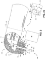
- the sleeve 38 and tip 40 are described below with reference to FIGS. 2 , 5 and 6 .
- U.S. Patent No. 6,389,193 describes an embodiment of a rotating handpiece that may be incorporated into the present invention to the extent compatible or modifiable by one skilled in the art to be compatible and not mutually exclusive. Additionally, other embodiments may be modified by one skilled in the art to be compatible and then incorporated into the present invention.
- Illumination device 10 having a plurality of proximal members 22A, 22B, and 22C.
- Proximal members 22A, 22B, and 22C have hollow interiors configured to accommodate one or more light transmitters or other tubular or elongate structures having cross-sectional areas less than the cross-sectional areas of the respective hollow interiors.
- Proximal members 22A, 22B, and 22C are arranged such that the hollow interiors of each of the proximal members is in communication with the lumen 14 ( FIG. 3 ) of elongate body 12. This arrangement provides for a substantially continuous path for the light transmitters to extend from proximal end P to distal end D of elongate body 12.
- the illustrated embodiment is provided with three proximal members, additional embodiments could be provided with two, or four or more proximal members, depending on, for example, a number of light transmitters being used in the illumination device 10.
- the illustrated embodiment of illumination device 10 includes two proximal members 22A and 22B that have substantially equal diameters, and one proximal member 22C that has a diameter that is less than either of the diameters of the other two proximal members.
- Illumination device 10 is illustrated as being configured to be held by a user.
- illumination device 10 is configured to direct electromagnetic energy from or in conjunction with the output portion 29 of handpiece 100 and/or to receive energy that may be generated (e.g., reflected from a target) in proximity to the handpiece 100.
- the illumination device 10 can be used in medical, industrial, dental, and other applications.
- the illumination device 10 is a device for emitting electromagnetic energy in dental applications.
- the electromagnetic energy preferably includes light, such as visible light, laser light (e.g., infrared laser light) and the like.
- the device can be used, for example, in dental hygiene procedures.
- Illumination device 10 is typically connected to at least one external electromagnetic energy source, such as a laser and/or one or more light emitting diodes (LEDs), and/or (in alternative embodiments) a lamp, so that electromagnetic energy generated by the electromagnetic energy source can be transmitted through illumination device 10 to the handpiece 100 and directed from the handpiece 100 to a target (e.g., a treatment surface such as a tooth).
- the electromagnetic energy source and/or other components may comprise parts or substantially all of that described in U.S. Patent No. 5,741,247 to the extent compatible or modifiable by one skilled in the art to be compatible and not mutually exclusive.
- fluid outputs and fluids e.g., fluid outputs and fluids as described in U.S. Patent No. 5,741,247
- the fluid outputs and fluids may comprise parts or substantially all of any of that described in U.S. Application No. 11/042,824, filed January 24, 2005 and entitled ELECTROMAGNETICALLY INDUCED TREATMENT DEVICES AND METHODS,.
- Distal portion 24 of the illumination device 10 of FIG. 1 can comprise, as presently embodied, a unitary structure having an inner lumen 14 ( FIG. 3 ) forming a distal portion tube.
- Proximal members 22A, 22B, and 22C of the proximal portion 26 can each have, in an exemplary embodiment, a lumen in communication with the lumen 14 of distal portion 24.
- proximal members 22A, 22B, and 22C can be integrally formed with distal portion 24 of the elongate body 12.
- one or more proximal members may comprise separate elements that are joined or connected to elongate body 12 so that the proximal member lumens are in communication with the hollow interior or lumen 14 of distal portion 24.
- distal end D includes an electromagnetic energy emitting internal output end 19 that, as presently embodied, coincides with phantom line E-E', and proximal end P includes an electromagnetic energy input end 27 ( FIG. 1 ).
- each proximal member can include a lumen dimensioned to accommodate one or more light transmitters or other tube- or fiber-like structures.
- proximal members 22A and 22B each contain three energy-emitting fibers, such as optical fibers, and proximal member 22C can contain six energy-emitting fibers, such as optical fibers.
- proximal member 22C being illustrated as having a smaller cross-sectional area relative to proximal members 22A and 22B, the cross-sectional area of each of the optical fibers (e.g., one, three, or six fibers) in proximal member 22C can be less than cross-sectional areas of the optical fibers in proximal members 22A and 22B.
- the proximal member 22A can comprise three optical fibers 16 that can be substantially fused together to define a unitary light emitting assembly or waveguide.
- the three optical fibers 16 may be joined by other means or not joined.
- proximal member 22B which may be similarly formed of fibers designated by reference numeral 17 in FIG. 3 , which is a cross-sectional view taken along line 3-3' of FIG. 2 near distal end D of elongate body 12.
- Proximal member 22C can include six relatively small fibers 18, as likewise is shown in the cross-sectional view of FIG. 3 .
- Fibers 18 are illustrated as being separate from each other, but in additional embodiments, two or more of the fibers 18 can be fused or otherwise joined together at or near one or more of the proximal end P and the distal end D.
- Fibers 16, 17 and 18 can be manufactured from plastic using conventional techniques, such as extrusion and the like.
- FIG. 1 Another optical fiber 20 is illustrated in FIG. 1 , passing between proximal members 22A and 22B near the input end 27 of elongate body 12, and being centrally disposed relative to fibers 16, 17 and 18 near the internal output end 19 ( FIG. 2 ) of elongate body 12 as shown in FIG. 3 .
- Optical fiber 20 is illustrated as a power erbium fiber that is structured to fit inside elongate body 12, although optical fiber 20 may comprise other structures in modified embodiments.
- fibers 16, 17, 18 and 20 may terminate at the internal output end 19 ( FIG. 2 ) located inside the elongate body 12. At the internal output end 19 ( FIG.
- the fibers 16, 17, 18, and 20 can be arranged in a plane to form a planar surface.
- the fibers can be cut and polished in the same plane and arranged to be maintained in a substantially fixed position relative to one another and the handpiece 100.
- tubing such as metal tubing, can be used both at the inside of elongate body 12 and outside of elongate body 12 to keep part, and preferably all, of the fibers 16, 17, 18 and 20 in a fixed, straight position.
- fibers 16 and 17 of respective proximal members 22A and 22B are configured to receive and transmit light from, for example, a laser and/or an LED, and/or, in alternative embodiments, a lamp.
- blue light 70 for example blue light generated by one or more blue light LEDs, is received by proximal members 22A and 22B.
- two blue light LEDs are used as a source of blue light for transmission through fibers 16 and 17, each LED generating, for example, electromagnetic energy at a wavelength of about 470 nanometers (nm) and a power level of about 200 milliwatts (mW) either in a continuous wave (CW) or pulsed mode.
- Blue light can be particularly useful in curing dental composites, whitening teeth, and detecting caries, among other things, when the illumination device 10 is used for dental care and hygiene.
- Each of the proximal members 22A and 22B is illustrated as including an optional light altering element such as, for example, a shutter mechanism or filter 42 to influence, for example, the transmission of blue light from the LEDs.
- each shutter mechanism or filter 42 is structured to convert blue light into white, or any other visible light. This conversion may be accomplished by using or placing phosphoric filters in front of each of the proximal members 22A and 22B.
- Proximal member 22C is configured to accommodate the six smaller optical fibers 18, as described above.
- optical fibers 18 are configured to collect or receive reflected and scattered light 64 ( FIG. 2 ) from a treatment output end 102 of handpiece 100 and to guide the reflected and scattered light 64 back toward the input end 27 ( FIG. 1 ).
- the reflected and/or scattered light can be used as a feedback signal 66, which can be passed to a sensor or other suitable device for analysis.
- the feedback signal 66 may be used, for example, by a microprocessor, to detect damage of an optical surface (e.g., a red light beam used for aiming may scatter and reflect back) or fluorescence of dental material (e.g., caries, bacteria, demineralization, and the like), among other things.
- an optical surface e.g., a red light beam used for aiming may scatter and reflect back
- dental material e.g., caries, bacteria, demineralization, and the like
- Use of the feedback signal 66 in detection of dental caries is described in co-pending U.S. Provisional Application No. 60/601,437, filed August 12, 2004 and entitled CARIES DETECTION USING TIMING DIFFERENTAILS BETWEEN EXCITATION AND RETURN PULSES.
- optical fiber 20 which may be an erbium fiber or other suitable laser emitting fiber, can be inserted into elongate body 12 such that a distal end of optical fiber 20 is coplanar (cf. plane coincident with phantom line E-E' of FIG. 2 ) with fibers 16, 17 and 18 at distal end D of illumination device 10.
- optical fiber 20 is centrally disposed along a central longitudinal axis of elongate body 12, as shown in FIGS. 2 and 3 .
- fibers 16, 17 and 18 are perimetrically disposed around optical fiber 20, at least at the distal end D of illumination device 10.
- the concentric configuration of fibers 16, 17, 18 and 20 can be maintained for any desired distance of elongate body 12. In the illustrated embodiment, the concentric configuration is maintained until a region, (e.g., proximal portion 26) where proximal members 22A, 22B, and 22C split from elongate body 12.
- light is emitted from and collected into the handpiece 100.
- light or other electromagnetic radiation is emitted from one or more of the fibers 16 and 17 at the internal output end 19 ( FIG. 2 ), and light is collected by fibers 18.
- light or other electromagnetic radiation from a laser, and/or an LED, and/or a lamp can be emitted from optical fiber 20.
- electromagnetic radiation 68 FIG.
- electromagnetic radiation 68 may further comprise an aiming beam, such as light having a wavelength of about 655 nm and an average power of about 1 mW emitted in a continuous-wave (CW) mode.
- CW continuous-wave
- blue and white light are emitted from one or more of the fibers 16 and 17 toward a working surface, reflected light from the working surface is collected by fibers 18, and erbium laser light is emitted from optical fiber 20.
- fibers 16, for example may emit blue light and fibers 17 may emit white light.
- appropriate light can be emitted by one or more of the fibers 16 and 17, causing reflected white light and/or stimulated fluorescent light to be collected by fibers 18.
- the emitted light may be directed toward a working surface, such as a tissue surface, including a surface of a tooth, to perform one or more light sensitive procedures.
- the present invention contemplates constructions and uses of visual feedback implements (e.g., cameras) as described in, for example, U.S. Provisional Application No. 60/688,109, filed June 6, 2005 and entitled ELECTROMAGNETIC RADIATION EMITTING TOOTHBRUSH AND DENTIFRICE SYSTEM (Att. Docket BI9887PR), and U.S. Provisional Application No. 60/687,991, filed June 6, 2005 and entitled METHODS FOR TREATING EYE CONDITIONS (Att.
- the senor may comprise one or more visual feedback implements.
- the visual feedback implement can be used, for example, (a) in a form that is integrated into a handpiece or output end of an electromagnetic energy output device, (b) in a form that is attached to the handpiece or electromagnetic energy output device, or (c) in conjunction with (e.g., not attached to) the handpiece or electromagnetic energy output device, wherein such handpieces and devices can facilitate cutting, ablating, treatments, and the like.
- Treatments can include low-level light treatments such as described in the above referenced U.S. Provisional Application No. 60/687,991 and U.S. Provisional Application No. 60/687,256, filed June 3, 2005 and entitled TISSUE TREATMENT DEVICE AND METHOD.
- one implementation may be useful for, among other things, optimizing, monitoring, or maximizing a cutting effect of an electromagnetic energy emitting device, such as a laser handpiece.
- the laser output can be directed, for example, into fluid (e.g., an air and/or water spray or an atomized distribution of fluid particles from a water connection and/or a spray connection near an output end of the handpiece) that is emitted from the handpiece above a target surface.
- fluid e.g., an air and/or water spray or an atomized distribution of fluid particles from a water connection and/or a spray connection near an output end of the handpiece
- An apparatus including corresponding structure for directing electromagnetic energy into an atomized distribution of fluid particles above a target surface is disclosed, for example, in the above-referenced U.S. Patent No. 5,574,247 .
- a visual feedback implement of (a) interactions between the electromagnetic energy and the fluid (e.g., above the target surface) and/or (b) cutting, ablating, treating or other impartations of disruptive surfaces to the target surface, can improve a quality of the procedure.
- visualization optical fibers e.g., a coherent fiber bundle
- the visual feedback implement can comprise an image-acquisition device (e.g., CCD or CMOS camera) for obtaining or processing images from the distal end D.
- the visual feedback implement can be built-in or attached (e.g., removably attached) to the handpiece and, further, can be disposed at various locations on or in connection with the handpiece between the proximal end P and distal end D, or proximally of the proximal end P.
- one or more of the optical fibers 16, 17, 18 and 20, and the visualization optical fibers can be arranged, for example, outside of the handpiece envelope.
- a few applications for the presently-described visual feedback implement may include periodontal pockets (e.g., diagnostic and treatment), endodontics (e.g., visualization of canals), micro-dentistry, tunnel preparations, caries detection and treatment, bacteria visualization and treatment, general dentistry, and airborne-agent and gas detection applications as described in the above-referenced U.S. Provisional Application No. 60/688,109 .
- electromagnetic radiation e.g., one or more of blue light, white light, infrared light, a laser beam, reflected/scattered light, fluorescent light, and the like, in any combination
- electromagnetic radiation may be transmitted in one or both directions through one or more of the fibers 16, 17, 18, and 20, in any combination.
- Outgoing and incoming beams of electromagnetic radiation can be separated or split, for example, according to one or more characteristics thereof, at the proximal end P ( FIG. 1 ) using a beam splitter, such as a wavelength-selective beam splitter (not shown), in a manner known to those skilled in the art.
- illumination device 10 may be useable in a person's hand or other suitable holding device to direct light toward a target surface.
- the illumination device 10 which may comprise an optical fiber 20 oriented in a direction nominally parallel to a longitudinal axis of the illumination device 10, may be separate from but configured to be coupled to a handpiece 100 as illustrated in FIG. 7 .
- Handpiece 100 FIG. 7
- Handpiece 100 which, in the illustrated embodiment, is structured to be held in a user's hand, can comprise a treatment output end 102 that is oriented at an angle relative to the longitudinal axis of the illumination device 10.
- Optical fiber 20 may terminate at an internal output end 11coinciding with phantom line F-F', of illumination device 10 in the embodiment shown in FIG. 7 .
- treatment output end 102 is oriented at an approximately ninety degree angle to the longitudinal axis of illumination device 10.
- a reflector 30 is provided with handpiece 100.
- An embodiment of reflector 30 can comprise a parabolic mirror as described in U.S. Patent No. 6,389,193 .
- reflector 30 may include a plurality of mirrors, such as first mirror 32 and second mirror 34.
- first and second mirrors 32 and 34 may comprise parabolic, toroidal, or flat surfaces. In additional embodiments, a fewer or greater number of mirrors may be provided.
- first mirror 32 is illustrated as being configured to alter light emitted from optical fiber 20.
- first mirror 32 is configured to direct, for example, a beam 28 generated by a laser source from the internal output end 19 to the treatment output end 102.
- Second mirror 34 is illustrated as being configured to alter a path of light emitted from one or more of the fibers 16 and 17.
- mirror 34 can be configured to direct one or more beams of light, such as blue light or white light, from the internal output end 19 to the treatment output end 102.
- mirror 34 can be configured to direct light 64, which is reflected back from the target surface, toward fibers 18 (not visible in FIG. 2 ) for the provision of, for example, a signal that can be used for analysis, as described above. Either or both of mirrors 32 and 34 may be removable and replaceable.
- handpiece 100 is also illustrated as including a tip 40 to direct electromagnetic energy (e.g., light), as indicated by reference number 62, that is emitted from optical fiber 20 toward a target surface.
- electromagnetic energy e.g., light
- a sleeve 38 may be provided with handpiece 100, wherein sleeve 38 may partially, substantially, or completely (e.g., wherein sleeve 38 comprises a ring or cylindrical shape) surround tip 40.
- sleeve 38 can be constructed of a material that is substantially transparent to permit light 60 emitted from fibers 16 and/or 17, such as white light, to be directed to a target surface.
- Light 60 may be used, for example, to illuminate the target surface.
- First and second mirrors 32 and 34 may also be constructed to focus one or more of the light beams into tip 40.
- the first mirror 32 is constructed to focus the erbium laser beam emitted from optical fiber 20 into tip 40
- the second mirror 34 is constructed to focus the light emitted from fibers 16 and 17, such as blue light, white light, or other light, into sleeve 38.
- An embodiment of the handpiece 100 may comprise a plurality of LEDs (e.g., 2 or more, such as about 6 to 12, and in one implementation 10) concentrically disposed around the tip 40 in order to provide, according to certain implementations, one or more of a relatively bright, ultra-white and shadow-free illumination system that may significantly enhance maneuverability relative to, access to, and visibility of, a working surface.
- a relatively bright, ultra-white and shadow-free illumination system may significantly enhance maneuverability relative to, access to, and visibility of, a working surface.
- any one or more of the above characteristics, such as enhanced illumination may provide for significantly improved efficacy, accuracy and patient comfort.
- the tip 40 further may be surrounded by a tip ferrule 50.
- FIG. 5 is a magnified side elevation view showing a combination of the tip 40 and the tip ferrule 50.
- the tip ferrule 50 in the illustrated embodiment comprises a groove 52 that may be used to extract the tip ferrule 50 and, consequently, the tip 40 from the handpiece 100.
- the tip ferrule 50 in the illustrated embodiment further comprises a plurality of ring-shaped projections 53 (see also FIG. 2 ) that make contact with an interior of the sleeve 38 of the handpiece 100.
- Another embodiment of the tip ferrule 50 replaces the plurality of ring-shaped projections 53 with a plurality of O-rings.
- the tip ferrule 50 may have at least one locking shoulder 54 and, in certain embodiments, may have a plurality of locking shoulders.
- the locking shoulder is capable of providing a "click" or “snap" feedback when the tip ferrule 50 is fitted into a recess 58 ( FIG. 2 ), which recess is formed by structure of one or more of the treatment end 102, the handpiece 100 and the sleeve 38.
- a locking shoulder can be formed, instead, by structure of one or more of the treatment end, the handpiece and the sleeve; and a recess can be formed, instead, in the tip ferrule, so that the locking shoulder is capable of providing a "click" or "snap” feedback when the tip ferrule is fitted into the recess.
- the click or snap feedback can facilitate the securing or locking of the tip ferrule 50 to the handpiece 100.
- audible and/or tactile feedback in the form of a "click” or, in modified embodiments, other forms, can be provided to a user when an optical waveguide (e.g., tip 40), which is secured to the tip ferrule 50, is properly installed.
- the tip 40 can be secured to the tip ferrule 40 by way of inserting an adhesive into a cavity 51 or gap disposed at a distal end of the tip ferrule 50, which cavity 51 is depicted in FIG. 2 as a distal portion of the tip ferrule 50 that surrounds but does not contact the tip 40.
- FIG. 6 is an on-axis top view of the tip ferrule 50 and tip 40 of FIG. 5 .
- the tip ferrule 50 comprises four locking shoulders capable of providing a "click” or “snap” feedback when the tip ferrule 50 is fitted into the recess 58 ( FIG. 2 ).
- one or more gaps 56 disposed between locking shoulders may provide for a spring action capable, at least in part, of producing the click or snap feedback referred to above.
- a facility may be provided for mixing spray air and spray water that may be directed toward a target surface.
- An illustration of an embodiment of a chamber for mixing spray air and spray water in the distal portion 24 of handpiece 100 is shown in FIG. 2a .
- a mixing chamber 80 (see also FIG. 2 ) comprises an air intake 83, which is connected to, for example, tubing (not shown) in the elongate body 12 that supplies spray air.
- a water intake 84 receives fluid (e.g., water) from, for example, tubing (not shown) in the elongate body 12 that supplies water.
- the air intake 83 and the water intake 84 which may have circular cross-sections about 250 ⁇ m in diameter, join at an angle 82 that may approximate 110° in a typical embodiment.
- mixing may occur or begin to occur in a neighborhood where the air intake 83 and water intake 84 join, and a spray mixture 86 of water and air (e.g., particles or atomized particles) may be ejected through a fluid output 85.
- Fluid output 85 may have a circular cross-section measuring about 350 ⁇ m in diameter.
- a typical embodiment can comprise, for example, three such fluid outputs surrounding the tip 40 and tip ferrule 50 illustrated in FIG. 2 .
- fluid outputs may, for example, correspond to, comprise parts of, or comprise substantially all of, any of fluid outputs described in U.S. Application No. 11/042,824, filed January 24, 2005 and entitled ELECTROMAGNETICALLY INDUCED TREATMENT DEVICES AND METHODS.
- Handpiece 100 may further include another tip structure 36, such as a curing tip, as illustrated in FIG. 2 .
- Tip structure 36 can be coupled with tip 40 or, as presently embodied, can replace tip 40.
- the tip structure 36 may comprise a hollow center for accommodating the tip 40 therethrough.
- tip structure 36 can be coupled with or can replace both tip 40 and sleeve 38.
- the tip structure 36 may abut against an output end of sleeve 38 and further may comprise a hollow center for accommodating the tip 40.
- tip structure 36 in the illustrated embodiment comprises a cylindrical shape (e.g., a solid cylinder) that surrounds a space of tip 40, which space may or may not be occupied
- other embodiments may comprise a tip structure that only partially surrounds the space (occupied or not) of tip 40.
- the curing tip can be positioned in handpiece 100 and configured to receive or collect light (e.g., blue light) emitted from, for example, fibers 16 to direct the light toward a target surface and obtain a desired effect, such as curing of dental composites.
- a diameter can be chosen for tip structure 36 that will optimize or maximize a characteristic (e.g., an amount) of light collected.
- Tip 40 and tip structure 36 can be formed of a plastic-like material, including a plurality of plastic materials, that is/are optically transparent to permit the light to be effectively transmitted therethrough to and from a target surface.
- illumination device 10 may have a total length of between about 1 and about 2 meters. In one particular embodiment, illumination device 10 can be about 1.6 meters long.
- Each proximal member 22A and 22B may have a diameter between about 2 millimeters (mm) and about 5 mm, such as about 3 mm.
- proximal members 22A, 22B, and 22C meet to define a unitary tubular structure having an outer diameter between about 4 mm and about 5 mm, such as about 4.5 mm (or about 3/16 of an inch).
- Proximal members 22A, 22B, and 22C may be arranged so that the fibers contained therein define a central lumen having a diameter ranging from about 1 mm to about 2 mm, such as about 1.5 mm (or about 1/16 of an inch).
- This central lumen can be structured to accommodate a power erbium laser fiber, such as optical fiber 20 capable of transmitting, for example, concentrated infrared electromagnetic energy.
- proximal members 22A, 22B, and 22C are routed together to form a unitary structure at a distance of approximately 5 centimeters (cm) from the proximal end P of elongate body 12.
- Power erbium optical fiber 20 may have a diameter of approximately 0.8 mm, and fibers 16 and, optionally, fibers 17, may have a diameter of about 1.5 mm. Fibers 18 may be about 0.5 mm in diameter.
- the internal output end 19 of illumination device 10 can include a substantially rigid, straight portion that is approximately 10 centimeters in length. Illumination device 10 can include six larger-diameter fibers, such as six fibers 16, or optionally can include three larger-diameter fibers 16 and three larger-diameter fibers 17 as shown in FIG. 3 concentrically arranged about a central lumen with six relatively smaller diameter fibers 18 concentrically arranged about the same central lumen.
- the numerical apertures of fibers 16 (and, optionally, fibers 17) and 18 can be about 0.68.
- Light provided by two high power blue LEDs which light may comprise visible electromagnetic energy relatively less concentrated than the infrared energy referred to above, may be directed into proximal members 22A and 22B to cure dental composites, whiten teeth, and/or detect dental caries.
- Each blue light LED can have a power of approximately 1 ⁇ 2 W.
- a high-power blue LED is a Luxeon Emitter, 5 W Dental, which emits light having a wavelength in a range of about 450 nm to about 470 nm with a bandwidth of about 20 nm (Model No. LXHL-PRD5).
- two phosphoric filters can be placed in a light path between the blue light emitting LEDs and proximal members 22A and 22B.
- the phosphoric filters may be used as white-light shutters to provide white light to the target surface, as discussed above.
- the white light that is generated from filtering the blue light is typically reduced in power relative to the blue light. In the embodiment illustrated in FIG. 1 , the white light is reduced to a range of about twenty percent to about thirty percent of the power of the blue light. Additional filters can be provided to alter the white light, as may be desired.
- a blue light filter is placed at the proximal end of each of the proximal members 22A and 22B. In other embodiments, however, the filters can be located at any location along the illumination device 10, including at the distal end.
- an illumination device that utilizes electromagnetic energy to affect a target surface.
- the illumination device includes an optical fiber for transmitting laser energy to a target surface for treating (e.g., ablating) a dental structure, such as a tooth, a plurality of optical fibers for transmitting blue light for illumination, curing, whitening, and/or diagnostics of a tooth, a plurality of optical fibers for transmitting for example white light to a tooth to provide illumination of the target surface, and a plurality of optical fibers for transmitting light from the target surface back to a sensor for analysis.
- the optical fibers that transmit blue light also transmit white light.
- an illumination device comprises an illumination tube having a feedback signal end and a double mirror handpiece.
- the methods and apparatuses of the above embodiments can be configured and implemented for use, to the extent compatible and/or not mutually exclusive, with existing technologies including any of the above-referenced apparatuses and methods.
- the laser output (e.g., from a power fiber) can be directed, for example, into fluid (e.g., an air and/or water spray or an atomized distribution of fluid particles from a water connection and/or a spray connection near the treatment output end 102) that is emitted from a fluid output of the handpiece 100 at the treatment output end 102 above a target surface (e.g., one or more of tooth, bone, cartilage and soft tissue).
- the fluid output may comprise a plurality of fluid outputs, concentrically arranged around a power fiber, as described in, for example, U.S. Application No.
- the power fiber may comprise, for example, optical fiber 20, and in various implementations may be coupled to an electromagnetic energy source comprising one or more of a wavelength within a range from about 2.69 to about 2.80 microns and a wavelength of about 2.94 microns.
- the power fiber may be coupled to one or more of an Er:YAG laser, an Er:YSGG laser, an Er, Cr:YSGG laser and a CTE:YAG laser, and in particular instances may be coupled to one of an Er, Cr:YSGG solid state laser having a wavelength of about 2.789 microns and an Er:YAG solid state laser having a wavelength of about 2.940 microns.
- An apparatus including corresponding structure for directing electromagnetic energy into an atomized distribution of fluid particles above a target surface is disclosed in the above-referenced U.S. Patent No. 5,574,247 .
- Large amounts of laser energy can be imparted into the fluid (e.g., atomized fluid particles), which can comprise water, to thereby expand the fluid (e.g., fluid particles) and apply disruptive (e.g., mechanical) cutting forces to the target surface.
- the optical fibers and/or tip ferrules referred to herein may comprise plastic and/or be color coded to designate predetermined or predefined sizes, shapes or other properties. These materials may all be autoclavable.
- the tip ferrule and corresponding structure may comprise parts or substantially all of any of that described in U.S. Patent No. 6,567,582 , entitled FIBER TIP FLUID OUTPUT DEVICE, and in co-pending application entitled OUTPUT ATTACHMENTS CODED FOR USE WITH ELECTROMAGNETIC-ENERGY PROCEDURAL DEVICE to the extent compatible; or, in other embodiments, structures described in the referenced patents may be modified to be compatible with the device tip ferrule 50 disclosed in FIGS. 5 and 6 .
Landscapes
- Physics & Mathematics (AREA)
- Electromagnetism (AREA)
- Engineering & Computer Science (AREA)
- Optics & Photonics (AREA)
- Health & Medical Sciences (AREA)
- Plasma & Fusion (AREA)
- Surgery (AREA)
- Life Sciences & Earth Sciences (AREA)
- Heart & Thoracic Surgery (AREA)
- Public Health (AREA)
- Otolaryngology (AREA)
- Medical Informatics (AREA)
- Molecular Biology (AREA)
- Animal Behavior & Ethology (AREA)
- General Health & Medical Sciences (AREA)
- Biomedical Technology (AREA)
- Veterinary Medicine (AREA)
- Microelectronics & Electronic Packaging (AREA)
- Nuclear Medicine, Radiotherapy & Molecular Imaging (AREA)
- Laser Surgery Devices (AREA)
- Radiation-Therapy Devices (AREA)
- Dental Tools And Instruments Or Auxiliary Dental Instruments (AREA)
Claims (14)
- Système d'éclairage destiné à diriger de l'énergie électromagnétique jusqu'à une cible, comprenant :un dispositif d'éclairage (10) comprenant une extrémité proximale (P), une extrémité distale (D) et un axe longitudinal, le dispositif d'éclairage (10) comportant :une fibre d'alimentation (20) s'étendant de l'extrémité proximale (P) à l'extrémité distale (D) ;une pluralité de premières fibres optiques (16 ; 17) disposées de façon concentrique autour de la fibre d'alimentation (20) et s'étendant de l'extrémité proximale (P) à l'extrémité distale (D), la pluralité de premières fibres optiques (16 ; 17) étant configurée pour recevoir un premier type d'énergie électromagnétique depuis l'extrémité proximale (P) et pour délivrer le premier type d'énergie électromagnétique à l'extrémité distale (D) ; etune pluralité de deuxièmes fibres optiques (18) disposées de façon concentrique autour de la fibre d'alimentation (20) et s'étendant de l'extrémité proximale (P) à l'extrémité distale (D), la pluralité de deuxièmes fibres optiques (20) étant configurée pour recevoir un deuxième type d'énergie électromagnétique depuis l'extrémité distale (D) et pour diriger le deuxième type d'énergie électromagnétique jusqu'à l'extrémité proximale (P) ;une pièce à main (100) comprenant une extrémité de sortie de traitement (102) destinée à émettre un rayonnement électromagnétique depuis et collecter un rayonnement électromagnétique à l'intérieur de la pièce à main (100), la pièce à main (100) étant structurée pour être tenue dans la main d'un utilisateur et étant couplée à l'extrémité distale (D) du dispositif d'éclairage (10), l'extrémité de sortie de traitement (102) étant orientée à un angle par rapport à l'axe longitudinal du dispositif d'éclairage (10) ; etune sortie de fluide (85), la sortie de fluide (85) comprenant un atomiseur configuré pour placer des particules de fluide atomisées à l'intérieur d'un volume au-dessus d'une surface cible ;dans lequel la fibre d'alimentation (20) est configurée pour apporter des quantités d'énergie relativement importantes à l'intérieur des particules de fluide atomisées dans le volume au-dessus de la surface cible pour détendre ainsi les particules de fluide atomisées et appliquer des forces disruptives sur la surface cible ;dans lequel la pièce à main (100) est configurée pour tourner par rapport à l'extrémité distale (D) du dispositif d'éclairage (10) autour de l'axe longitudinal du dispositif d'éclairage, la pièce à main comprenant au moins un réflecteur (30 ; 32, 34) destiné à, indépendamment d'un angle de rotation de la pièce à main (100) par rapport à l'extrémité distale (D) du dispositif d'éclairage (10), diriger de l'énergie électromagnétique de la fibre d'alimentation (20) et de la pluralité de premières fibres optiques (16 ; 17) depuis l'extrémité distale (D) du dispositif d'éclairage (10) jusqu'à l'extrémité de sortie de traitement (102) de la pièce à main (10) et à diriger de l'énergie électromagnétique, qui est rétroréfléchie depuis la surface cible, depuis l'extrémité de sortie de traitement (102) de la pièce à main (100) vers la pluralité de deuxièmes fibres optiques (18) à l'extrémité distale (D) du dispositif d'éclairage (10).
- Système d'éclairage selon la revendication 1, dans lequel le réflecteur (30) comprend :un premier miroir (32) destiné à diriger de l'énergie électromagnétique de la fibre d'alimentation (20) depuis l'extrémité distale (D) du dispositif d'éclairage (10) jusqu'à l'extrémité de sortie de traitement (102) de la pièce à main (10) ; etun deuxième miroir (34) destiné à diriger de l'énergie électromagnétique de la pluralité de premières fibres optiques (16 ; 17) depuis l'extrémité distale (D) du dispositif d'éclairage (10) jusqu'à l'extrémité de sortie de traitement (102) de la pièce à main (10) et à diriger de l'énergie électromagnétique, qui est rétroréfléchie depuis la surface cible, depuis l'extrémité de sortie de traitement (102) de la pièce à main (100) vers la pluralité de deuxièmes fibres optiques (18) à l'extrémité distale (D) du dispositif d'éclairage (10).
- Système d'éclairage selon la revendication 2, comprenant en outre :une pointe (40) destinée à diriger de l'énergie électromagnétique vers la surface cible ; etun manchon (38) entourant la pointe (40) ;dans lequel le premier miroir (32) est construit pour focaliser l'énergie électromagnétique émise depuis la fibre d'alimentation (20) à l'intérieur de la pointe (40), le deuxième miroir (34) est construit pour focaliser l'énergie électromagnétique émise depuis la pluralité de premières fibres optiques (16 ; 17) à l'intérieur du manchon (38), et le manchon (38) est construit dans un matériau qui est sensiblement transparent pour pouvoir diriger l'énergie électromagnétique émise depuis la pluralité de premières fibres optiques (16 ; 17) jusqu'à la surface cible.
- Système d'éclairage selon la revendication 1, le dispositif d'éclairage (10) comprenant en outre :une pluralité de troisièmes fibres optiques (16 ; 17) s'étendant de l'extrémité proximale (P) à l'extrémité distale (D), la pluralité de troisièmes fibres optiques pouvant recevoir un troisième type d'énergie électromagnétique depuis l'extrémité distale (D) et diriger le troisième type d'énergie électromagnétique jusqu'à l'extrémité proximale (P) ; etune caméra couplée pour recevoir le troisième type d'énergie électromagnétique depuis au moins une partie de la pluralité de troisièmes fibres optiques.
- Système d'éclairage selon la revendication 1, la pièce à main (100) comprenant en outre :une ferrule de pointe (50) insérable dans l'extrémité de traitement (102), la ferrule de pointe comprenant une extrémité distale ; etune pointe de fibre (40) insérable dans la ferrule de pointe (50), la pointe de fibre (40) pouvant recevoir de l'énergie électromagnétique depuis l'extrémité distale du dispositif d'éclairage (10).
- Système d'éclairage selon la revendication 5, dans lequel la pointe de fibre (40) est fixée à l'intérieur de la ferrule de pointe (50) par le fonctionnement d'une cavité formée dans l'extrémité distale de la ferrule de pointe (50), la cavité entourant, mais ne touchant pas la pointe de fibre (40).
- Système d'éclairage selon la revendication 1, le dispositif d'éclairage (10) comprenant en outre un corps allongé (12) avec une partie rigide et au moins une partie sensiblement souple, l'au moins une partie sensiblement souple comprenant une section articulée.
- Système d'éclairage selon la revendication 7, dans lequel la section articulée prend dans une position neutre un angle d'environ 15 à 20 degrés par rapport à un axe de la partie rigide du corps allongé (12).
- Système d'éclairage selon la revendication 1, la pièce à main (100) comprenant en outre une ferrule de pointe (50) avec une pointe de fibre (40) fixée à l'intérieur de la ferrule de pointe (50) par le fonctionnement d'une cavité formée dans une extrémité distale de la ferrule de pointe (50), la cavité entourant, mais ne touchant pas, la pointe de fibre.
- Système d'éclairage selon la revendication 3 ou 9, dans lequel la ferrule de pointe (50) comprend :une rainure (52) entourant au moins partiellement l'extrémité distale de la ferrule de pointe (50), la rainure pouvant faciliter le retrait de la ferrule de pointe (50) de l'extrémité de traitement (102) ; etune pluralité de saillies de forme annulaire (53), une ou plusieurs des saillies de forme annulaire pouvant établir un contact avec un intérieur de l'extrémité de traitement quand la ferrule de pointe est insérée dans l'extrémité de traitement.
- Système d'éclairage selon l'une quelconque des revendications précédentes, dans lequel la fibre d'alimentation (20) peut être couplée à au moins un laser parmi un laser Er:YAG, un laser Er:YSGG, un laser Er,Cr:YSGG et un laser CTE:YAG.
- Système d'éclairage selon la revendication 1, le dispositif d'éclairage (10) comprenant en outre un capteur de lumière couplé pour recevoir de la lumière depuis la pluralité de deuxièmes fibres optiques à l'extrémité proximale (P).
- Système d'éclairage selon la revendication 1, la pièce à main (100) comportant en outre :une extrémité de traitement ayant un manchon (38) disposé à l'intérieur, le manchon (38) comprenant une encoche (58) disposée sur une surface interne de celui-ci ;une ferrule de pointe (50) disposée au moins en partie à l'intérieur du manchon (38), la ferrule de pointe (50) comprenant un épaulement de verrouillage (54) pouvant entrer en prise avec l'encoche (58) ; etune pointe de fibre (40), dont au moins une partie est disposée à l'intérieur de la ferrule de pointe (50).
- Système d'éclairage selon la revendication 1, la pièce à main comportant en outre :une extrémité de traitement construite pour faciliter l'émission d'énergie électromagnétique ;une ferrule de pointe (50) insérable dans l'extrémité de traitement, la ferrule de pointe (50) comprenant une extrémité distale ; etune pointe de fibre (40) insérable dans la ferrule de pointe (50), la pointe de fibre (40) pouvant recevoir et délivrer de l'énergie électromagnétique depuis l'extrémité de traitement ;dans lequel l'insertion de la ferrule de pointe (50) dans l'extrémité de traitement fournit un retour sonore et/ou un retour tactile.
Applications Claiming Priority (2)
| Application Number | Priority Date | Filing Date | Title |
|---|---|---|---|
| US59193304P | 2004-07-27 | 2004-07-27 | |
| PCT/US2005/025957 WO2006012461A2 (fr) | 2004-07-27 | 2005-07-20 | Piece a main a contre-angle rotative presentant une virole a pointe a retroaction tactile |
Publications (3)
| Publication Number | Publication Date |
|---|---|
| EP1799404A2 EP1799404A2 (fr) | 2007-06-27 |
| EP1799404A4 EP1799404A4 (fr) | 2010-07-14 |
| EP1799404B1 true EP1799404B1 (fr) | 2020-01-08 |
Family
ID=35787833
Family Applications (1)
| Application Number | Title | Priority Date | Filing Date |
|---|---|---|---|
| EP05775222.2A Active EP1799404B1 (fr) | 2004-07-27 | 2005-07-20 | Piece a main a contre-angle rotative presentant une virole a pointe a retroaction tactile |
Country Status (7)
| Country | Link |
|---|---|
| US (2) | US7630420B2 (fr) |
| EP (1) | EP1799404B1 (fr) |
| JP (1) | JP2008508034A (fr) |
| CN (1) | CN101432102A (fr) |
| AU (1) | AU2005267072B2 (fr) |
| CA (1) | CA2575443C (fr) |
| WO (2) | WO2006012461A2 (fr) |
Families Citing this family (29)
| Publication number | Priority date | Publication date | Assignee | Title |
|---|---|---|---|---|
| SI2329785T1 (sl) * | 2004-01-22 | 2013-07-31 | Biolase, Inc. | Elektromagneto inducirane obdelovalne naprave |
| WO2006036337A2 (fr) * | 2004-08-13 | 2006-04-06 | Biolase Technology, Inc. | Architecture de piece a main laser et procedes associes |
| JP5183200B2 (ja) * | 2004-08-13 | 2013-04-17 | バイオレーズ テクノロジー インコーポレイテッド | プリセットを有するデュアル・パルス幅医療用レーザ |
| KR20110074936A (ko) * | 2005-06-24 | 2011-07-04 | 바이오레이즈 테크놀로지, 인크. | 전자기 에너지 출력 장치 |
| EP3311770B1 (fr) | 2006-04-20 | 2023-06-21 | Sonendo, Inc. | Appareil de traitement des canaux radiculaires des dents |
| US10835355B2 (en) | 2006-04-20 | 2020-11-17 | Sonendo, Inc. | Apparatus and methods for treating root canals of teeth |
| US7980854B2 (en) | 2006-08-24 | 2011-07-19 | Medical Dental Advanced Technologies Group, L.L.C. | Dental and medical treatments and procedures |
| JP2009028278A (ja) * | 2007-07-26 | 2009-02-12 | Panasonic Electric Works Co Ltd | 光照射美容器具 |
| WO2010045461A1 (fr) | 2008-10-15 | 2010-04-22 | Biolase Technology, Inc. | Dispositif de traitement à énergie électromagnétique avec plateforme à fonctions multiples |
| WO2010062969A1 (fr) | 2008-11-29 | 2010-06-03 | Biolase Technology, Inc. | Pièce à main sans contact pour la découpe laser de tissus |
| CA2780800C (fr) | 2009-11-13 | 2023-09-12 | Sonendo, Inc. | Appareil a jet de liquide et procedes pour des traitements dentaires |
| CN107115154B (zh) | 2010-10-21 | 2021-06-15 | 索南多股份有限公司 | 用于牙髓治疗的设备、方法和组合 |
| WO2012061208A1 (fr) | 2010-11-04 | 2012-05-10 | Biolase Technology, Inc. | Séquences de déclenchement pour accélérer la puissance d'impulsion dans laser médical ayant des sous-impulsions avant de grande intensité |
| EP2548530B1 (fr) | 2011-07-19 | 2014-03-19 | W & H Dentalwerk Bürmoos GmbH | Dispositif d'éclairage pour instrument médical, notamment dentaire |
| AU2013235347B2 (en) | 2012-03-22 | 2017-11-09 | Sonendo, Inc. | Apparatus and methods for cleaning teeth |
| US10631962B2 (en) | 2012-04-13 | 2020-04-28 | Sonendo, Inc. | Apparatus and methods for cleaning teeth and gingival pockets |
| EP3572036B1 (fr) | 2012-12-20 | 2021-05-26 | Sonendo, Inc. | Appareil de nettoyage de dents et de canaux radiculaires |
| US10363120B2 (en) | 2012-12-20 | 2019-07-30 | Sonendo, Inc. | Apparatus and methods for cleaning teeth and root canals |
| EP4218658A3 (fr) | 2013-05-01 | 2023-08-09 | Sonendo, Inc. | Apparatus and system for treating teeth |
| US9877801B2 (en) | 2013-06-26 | 2018-01-30 | Sonendo, Inc. | Apparatus and methods for filling teeth and root canals |
| US9306386B2 (en) * | 2013-09-13 | 2016-04-05 | Raytheon Company | Electromagnetic DC pulse power system including integrated fault limiter |
| CA2945691C (fr) | 2014-01-31 | 2023-07-25 | Biolase, Inc. | Dispositif de traitement laser a multiples faisceaux |
| US11154359B2 (en) * | 2015-09-07 | 2021-10-26 | Advanced Osteotomy Tools—AOT AG | Bone cut treatment |
| US10806544B2 (en) | 2016-04-04 | 2020-10-20 | Sonendo, Inc. | Systems and methods for removing foreign objects from root canals |
| KR102013791B1 (ko) * | 2018-05-17 | 2019-08-23 | 허진 | 레이저 조사 장치 |
| WO2020142518A1 (fr) * | 2019-01-02 | 2020-07-09 | Acera LLC | Positionnement d'un tube dans une lumière par transillumination |
| US11389241B2 (en) | 2019-01-15 | 2022-07-19 | Boston Scientific Scimed, Inc. | Alignment method and tools |
| CN110859668B (zh) * | 2019-11-15 | 2021-05-25 | 武汉芸禾光电技术有限公司 | 一种组合脉冲大功率半导体激光治疗仪驱动装置及系统 |
| USD997355S1 (en) | 2020-10-07 | 2023-08-29 | Sonendo, Inc. | Dental treatment instrument |
Citations (2)
| Publication number | Priority date | Publication date | Assignee | Title |
|---|---|---|---|---|
| US6118521A (en) * | 1996-01-02 | 2000-09-12 | Lj Laboratories, L.L.C. | Apparatus and method for measuring optical characteristics of an object |
| US6389193B1 (en) * | 1998-12-22 | 2002-05-14 | Biolase Technology, Inc. | Rotating handpiece |
Family Cites Families (109)
| Publication number | Priority date | Publication date | Assignee | Title |
|---|---|---|---|---|
| US569046A (en) * | 1896-10-06 | Anton larsen | ||
| US3051906A (en) * | 1958-05-26 | 1962-08-28 | Itt | Pulse waveform synthesizer using plurality of individually charged storage means sequentially discharged through common load |
| US5552675A (en) * | 1959-04-08 | 1996-09-03 | Lemelson; Jerome H. | High temperature reaction apparatus |
| GB1242123A (en) * | 1968-11-12 | 1971-08-11 | Nat Res Dev | Improvements relating to a method and apparatus for laser beam cutting |
| US3679998A (en) * | 1971-01-21 | 1972-07-25 | Hughes Aircraft Co | Laser flashtube triggering arrangement |
| US3914648A (en) * | 1974-05-10 | 1975-10-21 | Avco Everett Res Lab Inc | Flashlamp discharge circuit |
| US4005333A (en) * | 1974-06-03 | 1977-01-25 | Hughes Aircraft Company | Apparatus for increasing output efficiency of an optically pumped Nd:YAG laser |
| JPS5157283A (en) * | 1974-11-15 | 1976-05-19 | Nippon Electric Co | Handotaikibanno bunkatsuhoho |
| US4092864A (en) | 1976-08-04 | 1978-06-06 | Qualitrol Corporation | Hot spot thermometer |
| US4087705A (en) * | 1977-02-10 | 1978-05-02 | Ritter Corporation | High power variable pulse width triggering circuits |
| GB2023330B (en) | 1978-04-28 | 1982-05-06 | Lasers Ltd J K | Laser flashtube power supply |
| US4276518A (en) * | 1978-05-01 | 1981-06-30 | The United States Of America As Represented By The Secretary Of The Navy | Optical oscillator |
| NL7902158A (nl) * | 1979-03-20 | 1980-09-23 | Philips Nv | Handhaardroger. |
| JPS5945092A (ja) | 1982-09-06 | 1984-03-13 | Fuji Denpa Koki Kk | レ−ザ加工装置 |
| US4550275A (en) * | 1983-10-07 | 1985-10-29 | The United States Of America As Represented By The Secretary Of The Air Force | High efficiency pulse ultraviolet light source |
| US4862888A (en) * | 1983-10-28 | 1989-09-05 | Bausch & Lomb Incorporated | Laser system |
| GB8428411D0 (en) | 1984-11-09 | 1984-12-19 | Micra Ltd | Laser knives |
| DE3506249A1 (de) | 1985-02-22 | 1986-08-28 | Messerschmitt-Bölkow-Blohm GmbH, 8012 Ottobrunn | Verfahren und vorrichtung zur zertruemmerung eines festen koerpers |
| US4913142A (en) * | 1985-03-22 | 1990-04-03 | Massachusetts Institute Of Technology | Catheter for laser angiosurgery |
| US4770811A (en) * | 1985-03-22 | 1988-09-13 | Kigre, Inc. | Sensitized laser glass |
| US5318024A (en) * | 1985-03-22 | 1994-06-07 | Massachusetts Institute Of Technology | Laser endoscope for spectroscopic imaging |
| US4910438A (en) * | 1985-12-17 | 1990-03-20 | Hughes Aircraft Company | Wide band, high efficiency simmer power supply for a laser flashlamp |
| DE3719561C2 (de) * | 1986-06-12 | 1998-12-10 | Morita Mfg | Medizinisches Lichtbestrahlungshandstück |
| US4724299A (en) * | 1987-04-15 | 1988-02-09 | Quantum Laser Corporation | Laser spray nozzle and method |
| US4908030A (en) * | 1987-04-29 | 1990-03-13 | Vent-Plant Corporation, Inc. | Method of manufacturing synthetic bone coated surgical implants |
| US4931047A (en) | 1987-09-30 | 1990-06-05 | Cavitron, Inc. | Method and apparatus for providing enhanced tissue fragmentation and/or hemostasis |
| JPH03505683A (ja) | 1988-10-25 | 1991-12-12 | カール シュトルツ ゲーエムベーハー アンド カンパニー | 流体によって囲まれた固体を粉砕する方法及び装置 |
| DE3840126A1 (de) | 1988-11-29 | 1990-05-31 | Messerschmitt Boelkow Blohm | Schutzeinrichtung fuer einen fasergekoppelten laser-lithotripter |
| US5885082A (en) * | 1988-12-21 | 1999-03-23 | Endo Technic International Corporation | Dental and medical procedures employing laser radiation |
| US5151029A (en) * | 1988-12-21 | 1992-09-29 | Endo Technic Corporation | Removing physiologic tissue from a tooth canal |
| US5092773A (en) * | 1989-01-18 | 1992-03-03 | Endo Technic Corporation | Method and apparatus for filling a tooth canal |
| DE3911871A1 (de) * | 1989-04-11 | 1990-10-25 | Aesculap Ag | Verfahren zum zerstoeren und abtragen von zahnmaterial |
| US4985027A (en) * | 1990-02-26 | 1991-01-15 | Dressel Thomas D | Soft tissue aspiration device and method |
| US5102410A (en) * | 1990-02-26 | 1992-04-07 | Dressel Thomas D | Soft tissue cutting aspiration device and method |
| US5059200A (en) | 1990-04-06 | 1991-10-22 | John Tulip | Laser lithotripsy |
| US5092864A (en) * | 1990-04-30 | 1992-03-03 | Microfab Technologies, Inc. | Method and apparatus for improved laser surgery |
| SE469454B (sv) | 1990-07-11 | 1993-07-05 | Radi Medical Systems | Fiberoptisk anslutning och anvaendning daerav |
| US5086378A (en) * | 1990-08-20 | 1992-02-04 | Prince Mark W | Fiber optic finger light |
| US5756982A (en) * | 1990-09-11 | 1998-05-26 | Metrologic Instruments, Inc. | Body-wearable automatic laser scanner with power-conserving control subsystem |
| JPH05506601A (ja) * | 1991-02-19 | 1993-09-30 | アドバンスト インターベンショナル システムズ,インコーポレイテッド | 高エネルギーパルスレーザ光のガイド及び伝送システム |
| FR2674768B1 (fr) * | 1991-04-02 | 1994-09-02 | France Telecom | Procede de traitement photochimique d'un materiau utilisant une source de lumiere a tubes a eclairs. |
| US5263950A (en) * | 1991-07-24 | 1993-11-23 | L'esperance Medical Technologies, Inc. | Phaco-extractor for fragmenting cataractous-lens situs of fragmentation |
| US5267856A (en) * | 1991-09-20 | 1993-12-07 | Premier Laser Systems, Inc. | Laser surgical method |
| US5713845A (en) | 1991-10-29 | 1998-02-03 | Thermolase Corporation | Laser assisted drug delivery |
| DE4138468A1 (de) | 1991-11-22 | 1993-06-03 | Stiftung Fuer Lasertechnologie | Einrichtung und verfahren zum abtragen von material von einem substrat |
| US5374266A (en) * | 1991-11-27 | 1994-12-20 | Kabushiki Kaisha Morita Seisakusho | Medical laser treatment device |
| US5334019A (en) * | 1991-12-06 | 1994-08-02 | American Dental Technologies, Inc. | Dental air abrasive system |
| JPH05200045A (ja) * | 1992-01-24 | 1993-08-10 | Mochida Pharmaceut Co Ltd | レーザカテーテルおよびそれを用いたレーザカテーテルシステム |
| US5318562A (en) * | 1992-03-10 | 1994-06-07 | Laser Endo Technic Corporation | Handpiece for delivering laser radiation |
| US5405368A (en) * | 1992-10-20 | 1995-04-11 | Esc Inc. | Method and apparatus for therapeutic electromagnetic treatment |
| US5237331A (en) * | 1992-05-08 | 1993-08-17 | Henderson Sammy W | Eyesafe coherent laser radar for velocity and position measurements |
| US5242454A (en) * | 1992-06-12 | 1993-09-07 | Omega Universal Technologies, Ltd. | Method for diagnosis and shock wave lithotripsy of stones in the submaxillary and parotid glands |
| US5401171A (en) * | 1992-07-20 | 1995-03-28 | Paghdiwala; Abid F. | Dental laser device and method |
| DE4226461C2 (de) * | 1992-08-10 | 1994-10-20 | Siemens Ag | Zahnärztliches Instrument zur Behandlung von Zähnen mittels Laserstrahlen |
| US6280438B1 (en) * | 1992-10-20 | 2001-08-28 | Esc Medical Systems Ltd. | Method and apparatus for electromagnetic treatment of the skin, including hair depilation |
| US5626631A (en) * | 1992-10-20 | 1997-05-06 | Esc Medical Systems Ltd. | Method and apparatus for therapeutic electromagnetic treatment |
| US5409376A (en) * | 1993-03-10 | 1995-04-25 | Murphy; Quentin M. | Apparatus and process for laser-assisted driling |
| JPH0799162A (ja) * | 1993-06-21 | 1995-04-11 | Hitachi Ltd | Cvdリアクタ装置 |
| JP3116675B2 (ja) * | 1993-07-28 | 2000-12-11 | ソニー株式会社 | 半導体レーザー |
| US6056738A (en) * | 1997-01-31 | 2000-05-02 | Transmedica International, Inc. | Interstitial fluid monitoring |
| US5313481A (en) * | 1993-09-29 | 1994-05-17 | The United States Of America As Represented By The United States Department Of Energy | Copper laser modulator driving assembly including a magnetic compression laser |
| US5498935A (en) * | 1993-11-12 | 1996-03-12 | William H. McMahan | Laser flash lamp control system |
| US5570182A (en) * | 1994-05-27 | 1996-10-29 | Regents Of The University Of California | Method for detection of dental caries and periodontal disease using optical imaging |
| DE4434409C1 (de) * | 1994-09-26 | 1996-04-04 | Fraunhofer Ges Forschung | Verfahren und Vorrichtung zum Materialbearbeiten mit Plasma induzierender Laserstrahlung |
| DE4442238C1 (de) | 1994-11-28 | 1996-04-04 | Precitec Gmbh | Verfahren zur thermischen Bearbeitung eines Werkstücks, insbesondere mittels Laserstrahlung |
| GB2297610A (en) | 1995-02-03 | 1996-08-07 | Harwill Ind Pty Ltd | An illuminating device which can be worn on a finger |
| JP3041540B2 (ja) * | 1995-02-17 | 2000-05-15 | サイマー・インコーポレーテッド | パルス電力生成回路およびパルス電力を生成する方法 |
| US5554172A (en) * | 1995-05-09 | 1996-09-10 | The Larren Corporation | Directed energy surgical method and assembly |
| US5611797A (en) * | 1995-07-26 | 1997-03-18 | Virginia C. George | Combination handpiece and surgical laser tool |
| US6669685B1 (en) * | 1997-11-06 | 2003-12-30 | Biolase Technology, Inc. | Tissue remover and method |
| US6567582B1 (en) * | 1995-08-31 | 2003-05-20 | Biolase Tech Inc | Fiber tip fluid output device |
| US6744790B1 (en) * | 1995-08-31 | 2004-06-01 | Biolase Technology, Inc. | Device for reduction of thermal lensing |
| US6254597B1 (en) * | 1995-08-31 | 2001-07-03 | Biolase Technology, Inc. | Tissue remover and method |
| US6288499B1 (en) * | 1997-06-12 | 2001-09-11 | Biolase Technology, Inc. | Electromagnetic energy distributions for electromagnetically induced mechanical cutting |
| US6350123B1 (en) * | 1995-08-31 | 2002-02-26 | Biolase Technology, Inc. | Fluid conditioning system |
| US6231567B1 (en) * | 1995-08-31 | 2001-05-15 | Biolase Technology Inc. | Material remover and method |
| US5741247A (en) * | 1995-08-31 | 1998-04-21 | Biolase Technology, Inc. | Atomized fluid particles for electromagnetically induced cutting |
| US5785521A (en) * | 1995-08-31 | 1998-07-28 | Biolase Technology, Inc. | Fluid conditioning system |
| WO1997007928A2 (fr) | 1995-08-31 | 1997-03-06 | Biolase Technology, Inc. | Combinaison programmable par l'utilisateur de particules atomisees pour decoupage par procede electromagnetique |
| US5723864A (en) * | 1995-09-01 | 1998-03-03 | Innovative Lasers Corporation | Linear cavity laser system for ultra-sensitive gas detection via intracavity laser spectroscopy (ILS) |
| US5825958A (en) * | 1996-01-25 | 1998-10-20 | Pharos Optics, Inc. | Fiber optic delivery system for infrared lasers |
| US5820627A (en) * | 1996-03-28 | 1998-10-13 | Physical Sciences, Inc. | Real-time optical feedback control of laser lithotripsy |
| GB9611180D0 (en) | 1996-05-29 | 1996-07-31 | Sls Wales Ltd | Treatment of vascular lesions |
| US5773835A (en) * | 1996-06-07 | 1998-06-30 | Rare Earth Medical, Inc. | Fiber optic spectroscopy |
| US6083218A (en) * | 1996-07-10 | 2000-07-04 | Trw Inc. | Method and apparatus for removing dental caries by using laser radiation |
| SE510780C2 (sv) | 1996-07-22 | 1999-06-21 | Mecman Ab Rexroth | Anordning för alstring av undertryck samt ramparrangemang med en dylik anordning |
| US6080148A (en) * | 1996-11-18 | 2000-06-27 | Trimedyne, Inc. | Variable pulse width lasing device |
| US6006001A (en) * | 1996-12-02 | 1999-12-21 | The Research Foundation Of Cuny | Fiberoptic assembly useful in optical spectroscopy |
| US5998759A (en) * | 1996-12-24 | 1999-12-07 | General Scanning, Inc. | Laser processing |
| EP0996388B1 (fr) * | 1997-06-20 | 2008-09-10 | Biolase Technology, Inc. | Systeme de dentifrice et brosse a dents emettant un rayonnement electromagnetique |
| WO1999022656A1 (fr) * | 1997-10-30 | 1999-05-14 | Sonique Surgical Systems, Inc. | Procede et appareil de liposuccion assiste par laser |
| US6193711B1 (en) * | 1997-12-12 | 2001-02-27 | Coherent, Inc. | Rapid pulsed Er:YAG laser |
| US6544256B1 (en) * | 1998-04-24 | 2003-04-08 | Biolase Technology, Inc. | Electromagnetically induced cutting with atomized fluid particles for dermatological applications |
| US6595986B2 (en) * | 1998-10-15 | 2003-07-22 | Stephen Almeida | Multiple pulse photo-dermatological device |
| US6449301B1 (en) * | 1999-06-22 | 2002-09-10 | The Regents Of The University Of California | Method and apparatus for mode locking of external cavity semiconductor lasers with saturable Bragg reflectors |
| US6208887B1 (en) * | 1999-06-24 | 2001-03-27 | Richard H. Clarke | Catheter-delivered low resolution Raman scattering analyzing system for detecting lesions |
| EP1238449B1 (fr) * | 1999-12-06 | 2008-06-25 | Candela Corporation | Laser a colorants a impulsions multiples |
| US6364872B1 (en) * | 1999-12-06 | 2002-04-02 | Candela Corporation | Multipulse dye laser |
| US6616447B1 (en) * | 2000-11-15 | 2003-09-09 | Biolase Technology, Inc. | Device for dental care and whitening |
| US20060020309A1 (en) * | 2004-04-09 | 2006-01-26 | Palomar Medical Technologies, Inc. | Methods and products for producing lattices of EMR-treated islets in tissues, and uses therefor |
| US6701181B2 (en) * | 2001-05-31 | 2004-03-02 | Infraredx, Inc. | Multi-path optical catheter |
| JP4613274B2 (ja) | 2001-06-21 | 2011-01-12 | 独立行政法人 日本原子力研究開発機構 | 複合型光ファイバを用いたレーザ加工システム |
| AU2002324775A1 (en) * | 2001-08-23 | 2003-03-10 | Sciperio, Inc. | Architecture tool and methods of use |
| JP2003070722A (ja) | 2001-09-06 | 2003-03-11 | Pentax Corp | プローブ及び蛍光診断システム |
| US6902290B2 (en) * | 2002-08-02 | 2005-06-07 | R & H Industries, Inc. | Finger-mounted light for variable light output |
| US7326199B2 (en) * | 2003-12-22 | 2008-02-05 | Cutera, Inc. | System and method for flexible architecture for dermatologic treatments utilizing multiple light sources |
| US20050143792A1 (en) * | 2003-12-24 | 2005-06-30 | Harvey Jay | Hair treatment method |
| US7292759B2 (en) * | 2005-06-07 | 2007-11-06 | Biolase Technology, Inc. | Contra-angle rotating handpiece having tactile-feedback tip ferrule |
| US7415050B2 (en) * | 2006-09-18 | 2008-08-19 | Biolase Technology, Inc. | Electromagnetic energy distributions for electromagnetically induced mechanical cutting |
-
2005
- 2005-07-20 EP EP05775222.2A patent/EP1799404B1/fr active Active
- 2005-07-20 CN CNA2005800326908A patent/CN101432102A/zh active Pending
- 2005-07-20 CA CA2575443A patent/CA2575443C/fr not_active Expired - Fee Related
- 2005-07-20 JP JP2007523656A patent/JP2008508034A/ja active Pending
- 2005-07-20 AU AU2005267072A patent/AU2005267072B2/en not_active Ceased
- 2005-07-20 WO PCT/US2005/025957 patent/WO2006012461A2/fr active Application Filing
- 2005-07-27 US US11/191,594 patent/US7630420B2/en active Active
- 2005-07-27 WO PCT/US2005/026848 patent/WO2006015151A2/fr active Application Filing
-
2008
- 2008-02-10 US US12/028,817 patent/US7957440B2/en active Active
Patent Citations (2)
| Publication number | Priority date | Publication date | Assignee | Title |
|---|---|---|---|---|
| US6118521A (en) * | 1996-01-02 | 2000-09-12 | Lj Laboratories, L.L.C. | Apparatus and method for measuring optical characteristics of an object |
| US6389193B1 (en) * | 1998-12-22 | 2002-05-14 | Biolase Technology, Inc. | Rotating handpiece |
Also Published As
| Publication number | Publication date |
|---|---|
| JP2008508034A (ja) | 2008-03-21 |
| US7630420B2 (en) | 2009-12-08 |
| EP1799404A4 (fr) | 2010-07-14 |
| EP1799404A2 (fr) | 2007-06-27 |
| CN101432102A (zh) | 2009-05-13 |
| CA2575443C (fr) | 2011-08-30 |
| AU2005267072A1 (en) | 2006-02-02 |
| WO2006012461A2 (fr) | 2006-02-02 |
| WO2006015151A3 (fr) | 2008-01-17 |
| US7957440B2 (en) | 2011-06-07 |
| US20080212624A1 (en) | 2008-09-04 |
| CA2575443A1 (fr) | 2006-02-02 |
| AU2005267072B2 (en) | 2010-03-11 |
| US20060126680A1 (en) | 2006-06-15 |
| WO2006015151A2 (fr) | 2006-02-09 |
| WO2006012461A3 (fr) | 2009-04-16 |
| WO2006012461A9 (fr) | 2006-03-23 |
Similar Documents
| Publication | Publication Date | Title |
|---|---|---|
| EP1799404B1 (fr) | Piece a main a contre-angle rotative presentant une virole a pointe a retroaction tactile | |
| US7578622B2 (en) | Contra-angle rotating handpiece having tactile-feedback tip ferrule | |
| US7461982B2 (en) | Contra-angle rotating handpiece having tactile-feedback tip ferrule | |
| US20070208328A1 (en) | Contra-angel rotating handpiece having tactile-feedback tip ferrule | |
| AU2005206787B2 (en) | Illumination device and related methods | |
| EP1788967B1 (fr) | Architecture de piece a main laser et procedes associes | |
| US20090067189A1 (en) | Contra-angle rotating handpiece having tactile-feedback tip ferrule | |
| AU2006249353B2 (en) | Electromagnetic energy emitting device with increased spot size | |
| ES2899977T3 (es) | Dispositivo de tratamiento láser con punta de emisión para uso sin contacto | |
| US20120099815A1 (en) | Collimating coupler for laser treatment devices |
Legal Events
| Date | Code | Title | Description |
|---|---|---|---|
| PUAI | Public reference made under article 153(3) epc to a published international application that has entered the european phase |
Free format text: ORIGINAL CODE: 0009012 |
|
| 17P | Request for examination filed |
Effective date: 20070222 |
|
| AK | Designated contracting states |
Kind code of ref document: A2 Designated state(s): AT BE BG CH CY CZ DE DK EE ES FI FR GB GR HU IE IS IT LI LT LU LV MC NL PL PT RO SE SI SK TR |
|
| AX | Request for extension of the european patent |
Extension state: AL BA HR MK YU |
|
| DAX | Request for extension of the european patent (deleted) | ||
| REG | Reference to a national code |
Ref country code: HK Ref legal event code: DE Ref document number: 1105609 Country of ref document: HK |
|
| R17D | Deferred search report published (corrected) |
Effective date: 20090416 |
|
| RIC1 | Information provided on ipc code assigned before grant |
Ipc: A61F 9/007 20060101ALI20090428BHEP Ipc: A61B 19/00 20060101AFI20090428BHEP |
|
| A4 | Supplementary search report drawn up and despatched |
Effective date: 20100610 |
|
| 111Z | Information provided on other rights and legal means of execution |
Free format text: AT BE BG CH CY CZ DE DK EE ES FI FR GB GR HU IE IS IT LT LU LV MC NL PL PT RO SE SI SK TR Effective date: 20101213 |
|
| D11X | Information provided on other rights and legal means of execution (deleted) | ||
| RAP1 | Party data changed (applicant data changed or rights of an application transferred) |
Owner name: BIOLASE, INC. |
|
| REG | Reference to a national code |
Ref country code: HK Ref legal event code: WD Ref document number: 1105609 Country of ref document: HK |
|
| 17Q | First examination report despatched |
Effective date: 20160301 |
|
| REG | Reference to a national code |
Ref country code: DE Ref legal event code: R079 Ref document number: 602005056550 Country of ref document: DE Free format text: PREVIOUS MAIN CLASS: B25B0023180000 Ipc: A61B0018000000 |
|
| GRAP | Despatch of communication of intention to grant a patent |
Free format text: ORIGINAL CODE: EPIDOSNIGR1 |
|
| STAA | Information on the status of an ep patent application or granted ep patent |
Free format text: STATUS: GRANT OF PATENT IS INTENDED |
|
| RIC1 | Information provided on ipc code assigned before grant |
Ipc: A61B 18/00 20060101AFI20161122BHEP |
|
| INTG | Intention to grant announced |
Effective date: 20161222 |
|
| GRAJ | Information related to disapproval of communication of intention to grant by the applicant or resumption of examination proceedings by the epo deleted |
Free format text: ORIGINAL CODE: EPIDOSDIGR1 |
|
| STAA | Information on the status of an ep patent application or granted ep patent |
Free format text: STATUS: EXAMINATION IS IN PROGRESS |
|
| INTC | Intention to grant announced (deleted) | ||
| GRAP | Despatch of communication of intention to grant a patent |
Free format text: ORIGINAL CODE: EPIDOSNIGR1 |
|
| STAA | Information on the status of an ep patent application or granted ep patent |
Free format text: STATUS: GRANT OF PATENT IS INTENDED |
|
| INTG | Intention to grant announced |
Effective date: 20190404 |
|
| GRAS | Grant fee paid |
Free format text: ORIGINAL CODE: EPIDOSNIGR3 |
|
| GRAA | (expected) grant |
Free format text: ORIGINAL CODE: 0009210 |
|
| STAA | Information on the status of an ep patent application or granted ep patent |
Free format text: STATUS: THE PATENT HAS BEEN GRANTED |
|
| AK | Designated contracting states |
Kind code of ref document: B1 Designated state(s): AT BE BG CH CY CZ DE DK EE ES FI FR GB GR HU IE IS IT LI LT LU LV MC NL PL PT RO SE SI SK TR |
|
| REG | Reference to a national code |
Ref country code: GB Ref legal event code: FG4D |
|
| REG | Reference to a national code |
Ref country code: CH Ref legal event code: EP |
|
| REG | Reference to a national code |
Ref country code: DE Ref legal event code: R096 Ref document number: 602005056550 Country of ref document: DE |
|
| REG | Reference to a national code |
Ref country code: IE Ref legal event code: FG4D |
|
| REG | Reference to a national code |
Ref country code: AT Ref legal event code: REF Ref document number: 1221707 Country of ref document: AT Kind code of ref document: T Effective date: 20200215 |
|
| REG | Reference to a national code |
Ref country code: NL Ref legal event code: MP Effective date: 20200108 |
|
| REG | Reference to a national code |
Ref country code: LT Ref legal event code: MG4D |
|
| PG25 | Lapsed in a contracting state [announced via postgrant information from national office to epo] |
Ref country code: FI Free format text: LAPSE BECAUSE OF FAILURE TO SUBMIT A TRANSLATION OF THE DESCRIPTION OR TO PAY THE FEE WITHIN THE PRESCRIBED TIME-LIMIT Effective date: 20200108 Ref country code: PT Free format text: LAPSE BECAUSE OF FAILURE TO SUBMIT A TRANSLATION OF THE DESCRIPTION OR TO PAY THE FEE WITHIN THE PRESCRIBED TIME-LIMIT Effective date: 20200531 Ref country code: NL Free format text: LAPSE BECAUSE OF FAILURE TO SUBMIT A TRANSLATION OF THE DESCRIPTION OR TO PAY THE FEE WITHIN THE PRESCRIBED TIME-LIMIT Effective date: 20200108 Ref country code: LT Free format text: LAPSE BECAUSE OF FAILURE TO SUBMIT A TRANSLATION OF THE DESCRIPTION OR TO PAY THE FEE WITHIN THE PRESCRIBED TIME-LIMIT Effective date: 20200108 |
|
| PG25 | Lapsed in a contracting state [announced via postgrant information from national office to epo] |
Ref country code: GR Free format text: LAPSE BECAUSE OF FAILURE TO SUBMIT A TRANSLATION OF THE DESCRIPTION OR TO PAY THE FEE WITHIN THE PRESCRIBED TIME-LIMIT Effective date: 20200409 Ref country code: BG Free format text: LAPSE BECAUSE OF FAILURE TO SUBMIT A TRANSLATION OF THE DESCRIPTION OR TO PAY THE FEE WITHIN THE PRESCRIBED TIME-LIMIT Effective date: 20200408 Ref country code: IS Free format text: LAPSE BECAUSE OF FAILURE TO SUBMIT A TRANSLATION OF THE DESCRIPTION OR TO PAY THE FEE WITHIN THE PRESCRIBED TIME-LIMIT Effective date: 20200508 Ref country code: SE Free format text: LAPSE BECAUSE OF FAILURE TO SUBMIT A TRANSLATION OF THE DESCRIPTION OR TO PAY THE FEE WITHIN THE PRESCRIBED TIME-LIMIT Effective date: 20200108 Ref country code: LV Free format text: LAPSE BECAUSE OF FAILURE TO SUBMIT A TRANSLATION OF THE DESCRIPTION OR TO PAY THE FEE WITHIN THE PRESCRIBED TIME-LIMIT Effective date: 20200108 |
|
| REG | Reference to a national code |
Ref country code: DE Ref legal event code: R097 Ref document number: 602005056550 Country of ref document: DE |
|
| PG25 | Lapsed in a contracting state [announced via postgrant information from national office to epo] |
Ref country code: DK Free format text: LAPSE BECAUSE OF FAILURE TO SUBMIT A TRANSLATION OF THE DESCRIPTION OR TO PAY THE FEE WITHIN THE PRESCRIBED TIME-LIMIT Effective date: 20200108 Ref country code: SK Free format text: LAPSE BECAUSE OF FAILURE TO SUBMIT A TRANSLATION OF THE DESCRIPTION OR TO PAY THE FEE WITHIN THE PRESCRIBED TIME-LIMIT Effective date: 20200108 Ref country code: EE Free format text: LAPSE BECAUSE OF FAILURE TO SUBMIT A TRANSLATION OF THE DESCRIPTION OR TO PAY THE FEE WITHIN THE PRESCRIBED TIME-LIMIT Effective date: 20200108 Ref country code: RO Free format text: LAPSE BECAUSE OF FAILURE TO SUBMIT A TRANSLATION OF THE DESCRIPTION OR TO PAY THE FEE WITHIN THE PRESCRIBED TIME-LIMIT Effective date: 20200108 Ref country code: ES Free format text: LAPSE BECAUSE OF FAILURE TO SUBMIT A TRANSLATION OF THE DESCRIPTION OR TO PAY THE FEE WITHIN THE PRESCRIBED TIME-LIMIT Effective date: 20200108 Ref country code: CZ Free format text: LAPSE BECAUSE OF FAILURE TO SUBMIT A TRANSLATION OF THE DESCRIPTION OR TO PAY THE FEE WITHIN THE PRESCRIBED TIME-LIMIT Effective date: 20200108 |
|
| PLBE | No opposition filed within time limit |
Free format text: ORIGINAL CODE: 0009261 |
|
| STAA | Information on the status of an ep patent application or granted ep patent |
Free format text: STATUS: NO OPPOSITION FILED WITHIN TIME LIMIT |
|
| REG | Reference to a national code |
Ref country code: AT Ref legal event code: MK05 Ref document number: 1221707 Country of ref document: AT Kind code of ref document: T Effective date: 20200108 |
|
| 26N | No opposition filed |
Effective date: 20201009 |
|
| PG25 | Lapsed in a contracting state [announced via postgrant information from national office to epo] |
Ref country code: AT Free format text: LAPSE BECAUSE OF FAILURE TO SUBMIT A TRANSLATION OF THE DESCRIPTION OR TO PAY THE FEE WITHIN THE PRESCRIBED TIME-LIMIT Effective date: 20200108 |
|
| REG | Reference to a national code |
Ref country code: DE Ref legal event code: R119 Ref document number: 602005056550 Country of ref document: DE |
|
| PG25 | Lapsed in a contracting state [announced via postgrant information from national office to epo] |
Ref country code: PL Free format text: LAPSE BECAUSE OF FAILURE TO SUBMIT A TRANSLATION OF THE DESCRIPTION OR TO PAY THE FEE WITHIN THE PRESCRIBED TIME-LIMIT Effective date: 20200108 Ref country code: MC Free format text: LAPSE BECAUSE OF FAILURE TO SUBMIT A TRANSLATION OF THE DESCRIPTION OR TO PAY THE FEE WITHIN THE PRESCRIBED TIME-LIMIT Effective date: 20200108 Ref country code: SI Free format text: LAPSE BECAUSE OF FAILURE TO SUBMIT A TRANSLATION OF THE DESCRIPTION OR TO PAY THE FEE WITHIN THE PRESCRIBED TIME-LIMIT Effective date: 20200108 |
|
| REG | Reference to a national code |
Ref country code: CH Ref legal event code: PL |
|
| GBPC | Gb: european patent ceased through non-payment of renewal fee |
Effective date: 20200720 |
|
| REG | Reference to a national code |
Ref country code: BE Ref legal event code: MM Effective date: 20200731 |
|
| PG25 | Lapsed in a contracting state [announced via postgrant information from national office to epo] |
Ref country code: LI Free format text: LAPSE BECAUSE OF NON-PAYMENT OF DUE FEES Effective date: 20200731 Ref country code: CH Free format text: LAPSE BECAUSE OF NON-PAYMENT OF DUE FEES Effective date: 20200731 Ref country code: GB Free format text: LAPSE BECAUSE OF NON-PAYMENT OF DUE FEES Effective date: 20200720 Ref country code: FR Free format text: LAPSE BECAUSE OF NON-PAYMENT OF DUE FEES Effective date: 20200731 Ref country code: LU Free format text: LAPSE BECAUSE OF NON-PAYMENT OF DUE FEES Effective date: 20200720 |
|
| PG25 | Lapsed in a contracting state [announced via postgrant information from national office to epo] |
Ref country code: DE Free format text: LAPSE BECAUSE OF NON-PAYMENT OF DUE FEES Effective date: 20210202 Ref country code: BE Free format text: LAPSE BECAUSE OF NON-PAYMENT OF DUE FEES Effective date: 20200731 |
|
| PG25 | Lapsed in a contracting state [announced via postgrant information from national office to epo] |
Ref country code: IE Free format text: LAPSE BECAUSE OF NON-PAYMENT OF DUE FEES Effective date: 20200720 |
|
| PG25 | Lapsed in a contracting state [announced via postgrant information from national office to epo] |
Ref country code: TR Free format text: LAPSE BECAUSE OF FAILURE TO SUBMIT A TRANSLATION OF THE DESCRIPTION OR TO PAY THE FEE WITHIN THE PRESCRIBED TIME-LIMIT Effective date: 20200108 Ref country code: CY Free format text: LAPSE BECAUSE OF FAILURE TO SUBMIT A TRANSLATION OF THE DESCRIPTION OR TO PAY THE FEE WITHIN THE PRESCRIBED TIME-LIMIT Effective date: 20200108 |
|
| PG25 | Lapsed in a contracting state [announced via postgrant information from national office to epo] |
Ref country code: IT Free format text: LAPSE BECAUSE OF NON-PAYMENT OF DUE FEES Effective date: 20200720 |
|
| P01 | Opt-out of the competence of the unified patent court (upc) registered |
Effective date: 20230526 |