EP1799014B1 - Keramischer Heizer, Verfahren zur Herstellung eines keramischen Heizers und Heizerstromversorgungsbauteil - Google Patents
Keramischer Heizer, Verfahren zur Herstellung eines keramischen Heizers und Heizerstromversorgungsbauteil Download PDFInfo
- Publication number
- EP1799014B1 EP1799014B1 EP06025034.7A EP06025034A EP1799014B1 EP 1799014 B1 EP1799014 B1 EP 1799014B1 EP 06025034 A EP06025034 A EP 06025034A EP 1799014 B1 EP1799014 B1 EP 1799014B1
- Authority
- EP
- European Patent Office
- Prior art keywords
- heater
- conductive
- ceramic heater
- joint
- plate member
- Prior art date
- Legal status (The legal status is an assumption and is not a legal conclusion. Google has not performed a legal analysis and makes no representation as to the accuracy of the status listed.)
- Not-in-force
Links
- 239000000919 ceramic Substances 0.000 title claims description 203
- 238000004519 manufacturing process Methods 0.000 title claims description 29
- OKTJSMMVPCPJKN-UHFFFAOYSA-N Carbon Chemical compound [C] OKTJSMMVPCPJKN-UHFFFAOYSA-N 0.000 claims description 158
- 239000010410 layer Substances 0.000 claims description 152
- 229910002804 graphite Inorganic materials 0.000 claims description 117
- 239000010439 graphite Substances 0.000 claims description 117
- PZNSFCLAULLKQX-UHFFFAOYSA-N Boron nitride Chemical compound N#B PZNSFCLAULLKQX-UHFFFAOYSA-N 0.000 claims description 96
- 239000011247 coating layer Substances 0.000 claims description 55
- 229910052799 carbon Inorganic materials 0.000 claims description 41
- XUIMIQQOPSSXEZ-UHFFFAOYSA-N Silicon Chemical compound [Si] XUIMIQQOPSSXEZ-UHFFFAOYSA-N 0.000 claims description 34
- 229910052710 silicon Inorganic materials 0.000 claims description 34
- 239000010703 silicon Substances 0.000 claims description 34
- 229910052782 aluminium Inorganic materials 0.000 claims description 32
- XAGFODPZIPBFFR-UHFFFAOYSA-N aluminium Chemical compound [Al] XAGFODPZIPBFFR-UHFFFAOYSA-N 0.000 claims description 32
- 229910052580 B4C Inorganic materials 0.000 claims description 31
- INAHAJYZKVIDIZ-UHFFFAOYSA-N boron carbide Chemical compound B12B3B4C32B41 INAHAJYZKVIDIZ-UHFFFAOYSA-N 0.000 claims description 31
- 229910010271 silicon carbide Inorganic materials 0.000 claims description 17
- HBMJWWWQQXIZIP-UHFFFAOYSA-N silicon carbide Chemical compound [Si+]#[C-] HBMJWWWQQXIZIP-UHFFFAOYSA-N 0.000 claims description 17
- 229910052751 metal Inorganic materials 0.000 claims description 13
- 239000002184 metal Substances 0.000 claims description 12
- ZOXJGFHDIHLPTG-UHFFFAOYSA-N Boron Chemical compound [B] ZOXJGFHDIHLPTG-UHFFFAOYSA-N 0.000 claims description 10
- PXHVJJICTQNCMI-UHFFFAOYSA-N Nickel Chemical compound [Ni] PXHVJJICTQNCMI-UHFFFAOYSA-N 0.000 claims description 10
- 229910052796 boron Inorganic materials 0.000 claims description 10
- ZOKXTWBITQBERF-UHFFFAOYSA-N Molybdenum Chemical compound [Mo] ZOKXTWBITQBERF-UHFFFAOYSA-N 0.000 claims description 5
- 229910001026 inconel Inorganic materials 0.000 claims description 5
- 229910052750 molybdenum Inorganic materials 0.000 claims description 5
- 239000011733 molybdenum Substances 0.000 claims description 5
- 229910052759 nickel Inorganic materials 0.000 claims description 5
- 229910052715 tantalum Inorganic materials 0.000 claims description 5
- GUVRBAGPIYLISA-UHFFFAOYSA-N tantalum atom Chemical compound [Ta] GUVRBAGPIYLISA-UHFFFAOYSA-N 0.000 claims description 5
- WFKWXMTUELFFGS-UHFFFAOYSA-N tungsten Chemical compound [W] WFKWXMTUELFFGS-UHFFFAOYSA-N 0.000 claims description 5
- 229910052721 tungsten Inorganic materials 0.000 claims description 5
- 239000010937 tungsten Substances 0.000 claims description 5
- 238000000151 deposition Methods 0.000 claims description 3
- 238000010438 heat treatment Methods 0.000 description 115
- 238000000034 method Methods 0.000 description 54
- 239000012535 impurity Substances 0.000 description 38
- 239000002245 particle Substances 0.000 description 31
- 239000004065 semiconductor Substances 0.000 description 22
- 230000002093 peripheral effect Effects 0.000 description 21
- 238000005229 chemical vapour deposition Methods 0.000 description 17
- FAQYAMRNWDIXMY-UHFFFAOYSA-N trichloroborane Chemical compound ClB(Cl)Cl FAQYAMRNWDIXMY-UHFFFAOYSA-N 0.000 description 14
- 230000015556 catabolic process Effects 0.000 description 11
- QGZKDVFQNNGYKY-UHFFFAOYSA-O Ammonium Chemical compound [NH4+] QGZKDVFQNNGYKY-UHFFFAOYSA-O 0.000 description 10
- 238000006731 degradation reaction Methods 0.000 description 10
- 239000010408 film Substances 0.000 description 9
- 238000003754 machining Methods 0.000 description 9
- 238000009413 insulation Methods 0.000 description 8
- VNWKTOKETHGBQD-UHFFFAOYSA-N methane Chemical compound C VNWKTOKETHGBQD-UHFFFAOYSA-N 0.000 description 8
- 239000000758 substrate Substances 0.000 description 8
- 230000007797 corrosion Effects 0.000 description 7
- 238000005260 corrosion Methods 0.000 description 7
- 238000003860 storage Methods 0.000 description 7
- 238000009826 distribution Methods 0.000 description 6
- 238000002788 crimping Methods 0.000 description 5
- 239000012212 insulator Substances 0.000 description 5
- 230000037361 pathway Effects 0.000 description 5
- 238000007650 screen-printing Methods 0.000 description 5
- 230000005856 abnormality Effects 0.000 description 4
- 239000011248 coating agent Substances 0.000 description 4
- 238000000576 coating method Methods 0.000 description 4
- 230000000630 rising effect Effects 0.000 description 4
- 230000000903 blocking effect Effects 0.000 description 3
- 230000000052 comparative effect Effects 0.000 description 3
- 239000011365 complex material Substances 0.000 description 3
- 230000032798 delamination Effects 0.000 description 3
- 239000011888 foil Substances 0.000 description 3
- 230000009545 invasion Effects 0.000 description 3
- 230000008018 melting Effects 0.000 description 3
- 238000002844 melting Methods 0.000 description 3
- 230000002159 abnormal effect Effects 0.000 description 2
- 239000003575 carbonaceous material Substances 0.000 description 2
- 238000011109 contamination Methods 0.000 description 2
- 238000007796 conventional method Methods 0.000 description 2
- 238000000227 grinding Methods 0.000 description 2
- 239000000463 material Substances 0.000 description 2
- 230000009257 reactivity Effects 0.000 description 2
- 238000005245 sintering Methods 0.000 description 2
- 238000004544 sputter deposition Methods 0.000 description 2
- 239000010409 thin film Substances 0.000 description 2
- 229910052582 BN Inorganic materials 0.000 description 1
- 229910052581 Si3N4 Inorganic materials 0.000 description 1
- 239000012752 auxiliary agent Substances 0.000 description 1
- 229910010293 ceramic material Inorganic materials 0.000 description 1
- PMHQVHHXPFUNSP-UHFFFAOYSA-M copper(1+);methylsulfanylmethane;bromide Chemical compound Br[Cu].CSC PMHQVHHXPFUNSP-UHFFFAOYSA-M 0.000 description 1
- 230000000694 effects Effects 0.000 description 1
- 230000020169 heat generation Effects 0.000 description 1
- 230000000977 initiatory effect Effects 0.000 description 1
- 239000007769 metal material Substances 0.000 description 1
- 239000002923 metal particle Substances 0.000 description 1
- 239000005416 organic matter Substances 0.000 description 1
- 230000005855 radiation Effects 0.000 description 1
- HQVNEWCFYHHQES-UHFFFAOYSA-N silicon nitride Chemical compound N12[Si]34N5[Si]62N3[Si]51N64 HQVNEWCFYHHQES-UHFFFAOYSA-N 0.000 description 1
- 238000005728 strengthening Methods 0.000 description 1
Images


Classifications
-
- H—ELECTRICITY
- H05—ELECTRIC TECHNIQUES NOT OTHERWISE PROVIDED FOR
- H05B—ELECTRIC HEATING; ELECTRIC LIGHT SOURCES NOT OTHERWISE PROVIDED FOR; CIRCUIT ARRANGEMENTS FOR ELECTRIC LIGHT SOURCES, IN GENERAL
- H05B3/00—Ohmic-resistance heating
- H05B3/10—Heating elements characterised by the composition or nature of the materials or by the arrangement of the conductor
- H05B3/12—Heating elements characterised by the composition or nature of the materials or by the arrangement of the conductor characterised by the composition or nature of the conductive material
- H05B3/14—Heating elements characterised by the composition or nature of the materials or by the arrangement of the conductor characterised by the composition or nature of the conductive material the material being non-metallic
- H05B3/141—Conductive ceramics, e.g. metal oxides, metal carbides, barium titanate, ferrites, zirconia, vitrous compounds
-
- H—ELECTRICITY
- H01—ELECTRIC ELEMENTS
- H01C—RESISTORS
- H01C17/00—Apparatus or processes specially adapted for manufacturing resistors
-
- H—ELECTRICITY
- H05—ELECTRIC TECHNIQUES NOT OTHERWISE PROVIDED FOR
- H05B—ELECTRIC HEATING; ELECTRIC LIGHT SOURCES NOT OTHERWISE PROVIDED FOR; CIRCUIT ARRANGEMENTS FOR ELECTRIC LIGHT SOURCES, IN GENERAL
- H05B3/00—Ohmic-resistance heating
- H05B3/02—Details
- H05B3/06—Heater elements structurally combined with coupling elements or holders
Definitions
- the present invention relates to, a ceramic heater used for heating a semiconductor wafer in semiconductor production process or for heating a substrate when a thin film is formed according to chemical vapor deposition method or sputtering method, a method for producing the ceramic heater, and a heater power-supply component.
- a ceramic heater used for heating a semiconductor wafer in semiconductor production process or for heating a substrate when a thin film is formed according to chemical vapor deposition method or sputtering method there has been used a heater having a structure in which a heating element consisting of metal foil or rolled circuit or a heating element formed by screen-printing a conductive paste containing metal particles or conductive ceramic particles is buried in a supporting substrate made of sintered body such as silicon nitride, aluminum nitride, or boron nitride (see, Japanese Patent Laid-open (Kokai) No. 2004-220966 ; and Japanese Patent Laid-open (Kokai) No. 2004-253799 ).
- a conductive layer made of pyrolytic graphite is made by chemical vapor deposition method on a supporting substrate made of pyrolytic boron nitride generated by chemical vapor deposition method and a desired heater pattern is formed by machining therein and furthermore the heater pattern is coated with a coating layer made of pyrolytic boron nitride according to chemical vapor deposition method, a conductive layer having a uniform film-thickness can be easily obtained and a ceramic heater having good heating uniformity can be provided (see, Japanese Patent No. 3560456 ).
- the supporting substrate, the conductive layer, and the coating layer are produced by chemical vapor deposition method, they have higher purity than ones produced by sintering method and have an advantage of a semiconductor wafer being difficult to be contaminated with impurities and are advantageous in heating process.
- a conductive layer made of pyrolytic graphite is made by chemical vapor deposition method on a supporting substrate made of pyrolytic boron nitride generated by chemical vapor deposition method and a desired heater pattern is formed by machining therein and furthermore the heater pattern is coated with a coating layer made of pyrolytic boron nitride according to chemical vapor deposition method, through-holes are provided on both ends of the heater pattern and the coating layer at periphery of the through-hole is removed to expose the conductive layer, and a conductive wire from a power source is fixed to the exposed part of the conductive layer by a bolt and a nut that are made of metal or carbon material such as graphite, carbon, or carbon complex material, and thereby the heater is connected to the power source.
- a ceramic heater described in Japanese Patent No. 2702609 can be exemplified.
- This is a ceramic heater having a structure in which a heater main body is provided with a heater pattern made of pyrolytic graphite on a substrate made of pyrolytic boron nitride and through-holes are provided in contact ends located in the both ends of the heater pattern and graphite rod members having a predetermined length are fixed through the through-holes using graphite screws so as to be located in the face opposite to the heater patter and then the heater main body and the graphite screws and graphite rod members are integrally coated with a coating layer made of pyrolytic boron nitride.
- flexible graphite washers are placed between the graphite screw and the heater main body and between the heater main body and the graphite rod member.
- the coating layer made of pyrolytic boron nitride is not formed and a conductive wire from a power source is connected to this part.
- the conductive layer made of pyrolytic graphite to form the heater pattern, the graphite screws, and the members made of carbon material such as graphite rod members, are almost entirely coated with a coating layer made of pyrolytic boron nitride. Therefore, it becomes a heater available even in an atmosphere having reactivity with carbon, and generation of particles from the graphite screws, the graphite rod members, or the like, can be suppressed.
- the coating layer made of pyrolytic boron nitride is not formed and a conductive wire from a power source is connected to this part.
- this part is apart from the heater pattern by the distance of the length of the graphite rod member having the predetermined length, temperature thereof is suppressed to be low. Accordingly, if the heater is used in an atmosphere having reactivity with carbon, degradation thereof is small to some extent.
- the screw made of metal is used for the connection of the conductive wire, the metal screw hardly becomes a source origin of particles by degradation with heat because the temperature is low.
- main methods for heating a semiconductor wafer with a ceramic heater there are a method for heating the semiconductor wafer with radiant light from the heater without contact between the wafer and the heater, and a method for heating the semiconductor wafer by heat conduction with putting the wafer directly on the heater.
- the heating by directly putting there are not such problems. Moreover, the heating by directly putting is better in heating efficiency than the radiant heating. Therefore, the heating by directly putting is more appropriate in cost in a high-temperature process.
- the head of the graphite screw for fixing the graphite rod member projects out of the heating surface of the heater. Therefore, in the case of directly putting an object to be heated and heating it, as shown in Fig. 11 , positions (the head 42 of the screw of the rod members) in which graphite rod members are provided have to be necessarily outside the region 1 on the heater on which the object to be heated is put. Therefore, there is a problem that the heater becomes large in size.
- the heater according to Japanese Patent No. 3560456 has the same problem, and a screw or a nut for fixing a conductive wire from a power source projects out of the heating surface of the ceramic heater. Therefore, in the case of directly putting an object to be heated on the heater and heating it, positions in which conductive wires are provided have to be necessarily outside the region on the heater on which the object to be heated is put. All the same, the heater becomes large in size.
- a large heater has become used as a heater for heating such a wafer.
- a heater having a two-zone system in which a first heating region in the vicinity of the heater center to be heated by a first power source and a second heating region in the outside thereof to be heated by a second power source are provided and the heater is heated by two power sources.
- the semiconductor wafer is put on the region inside the dashed line 1 in Fig. 10 .
- the central part of the heater is the first heating region 2 and the outside thereof is the second heating region 3.
- Graphite rod members 4 connected to the first heating region 2 and graphite rod members 5 connected to the second heating region 3 are respectively provided in the most peripheral part of the heater. That is, because the graphite rod members 4 connected to the first heating region 2 located in the vicinity of the central part of the heater are provided in the most peripheral part of the heater, the conductive pathways 6 connecting the first heating region 2 and the graphite rod members 4 have to be provided in the second heating region 3.
- the second heating region 3 to be heated by the second power source there is a heating element to be heated by the first power source.
- the conductive pathways 6 become local heating parts or local low-temperature parts. Therefore, there is a problem that temperature distribution of the wafer is harmfully affected thereby.
- the present invention has been accomplished to solve the above-mentioned problems, and a main object of the present invention is to provide a ceramic heater by which an object to be heated being put directly thereon can be heated uniformly and of which heating efficiency is high and in which the heater main body is not large in size and is compact and scattering of impurities or particles is small and which has a long operating life and is inexpensive, a method for producing the ceramic heater, and a heater power-supply component.
- the present invention provides a ceramic heater comprising: at least a plate member made of insulating ceramics in which one or more pair(s) of through-holes are formed; a conductive layer made of conductive ceramics formed on the plate member; and a coating layer made of insulating ceramics formed on the conductive layer; wherein a joint member made of conductive ceramics is inserted into the through-hole of the plate member; an end face of the joint member inserted into the through-hole has a same plane with a main surface of the plate member on which the conductive layer is formed; the joint member is coated with the conductive layer and thereby fixed to the plate member and also connected with the conductive layer having a heater pattern formed on a main surface of the plate member; and a side of the joint member opposite to a side thereof inserted into the through-hole of the plate member projects from the plate member and the projecting portion constitutes a terminal on which the coating layer is not formed.
- the heater main body does not become large in size and has a compact structure.
- the joint member projects from the plate member and the projecting portion constitutes a terminal on which the coating layer is not formed, the joint member can be connected to a conductive member being separately provided and is difficult to be damaged and the conductive member can be exchanged even when damaged, and therefore, the operating life of the heater becomes long and production cost can be reduced.
- the joint member is coated with the conductive layer and thereby fixed to the plate member, and therefore, contact of the conductive layer and the joint member is good and the durability is enhanced without using a screw or the like that is easily damaged by the heater heat and the heater weight, and the operating life of the heater becomes long.
- the present invention provides a method for producing a ceramic heater, comprising at least steps of:
- the projecting portion comes to constitute a terminal and can be connected to a conductive member being separately provided. Therefore, the conductive member can be exchanged even when damaged, and therefore, the heater having a long operating life can be produced.
- the joint member and the plate member can be firmly fixed.
- the joint member and the plate member can be firmly fixed easily and it is not necessary to use screw and such. It is not necessary to use a screw that is easily damaged by the heater heat and the heater weight.
- production cost can be reduced because the heater having a simple structure and being difficult to be damaged can be easily produced.
- the joint member is pressed-fit into the through-hole of the plate member.
- the contact of the conductive layer and the joint member can be good and cross-section area of the joint member can be small without using a screw that causes a trouble of breaking due to the heater heat and the heater weight and so forth for connecting the plate member and the joint member. Therefore, amount of heat to outflow to the outside can be suppressed to small and the object to be heated can be heated uniformly with higher heating efficiency. Moreover, there is no scattering of impurities because it is not necessary to use a bolt and a nut being a source origin of particles, and therefore, the heater is applicable to heating process in which high purity is required. In this case, it is preferable that after the press-fit, flat-surface processing is performed by flat-surface grinding of the main surface or the like so that an end face of the joint member and the main surface of the plate member have an accurately same plane.
- the heater pattern can be formed on the main surface of the plate member having the same plane with the end face in the side of the joint member inserted into the through-hole of the plate member and/or on a main surface opposite to the main surface, and in the main surface on which the heater pattern is not formed, the joint members are electrically insulated not to be short-circuited to each other.
- the heater pattern When the heater pattern is formed on the main surface of the plate member having the same plane with the end face in the side of the joint member inserted into the through-hole of the plate member and/or on a main surface opposite to the main surface and the joint members are electrically insulated not to be short-circuited to each other in the main surface on which the heater pattern is not formed, the heater becomes capable of heating an object to be heated being put directly on the flat heater uniformly with high heating efficiency.
- the plate member is made of any one of, pyrolytic boron nitride, pyrolytic boron nitride containing carbon, pyrolytic boron nitride containing silicon, and pyrolytic boron nitride containing aluminum.
- the plate member When any one of pyrolytic boron nitride and pyrolytic boron nitride containing carbon and pyrolytic boron nitride containing silicon and pyrolytic boron nitride containing aluminum is used as the plate member, the plate member can be produced by chemical vapor deposition method, and even when used at a high temperature, the heater is stable and causes no scattering of impurities, and therefore, the heater also becomes applicable to heating process in which high purity is required.
- the plate member is made of pyrolytic boron nitride containing carbon or pyrolytic boron nitride containing silicon or pyrolytic boron nitride containing aluminum
- resistivity of the plate member becomes smaller as the carbon content or the silicon content or the aluminum content becomes larger. It is necessary that the carbon content or the silicon content or the aluminum content is suppressed to amount by which insulation can be held at gaps of the heater pattern.
- the joint member is made of any one of, graphite, sintered silicon carbide, and sintered boron carbide.
- any one of graphite and sintered silicon carbide and sintered boron carbide is used as the joint member, heat resistance thereof is excellent, and additionally, the conductive layer and the coating layer are coated on the outer surface thereof, and therefore, there is no scattering of impurities, and the heater becomes applicable to heating process in which high purity is required.
- graphite is more preferable because it is relatively inexpensive and easy to be processed.
- the conductive layer is made of any one of pyrolytic graphite and pyrolytic graphite containing boron and/or boron carbide.
- the conductive layer is formed by chemically vapor-depositing any one of pyrolytic graphite and pyrolytic graphite containing boron and/or boron carbide, the conductive layer is easier to be processed than metal foil or rolled circuit, and therefore, the heater comes to make it easy that as the heater pattern having meandering pattern, width and thickness thereof are changed and thereby to make a discretionary temperature gradient therein or to make a heating distribution therein according to the heat environment to uniform the heat. Furthermore, if chemical vapor deposition method is used, the thickness of the conductive layer can be more uniform than that of a method of coating a conductive paste by screen-printing.
- the projecting portion of the joint member is inserted into a concave portion provided on one end of a conductive member with a rod shape that is a separate member from the joint member and that is made of conductive ceramics or metal, and thereby connected with the conductive member.
- a power terminal for being connected with a conductive wire or the like is provided in the other end opposite to the one end in which the concave portion of the conductive member with a rod shape is provided, and thereby, there is a sufficient distance between the power terminal and the heater main body. Therefore, the temperature is low at the power terminal for being connected with the conductive wire or the like. Degradation of such a member as a crimping terminal or a bolt or a screw or a nut or the like which is used in the connection, and scattering of particles due thereto, can be suppressed.
- the conductive member is a separate member from the heater main body, in the case that the conductive member or the protection layer formed thereon is damaged, it is sufficient that only the member is exchanged, and therefore, the heater comes to have a long operating life and to be inexpensive.
- the ceramic heater includes a heater power-supply component that is connected to the projecting portion of the joint member and that is a separate member from the joint member;
- the heater power-supply component includes, a conductive member with a rod shape made of conductive ceramics having a concave portion in one end thereof that the projecting portion of the joint member is inserted into and connected with and having a power terminal in another end thereof to be connected to a power source, and a protection layer made of insulating ceramics provided on an outer surface of the conductive member; and a distance from an outermost part of an end face in the one end that the joint member is connected with to the concave portion therein is 3 mm or more.
- the ceramic heater includes a heater power-supply component that is connected to the projecting portion of the joint member and that is a separate member from the joint member, the heater becomes difficult to be damaged. For example, even when the heater power-supply component or particularly a protection layer provided therein is damaged, only the component can be exchanged. Therefore, the operating life of the heater can be long and the production cost can be reduced.
- the joint member is coated with the conductive layer and thereby fixed to the plate member, and therefore, contact of the conductive layer and the joint member is good and the durability is enhanced without using a screw or the like that is easily damaged by the heater heat and the heater weight, and the operating life of the heater becomes long.
- the heater power-supply component includes the conductive member made of conductive ceramics having a concave portion in one end thereof that the projecting portion of the joint member is inserted into and connected with and having a power terminal in another end thereof to be connected to a power source and the protection layer made of insulating ceramics provided on an outer surface of the conductive member, the conductive member made of conductive ceramics is protected from the process gas by the protection layer made of insulating ceramics.
- the conductive member has a rod shape, there is a sufficient distance between the power terminal that is the junction with a conductive wire or the like and the heater main body. Therefore, the temperature is low at the junction with a conductive wire or the like. Degradation of such a member as a crimping terminal or a bolt or a screw or a nut or the like which is used in the connection, and scattering of particles due thereto, can be suppressed.
- the heater power-supply component has a guard portion in the one end that the joint member is connected with.
- the end face of the one end that the joint member is connected with can be broadened and it is easy to set a distance from an outermost part of the end face to the concave portion therein to be 3 mm or more. Moreover, by existence of such a guard portion, blocking effect against the process gas is more improved.
- the portion having the power terminal except the guard portion has a thin rod shape, amount of heat to outflow to the outside through the heater power-supply component from the heater can be small, and therefore, the heating uniformity of the heater can be improved.
- a male screw is formed on the projecting portion
- a female screw is formed on the concave portion of the conductive member, the male screw is screwed together to the female screw, and thereby the projecting portion of the joint member is connected to the conductive member.
- connection of the projecting portion of the joint member with the conductive member is performed by forming a male screw on the projecting portion of the joint member and by forming a female screw on the concave portion of the conductive member and screwing together the male screw to the female screw, the member exchange is easy in the case that the conductive member or the protection layer formed thereon is damaged. Assembly thereof is easy and space is not wasted in storage or transportation, and therefore the heater can be high in convenience.
- the female screw and male screw are not degraded with being exposed directly to a reactive atmosphere. Furthermore, even when the heater power-supply component or particularly a protection layer provided thereon is damaged, only the component can be exchanged. Therefore, the operating life of the heater can be long and the production cost can be reduced.
- the conductive member is made of any one of, graphite, graphite coated with pyrolytic graphite containing boron and/or boron carbide on an outer surface thereof, sintered silicon carbide, sintered boron carbide, tantalum, tungsten, molybdenum, inconel, nickel, and stainless.
- the conductive member is surrounded by a tubular member made of insulating ceramics.
- the conductive member When the conductive member is surrounded by a tubular member made of insulating ceramics, scattering of impurities or particles from the conductive member can be suppressed, and the conductive member is insulated from a peripheral member thereof. Therefore, electric discharge between the conductive member and a peripheral member can be prevented.
- the tubular member has a bottom in one end thereof and is provided with a through-hole in a central part of the bottom, a bottom face of the bottom is in contact with a heater main body, the projecting portion of the joint member is inserted into the through-hole thereof, further the conductive member is inserted into the tubular member, and thereby the tubular member surrounds the conductive member.
- the surrounding by the tubular member is performed by forming a bottom in one end of the tubular member made of insulating ceramics and by providing a through-hole in a central part of the bottom and by inserting the projecting portion of the joint member into the through-hole thereof and by contacting a bottom face of the bottom with a heater main body and further by inserting and fixing the projecting portion into the conductive member, the surrounding of the joint member and the conductive member by the insulating ceramics in the vicinity of the heater main body can be certainly performed. Heater damage due to degradation by the heater heat or the like, or scattering of impurities or particles, can be suppressed effectively.
- a protection layer made of insulating ceramics is formed on the conductive member.
- the conductive member that a protection layer made of insulating ceramics is formed on a surface thereof When the conductive member that a protection layer made of insulating ceramics is formed on a surface thereof is used, scattering of impurities or particles from the conductive member is more suppressed and the conductive member is insulated from a peripheral member thereof in the heater. Therefore, electric discharge between the conductive member and a peripheral member can be prevented.
- the heater becomes being capable of being used under an atmosphere being reactive with the conductive layer or the joint member or the conductive member. Heater damage due to degradation by the heater heat or the like, or scattering of impurities or particles, can be suppressed effectively.
- the conductive member is made of graphite or sintered silicon carbide or sintered boron carbide that is conductive ceramics and the protection layer made of insulating ceramics is formed thereon because at a higher temperature, the heater is stable and scattering of impurities is small.
- the coating layer, the tubular member, or the protection layer on the conductive member is made of any one of, pyrolytic boron nitride, pyrolytic boron nitride containing carbon, pyrolytic boron nitride containing silicon, and pyrolytic boron nitride containing aluminum.
- the conductive member can be protected from corrosion due to the process gas, and also, it is easily produced by chemical vapor deposition method. And, even when used at a high temperature, the heater is stable and causes no scattering of impurities, and the heater also becomes applicable to heating process in which high purity is required.
- the coating layer or the tubular member or the protection layer on the conductive member is made of pyrolytic boron nitride containing carbon or pyrolytic boron nitride containing silicon or pyrolytic boron nitride containing aluminum
- the resistivity becomes smaller as the carbon content or the silicon content or the aluminum content becomes larger. Therefore, with respect to the coating layer, the carbon content or the silicon content or the aluminum content is required to be suppressed to amount by which insulation can be held at gaps of the heater pattern or between the heater pattern and the object to be heated.
- the tubular member or the protection layer on the conductive member it is required to be suppressed to amount by which insulation can be held between the conductive member and a peripheral member thereof.
- the heater power-supply component of the present invention is not necessarily limited to such a component as connected to the ceramic heater as described above.
- the present invention provides a heater power-supply component comprising: at least a conductive member with a rod shape made of conductive ceramics having a concave portion in one end thereof that a joint terminal of a ceramic heater main body can be inserted into and connected with and having a power terminal in another end thereof to be connected to a power source; and a protection layer made of insulating ceramics provided on an outer surface of the conductive member; and wherein a distance from an outermost part of an end face in the one end that the joint terminal is connected with to the concave portion therein is 3 mm or more.
- the heater power-supply component includes the conductive member made of conductive ceramics having a concave portion in one end thereof that the joint terminal of the ceramic heater main body can be inserted into and connected with and having a power terminal in another end thereof to be connected to a power source and the protection layer made of insulating ceramics provided on an outer surface of the conductive member, the conductive member made of conductive ceramics is protected from the process gas by the protection layer made of insulating ceramics.
- the conductive member has a rod shape, there is a sufficient distance between the power terminal that is the junction with a conductive wire or the like and the heater main body. Therefore, the temperature is low at the junction with a conductive wire or the like. Degradation of such a member as a crimping terminal or a bolt or a screw or a nut or the like which is used in the connection, and scattering of particles due thereto, can be suppressed.
- the process gas is difficult to reach the conductive ceramics of the concave portion by performing the connection so that the protection layer on the end face in the one end of the heater power-supply component to be connected with the joint terminal and the coating layer of the ceramic heater main body are attached firmly. Therefore, the conductive ceramics of the concave portion is not wasted.
- the heater power-supply component is a separate component from the heater main body, in the case that the heater power-supply component or particularly the protection layer provided therein is damaged, it is sufficient that only the component is exchanged. Therefore, it becomes possible that the operating life of the heater becomes long and that production cost is reduced.
- the heater power-supply component has a guard portion in the one end that the joint terminal can be connected with.
- the conductive member of the heater power-supply component has a guard portion in the one end that the joint terminal can be connected with, the end face of the one end that the joint terminal is connected with can be broadened and it is easy to set a distance from an outermost part of an end face in the one end that the joint terminal can be connected with to the concave portion therein to be 3 mm or more. Moreover, by existence of such a guard portion, blocking effect against the process gas is more improved.
- the portion having the power terminal except the guard portion has a thin rod shape, amount of heat to outflow to the outside through the heater power-supply component from the heater can be small, and therefore, the heating uniformity of the heater can be improved.
- the conductive member of the heater power-supply component is made of any one of, graphite, sintered silicon carbide, and sintered boron carbide.
- the protection layer of the heater power-supply component is made of any one of, pyrolytic boron nitride, pyrolytic boron nitride containing carbon, pyrolytic boron nitride containing silicon, and pyrolytic boron nitride containing aluminum.
- the conductive member can be protected from corrosion due to the process gas, and also, it is easily produced by chemical vapor deposition method. And, even when used at a high temperature, the heater is stable and causes no scattering of impurities, and therefore, the heater also becomes applicable to heating process in which high purity is required.
- the protection layer is made of pyrolytic boron nitride containing carbon or pyrolytic boron nitride containing silicon or pyrolytic boron nitride containing aluminum
- the resistivity becomes smaller as the carbon content or the silicon content or the aluminum content becomes larger. Therefore, the carbon content or the silicon content or the aluminum content is required to be suppressed to amount by which insulation can be held between the power-supply component and a peripheral member thereof.
- a female screw is formed on the concave portion.
- connection between the heater main body and the heater power-supply component is performed by forming a female screw on the concave portion of the heater power-supply component and by forming a male screw on the joint terminal and by screwing together the male screw to the female screw, the portions of the female screw and the male screw are not degraded with being exposed directly to a reactive atmosphere. Moreover, even when the heater power-supply component or particularly a protection layer provided therein is damaged, only the component can be exchanged. Therefore, the operating life of the heater can be long and the production cost can be reduced.
- the present invention it becomes possible to produce a ceramic heater by which an object to be heated being put directly thereon can be heated uniformly and of which heating efficiency is high and in which the heater main body is not large in size and is compact and difficult to be damaged and scattering of impurities or particles is small and which has a long operating life and is inexpensive.
- a distance from an outermost part of an end face in the one end that the joint terminal can be connected with to the concave portion therein is 3 mm or more, and therefore by performing the connection so that the protection layer on the end face in the one end of the heater power-supply component and the coating layer of the ceramic heater main body are attached firmly, the gap between the protection layer and the coating layer can be completely blocked from the process gas. Therefore, the conductive ceramics of the joint terminal and the concave portion is not wasted by invasion of the process gas, and the operating life of the heater is very long.
- the present inventors have investigated thoroughly. They have found that by the following ceramic heater, an object to be heated being put directly on the ceramic heater can be heated uniformly and heating efficiency thereof is high and the heater main body is not large in size and is compact and scattering of impurities or particles is small and the heater is difficult to be damaged and has a long operating life and is inexpensive. And, the present invention has been accomplished.
- the present invention provides a ceramic heater comprising: at least a plate member made of insulating ceramics in which one or more pair(s) of through-holes are formed; a conductive layer made of conductive ceramics formed on the plate member; and a coating layer made of insulating ceramics formed on the conductive layer; wherein a joint member made of conductive ceramics is inserted into the through-hole of the plate member; an end face of the joint member inserted into the through-hole has a same plane with a main surface of the plate member on which the conductive layer is formed; the joint member is coated with the conductive layer and thereby fixed to the plate member and also connected with the conductive layer having a heater pattern formed on a main surface of the plate member; and a side of the joint member opposite to a side thereof inserted into the through-hole of the plate member projects from the plate member and the projecting portion constitutes a terminal on which the coating layer is not formed.
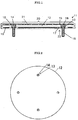
- Fig. 1 is a cross-section view showing an example of a ceramic heater of the present invention.
- Figs. 2 and 3 are views showing an example of a plate member and a joint member in the ceramic heater of the present invention.
- Figs. 6 and 8 are views showing an example for connecting a conductive member with the joint member in the ceramic heater of the present invention.
- the ceramic heater according to the present invention is a ceramic heater 11 comprising: at least a plate member 12 made of insulating ceramics in which one or more pair(s) of through-holes 13 are formed; a conductive layer 19 made of conductive ceramics formed on the plate member 12; and a coating layer 21 made of insulating ceramics formed on the conductive layer 19; wherein a joint member 14 made of conductive ceramics is inserted into the through-hole 13 of the plate member 12; an end face 16 of the joint member 14 inserted into the through-hole 13 has a same plane with a main surface 15 of the plate member 12 on which the conductive layer 19 is formed; the joint member 14 is coated with the conductive layer 19 and thereby fixed to the plate member 12 and also connected with the conductive layer 19 having a heater pattern 20 formed on a main surface 15 of the plate member 12; and a side of the joint member 14 opposite to a side thereof inserted into the through-hole 13 of the plate member 12 projects from the plate member 12 and the projecting portion 18 constitutes a terminal
- an end face 16 of the joint member has a same plane with a main surface 15 of the plate member 12 and is connected with the conductive layer 19 having a heater pattern 20 formed on the main surface 15 of the plate member 12, it is not necessary the positions in which the joint members 14 are provided are made to be outside the region on the plate member 12 on which an object to be heated is put, and can be set to discretionary positions inside the region. Therefore, it becomes possible that the ceramic heater is smaller in size than a conventional heater and is flat without projection on the heating surface of the heater.
- the heater pattern 20 formed on the same plane, an object to be heated being put directly on the flat heater can be uniformly heated with high heating efficiency.
- the heater pattern 20 is also formed on the end face 16 of the joint member.
- the heater is difficult from a conventional heater as shown in Fig. 10 , and the joint members 14 to be connected to the first heating region 2 can be provided in the first heating region 2. Therefore, it is not necessary that the conductive pathways connecting the first heating region 2 and the joint members 14 are provided in the second heating region 3. Therefore, in the case of two-zone system, it is possible that the ceramic heater can have better heating uniformity (see, Fig. 4 ).
- the joint member 14 projects from the plate member 12 and the projecting portion 18 constitutes a terminal on which the coating layer 21 is not formed
- the joint member can be connected to a conductive member having a concave portion, for example, a conductive member 34 with a rod shape as shown in Figs. 6 and 8 , and the conductive member can be exchanged if damaged. Therefore, the operating life of the heater becomes long.
- the joint member 14 is coated with the conductive layer 19 and thereby fixed to the plate member 12, contact of the conductive layer 19 and the joint member 14 is good and the durability is enhanced without using a screw or the like that is easily damaged by the heater heat and the heater weight and so forth, and the operating life of the heater can be long.
- the joint member 14 is pressed-fit into the through-hole 13 of the plate member 12.
- a screw that causes a trouble of breaking due to the magnitude of the heater heat and the large load in heater weight and so forth is not used for connecting the plate member and the joint member. Therefore, the contact of the conductive layer and the joint member can be maintained to be good for a long time, and the ceramic heater comes to be capable of being used stably and to have a long operating life.
- the joint member 14 when the joint member 14 is pressed-fit into the through-hole 13 of the plate member 12, the joint member 14 is not required to be thick for the purpose of preventing a trouble in screw ridge and therefore can be small in cross-section area thereof. Therefore, amount of heat to outflow to the outside can be suppressed to small and the object to be heated can be heated uniformly with higher heating efficiency.
- the heater because it is not necessary to use a bolt and a nut being a source origin of particles, there is no scattering of impurities and the heater is applicable to heating process in which high purity is required.
- flat-surface processing is performed by flat-surface grinding of the main surface or the like so that the end face 16 of the joint member and the main surface 15 of the plate member have an accurately same plane.
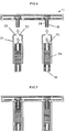
- the projecting portion 18 of the joint member 14 is inserted into a concave portion 35 provided in one end of a conductive member 34 with a rod shape made of conductive ceramics that is a separate member from the joint member 14, and thereby connected with the conductive member (see, Figs. 7 and 9 ).
- a power terminal 36 for being connected with a conductive wire or the like is provided in the other end opposite to the one end in which the concave portion 35 of the conductive member with a rod shape is provided, and thereby, there is a sufficient distance between the power terminal and the heater main body. Therefore, the temperature is low at the power terminal 36 for being connected with the conductive wire or the like. Degradation due to the heater heat of such a member as a crimping terminal or a bolt or a screw or a nut or the like which is used in the connection, and scattering of particles due thereto, can be suppressed.
- the conductive member 34 is a separate member from the heater main body, in the case that the conductive member 34 is damaged, it is sufficient that only the member is exchanged, and therefore, the heater can come to have a long operating life.
- a male screw is formed on the projecting portion 18, a female screw is formed on the concave portion 35 of the conductive member 34, the male screw is screwed together to the female screw, and thereby the projecting portion 18 of the joint member 14 is connected to the conductive member.
- the electric connection can be assured, and the member exchange is easy in the case that the conductive member or the protection layer formed thereon is damaged. Assembly thereof is easy and space is not wasted in storage or transportation, and therefore the heater can be high in convenience.
- the joint member 14 is sufficient as long as made of conductive ceramics, and however is preferably made of any one of, graphite, sintered silicon carbide, and sintered boron carbide. Thereby, the joint member becomes excellent in heat resistance and additionally the outer face in the upper side thereof are coated with the conductive layer 19 and the coating layer 21, and therefore, there is no scattering of impurities and therefore the heater is applicable to heating process in which high purity is required.
- graphite is more preferable because it is relatively inexpensive and easy to be processed.
- the shape of the joint member 14 is a bolt shape having a cylindrical shape as shown in Figs. 1 , 6 , 8 , and 12 .
- the shape is not limited thereto and is sufficient as long as a shape being capable of being inserted into the through-hole 13 and fixed.
- the diameter of the joint member 14 is not particularly limited. However, the diameter of the portion inserted to the through-hole 13 may be 3-20 mm, and more preferably, 8-14 mm. If the diameter is larger than 3 mm, the joint member is difficult to break. If the diameter is smaller than 20 mm, outflow of heat to the outside from the joint member 14 is small and temperature distribution of the heater becomes uniform.
- the plate member 12 is sufficient as long as being made of insulating ceramics in which one or more pair(s) of through-holes 13 are formed and functioning as a supporting substrate on which the heater pattern 20 is formed.
- the plate member is made of any one of pyrolytic boron nitride, pyrolytic boron nitride containing carbon, pyrolytic boron nitride containing silicon, and pyrolytic boron nitride containing aluminum.
- the plate member 12 can be produced by chemical vapor deposition method and has a high insulating property and there is no scattering of impurities due to use at a high temperature, and therefore is applicable to heating process in which high purity is required.
- the plate member can be also used stably in a high-temperature process in the vicinity of 1500°C and additionally at a rapidly rising or falling temperature of 100 °C/min or more.
- thickness of the plate member 12 is 1-5 mm, and more preferably, 2-4 mm. In the case that the thickness of the plate member 12 is thinner than 1 mm, warpage is not caused. Moreover, in the case that the thickness is thinner than 5 mm, the difference between thermal expansion amount in the thickness direction of the plate member 12 and thermal expansion amount of the joint member 14 does not become too large, and at the press-fit part, crack or delamination is not generated in the conductive layer 19 made of conductive ceramics or the coating layer 21.
- the plate member 12 is made of pyrolytic boron nitride containing carbon or pyrolytic boron nitride containing silicon or pyrolytic boron nitride containing aluminum, resistivity of the plate member becomes smaller as the carbon content or the silicon content or the aluminum content becomes larger. It is necessary that the carbon content or the silicon content or the aluminum content is suppressed to amount by which insulation can be held at gaps of the heater pattern.
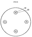
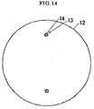
- the shape of the plate member 12 is a disc-like shape as Figs. 2 , 4 , and 14 for supporting a semiconductor wafer having a circular shape with a large diameter as an object to be heated.
- it may be a polygonal plate shape according to need.
- the through-holes 13 are formed by one or more pair(s).
- two pairs are formed as Figs. 2 and 5 .
- the shape of the through-hole 13 is not particularly limited as long as a shape being capable of inserting the joint member 14 thereinto and fixing it thereto.
- a circular shape being capable of pressing-fit and fixing the joint member 14 with a cylindrical shape thereto is preferable.
- the conductive layer 19 is made of conductive ceramics and coats and fixes the plate member 12 and the joint member 14 inserted into the through-hole 13 therein. Thereby, the joint member 14 and the plate member 12 can be fixed, and the electric contact of the conductive layer and the joint member can be good.
- the conductive layer 19 is made of any one of pyrolytic graphite and pyrolytic graphite containing boron and/or boron carbide.
- the heater can be stably used until a high temperature, and the conductive layer is easier to be processed than metal foil or rolled circuit and therefore it becomes easy that as the heater pattern having meandering pattern, width and thickness thereof are changed and thereby to make a discretionary temperature gradient therein or to make a heating distribution therein according to the heat environment to uniform heat.
- the thickness of the conductive layer can be more uniform, compared to a method of coating a conductive paste by screenprinting.
- the thickness of the conductive layer 19 is not particularly limited. However, it is desirable that the thickness is 10-300 ⁇ m and particularly 30-150 ⁇ m. It is sufficient that an appropriate thickness is selected well-considering the relation of the electric capacity or the shape of the heater pattern 20 for making the heater temperature reach an objective temperature and uniformizing heat.
- the heater pattern 20 can be formed, for example, by machining. However, as shown in Fig. 1 , the heater pattern 20 can be formed on the main surface 15 of the plate member of the same plane made by the end face 16 of the joint member 14 opposite to the side having the projecting portion 18 therein and the main surface 15 of the plate member. In this case, the heater pattern can also be formed on the end face 16 of the joint member as described above. By such a heater pattern 20, an object to be heated can be heated uniformly with high heating efficiency.
- the heater pattern 20 may be formed on a main surface 17 opposite to the main surface 15, or formed on both of the main surface 15 and the main surface 17.
- the heater pattern can be designed according to flatness for putting an object to be heated and necessary heat amount and so forth.
- the joint members are electrically insulated not to be short-circuited to each other.
- the electrical insulating can be performed by forming a removal part of the conductive layer by providing a groove 22 in the back surface thereof or the like.
- the heater pattern 20 is formed as a two-zone system so that one pair of the joint members can supply current in the pattern forming the first heating region 2 shown as the inner white part and so that the other pair of the joint members 14 can supply current in the pattern forming the second heating region 3 shown as the outer gray part.
- the conductive member 34 is sufficient as long as being provided with a concave portion 35 into which the projecting portion 18 of the joint member 14 is inserted.
- the conductive member is made of any one of, graphite, graphite coated with pyrolytic graphite containing boron and/or boron carbide on an outer surface thereof, conductive sintered silicon carbide, conductive sintered boron carbide, tantalum, tungsten, molybdenum, inconel, nickel, and stainless.
- the heater becomes applicable to a heating process of 1000°C or more because conductivity of the conductive member 34 is high and additionally melting point thereof is high.
- graphite is more preferable because it is relatively inexpensive and easy to be processed.
- the conductive member 34 is surrounded by a tubular member 31 made of insulating ceramics as shown in Fig. 6 .
- a tubular member 31 made of insulating ceramics as shown in Fig. 6 .
- the tubular member 31 has a bottom 32 in one end thereof and is provided with a through-hole 33 in a central part of the bottom, a bottom face of the bottom 32 is in contact with a heater main body, the projecting portion 18 of the joint member 14 is inserted into the through-hole 33, further the conductive member 34 is inserted into the tubular member, and thereby the tubular member can surround the conductive member 34.
- the surrounding of the conductive bodies by the insulating ceramics in the vicinity of the heater main body can be certainly performed. Scattering of impurities or particles due to degradation by the heater heat can be suppressed certainly.
- a protection layer 37 made of insulating ceramics is formed on the conductive member 34.
- a protection layer 37 made of insulating ceramics is formed on the conductive member 34.
- the heater becomes being capable of being used under an atmosphere being reactive with the joint member 14 or the conductive member 34. Electric discharge, heater damage, or scattering of impurities or particles which is caused by corrosion by the reactive atmosphere can be suppressed effectively.
- the conductive member is made of graphite or sintered silicon carbide or sintered boron carbide that is conductive ceramics and the protection layer made of insulating ceramics is formed thereon because at a higher temperature, the conductive member is stable and scattering of impurities is small.
- the coating layer 21, the tubular member 31, or the protection layer 37 on the conductive member is made of any one of, pyrolytic boron nitride, pyrolytic boron nitride containing carbon, pyrolytic boron nitride containing silicon, and pyrolytic boron nitride containing aluminum.
- pyrolytic boron nitride pyrolytic boron nitride containing carbon
- pyrolytic boron nitride containing silicon pyrolytic boron nitride containing aluminum.
- pyrolytic boron nitride containing aluminum As described above, they can be easily produced by chemical vapor deposition method. And, even when used at a high temperature, the heater is stable and causes no scattering of impurities, and therefore, the heater also becomes applicable to heating process in which high purity is required.
- the coating layer 21 or the tubular member 31 or the protection layer 37 on the conductive member is made of pyrolytic boron nitride containing carbon or pyrolytic boron nitride containing silicon or pyrolytic boron nitride containing aluminum
- the resistivity becomes smaller as the carbon content or the silicon content or the aluminum content becomes larger.
- the carbon content or the silicon content or the aluminum content is required to be suppressed to amount by which insulation can be held at gaps of the heater pattern or between the heater pattern and the object to be heated.
- the tubular member 31 or the protection layer 37 on the conductive member it is required to be suppressed to amount by which insulation can be held between the conductive member and a peripheral member thereof.
- the ceramic heater according to the present invention as described above, on the surface side on which the end face 16 of the joint member 14 has the same plane with the main surface 15 of the plate member 12 and on which the heater pattern 20 is formed, an object to be heated such as a semiconductor wafer with a large diameter is directly put, and electric power is supplied from the power-supply terminal 18, and thereby, the objected to be heated can be heated uniformly with high heating efficiency although the heater main body does not become large in size and has a compact structure. And, because scattering of impurities or particles is small, contamination to the object to be heated is small and the operating life of the heater is long.
- the ceramic heater according to the present invention as described above can be produced by a method for producing a ceramic heater 11, comprising steps of:
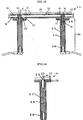
- Fig. 12 is a cross-section view showing an example of another shape of the ceramic heater of the present invention.
- Fig. 13 is a cross-section view showing an example of the heater power-supply component of the present invention.
- the ceramic heater 11 includes a heater power-supply component 30 that is connected to the projecting portion of the joint member 14 and that is a separate member from the joint member 14;
- the heater power-supply component 30 includes, a conductive member 34 with a rod shape made of conductive ceramics having a concave portion 35 in one end thereof that the projecting portion 18 of the joint member is inserted into and connected with and having a power terminal 36 in another end thereof to be connected to a power source, and a protection layer 37 made of insulating ceramics provided on an outer surface of the conductive member 34; and a distance d from an outermost part 27 of an end face 23 in the one end that the joint member 14 is connected with to the concave portion 35 therein is 3 mm or more.
- the heater includes a heater power-supply component 30 that is connected to the projecting portion 18 of the joint member 14 and that is a separate member from the joint member 14, the heater becomes difficult to be damaged.
- the heater power-supply component 30 or particularly a protection layer 37 provided therein is damaged, only the component can be exchanged. Therefore, the operating life of the heater can be long and the production cost can be reduced.
- the heater power-supply component 30 includes the conductive member 34 made of conductive ceramics having a concave portion 35 in one end thereof that the projecting portion 18 of the joint member is inserted into and connected with and having a power terminal 36 in another end thereof to be connected to a power source and the protection layer 37 made of insulating ceramics provided on an outer surface of the conductive member, the conductive member 34 made of conductive ceramics is protected from the process gas by the protection layer made of insulating ceramics.
- the conductive member 34 of the heater power-supply component 30 has a rod shape, there is a sufficient distance between the power terminal 36 that is the junction with a conductive wire or the like and the heater main body 11. Therefore, the temperature is low at the junction with a conductive wire or the like. Degradation of such a member as a crimping terminal or a bolt or a screw or a nut or the like which is used in the connection, and scattering of particles due thereto, can be suppressed.
- the heater power-supply component 30 has a distance d from an outermost part 27 of an end face 23 in the one end that the joint member 14 is connected with to the concave portion 35 therein that is 3 mm or more, in the case of using a gas reacting with the conductive ceramics at a high temperature as a process gas, by performing the connection so that the protection layer 37 on the end face 23 in the one end of the heater power-supply component 30 connected with the joint member 14 and the coating layer 21 of the ceramic heater main body 11 are attached firmly, a gap between the protection layer 37 and the coating layer 21 is made to almost completely disappear and the process gas is insulated.
- the conductive ceramics of the projecting portion 18 and the concave portion 35 can be prevented from being wasted by invasion of the process gas. Furthermore, thereby, abnormal generation of heat in the junction and further generation of electric discharge can be prevented and supply of current in the junction can be assured.
- the distance d is 6 mm or more. And, 10 mm or more is more preferable because a gap that the process gas can invade can be made to completely disappear. Moreover, 20 mm or less is preferable because material of the member is not wasted and the cost is low.
- the heater power-supply component 30 has a guard portion 28 in the one end that the joint member 14 is connected with. Thereby, the end face 23 of the one end that the joint member 14 is connected with can be easily broadened and a distance d from an outermost part 27 of an end face 23 to the concave portion 35 therein can be set to be 3 mm or more.
- the portion having the power terminal 36 except the guard portion 28 has a thin rod shape, amount of heat to outflow to the outside through the heater power-supply component 30 from the heater can be small, and therefore, the heating uniformity of the heater can be improved.
- the diameter of the guard portion 28 can be set to be 10 mm to 50 mm and the diameter of the rod portion except the guard portion 28 can be set to be 7 mm to 20 mm.
- the concave portion 35 of the heater power-supply component 30 an exposed portion on which the protection layer 37 is not formed for the electrical connection with the projecting portion 18 of the joint member.
- the size of the concave portion 35 is required to be a size being capable of inserting and connecting the projecting portion 18 of the joint member thereto.
- the size of the concave portion 35 can be 2-5 mm.
- the conductive member 34 of the heater power-supply component 30 is sufficient as long as made of conductive ceramics.
- the conductive member is made of any one of, graphite, sintered silicon carbide, and sintered boron carbide.
- conductivity thereof is high and additionally the melting point is high, and therefore, heat resistance thereof becomes excellent, and additionally, scattering of impurities is small, and therefore the heater becomes stably applicable to heating process of 1000°C or more in which high purity is required.
- graphite is more preferable because it is relatively inexpensive and easy to be processed.
- the protection layer 37 of the heater power-supply component 30 is made of insulating ceramics, scattering of impurities or particles from the heater power-supply component 30 can be suppressed, and in the heater, the heater power-supply component 30 is insulated from a peripheral member thereof, and therefore, electric discharge between the heater power-supply component 30 and the peripheral member can be prevented.
- the heater becomes being capable of being used under the process gas being reactive with the joint member 14 or the conductive member 34 of the heater power-supply component 30. Electric discharge, heater damage, or scattering of impurities or particles which is caused by corrosion by the reactive atmosphere can be suppressed effectively.
- a material of such a protection layer 37 is made of any one of, pyrolytic boron nitride, pyrolytic boron nitride containing carbon, pyrolytic boron nitride containing silicon, and pyrolytic boron nitride containing aluminum.
- the conductive member 34 can be protected from corrosion due to the process gas, and also, it is easily produced by chemical vapor deposition method.
- the heater can be stably used and causes no scattering of impurities, and therefore, the heater also becomes applicable to heating process in which high purity is required.
- the thickness of the protection layer 37 is not particularly limited. However, it is desirable that the thickness is 20-300 ⁇ m and particularly 50-200 ⁇ m. If thicker than 20 ⁇ m, there is not a risk of dielectric breakdown, and if thinner than 300 ⁇ m, delamination or the like is not caused.
- the protection layer 37 is made of pyrolytic boron nitride containing carbon or pyrolytic boron nitride containing silicon or pyrolytic boron nitride containing aluminum
- the resistivity becomes smaller as the carbon content or the silicon content or the aluminum content becomes larger. Therefore, the carbon content or the silicon content or the aluminum content is required to be suppressed to amount by which insulation can be held between the power-supply component and a peripheral member thereof.
- a female screw is formed on the concave portion and a male screw is formed on the projecting portion 18 of the joint member 14 and the male screw is screwed together to the female screw and thereby the concave portion 35 of the heater power-supply component 30 is connected to the joint member.
- the portions of the female screw and the male screw are not degraded with being exposed directly to a reactive atmosphere, and the electric contact can be assured.
- the heater power-supply component 30 or particularly a protection layer 37 provided therein is damaged, only the component can be exchanged. Therefore, the operating life of the heater can be long and the production cost can be reduced.
- the heater can be high in convenience.
- the protection layer 37 and the coating layer 21 can be firmly attached solidly, and insulating effect of the process gas is high.
- the heater power-supply component 30 of the present invention has a distance from an outermost part 27 of an end face 23 in the one end that the projecting portion 18 of the joint member 14 is connected with to the concave portion 35 therein that is 3 mm or more, by performing the connection so that the protection layer 37 on the end face 23 in the one end of the heater power-supply component 30 and the coating layer 21 of the ceramic heater main body 11 are attached firmly, the process gas is difficult to reach the conductive ceramics of the projecting portion 18 and the concave portion 35. Therefore, the conductive ceramics of the projecting portion 18 and the concave portion 35 is not wasted, and the operating life of the heater is very long.
- the heater power-supply component 30 of the present invention is connected to the main body of the ceramic heater 11 of the present invention.
- the present invention is not necessarily limited to the component connected to the projecting portion 18 of the joint member 14 of the main body of the ceramic heater 11.
- the power-supply component to be connected to a joint terminal of a main body of a general ceramic heater is possible, and thereby, the junction can be difficult to be invaded.
- the plate member made of pyrolytic boron nitride having a diameter of 310 mm and a thickness of 2.5 mm was produced by reacting 4 SLM of ammonium and 2 SLM of boron trichloride under a pressure of 10 Torr at a temperature of 1850°C.
- the through-holes having a diameter of 12 mm were provided in two places on a 102 mm radius from the center of this plate member and in two places on a 111 mm radius therefrom.
- the conductive layer made of a pyrolytic graphite containing boron carbide having a thickness of 50 ⁇ m was provided by pyrolyzing 3 SLM of methane and 0.1 SLM of boron trichloride under a pressure of 5 Torr at a temperature of 1750°C, the heater pattern as Fig. 4 was formed by machining therein, and thereby, this was made to be a ceramic heater having two-zone system.
- the first heating region in the central part of the heater and the second heating region located in the outside thereof were divided at the part of a 108.8 mm radius as shown as "A" in Fig. 4 .
- the first heating region had an almost concentric-circle shape and the second heating region had a ring shape.
- the conductive layer formed on the back surface was partially removed by subjecting the surrounds of the joint members to machining as shown in Fig. 5 . Furthermore, on the ceramic heater, the plate member and the joint members and the conductive layer except the projecting portion 18 of the joint member 14 were integrally coated with an insulator film made of pyrolytic boron nitride by reacting 5 SLM of ammonium and 2 SLM of boron trichloride under the condition of a pressure of 10 Torr and a temperature of 1890°C, and thereby, a ceramic heater for heating a semiconductor wafer having a large diameter of 300 mm (12 inches) as shown in Fig. 1 was completed.
- This heater was set to a vacuum chamber and a thermocouple for measuring temperature was attached to the heater and then pressure inside the chamber was depressurized to 5 Pa with a vacuum pump. Then, current was supplied in this heater and a heat cycle examination was performed. With setting the temperature rising rate to 150 °C/min and the temperature falling rate to 100 °C/min, rising and falling of the temperature could be repeated between 300-1100°C by 500 times with no problem. After the heat cycle examination, the ceramic heater was gotten out of the vacuum chamber and the appearance thereof was confirmed. Therefore, abnormality such as crack or delamination was not observed on the insulator film.
- the coating layer made of a pyrolytic boron nitride with a thickness of 200 ⁇ m by reacting 5 SLM of ammonium and 2 SLM of boron trichloride under the condition of a pressure of 10 Torr and a temperature of 1890°C. Then, the female screw of M6 was formed on one end of the conductive member, and on the other end thereof, a female screw of M6 was formed in the same manner for being connected to a conductive wire from a power source.
- the conductive member was connected to the above-described main body of the ceramic heater 11 of the present invention, and thereby, the heater as shown in Fig. 9 was completed.
- This was set in a chamber, and a thermocouple for measuring temperature was attached to the heater, and a silicon wafer with a diameter of 300 mm was put on the heater. Then, 6 Vol%H 2 /Ar was supplied at a flow amount of 200 ml/min.
- the ceramic heater according to the present invention even if it is a heater for heating a semiconductor wafer having a large diameter of 300 mm (12 inches), it is not necessary that the positions in which the joint members are provided are made to be outside the region on the plate member on which a semiconductor wafer is put, and therefore, it has become possible that by the heater having the heater main body does not become large in size and has a compact structure whose diameter is only approximately 310 mm, an object to be heated is heated uniformly with high heating efficiency and scattering of impurities is not caused in the heating, and therefore the heater also becomes applicable to heating process in which high purity is required.
- the plate member made of pyrolytic boron nitride having a diameter of 310 mm and a thickness of 2.5 mm was produced by reacting 4 SLM of ammonium and 2 SLM of boron trichloride under a pressure of 6 Torr (800 Pa) at a temperature of 1850°C.
- the through-holes having a diameter of 12 mm were provided in two places on a 130 mm radius from the center of this plate member.
- a conductive layer made of pyrolytic graphite containing boron carbide having a thickness of 50 ⁇ m was provided by pyrolyzing 3 SLM of methane and 0.1 SLM of boron trichloride under a pressure of 5 Torr (667 Pa) at a temperature of 1750°C, and by machining therein, a ceramic heater having one-zone system was produced.
- the conductive layer formed on the back surface was partially removed by subjecting only vicinities of the joint members to machining so that the joint members are electrically insulated not to be short-circuited to each other.
- the plate member and the joint members and the conductive layer except the projecting portion 18 of the joint member 14 were integrally coated with an insulator film made of pyrolytic boron nitride by reacting 5 SLM of ammonium and 2 SLM of boron trichloride under the condition of a pressure of 10 Torr (1333 Pa) and a temperature of 1890°C, and thereby, the ceramic heater main body as shown in Fig. 1 was completed.
- the protection layer made of pyrolytic boron nitride with a thickness of 200 ⁇ m by reacting 5 SLM of ammonium and 2 SLM of boron trichloride under the condition of a pressure of 5 Torr (667 Pa) and a temperature of 1890°C.
- the female screw of M5 was formed on one end of the conductive member, and on the other end thereof, a female screw of M5 was formed in the same manner for being connected to a conductive wire from a power source, and thereby, the heater power-supply component was completed.
- the distance d from an outermost part of the end face having a diameter of 30 mm to the concave portion on which the female screw was formed was approximately 12.5 mm.
- the heater power-supply component was connected to the main body of the ceramic heater of the present invention of Fig. 1 , and thereby, the heater as shown in Fig. 12 was completed. This was set in a chamber, and a thermocouple for measuring temperature was attached to the heater, and a silicon wafer with a diameter of 300 mm was put on the heater. Then, 6 Vol%H 2 /Ar was supplied at a flow amount of 200 ml/min.
- the heater power-supply component was detached. And, the concave portion of the heater power-supply component and the joint terminal portion of the projecting portion were confirmed. However, abnormality in appearance was not observed in the screw.
- the ceramic heater according to the present invention it is not necessary that the positions in which the joint members are provided are made to be outside the region on the plate member on which a semiconductor wafer is put, and therefore, it has become possible that by the heater having the heater main body does not become large in size and has a compact structure, an object to be heated is heated uniformly with high heating efficiency and scattering of impurities is not caused in the heating, and therefore the heater also becomes applicable to heating process in which high purity is required.
- the conductive members with a rod shape made of graphite (manufactured by Toyo Tanso Co., Ltd., IG-110) having a guard portion with a diameter of 11 mm (Example 3) and 15 mm (Example 4) and 25 mm (Example 5) were used, the heater power-supply components so as to respectively have the distances d of approximately 3 mm, approximately 5 mm, and approximately 10 mm, were produced. Then, they were connected to the main bodies of the ceramic heaters of the present invention of Fig. 1 in the same manner with Example 2, and thereby the ceramic heaters as shown in Fig. 12 were completed.
- the continuous heating examinations of the heaters were performed at 1100°C for 500 hr. Electric discharge or breaking was not generated on the way. It was possible that the continuous heating examinations were performed for 500 hr with no problem.
- the plate member made of pyrolytic boron nitride having a diameter of 350 mm that is larger than that of Example and having a thickness of 2.5 mm was produced by reacting 4 SLM of ammonium and 2 SLM of boron trichloride under a pressure of 10 Torr at a temperature of 1850°C.
- the conductive layer made of pyrolytic graphite containing boron carbide having a thickness of 50 ⁇ m was provided by pyrolyzing 3 SLM of methane and 0.1 SLM of boron trichloride under a pressure of 5 Torr at a temperature of 1750°C, the heater pattern having a conductive pathways 6 with two-zone system as Fig. 10 was formed by machining therein.
- the plate member and the graphite rod members and the graphite screws were integrally coated with an insulator film made of pyrolytic boron nitride by reacting 5 SLM of ammonium and 2 SLM of boron trichloride under the condition of a pressure of 10 Torr and a temperature of 1890°C, and thereby, the ceramic heater was completed.
- this heater was difficult to be handled, and the graphite rod member was occasionally damaged by mistake before the heater was set to a chamber.
- the heater main body in itself was not damaged, the damaged graphite cylinder could not be exchanged because the graphite rod member and the heater main body were integrally coated with the insulating film. Therefore, the heater could not be attached to the chamber and therefore the heating examination could not be performed.
- the surface was not flat due to the screws, and therefore, for heating the wafer with a diameter of 300 mm, the heater had to have a large size with a diameter of approximately 350 mm, and the power terminal had to be formed in the peripheral part thereof, and this caused cost rise. Furthermore, the conductive pathways 6 were required and also temperature distribution in the wafer plane was bad.
- the plate member made of pyrolytic boron nitride having a diameter of 350 mm that is larger than that of Example and having a thickness of 2.5 mm was produced by reacting 4 SLM of ammonium and 2 SLM of boron trichloride under a pressure of 6 Torr (800 Pa) at a temperature of 1850°C.
- the conductive layer made of pyrolytic graphite containing boron carbide having a thickness of 50 ⁇ m was provided by pyrolyzing 3 SLM of methane and 0.1 SLM of boron trichloride under a pressure of 5 Torr (667 Pa) at a temperature of 1750°C, and the heater pattern was formed by machining therein.
- the plate member and the graphite rod members and the graphite screws were integrally coated with an insulator film made of pyrolytic boron nitride by reacting 5 SLM of ammonium and 2 SLM of boron trichloride under the condition of a pressure of 5 Torr (667 Pa) and a temperature of 1890°C, and thereby, the ceramic heater was completed.
- this heater was difficult to be handled, and the graphite rod member was occasionally damaged by mistake before the heater was set to a chamber.
- the heater main body in itself was not damaged, the damaged graphite cylinder could not be exchanged because the graphite rod member and the heater main body were integrally coated with the insulating film. Therefore, the heater could not be attached to the chamber and therefore the heating examination could not be performed.
Landscapes
- Engineering & Computer Science (AREA)
- Manufacturing & Machinery (AREA)
- Microelectronics & Electronic Packaging (AREA)
- Chemical & Material Sciences (AREA)
- Ceramic Engineering (AREA)
- Resistance Heating (AREA)
Claims (33)
- Keramik-Heizer (11) umfassend: mindestens
ein aus isolierenden Keramiken hergestelltes Plattenelement (12), in dem ein oder mehrere Paar(e) von Durchgangslöchern (13) gebildet sind;
eine aus leitfähigen Keramiken hergestellte leitfähige Schicht (19), die auf dem Plattenelement (12) gebildet ist; und
eine aus isolierenden Keramiken hergestellte Deckschicht (21), die auf der leitfähigen Schicht (19) gebildet ist;
wobei ein aus leitfähigen Keramiken hergestelltes Verbindungselement (14) in das Durchgangsloch (13) des Plattenelements (12) eingefügt ist;
eine Endfläche (16) des in das Durchgangsloch (13) eingefügten Verbindungselements (14), eine gleiche Fläche mit einer Hauptoberfläche (15) des Plattenelements (12), auf dem die leitfähige Schicht (19) gebildet ist, aufweist;
das Verbindungselement (14) mit der leitfähigen Schicht (19) beschichtet ist und dadurch an das Plattenelement (12) fixiert ist und auch mit der leitfähigen Schicht (19) verbunden ist, die ein Heizmuster (20), das auf einer Hauptoberfläche (15) des Plattenelements (12) gebildet ist, aufweist; und
eine Seite des Verbindungselements (14) auf der gegenüber liegenden Seite davon, eingesetzt in das Durchgangsloch (13) des Plattenelements (12), aus dem Plattenelement (12) herausragt und der vorstehende Teil (18) ein Anschlussstück darstellt, auf welchem die Deckschicht (21) nicht gebildet ist. - Keramik-Heizer (11) nach Anspruch 1, wobei das Verbindungselement (14) in das Durchgangsloch (13) des Plattenelements (12) eingepresst ist.
- Keramik-Heizer (11) nach Anspruch 1 oder 2, wobei das Heizmuster (20) auf der Hauptoberfläche (15) des Plattenelements (12) mit der gleichen Fläche mit der Endfläche (16) in der Seite des Verbindungselements (14), das in das Durchgangsloch (13) des Plattenelements (12) eingefügt ist und/oder auf einer Hauptoberfläche (17) auf der gegenüber liegenden Seite der Hauptoberfläche (15), gebildet ist, und in der Hauptoberfläche, auf welcher das Heizmuster (20) nicht gebildet ist, die Verbindungselemente (14) elektrisch isoliert sind, um nicht miteinander kurz geschlossen zu sein.
- Keramik-Heizer (11) nach einem beliebigen der Ansprüche 1 bis 3, wobei das Plattenelement (12) aus einem beliebigen hergestellt ist von pyrolytischem Bornitrid, pyrolytischem Bornitrid enthaltend Kohlenstoff, pyrolytischem Bornitrid enthaltend Silizium, und pyrolytischem Bornitrid enthaltend Aluminium.
- Keramik-Heizer (11) nach einem beliebigen der Ansprüche 1 bis 4, wobei das Verbindungselement (14) aus einem beliebigen von Graphit, gesintertem Siliziumcarbid, und gesintertem Borcarbid hergestellt ist.
- Keramik-Heizer (11) nach einem beliebigen der Ansprüche 1 bis 5, wobei die leitfähige Schicht (19) aus einem beliebigen von pyrolytischem Graphit und pyrolytischem Graphit enthaltend Bor und/oder Borcarbid hergestellt ist.
- Keramik-Heizer (11) nach einem beliebigen der Ansprüche 1 bis 6, wobei der vorstehende Teil (18) des Verbindungselements (14) in einen konkaven Teil (35) eingefügt ist, der an einem Ende eines leitfähigen Elements (34) mit einer Stab-Form, das ein getrenntes Element des Verbindungselements (14) ist und das aus leitfähigen Keramiken oder Metall hergestellt ist, bereitgestellt ist, und dadurch mit dem leitfähigen Element (34) verbunden ist.
- Keramik-Heizer (11) nach einem beliebigen der Ansprüche 1 bis 6, wobei der Keramik-Heizer (11) eine Heiz-Energieversorgungs-Komponente (30) einschließt, die mit dem vorstehenden Teil (18) des Verbindungselements (14) verbunden ist und die ein getrenntes Element des Verbindungselements (14) ist;
die Heiz-Energieversorgungs-Komponente (30) ein leitfähiges Element (34) mit einer Stab-Form, hergestellt aus leitfähigen Keramiken, mit einem konkaven Teil (35) in einem Ende davon, in dem der vorstehende Teil (18) des Verbindungselements (14) eingefügt ist in und verbunden ist mit und aufweist ein Energie-Terminal (36) in einem anderen Ende davon, das mit einer Energiequelle verbunden werden soll, und eine Schutzschicht (37), die aus isolierenden Keramiken hergestellt ist, die auf einer äußeren Oberfläche des leitfähigen Elements (34) bereitgestellt ist, einschließt; und eine Distanz von einem äußersten Teil einer Endfläche (23) in dem einen Ende, mit dem das Verbindungselement (14) verbunden ist, mit dem konkaven Teil (35) darin, 3 mm oder mehr beträgt. - Keramik-Heizer (11) nach Anspruch 8, wobei die Heiz-Energieversorgungs-Komponente (30) einen Schutzteil (28) in dem einen Ende, mit dem das Verbindungselement (14) verbunden ist, aufweist.
- Keramik-Heizer (11) nach einem beliebigen der Ansprüche 7 bis 9, wobei eine Schraube mit Außengewinde auf dem vorstehenden Teil (18) gebildet ist, eine Schraube mit Innengewinde auf dem konkaven Teil (35) des leitfähigen Elements (34) gebildet ist, die Schraube mit Außengewinde mit der Schraube mit Innengewinde zusammen verschraubt ist, und dadurch der vorstehende Teil (18) des Verbindungselements (14) mit dem leitfähigen Element (34) verbunden ist.
- Keramik-Heizer (11) nach einem beliebigen der Ansprüche 7 bis 10, wobei das leitfähige Element (34) aus einem beliebigen von Graphit, Graphit beschichtet mit pyrolytischem Graphit enthaltend Bor und/oder Borcarbid auf einer äußeren Oberfläche davon, gesintertes Siliziumcarbid, gesintertes Borcarbid, Tantal, Wolfram, Molybdän, Inconel, Nickel und Edelstahl hergestellt ist.
- Keramik-Heizer (11) nach einem beliebigen der Ansprüche 7, 10 und 11, wobei das leitfähige Element (34) durch ein rohrförmiges Element (31) umgeben ist, das aus isolierenden Keramiken hergestellt ist.
- Keramik-Heizer (11) nach Anspruch 12, wobei das rohrförmige Element (31) einen Boden (32) in einem Ende davon aufweist und mit einem Durchgangsloch (33) in einem zentralen Teil des Bodens (32) bereitgestellt ist, eine Bodenfläche des Bodens (32), die mit einem Heiz-Hauptkörper in Kontakt ist, der vorstehende Teil (18) des Verbindungselements (14) in das Durchgangsloch (33) davon eingefügt ist, des Weiteren, wobei das leitfähige Element (34) in das rohrförmige Element (31) eingefügt ist, und dadurch das rohrförmige Element (31) das leitfähige Element (34) umgibt.
- Keramik-Heizer (11) nach einem beliebigen der Ansprüche 7, 10 und 11, wobei eine Schutzschicht (37), die aus isolierenden Keramiken hergestellt ist, auf dem leitfähigen Element (34) gebildet ist.
- Keramik-Heizer (11) nach einem beliebigen der Ansprüche 1 bis 14, wobei die Deckschicht (21) des rohrförmigen Elements (31) oder die Schutzschicht (37) auf dem leitfähigen Element (34) aus einem beliebigen von pyrolytischem Bornitrid, pyrolytischem Bornitrid enthaltend Kohlenstoff, pyrolytischem Bornitrid enthaltend Silizium, und pyrolytischem Bornitrid enthaltend Aluminium hergestellt ist.
- Verfahren zum Herstellen eines Keramik-Heizers (11) umfassend mindestens die Schritte:Bilden von einem oder mehreren Paar(en) von Durchgangslöchern (13) in einem Plattenelement (12), das aus isolierenden Keramiken hergestellt ist;Bilden einer leitfähigen Schicht (19), die aus leitfähigen Keramiken hergestellt ist, auf dem Plattenelement (12); und dannBilden einer Deckschicht (21), die aus isolierenden Keramiken hergestellt ist, auf der leitfähigen Schicht (19); wobei ein aus leitfähigen Keramiken hergestelltes Verbindungselement (14) in das Durchgangsloch (13) des Plattenelements (12) eingefügt ist, so dass eine Endfläche (16) des Verbindungselements (14), das in das Durchgangsloch (13) eingefügt, eine gleiche Fläche mit einer Hauptoberfläche (15) des Plattenelements (12) aufweist, und so dass eine Seite des Verbindungselements (14) auf einer gegenüber liegenden Seite davon, in das Verbindungsloch (13) eingefügt ist, aus dem Plattenelement (12) herausragt; dannwird die leitfähige Schicht (19) gebildet, so dass das Verbindungselement (14) und das Plattenelement (12) integral damit beschichtet sind und dadurch das Verbindungselement (14) und das Plattenelement (12) fest fixiert werden;ein Heizmuster (20) wird durch Verarbeiten der leitfähigen Schicht (19) auf einer Hauptoberfläche (15) des Plattenelements (12) gebildet; und dannwird die Deckschicht (21) gebildet, so dass das Plattenelement (12) und das Verbindungselement (14) und die leitfähige Schicht (19) integral damit beschichtet sind, ausgenommen des vorstehenden Teils (18) des Verbindungselements (14).
- Verfahren zum Herstellen eines Keramik-Heizers (11) nach Anspruch 16, wobei das Verbindungselement (14) in das Durchgangsloch (13) des Plattenelements (12) durch Einpressen eingefügt wird.
- Verfahren zum Herstellen eines Keramik-Heizers (11) nach Anspruch 16 oder 17, wobei das Heizmuster (20) auf der Hauptoberfläche (15) des Plattenelements (12) mit der gleichen Fläche mit der Endfläche (16) in der Seite des Verbindungselements (14), das durch das Durchgangsloch (13) des Plattenelements (12) eingefügt ist und/oder auf einer Hauptoberfläche (17) auf der gegenüber liegenden Seite der Hauptoberfläche (15) gebildet wird, und leitfähige Schicht (19) in der Hauptoberfläche, auf welcher das Heizmuster (20) nicht gebildet wird, partiell oder vollständig entfernt wird, so dass die Verbindungselemente (14) elektrisch isoliert sind, um nicht miteinander kurzgeschlossen zu sein.
- Verfahren zum Herstellen eines Keramik-Heizers (11) nach einem beliebigen der Ansprüche 16 bis 18, wobei, als Plattenelement (12), ein beliebiges von pyrolytischem Bornitrid, pyrolytischem Bornitrid enthaltend Kohlenstoff, pyrolytischem Bornitrid enthaltend Silizium, und pyrolytischem Bornitrid enthaltend Aluminium, verwendet wird.
- Verfahren zum Herstellen eines Keramik-Heizers (11) nach einem beliebigen der Ansprüche 16 bis 19, wobei, als Verbindungselement (14), ein beliebiges von Graphit, gesintertem Siliziumcarbid, und gesintertem Borcarbid, verwendet wird.
- Verfahren zum Herstellen eines Keramik-Heizers (11) nach einem beliebigen der Ansprüche 16 bis 20, wobei die leitfähige Schicht (19) durch chemische Gasphasenabscheidung von einem beliebigen von pyrolytischem Graphit und pyrolytischem Graphit enthaltend Bor und/oder Borcarbid gebildet wird.
- Verfahren zum Herstellen eines Keramik-Heizers (11) nach einem beliebigen der Ansprüche 16 bis 21, wobei der vorstehende Teil (18) des Verbindungselements (14) in einen konkaven Teil (35), der an einem Ende eines leitfähigen Elements (34), mit einer Stab-Form, die ein getrenntes Element von dem Verbindungselement (14) ist, gebildet ist und die aus leitfähigen Keramiken oder Metall hergestellt ist, eingefügt wird, und dadurch mit dem leitfähigen Element (34) verbunden wird.
- Verfahren zum Herstellen eines Keramik-Heizers (11) nach Anspruch 22, wobei die Verbindung des vorstehenden Teils (18) des Verbindungselements (14) mit dem leitfähigen Element (34) durchgeführt wird durch Bilden einer Schraube mit Außengewinde auf dem vorstehenden Teil (18) des Verbindungselements (14), Bilden einer Schraube mit Innengewinde auf dem konkaven Teil (35) des leitfähigen Elements (34) und Zusammenschrauben der Schraube mit Außengewinde mit der Schraube mit Innengewinde.
- Verfahren zum Herstellen eines Keramik-Heizers (11) nach Anspruch 22 oder 23, wobei, als leitfähiges Element (34), ein beliebiges von Graphit, Graphit beschichtet mit pyrolytischem Graphit enthaltend Bor und/oder Borcarbid auf einer äußeren Oberfläche davon, gesintertes Siliziumcarbid, gesintertes Borcarbid, Tantal, Wolfram, Molybdän, Inconel, Nickel und Edelstahl, verwendet wird.
- Verfahren zum Herstellen eines Keramik-Heizers (11) nach einem beliebigen der Ansprüche 22 bis 24, wobei das leitfähige Element (34) durch ein rohrförmiges Element, hergestellt aus isolierenden Keramiken, umgeben wird.
- Verfahren zum Herstellen eines Keramik-Heizers (11) nach Anspruch 25, wobei das Umgeben durch das rohrförmige Element (31) durchgeführt wird durch Bilden eines Bodens (32) in einem Ende des rohrförmigen Elements (31), hergestellt aus isolierenden Keramiken, Bereitstellen eines Durchgangslochs (33) in einem zentralen Teil des Bodens (32), Einfügen des vorstehenden Teils (18) des Verbindungselements (14) in das Durchgangsloch (33) davon, In-Kontakt-Bringen einer Boden (32) Fläche des Bodens mit einem Heiz-Hauptkörper und des Weiteren Einfügen und Fixieren des vorstehenden Teils (18) in das leitfähige Element (34).
- Verfahren zum Herstellen eines Keramik-Heizers (11) nach einem beliebigen der Ansprüche 22 bis 24, wobei das leitfähige Element (34), auf einer Oberfläche von welchem, eine aus isolierenden Keramiken hergestellte Schutzschicht (37) gebildet ist, verwendet wird.
- Verfahren zum Herstellen eines Keramik-Heizers (11) nach einem beliebigen der Ansprüche 16 bis 27, wobei als Deckschicht (21) oder als rohrförmiges Element (31) oder als Schutzschicht (37) auf dem leitfähigen Element (34) ein beliebiges von pyrolytischem Bornitrid, pyrolytischem Bornitrid enthaltend Kohlenstoff, pyrolytischem Bornitrid enthaltend Silizium, und pyrolytischem Bornitrid enthaltend Aluminium, verwendet wird.
- Heiz-Energieversorgungs-Komponente (30) umfassend: mindestens ein leitfähiges Element (34) mit einer Stab-Form, hergestellt aus leitfähigen Keramiken mit einem konkaven Teil (35) in einem Ende davon, in den ein Verbindungs-Terminal eines Keramik-Heiz-Hauptkörpers eingefügt und verbunden werden kann und mit einem Energie-Terminal (36) in einem anderen Ende davon, das mit einer Energiequelle verbunden werden soll; und
eine aus isolierenden Keramiken hergestellte Schutzschicht (37), die an einer anderen äußeren Oberfläche des leitfähigen Elements (34) bereitgestellt ist; und wobei eine Distanz von einem äußersten Teil (27) einer Endfläche (23) in dem einen Ende, mit dem das Verbindungs-Terminal verbunden ist, mit dem konkaven Teil (35) darin, 3 mm oder mehr beträgt. - Heiz-Energieversorgungs-Komponente (30) nach Anspruch 29, wobei die Heiz-Energieversorgungs-Komponente (30) einen Schutzteil (28) in dem einen Ende aufweist, mit dem das Verbindungs-Terminal verbunden werden kann.
- Heiz-Energieversorgungs-Komponente (30) nach Anspruch 29 oder 30, wobei das leitfähige Element (34) aus einem beliebigen von Graphit, gesintertem Siliziumcarbid, und gesintertem Borcarbid hergestellt ist.
- Heiz-Energieversorgungs-Komponente (30) nach einem beliebigen der Ansprüche 29 bis 31, wobei die Schutzschicht (37) aus einem beliebigen von pyrolytischem Bornitrid, pyrolytischem Bornitrid enthaltend Kohlenstoff, pyrolytischem Bornitrid enthaltend Silizium, und pyrolytischem Bornitrid enthaltend Aluminium hergestellt ist.
- Heiz-Energieversorgungs-Komponente (30) nach einem beliebigen der Ansprüche 29 bis 32, wobei, auf dem konkaven Teil (35), eine Schraube mit Innengewinde gebildet ist.
Applications Claiming Priority (2)
| Application Number | Priority Date | Filing Date | Title |
|---|---|---|---|
| JP2005355426A JP2007157661A (ja) | 2005-12-08 | 2005-12-08 | セラミックスヒーターおよびセラミックスヒーターの製造方法 |
| JP2006073790A JP2007250403A (ja) | 2006-03-17 | 2006-03-17 | セラミックスヒーターおよびヒーター給電部品 |
Publications (3)
| Publication Number | Publication Date |
|---|---|
| EP1799014A2 EP1799014A2 (de) | 2007-06-20 |
| EP1799014A3 EP1799014A3 (de) | 2008-12-10 |
| EP1799014B1 true EP1799014B1 (de) | 2016-09-14 |
Family
ID=37986793
Family Applications (1)
| Application Number | Title | Priority Date | Filing Date |
|---|---|---|---|
| EP06025034.7A Not-in-force EP1799014B1 (de) | 2005-12-08 | 2006-12-04 | Keramischer Heizer, Verfahren zur Herstellung eines keramischen Heizers und Heizerstromversorgungsbauteil |
Country Status (4)
| Country | Link |
|---|---|
| US (1) | US20070131674A1 (de) |
| EP (1) | EP1799014B1 (de) |
| KR (1) | KR101299495B1 (de) |
| TW (1) | TWI350711B (de) |
Families Citing this family (14)
| Publication number | Priority date | Publication date | Assignee | Title |
|---|---|---|---|---|
| JP4435742B2 (ja) * | 2005-08-09 | 2010-03-24 | 信越化学工業株式会社 | 加熱素子 |
| DE102008062199A1 (de) * | 2008-05-29 | 2009-12-03 | Fraunhofer-Gesellschaft zur Förderung der angewandten Forschung e.V. | Verfahren und Heizeinrichtung zum Thermoformen |
| US10727092B2 (en) * | 2012-10-17 | 2020-07-28 | Applied Materials, Inc. | Heated substrate support ring |
| JP5996519B2 (ja) * | 2013-03-13 | 2016-09-21 | 信越化学工業株式会社 | セラミックヒーター |
| CN104411032A (zh) * | 2014-10-17 | 2015-03-11 | 芜湖市泰能电热器具有限公司 | 一种m型加热铝管 |
| JP2019060819A (ja) * | 2017-09-28 | 2019-04-18 | 日本特殊陶業株式会社 | 電子部品検査装置用配線基板 |
| JP6792539B2 (ja) * | 2017-10-31 | 2020-11-25 | 日本特殊陶業株式会社 | 流体加熱用のセラミックヒータ |
| TWI743446B (zh) * | 2018-02-20 | 2021-10-21 | 美商應用材料股份有限公司 | 用於原子層沉積(ald)溫度均勻性的熱解氮化硼(pbn)加熱器 |
| CN108863443B (zh) * | 2018-07-10 | 2021-05-14 | 山东国晶新材料有限公司 | 一种平面复合加热器的制备方法 |
| US12114402B2 (en) * | 2018-11-19 | 2024-10-08 | Niterra Co., Ltd. | Holding device and method of manufacturing holding device |
| WO2020153218A1 (ja) * | 2019-01-25 | 2020-07-30 | 日本碍子株式会社 | セラミックヒータ及びその製法 |
| KR102352837B1 (ko) * | 2019-07-01 | 2022-01-20 | 주식회사 미코세라믹스 | 세라믹 히터용 접속 부재 |
| US12334341B2 (en) * | 2021-02-11 | 2025-06-17 | Applied Materials, Inc. | Chamber body feedthrough for in chamber resistive heating element |
| JP7514815B2 (ja) * | 2021-12-22 | 2024-07-11 | 日本碍子株式会社 | 半導体製造装置用部材 |
Family Cites Families (18)
| Publication number | Priority date | Publication date | Assignee | Title |
|---|---|---|---|---|
| US5343022A (en) * | 1992-09-29 | 1994-08-30 | Advanced Ceramics Corporation | Pyrolytic boron nitride heating unit |
| JP3560456B2 (ja) * | 1997-12-11 | 2004-09-02 | 信越化学工業株式会社 | 複層セラミックスヒータ |
| JP3477062B2 (ja) * | 1997-12-26 | 2003-12-10 | 京セラ株式会社 | ウエハ加熱装置 |
| JPH11343571A (ja) * | 1998-05-29 | 1999-12-14 | Ngk Insulators Ltd | サセプター |
| JPH11354260A (ja) * | 1998-06-11 | 1999-12-24 | Shin Etsu Chem Co Ltd | 複層セラミックスヒータ |
| JP2001006584A (ja) * | 1999-06-24 | 2001-01-12 | Toshiba Corp | 陰極線管 |
| US6452137B1 (en) * | 1999-09-07 | 2002-09-17 | Ibiden Co., Ltd. | Ceramic heater |
| US6534751B2 (en) * | 2000-02-28 | 2003-03-18 | Kyocera Corporation | Wafer heating apparatus and ceramic heater, and method for producing the same |
| US6960743B2 (en) * | 2000-12-05 | 2005-11-01 | Ibiden Co., Ltd. | Ceramic substrate for semiconductor manufacturing, and method of manufacturing the ceramic substrate |
| US20040175549A1 (en) * | 2001-07-19 | 2004-09-09 | Ibiden Co., Ltd. | Ceramic connection body, method of connecting the ceramic bodies, and ceramic structural body |
| JP4331427B2 (ja) * | 2001-10-03 | 2009-09-16 | 住友電気工業株式会社 | 半導体製造装置に使用される給電用電極部材 |
| EP1463380A1 (de) * | 2001-11-30 | 2004-09-29 | Ibiden Co., Ltd. | Keramisches heizelement |
| US20040074898A1 (en) * | 2002-10-21 | 2004-04-22 | Mariner John T. | Encapsulated graphite heater and process |
| US7364624B2 (en) * | 2003-01-17 | 2008-04-29 | Momentive Performance Materials Inc. | Wafer handling apparatus and method of manufacturing thereof |
| JP4602662B2 (ja) * | 2003-12-01 | 2010-12-22 | 株式会社ブリヂストン | セラミックヒータユニット |
| TWI281833B (en) * | 2004-10-28 | 2007-05-21 | Kyocera Corp | Heater, wafer heating apparatus and method for manufacturing heater |
| JP4435742B2 (ja) * | 2005-08-09 | 2010-03-24 | 信越化学工業株式会社 | 加熱素子 |
| JP2007134088A (ja) * | 2005-11-08 | 2007-05-31 | Shin Etsu Chem Co Ltd | セラミックスヒーターおよびセラミックスヒーターの製造方法 |
-
2006
- 2006-09-12 KR KR1020060088215A patent/KR101299495B1/ko not_active Expired - Fee Related
- 2006-11-02 TW TW095140573A patent/TWI350711B/zh not_active IP Right Cessation
- 2006-12-04 US US11/633,039 patent/US20070131674A1/en not_active Abandoned
- 2006-12-04 EP EP06025034.7A patent/EP1799014B1/de not_active Not-in-force
Also Published As
| Publication number | Publication date |
|---|---|
| TW200735691A (en) | 2007-09-16 |
| KR20070061300A (ko) | 2007-06-13 |
| TWI350711B (en) | 2011-10-11 |
| EP1799014A3 (de) | 2008-12-10 |
| US20070131674A1 (en) | 2007-06-14 |
| EP1799014A2 (de) | 2007-06-20 |
| KR101299495B1 (ko) | 2013-08-29 |
Similar Documents
| Publication | Publication Date | Title |
|---|---|---|
| EP1799014B1 (de) | Keramischer Heizer, Verfahren zur Herstellung eines keramischen Heizers und Heizerstromversorgungsbauteil | |
| EP1784050B1 (de) | Keramisches Heizelement und Verfahren zur Herstellung von keramischen Heizern. | |
| US6242719B1 (en) | Multiple-layered ceramic heater | |
| KR100836183B1 (ko) | 히터 조립체 및 그 설치구조 | |
| KR102087640B1 (ko) | 세라믹 히터 | |
| US9666467B2 (en) | Detachable high-temperature electrostatic chuck assembly | |
| EP0929204B1 (de) | Keramisches Heizelement | |
| US20080190364A1 (en) | Substrate support assembly | |
| KR19980063671A (ko) | 기판의 균일 가열을 위한 기판 지지부재 | |
| US7053339B2 (en) | Ceramic heater | |
| KR101371004B1 (ko) | 가열소자 | |
| KR20120138636A (ko) | 세라믹스 히터 | |
| US20100101494A1 (en) | Electrode and chemical vapor deposition apparatus employing the electrode | |
| JP2786571B2 (ja) | 半導体ウエハー加熱装置 | |
| KR20030032734A (ko) | 반도체 소자 제조장치용 히터 어셈블리 | |
| US20180124873A1 (en) | Heating element | |
| JP2007157661A (ja) | セラミックスヒーターおよびセラミックスヒーターの製造方法 | |
| US20120145701A1 (en) | Electrical resistance heater and heater assemblies | |
| JPH06244143A (ja) | 処理装置 | |
| JP5272485B2 (ja) | 基板支持部材 | |
| US20110064878A1 (en) | Apparatus and method for film deposition | |
| JP3657090B2 (ja) | 加熱体及びこれを用いた半導体製造装置 | |
| JPH11111628A (ja) | シリコン製発熱体及びこれを用いた半導体製造装置 | |
| JP4000236B2 (ja) | セラミックスヒータ | |
| US20010014374A1 (en) | Plasma treatment apparatus and electrode used for the same |
Legal Events
| Date | Code | Title | Description |
|---|---|---|---|
| PUAI | Public reference made under article 153(3) epc to a published international application that has entered the european phase |
Free format text: ORIGINAL CODE: 0009012 |
|
| AK | Designated contracting states |
Kind code of ref document: A2 Designated state(s): AT BE BG CH CY CZ DE DK EE ES FI FR GB GR HU IE IS IT LI LT LU LV MC NL PL PT RO SE SI SK TR |
|
| AX | Request for extension of the european patent |
Extension state: AL BA HR MK YU |
|
| PUAL | Search report despatched |
Free format text: ORIGINAL CODE: 0009013 |
|
| AK | Designated contracting states |
Kind code of ref document: A3 Designated state(s): AT BE BG CH CY CZ DE DK EE ES FI FR GB GR HU IE IS IT LI LT LU LV MC NL PL PT RO SE SI SK TR |
|
| AX | Request for extension of the european patent |
Extension state: AL BA HR MK RS |
|
| 17P | Request for examination filed |
Effective date: 20090310 |
|
| AKX | Designation fees paid |
Designated state(s): DE FR GB |
|
| 17Q | First examination report despatched |
Effective date: 20110404 |
|
| GRAP | Despatch of communication of intention to grant a patent |
Free format text: ORIGINAL CODE: EPIDOSNIGR1 |
|
| INTG | Intention to grant announced |
Effective date: 20160405 |
|
| GRAS | Grant fee paid |
Free format text: ORIGINAL CODE: EPIDOSNIGR3 |
|
| GRAA | (expected) grant |
Free format text: ORIGINAL CODE: 0009210 |
|
| AK | Designated contracting states |
Kind code of ref document: B1 Designated state(s): DE FR GB |
|
| REG | Reference to a national code |
Ref country code: GB Ref legal event code: FG4D |
|
| REG | Reference to a national code |
Ref country code: DE Ref legal event code: R096 Ref document number: 602006050252 Country of ref document: DE |
|
| REG | Reference to a national code |
Ref country code: FR Ref legal event code: PLFP Year of fee payment: 11 |
|
| PGFP | Annual fee paid to national office [announced via postgrant information from national office to epo] |
Ref country code: GB Payment date: 20161130 Year of fee payment: 11 Ref country code: FR Payment date: 20161111 Year of fee payment: 11 |
|
| REG | Reference to a national code |
Ref country code: DE Ref legal event code: R097 Ref document number: 602006050252 Country of ref document: DE |
|
| PLBE | No opposition filed within time limit |
Free format text: ORIGINAL CODE: 0009261 |
|
| STAA | Information on the status of an ep patent application or granted ep patent |
Free format text: STATUS: NO OPPOSITION FILED WITHIN TIME LIMIT |
|
| 26N | No opposition filed |
Effective date: 20170615 |
|
| GBPC | Gb: european patent ceased through non-payment of renewal fee |
Effective date: 20171204 |
|
| REG | Reference to a national code |
Ref country code: FR Ref legal event code: ST Effective date: 20180831 |
|
| PG25 | Lapsed in a contracting state [announced via postgrant information from national office to epo] |
Ref country code: FR Free format text: LAPSE BECAUSE OF NON-PAYMENT OF DUE FEES Effective date: 20180102 |
|
| PG25 | Lapsed in a contracting state [announced via postgrant information from national office to epo] |
Ref country code: GB Free format text: LAPSE BECAUSE OF NON-PAYMENT OF DUE FEES Effective date: 20171204 |
|
| PGFP | Annual fee paid to national office [announced via postgrant information from national office to epo] |
Ref country code: DE Payment date: 20181120 Year of fee payment: 13 |
|
| REG | Reference to a national code |
Ref country code: DE Ref legal event code: R119 Ref document number: 602006050252 Country of ref document: DE |
|
| PG25 | Lapsed in a contracting state [announced via postgrant information from national office to epo] |
Ref country code: DE Free format text: LAPSE BECAUSE OF NON-PAYMENT OF DUE FEES Effective date: 20200701 |