EP1798577A2 - Dispositif électro-optique et méthode d'operation d'un tel dispositif - Google Patents
Dispositif électro-optique et méthode d'operation d'un tel dispositif Download PDFInfo
- Publication number
- EP1798577A2 EP1798577A2 EP06023063A EP06023063A EP1798577A2 EP 1798577 A2 EP1798577 A2 EP 1798577A2 EP 06023063 A EP06023063 A EP 06023063A EP 06023063 A EP06023063 A EP 06023063A EP 1798577 A2 EP1798577 A2 EP 1798577A2
- Authority
- EP
- European Patent Office
- Prior art keywords
- light
- reflector
- detected
- receiver
- störlichtobjekts
- Prior art date
- Legal status (The legal status is an assumption and is not a legal conclusion. Google has not performed a legal analysis and makes no representation as to the accuracy of the status listed.)
- Granted
Links
- 238000000034 method Methods 0.000 title claims abstract description 27
- 230000005693 optoelectronics Effects 0.000 title 2
- 238000001514 detection method Methods 0.000 claims abstract description 91
- 230000002452 interceptive effect Effects 0.000 claims abstract description 37
- 238000011156 evaluation Methods 0.000 claims description 50
- 230000033001 locomotion Effects 0.000 claims description 36
- 230000003287 optical effect Effects 0.000 claims description 16
- 208000004350 Strabismus Diseases 0.000 claims description 11
- 238000003384 imaging method Methods 0.000 claims description 3
- 230000005540 biological transmission Effects 0.000 description 3
- 230000000149 penetrating effect Effects 0.000 description 3
- 238000012935 Averaging Methods 0.000 description 1
- 229910000831 Steel Inorganic materials 0.000 description 1
- 238000013528 artificial neural network Methods 0.000 description 1
- 230000004888 barrier function Effects 0.000 description 1
- 230000008859 change Effects 0.000 description 1
- 230000002999 depolarising effect Effects 0.000 description 1
- 230000006870 function Effects 0.000 description 1
- 238000005286 illumination Methods 0.000 description 1
- 230000036039 immunity Effects 0.000 description 1
- 238000007373 indentation Methods 0.000 description 1
- 239000000463 material Substances 0.000 description 1
- 239000011159 matrix material Substances 0.000 description 1
- 238000012806 monitoring device Methods 0.000 description 1
- 230000010287 polarization Effects 0.000 description 1
- 238000002360 preparation method Methods 0.000 description 1
- 230000008569 process Effects 0.000 description 1
- 230000009467 reduction Effects 0.000 description 1
- 230000004044 response Effects 0.000 description 1
- 239000010959 steel Substances 0.000 description 1
Images


Classifications
-
- G—PHYSICS
- G01—MEASURING; TESTING
- G01V—GEOPHYSICS; GRAVITATIONAL MEASUREMENTS; DETECTING MASSES OR OBJECTS; TAGS
- G01V8/00—Prospecting or detecting by optical means
- G01V8/10—Detecting, e.g. by using light barriers
- G01V8/20—Detecting, e.g. by using light barriers using multiple transmitters or receivers
- G01V8/22—Detecting, e.g. by using light barriers using multiple transmitters or receivers using reflectors
Definitions
- the present invention relates to a method for detecting an object, in which light is emitted by a transmitter in the direction of a reflector, the emitted light is reflected at the reflector and is imaged as a reflector image on a detection range of at least one-dimensionally spatially resolving receiver and detected by this and the detected reflector image is evaluated and an object detection signal is generated when, due to the evaluation of the detected reflector image, an at least partial interruption of the emitted light is detected. Furthermore, the invention is directed to an apparatus for carrying out a corresponding method.
- an object detection signal is generated when the emitted or the reflected light beam is interrupted by an object penetrating into the protected area, so that, for example, the energy detected by the receiver (light intensity, brightness) relative to the detected energy at uninterrupted beam path is reduced by a predetermined threshold.
- the detection area is the area of the receiver on which the reflector image comes to rest when there is no object in the beam path.
- shape, position or special coding of the reflector image can be taken into account.
- the problem here is that an object entering the field of vision of the receiver can reflect or reflect both the light emitted by the transmitter and the light reflected by the reflector, in particular stray light, or other stray light such that the light reflected or reflected from the object Reflected light hits the detection area of the receiver.
- stray light or other stray light such that the light reflected or reflected from the object Reflected light hits the detection area of the receiver.
- a light intensity corresponding to the light intensity with the beam path uninterrupted can be detected, so that erroneously no object detection signal is generated.
- polarization filters are used for optical reduction of the interfering light signals. Since depending on the application, however, the objects interrupting the emitted light beam may also comprise depolarizing or polarization-changing materials, this measure does not always ensure reliable recognition of corresponding objects.
- the described problems occur in particular when the objects have reflective areas.
- the reflective areas occur at inclined surfaces or at radii present on the surface of the object, such as rounded edges, the probability that a light beam reflected on the object hits the receiver is relatively large.
- the light intensity generated by the reflected areas on the receiver in this case is often of the same order of magnitude as the light intensity of the beam path that is not interrupted by the reflector generated reflector image, so that in the energetic evaluation of the reflector image in these cases is erroneously assumed by an uninterrupted beam path.
- this object is achieved in that a detected outside the detection area on the receiver light object of this, examined for given object properties and classified on the basis of the determined object properties as a reflector image or as Störlichtêt that - in the case classification as an interfering light object - a movement of the interfering light object on the receiver is detected and that the generation of the object detection signal is performed in response to the detected movement of the disturbing light object.
- all incident on the receiver light signals eg independent Störlichtsignale, reflected or remitted on an object light signals or reflected light on the reflector light signals.
- the receiver light signals eg independent Störlichtsignale, reflected or remitted on an object light signals or reflected light on the reflector light signals.
- the object detection signal is recognized in the usual way by evaluation of the reflector image.
- the evaluation may be limited to certain properties of the detected reflector image such as brightness, shape, wavelength, pulse frequency or presence of an impressed coding or include a comparison with a predetermined, stored reference reflector image.
- a reflective object comprising a comprehensive object enters a predefined capture region of the device according to the invention, which is defined by a part or the entire field of view of the recipient
- one or more light objects can already be interrupted before the emitted or reflected light beam is interrupted by the article be generated to the recipient. These light objects can arise because, for example, scattered light reflected back from the reflector falls on the penetrating into the capture area object, whereby corresponding light objects are generated on the receiver.
- a predefined area of the receiver forms the detection area.
- the position, size and shape of the detection area can be taught and stored, for example, in a learning process without existing object. This is particularly useful when the detection range is unchangeable during operation, or as an initial detection range after commissioning of a device according to the invention.
- a classification of the light object as a reflector image of the area acted upon by the reflector image of the receiver is set as a detection area. This can change in particular in its position, size or shape, if transmitter, reflector and / or receiver, for example, move due to vibrations against each other in operation.
- the detection area can be determined dynamically on the basis of the detected light object.
- the emitted light can be provided with a code, for example by a coded reflector or filter, and the light object can be examined for the presence of this code in order to determine the object properties. It is also possible that pulsed light is used and to determine the object property, the light object is examined for the presence of the pulse frequency used.
- the determined object properties can be linked together according to given rules. These rules can be realized for example by predetermined algorithms, neural networks or fuzzy logic. Also, a different weighting of the individual object properties is possible.
- object properties can bring about a positive or a negative classification of a light object as a reflector image or as an interfering light object.
- object properties can only be necessary or sufficient criteria for a classification.
- the detected position of a light object on the receiver is a sufficient criterion for classification as an interfering light object if it deviates from the fixed position of the detection area.
- the absence of a code impressed on the emitted light, for example via a coded reflector, or the absence of a predefined pulse frequency can be a sufficient criterion for classification as an interfering light object.
- the evaluation of the reflector image is interrupted when, due to the determined movement of the Störlicht mecanics an imminent or existing, at least partially overlapping the Störlicht suitss with the detection area is detected.
- the detected light object is already examined before it enters the detection area and coincides with it. If the emitted light beam is interrupted by an object, so that initially a light object is generated on the receiver outside the detection area, an object detection signal and, associated therewith, a switching state "object detected" are set due to the interruption.
- the evaluation of the reflector image is interrupted according to the invention. This prevents that due to the Störlicht concernss a supposed non-interruption of the beam path is detected. Since before interrupting the evaluation of the reflector image, the switching state was set to "object detected", this switching state is advantageously maintained even during the interruption of the evaluation of the reflector image.
- an imminent overlap of the Störlichtebenes can be detected with the detection area by evaluating the direction of movement, movement speed and location of the tracked Störlichtêtes.
- the evaluation of the reflector image can be resumed.
- an expected brightness of the interfering light object is subtracted from the brightness detected in the detection area if, due to the detected movement of the interfering light object, an imminent or existing, at least partial overlap of the interfering light object with the detection area is detected , wherein the expected brightness of the Störlichtebenes from the brightness of the Störlicht79es is determined before reaching the detection area.
- the expected brightness of the Störlichtebenes is determined before reaching the detection area.
- the evaluation of the reflector image is not interrupted, but the additional brightness generated by the Störlichtêt is compensated by subtraction. By this compensation is avoided that a falling into the detection area Störlichtaise is incorrectly classified as a reflector image and thus an interruption of the beam path is not detected.
- the movement of the Störlichtebenes is determined by detecting the respective position of the Störlichtsammlunges in temporally successive Ausenseintervallen.
- An imminent overlap of the interfering light object with the detection area is preferably detected if, assuming a constant movement of the interfering light object, this would at least partially fall into the detection area after a predetermined number of evaluation intervals.
- the number of evaluation intervals can be specified depending on the application.
- a light object impinging on the receiver within the detection range is also detected by the receiver, examined for given object properties and classified on the basis of the determined object properties as a reflector image or as an interfering light object.
- the switching state can be set to "no object present", while in the case of a classification as an interfering light object, the evaluation of the detected reflector image can be carried out as already described. For example, an interruption of the evaluation or a subtraction of the brightness of the interfering light object from the total brightness determined in the detection area is also possible in this case.
- a squint angle of the transmitter that is, an angle between the optical axis of the transmitter and the optical axis of the emitted light on the reflector imaging optical element
- a squint angle of the receiver that is an angle between the optical axis of the receiver and the optical axis of an optical element imaging the reflected light on the receiver, compensated by taking into account the position of the reflector image and / or the Störlicht Anlagenes on the receiver.
- the squint angle can be compensated for by software evaluation.
- Fig. 1 shows a transmitter 1 forming a light source, which emits light in the direction of a reflector 2. A section of the emitted light is limited by marginal rays 3, 4 and is directed via a transmission optics 5 to the reflector 2.
- the light represented by marginal rays 6, 7 and reflected by the reflector 2 is imaged by a receiving optical system 8 onto a two-dimensionally spatially resolving receiver 9.
- the receiver can be designed, for example, as a CCD or CMOS matrix or as another suitable receiving element.
- the reflector 2 with the receiving optics 8 is imaged more or less well on the spatially resolving receiver 9, even with different object distances.
- the emitted light can be widened even further than shown in FIG. 1, so that a precise alignment of the transmitter 1 and the transmitting optics 5 to the reflector 2 is not required.
- the widening may also be smaller than shown in FIG. 1 and, in particular, may also be approximately punctiform, so that, for example, a spatial modulation impressed on the transmitted light bundle is imaged on the receiver 9 via the reflector 2 and the receiving optics 8.
- the light according to the present application does not have to be visible light, but electromagnetic waves of very different frequencies can be used, which are suitable for constructing a light barrier.
- Transmitter 1, reflector 2 and receiver 9 and transmitting and receiving optics 5, 8 are each formed according to the electromagnetic waves used.
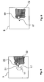
- FIG. 2 schematically shows a top view of the photosensitive surface of the receiver 9.
- a reflector image 11 In the center of the receiver 9 is a reflector image 11, i. that of the receiving optics 8 due to the light reflected on the reflector 2 to the receiver 9 sharp or unsharp image of the reflector 2 shown.
- the illustrated reflector image 11 corresponds to the state shown in Fig. 1, in which neither the emitted light nor the reflected light is interrupted by an object. Through the region of the reflector image 11 in the absence of the object according to FIG. 2, a detection region 23 is thus defined.
- FIG. 3 an object 13 is shown, which moves according to an arrow 14 in the catching area 12.
- the article 13 has a surface with a plurality of bulges and rounded edges 15 and at least partially has a reflective surface.
- the stray light object 20 travels along the arrow 21 on the receiver 9 until the stray light object 20 has fully entered the area of the original reflector image 11, as shown in FIG.
- the remission image of the object 13 forms a second interfering light object 22 on the receiver 9, which is generated by the receiving optics 8 on the receiver 9 due to diffuse reflection of the light impinging on the object 13.
- the Störlichtaise 22 increases in a further movement of the article 13, because also the remission image, i. the interfering light object 22 moves into the center of the receiver 9.
- an object detection signal is generated with the method according to the invention if, due to the evaluation of the actually detected reflector image 11, an interruption of the emitted light is detected. Under emitted light is also the to understand the reflector 2 reflected part of the light.
- the evaluation can include a comparison of the detected brightness, shape, size, position or any other suitable property of the detected reflector image 11 with a correspondingly predetermined value, as it exists in the absence of an object 13 in the beam path.
- light objects 20 impinging on the receiver 9 outside the detection area 23 are detected by the latter and examined for given object properties. If it is detected on the basis of the determined object properties that the detected light object can not be the reflector image 11, the detected light object is classified by a classification unit 24 as an interfering light object 20. Furthermore, the indicated by the arrow 21 movement of the Störlichtebenes 20 on the surface of the receiver 9 continuously or in successive evaluation intervals determined by a motion detection unit 25 and it is checked whether due to the determined movement of an overlap of the Störlichtêtes 20 with the detection area 23 is expected.
- an object detection signal is generated due to the changed shape and / or due to the associated reduced brightness of the detected reflector image 11.
- the associated switching state "object detected” is maintained during the inventive interruption of the evaluation of the reflector image 11 until the interruption of the evaluation of the reflector image 11 is canceled.
- an expected brightness of the interfering light object 20 is subtracted from the brightness detected in the detection area 23 by a subtraction unit 26 and the result of this subtraction for the evaluation of the brightness of the Reflector image 11 is used.
- the expected brightness of the Störlichtêtes 20 is determined from the brightness of the Störlichtêtes 20 before reaching the detection area 23.
- the brightness of the interfering light object 20 can be used in the immediately preceding evaluation interval.
- the device according to the invention is designed in the form of a V-shaped optical arrangement
- the device according to the invention can in principle also be designed as an autocollimation device, in particular with the use of a retroreflector.
- the device may comprise in a known manner a structured illumination and / or a structured reflector.
- transmitter 1 and transmission optics 5 and of receiver 9 and receiver optics 8 are required with the invention, in order to avoid occurring squint angles of transmitter or receiver.
- Corresponding squint angles merely have the consequence that, for example, the detection area 23 on the receiver 9 shifts to zero relative to a position with a squint angle. Since a corresponding shift also occurs in the interfering light objects 20, 22, corresponding squint angles are automatically compensated for in the evaluation by reference to the detection area 23.
Landscapes
- Physics & Mathematics (AREA)
- Life Sciences & Earth Sciences (AREA)
- General Life Sciences & Earth Sciences (AREA)
- General Physics & Mathematics (AREA)
- Geophysics (AREA)
- Geophysics And Detection Of Objects (AREA)
- Switches Operated By Changes In Physical Conditions (AREA)
Applications Claiming Priority (1)
| Application Number | Priority Date | Filing Date | Title |
|---|---|---|---|
| DE102005060399A DE102005060399A1 (de) | 2005-12-16 | 2005-12-16 | Optoelektronische Vorrichtung und Verfahren zum Betreiben einer optoelektronischen Vorrichtung |
Publications (3)
| Publication Number | Publication Date |
|---|---|
| EP1798577A2 true EP1798577A2 (fr) | 2007-06-20 |
| EP1798577A3 EP1798577A3 (fr) | 2013-02-13 |
| EP1798577B1 EP1798577B1 (fr) | 2017-05-31 |
Family
ID=37945553
Family Applications (1)
| Application Number | Title | Priority Date | Filing Date |
|---|---|---|---|
| EP06023063.8A Active EP1798577B1 (fr) | 2005-12-16 | 2006-11-06 | Dispositif électro-optique et méthode d'operation d'un tel dispositif |
Country Status (4)
| Country | Link |
|---|---|
| US (1) | US7391007B2 (fr) |
| EP (1) | EP1798577B1 (fr) |
| JP (1) | JP4979366B2 (fr) |
| DE (1) | DE102005060399A1 (fr) |
Cited By (3)
| Publication number | Priority date | Publication date | Assignee | Title |
|---|---|---|---|---|
| CN102890059A (zh) * | 2011-07-21 | 2013-01-23 | 松下电器产业株式会社 | 检测装置及具备该检测装置的洗涤台 |
| EP2746821A1 (fr) * | 2012-12-20 | 2014-06-25 | Leuze electronic GmbH + Co KG | Capteur optique |
| WO2014111287A1 (fr) * | 2013-01-18 | 2014-07-24 | Huf Hülsbeck & Fürst Gmbh & Co. Kg | Ensemble de détection universel conçu pour détecter des gestes de commande dans des véhicules |
Families Citing this family (6)
| Publication number | Priority date | Publication date | Assignee | Title |
|---|---|---|---|---|
| DE102008005064B4 (de) * | 2008-01-18 | 2010-06-17 | Sick Ag | Optoelektronisches Detektionsverfahren und optoelektronischer Detektor |
| EP2136223A1 (fr) | 2008-06-17 | 2009-12-23 | Sick Ag | Procédé et dispositif destinés à la saisie d'un objet |
| DE102008061035C5 (de) | 2008-12-08 | 2013-09-05 | Sick Ag | Verfahren und optischer Sensor zur Erfassung von Objekten |
| FR2940000A1 (fr) * | 2008-12-17 | 2010-06-18 | Bernard Taillade | Systeme de securite perimetrique par l'analyse active de l'image d'une camera video |
| WO2015025591A1 (fr) * | 2013-08-21 | 2015-02-26 | シャープ株式会社 | Capteur de proximité |
| DE102018003538B4 (de) * | 2018-04-30 | 2024-05-08 | Emz-Hanauer Gmbh & Co. Kgaa | Textilbearbeitungsgerät der Haushaltsausstattung |
Citations (1)
| Publication number | Priority date | Publication date | Assignee | Title |
|---|---|---|---|---|
| WO1997005507A1 (fr) | 1995-07-27 | 1997-02-13 | Omron Corporation | Detecteur |
Family Cites Families (25)
| Publication number | Priority date | Publication date | Assignee | Title |
|---|---|---|---|---|
| JPS50125776U (fr) * | 1974-03-30 | 1975-10-15 | ||
| JP2574780B2 (ja) * | 1986-12-26 | 1997-01-22 | オムロン株式会社 | 反射型光電スイッチ |
| JP3451524B2 (ja) * | 1996-10-04 | 2003-09-29 | オムロン株式会社 | 反射型光電センサ |
| DE19727459A1 (de) * | 1997-06-27 | 1999-01-07 | Sick Ag | Opto-elektronische Sensoranordnung mit mehreren in einer Zeile oder einem Array angeordneten photoempfindlichen Elementen |
| DE59811662D1 (de) * | 1997-04-30 | 2004-08-19 | Sick Ag | Opto-elektronische Sensoranordnung mit mehreren in einer Zeile oder einem Array angeordneten photoempfindlichen Elementen |
| JPH11230823A (ja) * | 1998-02-18 | 1999-08-27 | Fuji Photo Film Co Ltd | 測光装置 |
| DE19907548C2 (de) * | 1998-03-17 | 2003-08-14 | Leuze Electronic Gmbh & Co | Optoelektronische Vorrichtung |
| DE19907546C2 (de) * | 1998-03-27 | 2003-02-27 | Leuze Electronic Gmbh & Co | Optoelektronische Vorrichtung |
| DE19938639B4 (de) | 1999-08-14 | 2006-08-24 | Pilz Gmbh & Co. Kg | Vorrichtung zur Absicherung eines Gefahrenbereichs, insbesondere des Gefahrenbereichs einer automatisiert arbeitenden Maschine |
| DE10033608A1 (de) | 2000-07-11 | 2002-02-07 | Pilz Gmbh & Co | Verfahren und Vorrichtung zum Absichern eines Gefahrenbereichs, insbesondere des Gefahrenbereichs einer automatisiert arbeitenden Maschine |
| DE10202305B4 (de) * | 2001-01-24 | 2004-07-08 | Leuze Electronic Gmbh + Co Kg | Optischer Sensor |
| DE10106770A1 (de) * | 2001-02-12 | 2002-09-05 | Omron Electronics Mfg Of Germa | Messgerät und Verfahren zum Auswerten der Lichtlaufzeit |
| DE10113413A1 (de) | 2001-03-20 | 2002-09-26 | Alfred Spitzley | Verfahren zur optoelektronischen Überwachung von Gefahrbereichen vor führerlosen, automatischen Transportsystemen |
| DE10114784A1 (de) | 2001-03-26 | 2002-10-10 | Sick Ag | Vorrichtung zur Überwachung eines Schutzfeldes |
| DE10126155A1 (de) * | 2001-05-30 | 2002-12-05 | Leuze Electronic Gmbh & Co | Optoelektronische Vorrichtung |
| DE10163534A1 (de) * | 2001-12-21 | 2003-07-10 | Siemens Ag | Vorrichtung zur Überwachung von Raumbereichen |
| JP3704706B2 (ja) * | 2002-03-13 | 2005-10-12 | オムロン株式会社 | 三次元監視装置 |
| DE10229408B4 (de) * | 2002-06-29 | 2006-09-07 | Leuze Electronic Gmbh & Co Kg | Optischer Sensor |
| DE10231178B4 (de) * | 2002-07-10 | 2008-12-04 | Sick Ag | Optoelektronischer Sensor |
| DE10304054B4 (de) * | 2003-02-01 | 2005-03-03 | Leuze Lumiflex Gmbh + Co. Kg | Optischer Sensor |
| DE102004005460B4 (de) * | 2003-02-21 | 2006-07-13 | Leuze Electronic Gmbh & Co Kg | Optoelektronische Vorrichtung |
| DE10340420A1 (de) * | 2003-09-03 | 2005-06-09 | Leuze Electronic Gmbh & Co Kg | Optoelektronische Vorrichtung |
| DE10341008A1 (de) * | 2003-09-05 | 2005-03-31 | Leuze Electronic Gmbh & Co Kg | Optoelektronische Vorrichtung |
| US7030365B2 (en) * | 2004-04-15 | 2006-04-18 | Eaton Corporation | Emitter-detector assembly for a reflex photoelectric object detection system |
| DE102004053219B3 (de) * | 2004-11-04 | 2006-04-06 | Leuze Electronic Gmbh & Co Kg | Optischer Sensor |
-
2005
- 2005-12-16 DE DE102005060399A patent/DE102005060399A1/de not_active Withdrawn
-
2006
- 2006-11-06 EP EP06023063.8A patent/EP1798577B1/fr active Active
- 2006-12-11 US US11/637,229 patent/US7391007B2/en active Active
- 2006-12-15 JP JP2006337991A patent/JP4979366B2/ja not_active Expired - Fee Related
Patent Citations (1)
| Publication number | Priority date | Publication date | Assignee | Title |
|---|---|---|---|---|
| WO1997005507A1 (fr) | 1995-07-27 | 1997-02-13 | Omron Corporation | Detecteur |
Cited By (7)
| Publication number | Priority date | Publication date | Assignee | Title |
|---|---|---|---|---|
| CN102890059A (zh) * | 2011-07-21 | 2013-01-23 | 松下电器产业株式会社 | 检测装置及具备该检测装置的洗涤台 |
| CN102890059B (zh) * | 2011-07-21 | 2015-06-03 | 松下电器产业株式会社 | 检测装置及具备该检测装置的洗涤台 |
| EP2746821A1 (fr) * | 2012-12-20 | 2014-06-25 | Leuze electronic GmbH + Co KG | Capteur optique |
| EP2746821B1 (fr) | 2012-12-20 | 2017-04-19 | Leuze electronic GmbH + Co KG | Capteur optique |
| WO2014111287A1 (fr) * | 2013-01-18 | 2014-07-24 | Huf Hülsbeck & Fürst Gmbh & Co. Kg | Ensemble de détection universel conçu pour détecter des gestes de commande dans des véhicules |
| CN104919334A (zh) * | 2013-01-18 | 2015-09-16 | 胡夫·许尔斯贝克和福斯特有限及两合公司 | 车辆上用于检测操作手势的通用传感器系统 |
| US10214181B2 (en) | 2013-01-18 | 2019-02-26 | Huf Hulsbeck & Furst Gmbh & Co. Kg | Universal sensor assembly for detecting operator gestures in vehicles |
Also Published As
| Publication number | Publication date |
|---|---|
| EP1798577B1 (fr) | 2017-05-31 |
| EP1798577A3 (fr) | 2013-02-13 |
| JP2007206059A (ja) | 2007-08-16 |
| US7391007B2 (en) | 2008-06-24 |
| JP4979366B2 (ja) | 2012-07-18 |
| US20070145272A1 (en) | 2007-06-28 |
| DE102005060399A1 (de) | 2007-06-21 |
Similar Documents
| Publication | Publication Date | Title |
|---|---|---|
| EP1798577B1 (fr) | Dispositif électro-optique et méthode d'operation d'un tel dispositif | |
| EP2541273B1 (fr) | Détection et détermination de distance d'objets | |
| DE102010061382B4 (de) | Optoelektronischer Sensor und Verfahren zur Erfassung und Abstandsbestimmung von Objekten | |
| EP1949143B1 (fr) | Dispositif et procede pour surveiller une zone de l'espace, en particulier pour securiser une zone a risques d'une installation automatisee | |
| EP2722684B1 (fr) | Lecteur laser | |
| DE3831654C2 (fr) | ||
| DE102005033349C5 (de) | Optischer Sensor | |
| EP1722191B1 (fr) | Détermination de distance | |
| DE102012112987B3 (de) | Optoelektronischer Sensor und Verfahren zur Erfassung und Abstandsbestimmung von Objekten | |
| DE102012112985B3 (de) | Entfernungsmessender optoelektronischer Sensor und Verfahren zur Erfassung und Abstandsbestimmung von Objekten | |
| EP1738580A1 (fr) | Dispositif pour surveiller une zone, notamment pour securiser une zone dangereuse d'une installation automatique | |
| DE19808215C2 (de) | Optoelektronische Vorrichtung und Verfahren zu deren Betrieb | |
| EP1717605A2 (fr) | Procédé destiné au fonctionnement d'un capteur optique | |
| DE102004031024C5 (de) | Optischer Sensor | |
| DE19847548A1 (de) | Näherungssensor und Verfahren zur Personenerkennung | |
| EP2703837B1 (fr) | Scanner laser de sécurité | |
| EP2520952B1 (fr) | Capteur optoélectronique et procédé de détection d'objet | |
| DE102008005064B4 (de) | Optoelektronisches Detektionsverfahren und optoelektronischer Detektor | |
| DE102008009578B4 (de) | Verfahren zur Erfassung von Objekten mittels einer Sensoranordnung | |
| DE202012105044U1 (de) | Optoelektronischer Sensor zur Erfassung und Abstandsbestimmung von Objekten | |
| DE102018104404B4 (de) | Optoelektronischer Sensor und Verfahren zum Erfassen eines Objekts | |
| DE202012103344U1 (de) | Sicherheits-Lichtscanner | |
| EP3751256B1 (fr) | Système de capteur optoélectronique permettant de détecter des objets dans une zone de surveillance | |
| DE102019107681B4 (de) | Verfahren zum Betreiben eines abstandsmessenden Überwachungssensors und abstandsmessender Überwachungssensor | |
| DE102017106134A1 (de) | Optischer Sensor und Verfahren zum Nachweis von Objekten in einem Überwachungsbereich |
Legal Events
| Date | Code | Title | Description |
|---|---|---|---|
| PUAI | Public reference made under article 153(3) epc to a published international application that has entered the european phase |
Free format text: ORIGINAL CODE: 0009012 |
|
| AK | Designated contracting states |
Kind code of ref document: A2 Designated state(s): AT BE BG CH CY CZ DE DK EE ES FI FR GB GR HU IE IS IT LI LT LU LV MC NL PL PT RO SE SI SK TR |
|
| AX | Request for extension of the european patent |
Extension state: AL BA HR MK YU |
|
| PUAL | Search report despatched |
Free format text: ORIGINAL CODE: 0009013 |
|
| AK | Designated contracting states |
Kind code of ref document: A3 Designated state(s): AT BE BG CH CY CZ DE DK EE ES FI FR GB GR HU IE IS IT LI LT LU LV MC NL PL PT RO SE SI SK TR |
|
| AX | Request for extension of the european patent |
Extension state: AL BA HR MK RS |
|
| RIC1 | Information provided on ipc code assigned before grant |
Ipc: G01V 8/22 20060101ALI20130110BHEP Ipc: G01V 8/14 20060101AFI20130110BHEP |
|
| 17P | Request for examination filed |
Effective date: 20130529 |
|
| RBV | Designated contracting states (corrected) |
Designated state(s): AT CH DE FR GB IT LI |
|
| AKX | Designation fees paid |
Designated state(s): AT CH DE FR GB IT LI |
|
| GRAP | Despatch of communication of intention to grant a patent |
Free format text: ORIGINAL CODE: EPIDOSNIGR1 |
|
| INTG | Intention to grant announced |
Effective date: 20170214 |
|
| GRAS | Grant fee paid |
Free format text: ORIGINAL CODE: EPIDOSNIGR3 |
|
| GRAA | (expected) grant |
Free format text: ORIGINAL CODE: 0009210 |
|
| AK | Designated contracting states |
Kind code of ref document: B1 Designated state(s): AT CH DE FR GB IT LI |
|
| REG | Reference to a national code |
Ref country code: CH Ref legal event code: EP Ref country code: GB Ref legal event code: FG4D Free format text: NOT ENGLISH |
|
| REG | Reference to a national code |
Ref country code: AT Ref legal event code: REF Ref document number: 897972 Country of ref document: AT Kind code of ref document: T Effective date: 20170615 |
|
| REG | Reference to a national code |
Ref country code: DE Ref legal event code: R096 Ref document number: 502006015518 Country of ref document: DE |
|
| REG | Reference to a national code |
Ref country code: FR Ref legal event code: PLFP Year of fee payment: 12 |
|
| REG | Reference to a national code |
Ref country code: DE Ref legal event code: R097 Ref document number: 502006015518 Country of ref document: DE |
|
| PLBE | No opposition filed within time limit |
Free format text: ORIGINAL CODE: 0009261 |
|
| STAA | Information on the status of an ep patent application or granted ep patent |
Free format text: STATUS: NO OPPOSITION FILED WITHIN TIME LIMIT |
|
| 26N | No opposition filed |
Effective date: 20180301 |
|
| GBPC | Gb: european patent ceased through non-payment of renewal fee |
Effective date: 20171106 |
|
| PG25 | Lapsed in a contracting state [announced via postgrant information from national office to epo] |
Ref country code: CH Free format text: LAPSE BECAUSE OF NON-PAYMENT OF DUE FEES Effective date: 20171130 Ref country code: LI Free format text: LAPSE BECAUSE OF NON-PAYMENT OF DUE FEES Effective date: 20171130 |
|
| PG25 | Lapsed in a contracting state [announced via postgrant information from national office to epo] |
Ref country code: GB Free format text: LAPSE BECAUSE OF NON-PAYMENT OF DUE FEES Effective date: 20171106 |
|
| PGFP | Annual fee paid to national office [announced via postgrant information from national office to epo] |
Ref country code: AT Payment date: 20181120 Year of fee payment: 13 |
|
| PGFP | Annual fee paid to national office [announced via postgrant information from national office to epo] |
Ref country code: FR Payment date: 20181127 Year of fee payment: 13 Ref country code: IT Payment date: 20181122 Year of fee payment: 13 |
|
| REG | Reference to a national code |
Ref country code: AT Ref legal event code: MM01 Ref document number: 897972 Country of ref document: AT Kind code of ref document: T Effective date: 20191106 |
|
| PG25 | Lapsed in a contracting state [announced via postgrant information from national office to epo] |
Ref country code: FR Free format text: LAPSE BECAUSE OF NON-PAYMENT OF DUE FEES Effective date: 20191130 Ref country code: IT Free format text: LAPSE BECAUSE OF NON-PAYMENT OF DUE FEES Effective date: 20191106 |
|
| PG25 | Lapsed in a contracting state [announced via postgrant information from national office to epo] |
Ref country code: AT Free format text: LAPSE BECAUSE OF NON-PAYMENT OF DUE FEES Effective date: 20191106 |
|
| PGFP | Annual fee paid to national office [announced via postgrant information from national office to epo] |
Ref country code: DE Payment date: 20231120 Year of fee payment: 18 |