EP1796989B1 - Flexibler schüttgutbehälter - Google Patents
Flexibler schüttgutbehälter Download PDFInfo
- Publication number
- EP1796989B1 EP1796989B1 EP05759414A EP05759414A EP1796989B1 EP 1796989 B1 EP1796989 B1 EP 1796989B1 EP 05759414 A EP05759414 A EP 05759414A EP 05759414 A EP05759414 A EP 05759414A EP 1796989 B1 EP1796989 B1 EP 1796989B1
- Authority
- EP
- European Patent Office
- Prior art keywords
- container
- bulk material
- carrying
- discharging means
- material according
- Prior art date
- Legal status (The legal status is an assumption and is not a legal conclusion. Google has not performed a legal analysis and makes no representation as to the accuracy of the status listed.)
- Expired - Lifetime
Links
Images
Classifications
-
- B—PERFORMING OPERATIONS; TRANSPORTING
- B65—CONVEYING; PACKING; STORING; HANDLING THIN OR FILAMENTARY MATERIAL
- B65D—CONTAINERS FOR STORAGE OR TRANSPORT OF ARTICLES OR MATERIALS, e.g. BAGS, BARRELS, BOTTLES, BOXES, CANS, CARTONS, CRATES, DRUMS, JARS, TANKS, HOPPERS, FORWARDING CONTAINERS; ACCESSORIES, CLOSURES, OR FITTINGS THEREFOR; PACKAGING ELEMENTS; PACKAGES
- B65D88/00—Large containers
- B65D88/16—Large containers flexible
- B65D88/1612—Flexible intermediate bulk containers [FIBC]
- B65D88/165—Flexible intermediate bulk containers [FIBC] with electrically conductive properties
-
- D—TEXTILES; PAPER
- D03—WEAVING
- D03D—WOVEN FABRICS; METHODS OF WEAVING; LOOMS
- D03D15/00—Woven fabrics characterised by the material, structure or properties of the fibres, filaments, yarns, threads or other warp or weft elements used
- D03D15/50—Woven fabrics characterised by the material, structure or properties of the fibres, filaments, yarns, threads or other warp or weft elements used characterised by the properties of the yarns or threads
- D03D15/533—Woven fabrics characterised by the material, structure or properties of the fibres, filaments, yarns, threads or other warp or weft elements used characterised by the properties of the yarns or threads antistatic; electrically conductive
Definitions
- the invention relates to a flexible bulk material container in an embodiment according to the preamble of claim 1.
- a corona-discharge suitable bulk material container of the aforementioned type known In the region of its carrying loops, such a bulk goods container has at least one discharge means assigned to a carrying loop, which discharges from the carrying loop material in the form of an exposed conductor.
- portions of the container body can temporarily charge, which can lead to the risk of sparkover.
- the corona discharge takes place in a secured and located in the vicinity of the support frame area in a relatively small extent, on the other hand is that the woven into the fabric electrical conductor due to their comparatively low electrical surface leakage resistance yet can conduct charges well.
- a flexible bulk material container of the aforementioned type is known, which may have a discharge resistance of the surface between 10 8 and 10 12 ⁇ .
- Woven yarns and filaments with a bleeder in the order of 10 8 to 10 12 ⁇ are introduced in lattice-shaped raster shapes in the background fabric, which can lead to no unimpeded discharge of accumulating on the bulk material container charge is guaranteed under mechanical stress.
- this is a problem that arises in rough everyday use in the case of multiple use of such a bulk goods container.
- From the US 5,092,683 A is also a flexible bulk material known, in which a discharge resistance of 10 7 ⁇ to 10 9 ⁇ to be achieved.
- yarns are introduced into the fabric in lattice-shaped raster shapes in the fabric, which may have a preferred distance between 2 and 10 cm.
- the flexible bulk material container of the type mentioned is characterized in that more line elements are attached approximately parallel to the longitudinal extent of the attached to the container body and the discharge means carrying strap in a region whose width transverse to the longitudinal extent of the support loop to the maximum 5 times the width of the carrying strap.
- the bulk material container according to the invention thus has a coating, preferably applied to the inside of the container body, which performs the tasks of the conductor paths used in the prior art and woven into the fabric material and often arranged in a grid pattern. Since the bleeder resistance of the coating surface is between 10 8 ⁇ and 10 11 ⁇ , ie in a range above 10 8 ⁇ of an electrical conductor commonly used in bulk containers, charge transport continues in the direction of the charge means associated with the carrying loops.
- the inventive container has to dissipate its electrostatic charge, the antistatic coating, the at least one supporting loop associated charge and additionally further line elements, which are formed as a ribbon or threads and also made of a thermoplastic material, which due to a conductivity-increasing additive also a bleeder the surface has between 10 8 and 10 11 ⁇ .
- These further line elements are located in Regions of the container body, which are exposed to particularly high mechanical loads and thus also allow for a potentially damaged after prolonged use coating good drainage of the accumulated electrostatic charge in the direction of the discharge and the local discharge of the bulk material container by means of corona discharge.
- the further line elements which are located in the region of a carrying loop fabric and extend there in a chain in the direction of the longitudinal extension of the carrying loop, connect the discharge means to the conduit means of the container body and thus ensure a continuous charge transport.
- the discharge means is designed as a thin thread and preferably has in the region of the edges of the carrying loop thread loops which protrude beyond the edges of the support loop or protrude from the material of the support loop.
- the thread is made very thin, to also allow a corona discharge and is in the weft direction incorporated into the base fabric of the carrying strap.
- Such a thread is advantageously via incorporated in the warp direction further line elements, as well as the coating according to the invention with the surface of the container body in conductive contact and is thus significantly involved in the discharge of the container body.
- At least two carrying loops on discharge means wherein the carrying loops are in line contact with each other, for example by line elements.
- These conduit elements which preferably run in the corner regions of the container body, support the uniform discharge of the bulk material container.
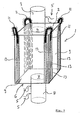
- a bulk material container according to the invention has a container body 1 which can be filled through an opening 4 via a filler neck 3 arranged on its upper side 2 ( Fig.1 ). Loops 5 are used to seal the Einglall gans 3. On the bottom 6 of the container body 1 is also an opening 7 is provided, through which the bulk material by a turn closed by loops 5 Outlet supports 8 can be emptied from the container body.
- the inventive bulk material container in its inventive design further line elements 13 which are arranged approximately parallel to the longitudinal extent of the attached to the container body 1 and the discharge means 14 having carrying loops 11 in an area whose width transverse to the longitudinal extent of the support loop 11 maximum Two and a half times, preferably at most twice, the width of the support loop 11 corresponds.
- the particularly kink-prone corner regions of the bulk goods container are provided in addition to its coating with line elements, which ensures unimpeded discharge of the accumulating on the bulk material container charge even in the case of a particular occurring in the heavily stressed areas damage the coating of the bulk material container.
- the further line elements 13, of which some may be located in the carrying loops, as described below, are preferably incorporated into the base fabric in the warp direction.
- the hitherto required effort for incorporating the line elements usually used in the prior art, which were often introduced into the background fabric in special screen forms, is reduced substantially in the bulk material container according to the invention.
- the carrying loops 11 are applied on another side of the container body 1, for example on the outside thereof, as the coating.
- the further line elements 13, which are woven into the base fabric of the container body 1 in the longitudinal direction of the carrying loops are connected by their arrangement, the coating and the conductive elements of a carrying strap 11 with each other, without both of which must be arranged on the same side of the container body. This is advantageous for the surface of the inside of the container body.
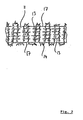
- Fig. 2 11 shows a section of the carrying loop 11 which, in addition to its further line elements 13 incorporated in the warp direction, has a discharge means 14 predominantly incorporated in the weft direction, which is provided with a plurality of strips 16, at least partially protruding from the base fabric, of a dissipative material, preferably a polymer film. is provided.
- the discharge means 14 in the regions of edges 17 of the carrying loop 11 extends into the environment, preferably in the form of a loop, in order to support corona discharges there particularly well.
- the distances between the individual further line elements 13, which are used in the form of electrostatically dissipative yarns or ribbons, amount to between 3 and 20 mm, both in the case of the further line elements 13 assigned to the carrying loops 11, and in the case of the further line elements 13 associated with the container body 1 It is understood that the further line elements 13 of container body 1 and carrying loop 11 are in contact with each other.
- the individual strips 16 of the discharge means 14 are conductively connected to one another in order to further promote the uniform corona discharge.
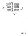
- the discharge means 14 is formed as a polymer film strip, from which the individual strips 16 are cut out ( Fig. 3 ). Since a corona discharge preferably takes place at the narrow edge regions of the discharge means, due to the large edge regions of the polymer film, it is suitable in a wide range for corona discharge. Instead of perpendicular to the longitudinal extent of the Foil-arranged strips are, of course, also conceivable for further cut or striped patterns, in particular those which have a long edge area in comparison to their surface.
- a reinforcing seam 18 is applied to the film, wherein in this case both plastic, metal or other material threads can be used.
- the electrostatically dissipative polymer film strips of the discharge means 14, as well as the discharge means 14, which are alternatively or additionally designed as fine yarn loops, which for example have a thickness Dtex 1100/100, are transversely incorporated and in contact with the longitudinally (warp) woven, as electrostatically dissipative Ribbons or yarn formed further line elements 13.
- the support loops 11 produced in this way are in turn brought into contact both with the coating element formed as a line element and the other line elements 13 which are arranged on the sides 9 of the container body 1. It is likewise conceivable, instead of using the coating, to use conventionally grid-shaped line elements which discharge the bulk material container according to the invention with the polymer film having the discharge strips 16.
- the antistatic coating formed as a line element may consist of a multiplicity of thermoplastics which contain an additive which increases their conductivity.
- an additive which increases their conductivity.
- Such may be, for example, a polymer which is penetrated by an electrically conductive network of microcrystalline needles, which may vary depending on their amount introduced the Ableiten the surface in the specified range. It has been found that such a conductivity-increasing additive is mixed in a mass fraction of 5% to 25% in the preferably consisting of polyolefin plastic material to bring the bleeder in the specified range.
Landscapes
- Engineering & Computer Science (AREA)
- Mechanical Engineering (AREA)
- Textile Engineering (AREA)
- Woven Fabrics (AREA)
- Elimination Of Static Electricity (AREA)
- Packaging Of Annular Or Rod-Shaped Articles, Wearing Apparel, Cassettes, Or The Like (AREA)
- Packages (AREA)
- Bag Frames (AREA)
- Treatment Of Fiber Materials (AREA)
- Control And Other Processes For Unpacking Of Materials (AREA)
- Catching Or Destruction (AREA)
Description
- Die Erfindung betrifft einen flexiblen Schüttgutbehälter in einer Ausbildung nach dem Oberbegriff des Patentanspruches 1.
- Aus der
DE 299 24 464 ist ein Corona-entladungsgeeigneter Schüttgutbehälter der eingangs genannten Art bekannt. Ein solcher Schüttgutbehälter weist im Bereich seiner Tragschlaufen zumindest ein einer Tragschlaufe zugeordnetes Entladungsmittel auf, welches in Form eines exponierten Leiters aus dem Tragschlaufenmaterial herausragt. Trotz der ständig möglichen Corona-Entladungen können sich Teilbereiche des Behälterkörpers temporär aufladen, was zu der Gefahr eines Funkenüberschlags führen kann. Dieses ist einerseits darin begründet, daß die Corona-Entladung in einem gesicherten und in der Nähe des Traggestells befindlichen Bereich in einem verhältnismäßig geringen Umfang stattfindet, andererseits darin, daß die in das Gewebe eingewebten elektrischen Leiter aufgrund ihres vergleichsweise geringen elektrischen Oberflächenableitwiderstandes dennoch Ladungen gut leiten können. - Aus der
EP 1 411 007 A ist ein flexibler Schüttgutbehälter der eingangs genannten Art bekannt, der einen Ableitwiderstand der Oberfläche zwischen 108 und 1012 Ω aufweisen kann. Eingewebte Garne und Fäden mit einem Ableitwiderstand in der Größenordnung von 108 bis 1012 Ω sind in gitterförmigen Rasterformen in das Grundgewebe eingebracht, was dazu führen kann, daß bei mechanischer Beanspruchung keine ungehinderte Ableitung der sich auf dem Schüttgutbehälter ansammelnden Ladung mehr gewährleistet ist. Dies ist insbesondere ein im rauhen Alltagsbetrieb auftauchendes Problem bei Mehrfachverwendung eines derartigen Schüttgutbehälters. - Aus der
US 5,092,683 A ist ebenfalls ein flexibler Schüttgutbehälter bekannt, bei dem ein Ableitwiderstand von 107 Ω bis 109 Ω erreicht werden soll. Dazu sind auch in das Gewebe Garne in gitterförmigen Rasterformen in das Grundgewebe eingebracht, die einen bevorzugten Abstand zwischen 2 und 10 cm aufweisen können. - Diesem flexiblen Schüttgutbehälter haften die gleichen Nachteile an wie im Zusammenhang mit der vorgenannten
EP 1 418 007 A erwähnt. - Es ist Aufgabe der vorliegenden Erfindung, einen flexiblen Schüttgutbehälter der eingangs genannten Art bei elektrostatisch günstigen Ableitwiderständen in der Größenordnung von 108 Ω bis 1011 Ω so zu gestalten, daß dieser in stark beanspruchten Bereichen auch bei Mehrfachverwendung eine Ableitung der sich auf dem Schüttgutbehälter ansammelnden Ladung gewährleistet.
- Zur Lösung dieser Aufgabe zeichnet sich der flexible Schüttgutbehälter der eingangs genannten Art dadurch aus, daß weitere Leitungselemente in etwa parallel zur Längserstreckung der an dem Behälterkörper befestigten und das Entladungsmittel aufweisenden Tragschlaufe in einem Bereich angeodnet sind, dessen Breite quer zur Längserstreckung der Tragschlaufe maximal dem 2,5-fach der Breite der Tragschlaufe entspricht. Der erfindungsgemäße Schüttgutbehälter weist somit eine, vorzugsweise auf der Innenseite des Behälterkörpers aufgebrachte Beschichtung auf, die die Aufgaben der im Stand der Technik verwendeten, in das Gewebematerial eingewebten und häufig rasterförmig angeordneten Leitungsbahnen übernimmt. Da der Ableitwiderstand der Beschichtungsoberfläche zwischen 108 Ω und 1011 Ω liegt, also in einem Bereich der oberhalb der 108 Ω eines üblicherweise bei Schüttgutbehältern verwendeten elektrischen Leiters liegt, findet weiterhin ein Ladungstransport in Richtung der den Tragschlaufen zugeordneten Ladungsmitteln statt. Dieser ist jedoch aufgrund des hohen Ableitwiderstandes nicht geeignet, einen Funkenüberschlag bei lokaler Aufladung zu ermöglichen. Der erfindungsgemäße Behälter weist zur Ableitung seiner elektrostatischen Aufladung die antistatische Beschichtung, das zumindest einer Tragschlaufe zugeordnete Ladungsmittel auf und zusätzlich weitere Leitungselemente, welche als Bändchen oder Fäden ausgebildet sind und ebenfalls aus einem thermoplastischen Kunststoff bestehen, der aufgrund eines seine Leitfähigkeit erhöhenden Zusatzes ebenfalls einen Ableitwiderstand der Oberfläche zwischen 108 und 1011 Ω aufweist. Diese weiteren Leitungselemente befinden sich in Bereichen des Behälterkörpers, die besonders hohen mechanischen Belastungen ausgesetzt sind und ermöglichen somit auch bei einer nach langem Gebrauch möglicherweise beschädigten Beschichtung ein gutes Abfließen der angesammelten elektrostatischen Ladung in Richtung des Entladungsmittels und das dortige Entladen des Schüttgutbehälters mittels Corona-Entladung. Die weiteren Leitungselemente, die sich im Bereich eines Tragschlaufengewebes befinden und sich dort in Kette in Richtung der Längserstreckung der Tragschlaufe erstrecken, verbinden die Entladungsmittel mit dem Leitungsmittel des Behälterkörpers und gewährleisten mithin einen kontinuierlichen Ladungstransport.
- Bei einem weiteren Ausführungsbeispiel der Erfindung ist das Entladungsmittel als dünner Faden ausgebildet und weist vorzugsweise im Bereich der Kanten der Tragschlaufe Fadenschlingen auf, die über die Kanten der Tragschlaufe hinausragen bzw. aus dem Material der Tragschlaufe hervorstehen. Der Faden ist sehr dünn ausgebildet, um ebenfalls eine Corona-Entladung zu ermöglichen und ist in Schußrichtung in das Grundgewebe der Tragschlaufe eingearbeitet. Ein solcher Faden ist vorteilhafterweise über in Kettrichtung eingearbeitete weiteren Leitungselemente, sowie über die erfindungsgemäße Beschichtung mit der Oberfläche des Behälterkörpers in leitendem Kontakt und ist damit maßgeblich an der Entladung des Behälterkörpers beteiligt.
- Bei einer weiteren vorteilhaften Ausbildung der Erfindung weisen zumindest zwei Tragschlaufen Entladungsmittel auf, wobei die Tragschlaufen in leitungsmäßigen Kontakt miteinander stehen, beispielsweise durch Leitungselemente. Diese Leitungselemente, die vorzugsweise in den Eckbereichen des Behälterkörpers verlaufen, unterstützen die gleichmäßige Entladung des Schüttgutbehälters.
- Weitere Vorteile und Einzelheiten der Erfindung ergeben sich aus den nachfolgend beschriebenen schematischen Abbildungen eines erfindungsgemäßen Gegenstandes. In den Abbildungen zeigt:
- Fig. 1
- Eine perspektivische Ansicht eines erfindungsgemäßen Schüttgutbehälters,
- Fig. 2
- eine Draufsicht auf einen Tragschlaufenbereich mit Entladungsmittel und weiteren Leitungselementen,
- Fig. 3
- eine Draufsicht auf einen Teil eines Entladungsmittels.
- Ein erfindungsgemäßer Schüttgutbehälter weist einen Behälterkörper 1 auf, der über einen auf seiner Oberseite 2 angeordneten Einfüllstützen 3 durch eine Öffnung 4 befüllt werden kann (
Fig.1 ). Schlaufen 5 dienen dem Verschluß des Einfüllstützens 3. Auf der Unterseite 6 des Behälterkörpers 1 ist ebenfalls eine Öffnung 7 vorgesehen, über die das Schüttgut durch einen wiederum durch Schlaufen 5 verschließbaren Auslaßstützen 8 aus dem Behälterkörpers entleert werden kann. - In Eckbereichen der Oberseite 2 sind an den Seitenwänden 9 des Behälterkörpers 1 Tragschlaufen 11 angenäht. Alle Tragschlaufen 11 weisen durch dünne Striche 12 kenntlich gemachte Teile eines Entladungsmittels 14 auf.
- Des weiteren weist der erfindungsgemäße Schüttgutbehälter in seiner erfindungsgemäßen Ausbildung weitere Leitungselemente 13 auf, die in etwa parallel zur Längserstreckung der an dem Behälterkörper 1 befestigten und das Entladungsmittel 14 aufweisenden Tragschlaufen 11 in einem Bereich angeordnet sind, dessen Breite quer zur Längserstreckung der Tragschlaufe 11 maximal dem Zweieinhalbfachen, vorzugsweise maximal dem Zweifachen, der Breite der Tragschlaufe 11 entspricht. Hierdurch sind die besonders knickanfälligen Eckbereiche des Schüttgutbehälters zusätzlich zu seiner Beschichtung mit Leitungselementen versehen, die auch im Fall einer insbesondere in den stark beanspruchten Bereichen auftretenden Beschädigung der Beschichtung des Schüttgutbehälters eine ungehinderte Ableitung der sich auf dem Schüttgutbehälter ansammelnden Ladung gewährleistet.
- Die weiteren Leitungselemente 13, von denen sich wie weiter unten beschrieben auch einige in den Tragschlaufen befinden können, sind vorzugsweise in Kettrichtung in das Grundgewebe eingearbeitet. Der bislang benötigte Aufwand zur Einarbeitung der üblicherweise im Stand der Technik verwendeten Leitungselemente, die häufig in besonderen Rasterformen in das Grundgewebe eingebracht wurden, verringert sich bei dem erfindungsgemäßen Schüttgutbehälter wesentlich.
- Bei einer weiteren vorteilhaften Ausgestaltung der Erfindung sind die Tragschlaufen 11 auf einer anderen Seite des Behälterkörpers 1, beispielsweise auf dessen Außenseite, als die Beschichtung aufgebracht. Die weiteren Leitungselemente 13, die in Längsrichtung der Tragschlaufen in das Grundgewebe des Behälterkörpers 1 eingewebt sind, verbinden durch ihre Anordnung die Beschichtung und die leitenden Elemente einer Trageschlaufe 11 miteinander, ohne das beide auf derselben Seite des Behälterkörpers angeordnet sein müssen. Dieses ist vorteilhaft für die Oberfläche der Innenseite des Behälterkörpers 1.
- In der
Fig. 2 ist ein Ausschnitt der Tragschlaufe 11 zu sehen, die zusätzlich zu ihren in Kettrichtung eingearbeiteten weiteren Leitungselementen 13 ein vorwiegend in Schußrichtung eingearbeitetes Entladungsmittel 14 aufweist, welches mit einer Vielzahl von zumindest teilweise aus dem Grundgewebe herausragenden Streifen 16 aus einem ableitfähigen Material, vorzugsweise einer Polymerfolie, versehen ist. Zusätzlich ist das Entladungsmittel 14 in den Bereichen von Kanten 17 der Tragschlaufe 11 in die Umgebung hinauserstreckt, vorzugsweise in Form einer Schlaufe, um dort besonders gut Corona-Entladungen zu unterstützen. Die Abstände zwischen den einzelnen weiteren Leitungselementen 13, die in Form von elektrostatisch ableitfähigen Garnen oder Bändchen verwendet werden, betragen zwischen 3 und 20 mm, sowohl bei den den Tragschlaufen 11 zugeordneten weiteren Leitungselementen 13, als auch bei den dem Behälterkörper 1 zugeordneten weiteren Leitungselementen 13. Es versteht sich, daß die weiteren Leitungselemente 13 von Behälterkörper 1 und Tragschlaufe 11 in Kontakt miteinander stehen. - Ebenso ist es von Vorteil, wenn die einzelnen Streifen 16 des Entladungsmittels 14 leitend miteinander verbunden sind, um die gleichmäßige Corona-Entladung weiter zu fördern.
- Vorteilhafterweise ist das Entladungsmittel 14 als Polymerfolienstreifen ausgebildet, aus dem die einzelnen Streifen 16 ausgeschnitten werden (
Fig. 3 ). Da eine Corona-Entladung vorzugsweise an den schmalen Kantenbereichen des Entladungsmittels stattfindet, ist aufgrund der großen Kantenbereiche der Polymerfolie in weiten Bereichen für eine Corona-Entladung geeignet. Statt senkrecht zur Längserstreckung der Folie angeordneten Streifen sind natürlich auch weitere Schnitt- bzw. Streifenmuster denkbar, insbesondere solche, die einen im Vergleich zu ihrer Oberfläche langen Kantenbereich aufweisen. - Zur Verstärkung der Polymerfolie ist eine Verstärkungsnaht 18 auf die Folie aufgebracht, wobei hierbei sowohl Kunststoff-, Metall- oder andere Materialfäden verwendet werden können. Die elektrostatisch ableitfähigen Polymerfolienstreifen des Entladungsmittels 14 sind ebenso wie die alternativ oder ergänzend als feine Garnschlingen ausgearbeiteten Entladungsmittel 14, welche beispielsweise eine Dicke Dtex 1100/100 aufweisen, in Querrichtung eingearbeitet und stehen in Kontakt mit den in Längsrichtung (Kette) eingewebten, als elektrostatisch ableitfähige Bändchen oder Garn ausgebildeten weiteren Leitungselementen 13. Die in dieser Weise hergestellten Tragschlaufen 11 werden wiederum in Kontakt gebracht sowohl mit dem als Beschichtung ausgebildeten Leitungselement und den weiteren Leitungselementen 13, die auf den Seiten 9 des Behälterkörpers 1 angeordnet sind. Es ist ebenfalls denkbar, statt der Beschichtung herkömmlich rasterförmig angeordnete Leitungselemente zu verwenden, die mit der Entladungsstreifen 16 aufweisenden Polymerfolie den erfindungsgemäßen Schüttgutbehälter entladen.
- Die als Leitungselement ausgebildete antistatische Beschichtung kann aus einer Vielzahl von thermoplastischen Kunststoffen bestehen, welche ein ihre Leitfähigkeit erhöhendes Additiv beinhalten. Ein solches kann beispielsweise ein Polymer sein, welches von einem elektrisch leitfähigen Netzwerk aus mikrokristallinen Nadeln durchdrungen ist, welches je nach ihrer eingebrachten Menge die Ableitfähigkeit der Oberfläche in dem angegebenen Bereich variieren kann. Es hat sich gezeigt, daß ein solcher die Leitfähigkeit erhöhender Zusatz in einem Masseanteil von 5 % bis 25% in die vorzugsweise aus Polyolefin bestehende Kunststoffmasse eingemischt wird, um den Ableitwiderstand in den angegebenen Bereich zu bringen.
Claims (10)
- Flexibler Schüttgutbehälter mit einem Behälterkörper (1), der über zumindest eine Öffnung (4, 7) mit einem Schüttgut befüll- und entleerbar und durch an dem Behälterkörper (1) befestigte Tragschlaufen (11) anhebbar ist, mit einem elektrisch nicht leitenden Grundgewebe und mit zumindest einem zur Leitung von vorzugsweise während eines Befüll- oder Entleervorgangs auftretender elektrostatischer Ladung des Schüttgutbehälters geeigneten Leitungselement, das zur Entladung des Schüttgutbehälters mit wenigstens einem einer Tragschlaufe (11) zugeordneten Entladungsmittel (14) verbunden ist, wobei das als Beschichtung des Behälterkörpers ausgebildete Leitungselement und/oder das Entladungsmittel aus einem thermoplastischen Kunststoff besteht/bestehen, welcher aufgrund eines die Leitfähigkeit erhöhenden Zusatzes einen Ableitwiderstand der Oberfläche zwischen 108 Ω und 1011 Ω aufweist dadurch gekennzeichnet, daß weitere, jeweils der Tragschlaufe (11) und/oder Teilbereichen des Behälterkörpers (1) zugeordnete, als Bändchen oder Fäden ausgebildete Leitungselemente (13) aus einem thermoplastischen Kunststoff vorgesehen sind, die ihrerseits aufgrund eines die Leitfähigkeit erhöhenden Zusatzes einen Ableitwiderstand der Oberfläche zwischen 108 Ω und 1011 Ω aufweisen, wobei die weiteren Leitungselemente (13) in etwa parallel zur Längserstreckung der an dem Behälterkörper (1) befestigten und das Entladungsmittel (14) aufweisenden Tragschlaufe (11) in einem Bereich angeordnet sind, dessen Breite quer zur Längserstreckung der Tragschlaufe (11) maximal dem 2,5-fachen der Breite der Tragschlaufe (11) entspricht, um die Verbindung zwischen dem Leitungselement des Behälterkörpers und dem Entladungsmittel (14) der Tragschlaufe (11) zu gewährleisten.
- Schüttgutbehälter nach Anspruch 1, dadurch gekennzeichnet, daß die weiteren Leitungselemente (13) in Kettrichtung in das Grundgewebe eingearbeitet sind.
- Schüttgutbehälter nach einem der Ansprüche 1 oder 2, dadurch gekennzeichnet, daß die Beschichtung auf einer anderen Seite des Behälterkörpers (1) als die Tragschlaufen (11) aufgebracht ist, wobei die weiteren, dem Behälterkörper (1) zugeordneten Leitungselemente (13) die Beschichtung mit den der Tragschlaufe (11) zugeordneten weiteren Leitungselementen (13) und/oder dem Entladungsmittel (14) verbinden.
- Schüttgutbehälter nach einem der Ansprüche 1 bis 3, dadurch gekennzeichnet, daß das Entladungsmittel (14) als Faden ausgebildet ist und vorzugsweise im Bereich der Kanten (17) der Tragschlaufe (11) Fadenschlingen aufweist.
- Schüttgutbehälter nach einem der Ansprüche 1 bis 4, dadurch gekennzeichnet, daß das Entladungsmittel (14) mit einer Vielzahl von zumindest teilweise aus dem Grundgewebe herausragenden Streifen (16) aus einem ableitfähigen Material versehen ist.
- Schüttgutbehälter nach Anspruch 5, dadurch gekennzeichnet, daß die Streifen (16) leitend miteinander verbunden sind.
- Schüttgutbehälter nach einem der Ansprüche 5 oder 6, dadurch gekennzeichnet, daß die Streifen (16) Teil einer Polymerfolie sind.
- Schüttgutbehälter nach einem der Ansprüche 5 bis 7, dadurch gekennzeichnet, daß das Entladungsmittel (14) eine Nahtverstärkung (18) aufweist.
- Schüttgutbehälter nach einem der Ansprüche 1 bis 8, dadurch gekennzeichnet, daß das Entladungsmittel (14) in Schußrichtung in das Grundgewebe der Tragschlaufe (11) eingearbeitet ist.
- Schüttgutbehälter nach einem der Ansprüche 1 bis 9, mit zumindest zwei Entladungsmittel (14) aufweisenden Tragschlaufen (11), dadurch gekennzeichnet, daß die weiteren Leitungselemente (13) zumindest zweier Tragschlaufen (11) leitungsmäßig miteinander verbunden sind.
Priority Applications (1)
| Application Number | Priority Date | Filing Date | Title |
|---|---|---|---|
| PL05759414T PL1796989T3 (pl) | 2004-09-23 | 2005-07-09 | Zbiornik elastyczny na materiał sypki |
Applications Claiming Priority (2)
| Application Number | Priority Date | Filing Date | Title |
|---|---|---|---|
| DE102004046579A DE102004046579A1 (de) | 2004-09-23 | 2004-09-23 | Flexibler Schüttgutbehälter |
| PCT/EP2005/007460 WO2006032313A1 (de) | 2004-09-23 | 2005-07-09 | Flexibler schüttgutbehälter |
Publications (2)
| Publication Number | Publication Date |
|---|---|
| EP1796989A1 EP1796989A1 (de) | 2007-06-20 |
| EP1796989B1 true EP1796989B1 (de) | 2008-12-10 |
Family
ID=34982108
Family Applications (1)
| Application Number | Title | Priority Date | Filing Date |
|---|---|---|---|
| EP05759414A Expired - Lifetime EP1796989B1 (de) | 2004-09-23 | 2005-07-09 | Flexibler schüttgutbehälter |
Country Status (7)
| Country | Link |
|---|---|
| US (1) | US20080118187A1 (de) |
| EP (1) | EP1796989B1 (de) |
| AT (1) | ATE417005T1 (de) |
| DE (2) | DE102004046579A1 (de) |
| ES (1) | ES2319798T3 (de) |
| PL (1) | PL1796989T3 (de) |
| WO (1) | WO2006032313A1 (de) |
Cited By (1)
| Publication number | Priority date | Publication date | Assignee | Title |
|---|---|---|---|---|
| DE102017007689B3 (de) | 2017-08-16 | 2018-12-20 | Empac GmbH | Flexibler elektrostatisch ableitfähiger Schüttgutbehälter und Verfahren zur Herstellung einer Mehrschichtfolie für einen derartigen Schüttgutbehälter |
Families Citing this family (6)
| Publication number | Priority date | Publication date | Assignee | Title |
|---|---|---|---|---|
| JP2009167538A (ja) * | 2008-01-11 | 2009-07-30 | Toray Ind Inc | 導電性織物の縫合方法およびその方法を用いてなる導電性衣服 |
| US20100122981A1 (en) * | 2008-11-18 | 2010-05-20 | Evironmental Packaging Technologies Limited | Shipping container systems |
| US20110083768A1 (en) * | 2009-10-09 | 2011-04-14 | Environmental Packaging Technologies Limited | Methods, systems, and kits for shipping and/or off-loading granular products |
| CN102811925B (zh) * | 2009-12-02 | 2015-11-25 | 英默里斯滑石美国有限公司 | 具有卸料斜槽的柔性散装存储容器 |
| CN102756867A (zh) * | 2011-04-25 | 2012-10-31 | 宜兴市长风集装袋有限公司 | 防静电型导电集装袋 |
| DE102014010273A1 (de) * | 2014-07-11 | 2016-01-14 | Bayer Technology Services Gmbh | Erdungsfähiger flexibler Schüttgutbehälter |
Family Cites Families (10)
| Publication number | Priority date | Publication date | Assignee | Title |
|---|---|---|---|---|
| DE3938414C2 (de) * | 1989-08-19 | 1994-04-14 | Eurea Verpackung | Schüttgutbehälter aus einem gewebten Tragbeutel und daran befestigten Tragvorrichtungen |
| US5938338A (en) * | 1994-09-09 | 1999-08-17 | Rohm & Haas Company | Recycleable bulk bag containers |
| US6112772A (en) * | 1995-06-01 | 2000-09-05 | Linq Industrial Fabrics, Inc. | Low discharge anti-incendiary flexible intermediate bulk container |
| GB9910000D0 (en) * | 1999-05-01 | 1999-06-30 | Rexam Mulox Ltd | Container bag |
| DE29924464U1 (de) * | 1999-06-30 | 2003-07-31 | NORDENIA Deutschland Emsdetten GmbH, 48282 Emsdetten | Flexibler Schüttgutbehälter |
| DE10048765C2 (de) * | 2000-09-29 | 2003-02-20 | Eurea Verpackung | Antistatisches Gewebe für flexible Schüttgutbehälter |
| CA2426837A1 (en) * | 2000-10-25 | 2002-05-30 | W. Keith Fisher | Anti-static woven fabric and flexible bulk container |
| US7086781B2 (en) * | 2002-06-20 | 2006-08-08 | B.A.G. Corp. | Bulk bag for meat and meat products |
| US6900975B2 (en) * | 2002-07-05 | 2005-05-31 | Sunjit Suni Jut Sanayi Ve Tioaret A.S. | Inner device for neutralization of electrostatic charges from material in contact |
| DE60201032T2 (de) * | 2002-10-16 | 2005-10-13 | Ünsa Ambalaj Sanayi ve Ticaret A.S., Samandira | Flexibler Schüttgutbehälter |
-
2004
- 2004-09-23 DE DE102004046579A patent/DE102004046579A1/de not_active Withdrawn
-
2005
- 2005-07-09 PL PL05759414T patent/PL1796989T3/pl unknown
- 2005-07-09 US US11/575,871 patent/US20080118187A1/en not_active Abandoned
- 2005-07-09 ES ES05759414T patent/ES2319798T3/es not_active Expired - Lifetime
- 2005-07-09 AT AT05759414T patent/ATE417005T1/de not_active IP Right Cessation
- 2005-07-09 EP EP05759414A patent/EP1796989B1/de not_active Expired - Lifetime
- 2005-07-09 DE DE502005006231T patent/DE502005006231D1/de not_active Expired - Fee Related
- 2005-07-09 WO PCT/EP2005/007460 patent/WO2006032313A1/de not_active Ceased
Cited By (2)
| Publication number | Priority date | Publication date | Assignee | Title |
|---|---|---|---|---|
| DE102017007689B3 (de) | 2017-08-16 | 2018-12-20 | Empac GmbH | Flexibler elektrostatisch ableitfähiger Schüttgutbehälter und Verfahren zur Herstellung einer Mehrschichtfolie für einen derartigen Schüttgutbehälter |
| WO2019034273A1 (de) | 2017-08-16 | 2019-02-21 | Empac GmbH | Flexibler elektrostatisch ableitfähiger schüttgutbehälter und verfahren zur herstellung einer mehrschichtfolie für einen derartigen schüttgutbehälter |
Also Published As
| Publication number | Publication date |
|---|---|
| DE102004046579A1 (de) | 2006-04-06 |
| EP1796989A1 (de) | 2007-06-20 |
| DE502005006231D1 (de) | 2009-01-22 |
| PL1796989T3 (pl) | 2009-07-31 |
| ES2319798T3 (es) | 2009-05-12 |
| ATE417005T1 (de) | 2008-12-15 |
| US20080118187A1 (en) | 2008-05-22 |
| WO2006032313A1 (de) | 2006-03-30 |
Similar Documents
| Publication | Publication Date | Title |
|---|---|---|
| DE3938414C2 (de) | Schüttgutbehälter aus einem gewebten Tragbeutel und daran befestigten Tragvorrichtungen | |
| DE60201032T2 (de) | Flexibler Schüttgutbehälter | |
| DE4221380C2 (de) | Flexibler Schüttgutbehälter | |
| DE10048765C2 (de) | Antistatisches Gewebe für flexible Schüttgutbehälter | |
| DE2629409B2 (de) | Kettengewirktes Netz | |
| CH634209A5 (de) | Reissverschluss. | |
| EP1796989A1 (de) | Flexibler schüttgutbehälter | |
| EP0664100A1 (de) | Wischbezug | |
| CH634208A5 (de) | Reissverschluss. | |
| EP0896934B1 (de) | Transportsack aus Gewebe- und/oder Folienmaterial | |
| DE7729501U1 (de) | Sack aus thermoplastischer Kunststoffolie | |
| DE2727441A1 (de) | Container fuer fliess- oder schuettfaehige gueter | |
| DE102018115127B4 (de) | Taschenband für Silosäcke | |
| EP2896728B1 (de) | Filtergewebe | |
| DE19930093A1 (de) | Flexibler Schüttgutbehälter | |
| DE202007012821U1 (de) | Halterung für Silosäcke | |
| DE102018102647A1 (de) | Schutzplane, insbesondere für einen LKW-Aufbau oder für einen Zelt-Aufbau oder für ein Tor | |
| EP1724213B1 (de) | Flexibler Behälter | |
| DE7317863U (de) | Gepacknetz | |
| DE29606123U1 (de) | Schüttgutbehälter aus einem hochfesten Gewebe | |
| DE8913906U1 (de) | Schüttgutbehälter | |
| DE102004034063A1 (de) | Doppelwand aus textilem Material | |
| DE8336862U1 (de) | Schuettgut-Behaelter | |
| DE8914387U1 (de) | Gewebesack aus Kunststoffmaterial | |
| DE8426836U1 (de) | Einlage, vorzugsweise textileinlage, fuer foerderbaender |
Legal Events
| Date | Code | Title | Description |
|---|---|---|---|
| PUAI | Public reference made under article 153(3) epc to a published international application that has entered the european phase |
Free format text: ORIGINAL CODE: 0009012 |
|
| 17P | Request for examination filed |
Effective date: 20070322 |
|
| AK | Designated contracting states |
Kind code of ref document: A1 Designated state(s): AT BE BG CH CY CZ DE DK EE ES FI FR GB GR HU IE IS IT LI LT LU LV MC NL PL PT RO SE SI SK TR |
|
| 17Q | First examination report despatched |
Effective date: 20070720 |
|
| DAX | Request for extension of the european patent (deleted) | ||
| GRAP | Despatch of communication of intention to grant a patent |
Free format text: ORIGINAL CODE: EPIDOSNIGR1 |
|
| GRAS | Grant fee paid |
Free format text: ORIGINAL CODE: EPIDOSNIGR3 |
|
| GRAA | (expected) grant |
Free format text: ORIGINAL CODE: 0009210 |
|
| AK | Designated contracting states |
Kind code of ref document: B1 Designated state(s): AT BE BG CH CY CZ DE DK EE ES FI FR GB GR HU IE IS IT LI LT LU LV MC NL PL PT RO SE SI SK TR |
|
| REG | Reference to a national code |
Ref country code: GB Ref legal event code: FG4D Free format text: NOT ENGLISH |
|
| REG | Reference to a national code |
Ref country code: CH Ref legal event code: EP |
|
| REG | Reference to a national code |
Ref country code: IE Ref legal event code: FG4D Free format text: LANGUAGE OF EP DOCUMENT: GERMAN |
|
| REF | Corresponds to: |
Ref document number: 502005006231 Country of ref document: DE Date of ref document: 20090122 Kind code of ref document: P |
|
| PG25 | Lapsed in a contracting state [announced via postgrant information from national office to epo] |
Ref country code: LT Free format text: LAPSE BECAUSE OF FAILURE TO SUBMIT A TRANSLATION OF THE DESCRIPTION OR TO PAY THE FEE WITHIN THE PRESCRIBED TIME-LIMIT Effective date: 20081210 |
|
| REG | Reference to a national code |
Ref country code: CH Ref legal event code: NV Representative=s name: SCHNEIDER FELDMANN AG PATENT- UND MARKENANWAELTE |
|
| REG | Reference to a national code |
Ref country code: ES Ref legal event code: FG2A Ref document number: 2319798 Country of ref document: ES Kind code of ref document: T3 |
|
| PG25 | Lapsed in a contracting state [announced via postgrant information from national office to epo] |
Ref country code: FI Free format text: LAPSE BECAUSE OF FAILURE TO SUBMIT A TRANSLATION OF THE DESCRIPTION OR TO PAY THE FEE WITHIN THE PRESCRIBED TIME-LIMIT Effective date: 20081210 Ref country code: LV Free format text: LAPSE BECAUSE OF FAILURE TO SUBMIT A TRANSLATION OF THE DESCRIPTION OR TO PAY THE FEE WITHIN THE PRESCRIBED TIME-LIMIT Effective date: 20081210 Ref country code: SI Free format text: LAPSE BECAUSE OF FAILURE TO SUBMIT A TRANSLATION OF THE DESCRIPTION OR TO PAY THE FEE WITHIN THE PRESCRIBED TIME-LIMIT Effective date: 20081210 |
|
| REG | Reference to a national code |
Ref country code: IE Ref legal event code: FD4D |
|
| PG25 | Lapsed in a contracting state [announced via postgrant information from national office to epo] |
Ref country code: RO Free format text: LAPSE BECAUSE OF FAILURE TO SUBMIT A TRANSLATION OF THE DESCRIPTION OR TO PAY THE FEE WITHIN THE PRESCRIBED TIME-LIMIT Effective date: 20081210 Ref country code: EE Free format text: LAPSE BECAUSE OF FAILURE TO SUBMIT A TRANSLATION OF THE DESCRIPTION OR TO PAY THE FEE WITHIN THE PRESCRIBED TIME-LIMIT Effective date: 20081210 Ref country code: IE Free format text: LAPSE BECAUSE OF FAILURE TO SUBMIT A TRANSLATION OF THE DESCRIPTION OR TO PAY THE FEE WITHIN THE PRESCRIBED TIME-LIMIT Effective date: 20081210 Ref country code: BG Free format text: LAPSE BECAUSE OF FAILURE TO SUBMIT A TRANSLATION OF THE DESCRIPTION OR TO PAY THE FEE WITHIN THE PRESCRIBED TIME-LIMIT Effective date: 20090310 |
|
| REG | Reference to a national code |
Ref country code: PL Ref legal event code: T3 |
|
| PG25 | Lapsed in a contracting state [announced via postgrant information from national office to epo] |
Ref country code: SE Free format text: LAPSE BECAUSE OF FAILURE TO SUBMIT A TRANSLATION OF THE DESCRIPTION OR TO PAY THE FEE WITHIN THE PRESCRIBED TIME-LIMIT Effective date: 20090310 Ref country code: PT Free format text: LAPSE BECAUSE OF FAILURE TO SUBMIT A TRANSLATION OF THE DESCRIPTION OR TO PAY THE FEE WITHIN THE PRESCRIBED TIME-LIMIT Effective date: 20090511 Ref country code: CZ Free format text: LAPSE BECAUSE OF FAILURE TO SUBMIT A TRANSLATION OF THE DESCRIPTION OR TO PAY THE FEE WITHIN THE PRESCRIBED TIME-LIMIT Effective date: 20081210 Ref country code: IS Free format text: LAPSE BECAUSE OF FAILURE TO SUBMIT A TRANSLATION OF THE DESCRIPTION OR TO PAY THE FEE WITHIN THE PRESCRIBED TIME-LIMIT Effective date: 20090410 |
|
| PG25 | Lapsed in a contracting state [announced via postgrant information from national office to epo] |
Ref country code: SK Free format text: LAPSE BECAUSE OF FAILURE TO SUBMIT A TRANSLATION OF THE DESCRIPTION OR TO PAY THE FEE WITHIN THE PRESCRIBED TIME-LIMIT Effective date: 20081210 |
|
| PLBE | No opposition filed within time limit |
Free format text: ORIGINAL CODE: 0009261 |
|
| STAA | Information on the status of an ep patent application or granted ep patent |
Free format text: STATUS: NO OPPOSITION FILED WITHIN TIME LIMIT |
|
| PG25 | Lapsed in a contracting state [announced via postgrant information from national office to epo] |
Ref country code: DK Free format text: LAPSE BECAUSE OF FAILURE TO SUBMIT A TRANSLATION OF THE DESCRIPTION OR TO PAY THE FEE WITHIN THE PRESCRIBED TIME-LIMIT Effective date: 20081210 |
|
| 26N | No opposition filed |
Effective date: 20090911 |
|
| PG25 | Lapsed in a contracting state [announced via postgrant information from national office to epo] |
Ref country code: MC Free format text: LAPSE BECAUSE OF NON-PAYMENT OF DUE FEES Effective date: 20090731 |
|
| PG25 | Lapsed in a contracting state [announced via postgrant information from national office to epo] |
Ref country code: DE Free format text: LAPSE BECAUSE OF NON-PAYMENT OF DUE FEES Effective date: 20100202 |
|
| PG25 | Lapsed in a contracting state [announced via postgrant information from national office to epo] |
Ref country code: GR Free format text: LAPSE BECAUSE OF FAILURE TO SUBMIT A TRANSLATION OF THE DESCRIPTION OR TO PAY THE FEE WITHIN THE PRESCRIBED TIME-LIMIT Effective date: 20090311 |
|
| PG25 | Lapsed in a contracting state [announced via postgrant information from national office to epo] |
Ref country code: AT Free format text: LAPSE BECAUSE OF NON-PAYMENT OF DUE FEES Effective date: 20090709 |
|
| PG25 | Lapsed in a contracting state [announced via postgrant information from national office to epo] |
Ref country code: LU Free format text: LAPSE BECAUSE OF NON-PAYMENT OF DUE FEES Effective date: 20090709 |
|
| PG25 | Lapsed in a contracting state [announced via postgrant information from national office to epo] |
Ref country code: HU Free format text: LAPSE BECAUSE OF FAILURE TO SUBMIT A TRANSLATION OF THE DESCRIPTION OR TO PAY THE FEE WITHIN THE PRESCRIBED TIME-LIMIT Effective date: 20090611 |
|
| PG25 | Lapsed in a contracting state [announced via postgrant information from national office to epo] |
Ref country code: TR Free format text: LAPSE BECAUSE OF FAILURE TO SUBMIT A TRANSLATION OF THE DESCRIPTION OR TO PAY THE FEE WITHIN THE PRESCRIBED TIME-LIMIT Effective date: 20081210 |
|
| PG25 | Lapsed in a contracting state [announced via postgrant information from national office to epo] |
Ref country code: CY Free format text: LAPSE BECAUSE OF FAILURE TO SUBMIT A TRANSLATION OF THE DESCRIPTION OR TO PAY THE FEE WITHIN THE PRESCRIBED TIME-LIMIT Effective date: 20081210 |
|
| REG | Reference to a national code |
Ref country code: FR Ref legal event code: TP Owner name: EMPAC GMBH, DE Effective date: 20121211 |
|
| REG | Reference to a national code |
Ref country code: CH Ref legal event code: PUE Owner name: EMPAC GMBH, DE Free format text: FORMER OWNER: NORDENIA DEUTSCHLAND EMSDETTEN GMBH, DE |
|
| REG | Reference to a national code |
Ref country code: NL Ref legal event code: TD Effective date: 20130418 |
|
| REG | Reference to a national code |
Ref country code: GB Ref legal event code: 732E Free format text: REGISTERED BETWEEN 20130418 AND 20130424 |
|
| REG | Reference to a national code |
Ref country code: ES Ref legal event code: PC2A Owner name: EMPAC GMBH Effective date: 20130509 |
|
| REG | Reference to a national code |
Ref country code: NL Ref legal event code: SD Effective date: 20130808 |
|
| BECA | Be: change of holder's address |
Owner name: EMPAC G.M.B.H.HOLLEFELDSTRASSE 34,D-48282 EMSDETTE Effective date: 20130905 |
|
| BECH | Be: change of holder |
Owner name: EMPAC G.M.B.H. Effective date: 20130905 |
|
| REG | Reference to a national code |
Ref country code: FR Ref legal event code: PLFP Year of fee payment: 12 |
|
| REG | Reference to a national code |
Ref country code: FR Ref legal event code: PLFP Year of fee payment: 13 |
|
| PGFP | Annual fee paid to national office [announced via postgrant information from national office to epo] |
Ref country code: PL Payment date: 20170608 Year of fee payment: 13 |
|
| PGFP | Annual fee paid to national office [announced via postgrant information from national office to epo] |
Ref country code: NL Payment date: 20170731 Year of fee payment: 13 |
|
| PGFP | Annual fee paid to national office [announced via postgrant information from national office to epo] |
Ref country code: ES Payment date: 20170803 Year of fee payment: 13 Ref country code: IT Payment date: 20170710 Year of fee payment: 13 Ref country code: FR Payment date: 20170724 Year of fee payment: 13 Ref country code: GB Payment date: 20170706 Year of fee payment: 13 |
|
| PGFP | Annual fee paid to national office [announced via postgrant information from national office to epo] |
Ref country code: BE Payment date: 20170728 Year of fee payment: 13 |
|
| PGFP | Annual fee paid to national office [announced via postgrant information from national office to epo] |
Ref country code: CH Payment date: 20171030 Year of fee payment: 13 |
|
| REG | Reference to a national code |
Ref country code: CH Ref legal event code: PL |
|
| REG | Reference to a national code |
Ref country code: NL Ref legal event code: MM Effective date: 20180801 |
|
| GBPC | Gb: european patent ceased through non-payment of renewal fee |
Effective date: 20180709 |
|
| REG | Reference to a national code |
Ref country code: BE Ref legal event code: MM Effective date: 20180731 |
|
| PG25 | Lapsed in a contracting state [announced via postgrant information from national office to epo] |
Ref country code: CH Free format text: LAPSE BECAUSE OF NON-PAYMENT OF DUE FEES Effective date: 20180731 Ref country code: FR Free format text: LAPSE BECAUSE OF NON-PAYMENT OF DUE FEES Effective date: 20180731 Ref country code: LI Free format text: LAPSE BECAUSE OF NON-PAYMENT OF DUE FEES Effective date: 20180731 Ref country code: GB Free format text: LAPSE BECAUSE OF NON-PAYMENT OF DUE FEES Effective date: 20180709 |
|
| PG25 | Lapsed in a contracting state [announced via postgrant information from national office to epo] |
Ref country code: BE Free format text: LAPSE BECAUSE OF NON-PAYMENT OF DUE FEES Effective date: 20180731 Ref country code: NL Free format text: LAPSE BECAUSE OF NON-PAYMENT OF DUE FEES Effective date: 20180801 |
|
| PG25 | Lapsed in a contracting state [announced via postgrant information from national office to epo] |
Ref country code: IT Free format text: LAPSE BECAUSE OF NON-PAYMENT OF DUE FEES Effective date: 20180709 |
|
| REG | Reference to a national code |
Ref country code: ES Ref legal event code: FD2A Effective date: 20190917 |
|
| PG25 | Lapsed in a contracting state [announced via postgrant information from national office to epo] |
Ref country code: ES Free format text: LAPSE BECAUSE OF NON-PAYMENT OF DUE FEES Effective date: 20180710 |
|
| PG25 | Lapsed in a contracting state [announced via postgrant information from national office to epo] |
Ref country code: PL Free format text: LAPSE BECAUSE OF NON-PAYMENT OF DUE FEES Effective date: 20180709 |