EP1796123B1 - Ecran plasma - Google Patents
Ecran plasma Download PDFInfo
- Publication number
- EP1796123B1 EP1796123B1 EP06025724A EP06025724A EP1796123B1 EP 1796123 B1 EP1796123 B1 EP 1796123B1 EP 06025724 A EP06025724 A EP 06025724A EP 06025724 A EP06025724 A EP 06025724A EP 1796123 B1 EP1796123 B1 EP 1796123B1
- Authority
- EP
- European Patent Office
- Prior art keywords
- barrier rib
- discharge cell
- electrode
- width
- plasma display
- Prior art date
- Legal status (The legal status is an assumption and is not a legal conclusion. Google has not performed a legal analysis and makes no representation as to the accuracy of the status listed.)
- Not-in-force
Links
- 230000004888 barrier function Effects 0.000 claims description 101
- 239000000758 substrate Substances 0.000 claims description 28
- 229910052751 metal Inorganic materials 0.000 claims description 3
- 239000002184 metal Substances 0.000 claims description 3
- 230000003340 mental effect Effects 0.000 claims 1
- 239000011295 pitch Substances 0.000 description 13
- 230000003247 decreasing effect Effects 0.000 description 5
- 230000001419 dependent effect Effects 0.000 description 5
- 238000010276 construction Methods 0.000 description 3
- XLOMVQKBTHCTTD-UHFFFAOYSA-N Zinc monoxide Chemical compound [Zn]=O XLOMVQKBTHCTTD-UHFFFAOYSA-N 0.000 description 2
- 230000007423 decrease Effects 0.000 description 2
- 230000000694 effects Effects 0.000 description 2
- 238000010304 firing Methods 0.000 description 2
- 239000007789 gas Substances 0.000 description 2
- 238000000638 solvent extraction Methods 0.000 description 2
- 230000015556 catabolic process Effects 0.000 description 1
- 238000011161 development Methods 0.000 description 1
- 230000018109 developmental process Effects 0.000 description 1
- AMGQUBHHOARCQH-UHFFFAOYSA-N indium;oxotin Chemical compound [In].[Sn]=O AMGQUBHHOARCQH-UHFFFAOYSA-N 0.000 description 1
- 239000011261 inert gas Substances 0.000 description 1
- 238000004519 manufacturing process Methods 0.000 description 1
- 239000011159 matrix material Substances 0.000 description 1
- 238000000034 method Methods 0.000 description 1
- 230000002459 sustained effect Effects 0.000 description 1
- XOLBLPGZBRYERU-UHFFFAOYSA-N tin dioxide Chemical compound O=[Sn]=O XOLBLPGZBRYERU-UHFFFAOYSA-N 0.000 description 1
- 229910001887 tin oxide Inorganic materials 0.000 description 1
- 239000011787 zinc oxide Substances 0.000 description 1
Images


Classifications
-
- H—ELECTRICITY
- H01—ELECTRIC ELEMENTS
- H01J—ELECTRIC DISCHARGE TUBES OR DISCHARGE LAMPS
- H01J11/00—Gas-filled discharge tubes with alternating current induction of the discharge, e.g. alternating current plasma display panels [AC-PDP]; Gas-filled discharge tubes without any main electrode inside the vessel; Gas-filled discharge tubes with at least one main electrode outside the vessel
- H01J11/20—Constructional details
- H01J11/34—Vessels, containers or parts thereof, e.g. substrates
- H01J11/36—Spacers, barriers, ribs, partitions or the like
-
- H—ELECTRICITY
- H01—ELECTRIC ELEMENTS
- H01J—ELECTRIC DISCHARGE TUBES OR DISCHARGE LAMPS
- H01J11/00—Gas-filled discharge tubes with alternating current induction of the discharge, e.g. alternating current plasma display panels [AC-PDP]; Gas-filled discharge tubes without any main electrode inside the vessel; Gas-filled discharge tubes with at least one main electrode outside the vessel
- H01J11/20—Constructional details
- H01J11/22—Electrodes, e.g. special shape, material or configuration
- H01J11/24—Sustain electrodes or scan electrodes
-
- H—ELECTRICITY
- H01—ELECTRIC ELEMENTS
- H01J—ELECTRIC DISCHARGE TUBES OR DISCHARGE LAMPS
- H01J11/00—Gas-filled discharge tubes with alternating current induction of the discharge, e.g. alternating current plasma display panels [AC-PDP]; Gas-filled discharge tubes without any main electrode inside the vessel; Gas-filled discharge tubes with at least one main electrode outside the vessel
- H01J11/20—Constructional details
- H01J11/22—Electrodes, e.g. special shape, material or configuration
- H01J11/32—Disposition of the electrodes
-
- H—ELECTRICITY
- H01—ELECTRIC ELEMENTS
- H01J—ELECTRIC DISCHARGE TUBES OR DISCHARGE LAMPS
- H01J2211/00—Plasma display panels with alternate current induction of the discharge, e.g. AC-PDPs
- H01J2211/20—Constructional details
- H01J2211/22—Electrodes
- H01J2211/24—Sustain electrodes or scan electrodes
- H01J2211/245—Shape, e.g. cross section or pattern
-
- H—ELECTRICITY
- H01—ELECTRIC ELEMENTS
- H01J—ELECTRIC DISCHARGE TUBES OR DISCHARGE LAMPS
- H01J2211/00—Plasma display panels with alternate current induction of the discharge, e.g. AC-PDPs
- H01J2211/20—Constructional details
- H01J2211/22—Electrodes
- H01J2211/32—Disposition of the electrodes
- H01J2211/323—Mutual disposition of electrodes
-
- H—ELECTRICITY
- H01—ELECTRIC ELEMENTS
- H01J—ELECTRIC DISCHARGE TUBES OR DISCHARGE LAMPS
- H01J2211/00—Plasma display panels with alternate current induction of the discharge, e.g. AC-PDPs
- H01J2211/20—Constructional details
- H01J2211/34—Vessels, containers or parts thereof, e.g. substrates
- H01J2211/36—Spacers, barriers, ribs, partitions or the like
- H01J2211/361—Spacers, barriers, ribs, partitions or the like characterized by the shape
- H01J2211/363—Cross section of the spacers
Definitions
- the present invention relates to a plasma display device and, more particularly, to a discharge cell capable of increasing luminance while decreasing jitter, and a barrier rib structure provided in the discharge cell.
- a plasma display panel is an image display device in which discharge cells are formed between a rear substrate having barrier ribs formed thereon and a front substrate opposite to the rear substrate.
- the plasma display panel implements an image by exciting phosphors with Vacuum UltraViolet (VUV) rays generated when an inert gas within each discharge cell is discharged by a high frequency voltage.
- VUV Vacuum UltraViolet
- the plasma display panel is adapted to implement an image by employing red (R), green (G) and blue (B) visible rays, which are generated when VUV radiated from plasma obtained through a gas discharge excites phosphors.
- the plasma display device is adapted to implement an image as a surface discharge or an opposite discharge is generated from the inside of a discharge cell by means of driving voltages applied to scan electrodes, sustain electrodes and address electrodes.
- a long gap arrangement method in which scan electrodes Y and sustain electrodes Z are spaced apart from each other at a predetermined distance so as to secure the aperture ratio is employed.
- the barrier ribs having a bottom width wider than a top width close the four sides, making it difficult to sufficiently secure discharge space.
- EP 1 187 166 A2 may be construed to disclose a plasma display panel (PDP) according to the preamble of claim 1.
- the PDP may comprise a discharge cell including display electrodes formed on a front substrate structure, and an address electrode formed on a back substrate structure, the discharge cell being separated from neighboring discharge cells by means of a vertical wall and a horizontal wall crossing the vertical wall on the back substrate, wherein the vertical wall has a bottom width wider than a top width, wherein a difference between the bottom width and the top width of the first barrier rib is approximately 70 ⁇ m, and wherein the second barrier rib has a bottom width wider than a top width.
- A) may be construed to disclose a PDP comprising a discharge space including display electrodes formed on a front substrate, and an address electrode formed on a rear substrate, the discharge space being separated from neighboring discharge cells by means of a first barrier rib on the rear substrate, wherein the first barrier rib has a bottom width wider than a top width and a difference between the bottom width and the top width of the first barrier rib is approximately 40 ⁇ m.
- a PDP comprising a dielectric layer including electrodes formed on a front substrate, and an address electrode formed on a rear substrate, the discharge cell being separated from neighboring discharge cells by means of a first barrier rib on the rear substrate, wherein the first barrier rib has a bottom width wider than a top width and the distance between the scan electrode and the sustain electrode is set in the range of 50 to 200 ⁇ m.
- US 2005/0168413 A1 may be construed to disclose a PDP.
- the PDP may comprise a discharge cell including a scan electrode and a sustain electrode formed on a front substrate, and an address electrode formed on a rear substrate, the discharge cell being separated from neighboring discharge cells by means of a first barrier rib, wherein a distance between the scan electrode and the sustain electrode is set in the range of 10 to 100 ⁇ m, and wherein the first barrier rib has a bottom width wider than a top width.
- the present invention is to solve at least the problems and disadvantages of the background art.
- a plasma display device according to claim 1 is provided.
- the second barrier rib fulfills a condition of 0 ⁇ the bottom width - the top width ⁇ 50 ⁇ m (see also claim 1) or/and 1 ⁇ the bottom width / the top width ⁇ 1.8 (see dependent claim 6).
- the range of 0.15 ⁇ the valid overlap area / a discharge cell area ⁇ 1 is fulfilled (see dependent claim 7). Furthermore, the valid overlap area is 0.63 ⁇ the width of the valid overlap area / the first pitch of the discharge cell ⁇ 1 (see dependent claim 8), and 0.24 ⁇ the length of the valid overlap area / the second pitch of the discharge cell ⁇ 1 (see dependent claim 9).
- the present invention relates to a plasma display device, and a discharge cell structure, which can decrease jitter and lower discharge voltages while improving luminance.
- the present invention presents a variety of barrier rib structures in a discharge cell having scan electrodes and sustain electrodes arranged in a long gap form, and also a distance range of the scan electrodes and the sustain electrodes in a discharge cell having a close type barrier rib structure.
- FIG. 1 is a view illustrating the construction of a panel P according to an embodiment of the present invention.
- the panel P includes a front substrate A and a rear substrate B coalesced together with a gap therebetween.
- Scan electrodes 1 and sustain electrodes 2 are formed on the front substrate A.
- Address electrodes 6 are formed on the rear substrate B.
- the scan electrodes 1 and the sustain electrodes 2 cross the address electrodes 6 within cells.
- Each of the scan electrodes 1 includes a transparent electrode 1b and a bus electrode 1a.
- Each of the sustain electrodes 2 includes a transparent electrode 2b and a bus electrode 2a.
- the transparent electrodes are formed from tin oxide and zinc oxide called Indium Tin Oxide (ITO), and generate a plasma discharge and cause light, generated within the cells, to be discharged to the outside.
- ITO Indium Tin Oxide
- the bus electrodes 1a and 2a which are overlapped with the transparent electrodes within a range of 0.4 to 0.5 times a width of the transparent electrode is provided.
- a dielectric layer 3 is formed on the scan electrodes 1 and the sustain electrodes 2.
- a protection layer 4 for protecting the dielectric layer 3 may also be formed on the dielectric layer 3.
- a dielectric layer 8 is also formed on the address electrodes 6.
- Barrier ribs 7 partitioning the discharge cells in the first/the second directions, and R, G and B phosphors 9 coated on the dielectric layer 8 and the barrier ribs 7 are formed on the dielectric layer 8.
- the construction of the plasma display panel according to an embodiment of the present invention is not limited to the construction of FIG. 1 .
- the scan electrode 1 and the sustain electrode 2 can have an ITO-less structure including only the bus electrodes 1a and 2a without the transparent electrodes 1b and 2b made of ITO.
- the scan electrode 1 and the sustain electrode 2 can have an integral type Black Matrix (BM) structure in which a BM is integrally formed in the front substrate A, though not shown in the drawing.
- BM Black Matrix
- the scan electrode 1 and the sustain electrode 2 may include two or more electrode lines, and may also include other electrodes.
- the plasma display panel is driven with one frame being divided into several subfields having a different number of emissions in order to implement gray levels of an image.
- Each subfield is divided into a reset period in which the whole screen is reset, an address period in which a scan line is selected and a cell is selected from a selected scan line, and a sustain period in which gray levels are implemented according to a discharge number.
- a driving waveform applied during a first subfield is described below with reference to FIG. 2 .
- the driving waveform is divided into a reset period RP1, an address period AP and a sustain period SP.
- the reset period comprises a setup period SU1 in which a voltage level of the scan electrode rises, and a setdown period SD1 in which a voltage level of the scan electrode falls.
- a setup signal PR1 that gradually rises up to a reset voltage Vr1 is applied to the entire scan electrodes Y. Further, in this period, wall charges are slowly accumulated within the cells while a setup discharge is generated by the setup signal PR1.
- a setdown signal NR that gradually falls to a negative voltage -Ve is applied to the scan electrode, so that excessive wall charges unnecessary for an address discharge are erased from the discharge cells.
- a positive voltage is applied to the sustain electrode Z in synchronization with the setdown signal.
- a scan pulse -SCNP falling from a scan bias voltage Vyb to a negative scan voltage -Vy is sequentially applied to the scan electrode Y, and at the same time, a positive data pulse DP is applied to the address electrode X.
- a positive bias voltage is sustained to the sustain electrode Z. Accordingly, during the address period AP, the address discharge is generated due to a voltage difference between the scan pulse -SCNP and the data pulse DP, so that a discharge cell is selected.
- a sustain pulse SUSP having a positive sustain voltage Vs is alternately applied to the scan electrode Y and the sustain electrode Z, so that a sustain discharge is generated and light is displayed.
- Vs positive sustain voltage
- the amount of light emitted is increased as the number of the sustain pulse SUSP supplied during the sustain period SP increases. Accordingly, luminance can be improved.
- the present invention can be applied to a discharge cell including electrodes arranged in a long gap structure, and a plasma display device equipped with the discharge cell.
- the long gap refers to one of a distance the transparent electrodes ITO constituting the scan electrode Y and the sustain electrode Z, and a distance between the metal electrodes, which is a smaller one. It is meant that the distance is 90 ⁇ m. Further, when the distance is 500 ⁇ m, it can be used for display devices.
- the long gap according to an embodiment of the present invention can be set in the range of 90 to 200 ⁇ m
- a discharge cell equipped with the electrodes of the long gap structure illustrated in FIG. 3 is partitioned by close type barrier ribs, and it includes the first barrier ribs 44, and the second barrier ribs 45 crossing the first barrier ribs 44.
- a top width and a bottom width of the first barrier rib 44 and the second barrier rib 45 are designed so that a slashed valid overlap area Ls and a valid discharge space are expanded.
- a valid overlap area according to an embodiment of the present invention is a region overlapped with the scan electrode Y and the rear substrate exposed within the discharge space without being overlapped with the first barrier ribs 44 and the second barrier ribs 45. More particularly, the valid overlap area refers to the remaining regions of the rear substrate other than regions in which the first barrier ribs and the second barrier ribs are formed, and a region overlapped with the scan electrode Y.
- top/bottom widths of a barrier rib which fulfills conditions, is described below with reference to FIG. 4 .
- the discharge cell is a discharge cell constituting a 42-inch XGA-grade panel. It can be varied depending on a panel size or a resolution level.
- the first barrier rib has the top width 44h of 180 ⁇ m and the bottom width 441 of 260 ⁇ m
- the second barrier rib has the top width 45h of 60 ⁇ m and the bottom width 451 of 110 ⁇ m.
- the width Lh of the slashed valid overlap area is 190 ⁇ m and the length Lv of the slashed valid overlap area is 165 ⁇ m.
- the area (overlap area 1) of the valid overlap area becomes 190 ⁇ m x 165 ⁇ m.
- the first barrier rib has the top width 44h of 180 ⁇ m and the bottom width 441 of 240 ⁇ m
- the second barrier rib has the top width 45h of 60 ⁇ m and the bottom width 451 of 90 ⁇ m.
- the width Lh of the slashed valid overlap area is 210 ⁇ m and the length Lv of the slashed valid overlap area is 175 ⁇ m.
- the area (overlap area 2) of the valid overlap area becomes 210 ⁇ m x 175 ⁇ m.
- the discharge cell illustrated in FIG. 4 has the first pitch Ph of 300 ⁇ m.
- the discharge cell may have a different the first pitch depending on a panel size, a picture level, a manufacturing model and/or the like. Further, discharge cells constituting the same panel may have different pitches depending on R, G and B color temperatures.
- a width ratio and a pitch ratio in the top widths 44h and 45h, the bottom widths 441 and 451, and the area Ls of the valid overlap area of the barrier ribs, and the area of the valid overlap area may be varied in at least one discharge cell that emits a different color of light.
- At least one of the top widths 44h and 45h, the bottom widths 441 and 451, the pitches Ph and Pv, and the valid overlap area Ls of the first and the second barrier ribs can be the greatest in the B discharge cell, and is greater in the G discharge cell than in the R discharge cell or the same both in the G discharge cell and the R discharge cell.
- the area of the valid overlap area is in general 150 ⁇ m x 70 ⁇ m.
- the plasma display panel according to an embodiment of the present invention can reduce jitter and discharge voltages, and can enhance luminance.
- FIG. 6 An effect in which a discharge voltage is lowered can also be confirmed through FIG. 6 . From FIG. 6 , it can be seen that in the case where the barrier ribs having the values of the top/bottom widths shown in FIG. 4 are formed, a discharge voltage drops from 196 to 188 and luminance rises from 192 to 205, compared with a conventional panel.
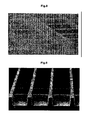
- the barrier ribs can include a channel type barrier rib in which grooves are formed in the first barrier ribs or the second barrier ribs, as illustrated in FIGS. 7 and 8 , and a differential type barrier rib in which the height of barrier ribs in a second direction are lower than that of barrier ribs in a first direction in order to secure a gas exhaust path, as illustrated in FIG. 9 .
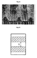
- a discharge cell can have barrier ribs of a close type so that it is partitioned by a beehive shape as illustrated in FIG. 10 .
- a discharge cell can have projections formed on the second barrier rib at a predetermined distance, and can have a fishbone shape in which between-the projections becomes exhaust paths between neighboring discharge cells.
- the scan electrode or the sustain electrode of the present invention can have a stripe structure and can be opposite to each other while forming a long gap, as in a first embodiment of FIG. 13 , but can have a patterned blank structure in which a portion of the region of the transparent electrode is removed in order to secure the aperture ratio in the stripe form, as illustrated in FIG. 14 .
- projections can be projected toward a discharge space in a stripe form, as illustrated in FIG. 15
- the projections of the electrode can be patterned in a T shape, as illustrated in FIG. 16 .
- the scan electrode or the sustain electrode can have a patterned structure in which an internal region of the projections of the electrode is removed in order to secure the aperture ratio, as illustrated in FIG. 17 .
- barrier ribs and embodiments of the electrodes are not limited to the illustrated drawings, and the effects of the present invention can be accomplished if the scan electrode and the sustain electrode form the long gap, and the top and bottom widths of the barrier ribs fulfill the numerical range presented by the present invention in order to secure the valid overlap area.
Landscapes
- Engineering & Computer Science (AREA)
- Physics & Mathematics (AREA)
- Plasma & Fusion (AREA)
- Chemical & Material Sciences (AREA)
- Materials Engineering (AREA)
- Gas-Filled Discharge Tubes (AREA)
Claims (9)
- Dispositif d'affichage à plasma (P) comprenant une cellule de décharge incluant une électrode de balayage (1, Y) et une électrode de maintien (2, Z) formées sur un substrat avant (A), et une électrode d'adresse (6, X) formée sur un substrat arrière (B), la cellule de décharge étant séparée de cellules de décharge voisines au moyen d'une première nervure barrière (44) et d'une deuxième nervure barrière (45) coupant la première nervure barrière sur le substrat arrière,
dans lequel la première nervure barrière a une largeur inférieure (441) plus large qu'une largeur supérieure (44h),
dans lequel une différence entre la largeur inférieure et la largeur supérieure de la première nervure barrière est fixée dans la plage de 80 µm ou moins, et
dans lequel la deuxième nervure barrière a une largeur inférieure (451) plus large qu'une largeur supérieure (45h),
caractérisé en ce que
une valeur obtenue en divisant une superficie de chevauchement (Ls) de l'électrode de balayage et une superficie du substrat arrière autre qu'une région dans laquelle les nervures barrière sont formées au sein de la cellule de décharge par une superficie de la cellule de décharge est supérieure à 0,15 ; et
une différence entre la largeur inférieure et la largeur supérieure de la deuxième nervure barrière est fixée dans la plage de 50 µm ou moins. - Dispositif d'affichage à plasma selon la revendication 1, dans lequel une valeur, dans laquelle la largeur inférieure de la première nervure barrière est divisée par la largeur supérieure de la première nervure barrière, est supérieure à 1 et inférieure à 1,4.
- Dispositif d'affichage à plasma selon la revendication 1, dans lequel la cellule de décharge est partitionnée par une d'une nervure barrière de type fermé dans laquelle quatre directions sont partitionnées par la première nervure barrière, d'une nervure barrière de type canal dans laquelle des rainures sont formées dans la première nervure barrière ou la deuxième nervure barrière, et d'une nervure barrière de type différentiel dans laquelle une hauteur de la première nervure barrière est différente de celle de la deuxième nervure barrière.
- Dispositif d'affichage à plasma selon la revendication 1, dans lequel :l'électrode de balayage et l'électrode de maintien comprennent une électrode transparente et une électrode métallique partiellement chevauchée par l'électrode transparente, etla distance entre l'électrode de balayage et l'électrode de maintien est la distance la plus courte entre une distance entre les électrodes transparentes et une distance entre les électrodes métalliques.
- Dispositif d'affichage à plasma selon la revendication 4, dans lequel une largeur de l'électrode métallique chevauchée par l'électrode transparente est dans la plage de 0,4 à 0,5 fois une largeur de l'électrode transparente.
- Dispositif d'affichage à plasma selon la revendication 1, dans lequel :une valeur, dans laquelle la largeur inférieure de la deuxième nervure barrière est divisée par la largeur supérieure de la deuxième nervure barrière, est supérieure à 1 et inférieure à 1,8.
- Dispositif d'affichage à plasma selon la revendication 1, dans lequel la valeur obtenue en divisant la superficie de chevauchement (Ls) par la superficie de la cellule de décharge est supérieure à 0,15 et inférieure à 1.
- Dispositif d'affichage à plasma selon la revendication 1, dans lequel la valeur obtenue en divisant une longueur horizontale (Lh) d'une superficie de chevauchement de l'électrode de balayage et une superficie du substrat arrière autre qu'une région dans laquelle les nervures barrière sont formées au sein de la cellule de décharge par un pas horizontal (Ph) de la cellule de décharge est supérieure à 0,63 et inférieure à 1.
- Dispositif d'affichage à plasma selon la revendication 1, dans lequel la valeur obtenue en divisant une longueur verticale (Lv) d'une superficie de chevauchement pour l'électrode de balayage et une superficie du substrat arrière autre qu'une région dans laquelle les nervures barrière sont formées au sein de la cellule de décharge par un pas vertical (Pv) de la cellule de décharge est supérieure à 0,24 et inférieure à 1.
Applications Claiming Priority (1)
| Application Number | Priority Date | Filing Date | Title |
|---|---|---|---|
| KR1020050121823A KR100755306B1 (ko) | 2005-12-12 | 2005-12-12 | 플라즈마 디스플레이 패널 |
Publications (3)
| Publication Number | Publication Date |
|---|---|
| EP1796123A2 EP1796123A2 (fr) | 2007-06-13 |
| EP1796123A3 EP1796123A3 (fr) | 2009-12-23 |
| EP1796123B1 true EP1796123B1 (fr) | 2011-08-24 |
Family
ID=37896089
Family Applications (1)
| Application Number | Title | Priority Date | Filing Date |
|---|---|---|---|
| EP06025724A Not-in-force EP1796123B1 (fr) | 2005-12-12 | 2006-12-12 | Ecran plasma |
Country Status (5)
| Country | Link |
|---|---|
| US (1) | US7750567B2 (fr) |
| EP (1) | EP1796123B1 (fr) |
| JP (1) | JP2007165315A (fr) |
| KR (1) | KR100755306B1 (fr) |
| CN (1) | CN1983498B (fr) |
Families Citing this family (2)
| Publication number | Priority date | Publication date | Assignee | Title |
|---|---|---|---|---|
| KR100879470B1 (ko) * | 2007-03-19 | 2009-01-20 | 삼성에스디아이 주식회사 | 플라즈마 디스플레이 패널 |
| CN114783310B (zh) * | 2022-04-18 | 2024-04-09 | 武汉精立电子技术有限公司 | 一种用于立方体三色合光棱镜与微显示屏贴合的贴合机构、方法和系统 |
Citations (2)
| Publication number | Priority date | Publication date | Assignee | Title |
|---|---|---|---|---|
| EP1187166A2 (fr) * | 2000-09-06 | 2002-03-13 | Fujitsu Hitachi Plasma Display Limited | Panneau d'affichage à plasma et son procédé de fabrication |
| US20050168413A1 (en) * | 2001-08-24 | 2005-08-04 | Sony Corporation | Plasma display apparatus and driving method thereof |
Family Cites Families (27)
| Publication number | Priority date | Publication date | Assignee | Title |
|---|---|---|---|---|
| US6787995B1 (en) * | 1992-01-28 | 2004-09-07 | Fujitsu Limited | Full color surface discharge type plasma display device |
| JPH05242811A (ja) * | 1992-02-04 | 1993-09-21 | Nec Corp | プラズマディスプレイパネル |
| JPH0721923A (ja) * | 1993-07-07 | 1995-01-24 | Nec Corp | プラズマディスプレイパネル |
| US6023130A (en) * | 1995-09-06 | 2000-02-08 | Kyocera Corporation | Plasma display substrate and a production method thereof |
| JPH09330663A (ja) * | 1996-06-07 | 1997-12-22 | Nec Corp | 面放電形acプラズマディスプレイパネル |
| JPH10188825A (ja) * | 1996-10-30 | 1998-07-21 | Toray Ind Inc | プラズマディスプレイパネル |
| JP3705914B2 (ja) * | 1998-01-27 | 2005-10-12 | 三菱電機株式会社 | 面放電型プラズマディスプレイパネル及びその製造方法 |
| JP3864204B2 (ja) * | 1999-02-19 | 2006-12-27 | 株式会社日立プラズマパテントライセンシング | プラズマディスプレイパネル |
| KR100322087B1 (ko) * | 1999-04-30 | 2002-02-04 | 김순택 | 외광반사가 저감된 플라즈마 디스플레이 및 그 제조방법 |
| JP3790075B2 (ja) * | 1999-10-27 | 2006-06-28 | パイオニア株式会社 | プラズマディスプレイパネル |
| JP2001283724A (ja) * | 2000-04-03 | 2001-10-12 | Dainippon Printing Co Ltd | ブラストマスクインキ及びそれを用いたプラズマディスプレイパネルのリブ形成方法 |
| JP2002117756A (ja) * | 2000-10-05 | 2002-04-19 | Fujitsu Ltd | 隔壁転写用元型の作製方法及び隔壁形成方法 |
| CN1184662C (zh) * | 2001-07-17 | 2005-01-12 | 友达光电股份有限公司 | 等离子体显示面板的后板及其制造方法 |
| JP4073201B2 (ja) * | 2001-11-09 | 2008-04-09 | 株式会社日立製作所 | プラズマディスプレイパネル及びそれを備えた画像表示装置 |
| JP3899931B2 (ja) * | 2002-01-10 | 2007-03-28 | 富士ゼロックス株式会社 | 画像表示媒体およびその製造方法 |
| JP2004071455A (ja) * | 2002-08-08 | 2004-03-04 | Matsushita Electric Ind Co Ltd | プラズマディスプレイパネル |
| KR100482336B1 (ko) * | 2002-09-06 | 2005-04-13 | 엘지전자 주식회사 | 플라즈마 디스플레이 패널 |
| KR100495487B1 (ko) * | 2002-12-06 | 2005-06-16 | 엘지마이크론 주식회사 | 플라즈마 디스플레이 패널의 후면판 |
| JP2004226642A (ja) * | 2003-01-22 | 2004-08-12 | Fuji Xerox Co Ltd | 画像表示媒体 |
| JP2004272199A (ja) * | 2003-02-18 | 2004-09-30 | Fuji Xerox Co Ltd | 画像表示媒体用リブ及びその製造方法、並びに、それを用いた画像表示媒体 |
| KR100537615B1 (ko) * | 2003-08-14 | 2005-12-19 | 삼성에스디아이 주식회사 | 효율이 향상된 플라즈마 디스플레이 패널 |
| KR100536199B1 (ko) * | 2003-10-01 | 2005-12-12 | 삼성에스디아이 주식회사 | 격벽을 개선한 플라즈마 디스플레이 패널 |
| KR20050069763A (ko) * | 2003-12-31 | 2005-07-05 | 엘지전자 주식회사 | 플라즈마 디스플레이 패널 |
| KR100560480B1 (ko) * | 2004-04-29 | 2006-03-13 | 삼성에스디아이 주식회사 | 플라즈마 디스플레이 패널 |
| JP2007106778A (ja) * | 2004-09-03 | 2007-04-26 | Konica Minolta Medical & Graphic Inc | 蛍光体及びプラズマディスプレイパネル |
| US20060125398A1 (en) * | 2004-11-23 | 2006-06-15 | Lg Electronics Inc. | Plasma display panel |
| US7453208B2 (en) * | 2005-09-05 | 2008-11-18 | Chunghwa Picture Tubes, Ltd. | Barrier rib structure of plasma display panel |
-
2005
- 2005-12-12 KR KR1020050121823A patent/KR100755306B1/ko not_active IP Right Cessation
-
2006
- 2006-12-11 US US11/609,303 patent/US7750567B2/en not_active Expired - Fee Related
- 2006-12-12 EP EP06025724A patent/EP1796123B1/fr not_active Not-in-force
- 2006-12-12 JP JP2006334927A patent/JP2007165315A/ja active Pending
- 2006-12-12 CN CN2006101672393A patent/CN1983498B/zh not_active Expired - Fee Related
Patent Citations (2)
| Publication number | Priority date | Publication date | Assignee | Title |
|---|---|---|---|---|
| EP1187166A2 (fr) * | 2000-09-06 | 2002-03-13 | Fujitsu Hitachi Plasma Display Limited | Panneau d'affichage à plasma et son procédé de fabrication |
| US20050168413A1 (en) * | 2001-08-24 | 2005-08-04 | Sony Corporation | Plasma display apparatus and driving method thereof |
Also Published As
| Publication number | Publication date |
|---|---|
| KR20070062096A (ko) | 2007-06-15 |
| CN1983498A (zh) | 2007-06-20 |
| EP1796123A2 (fr) | 2007-06-13 |
| US20070132388A1 (en) | 2007-06-14 |
| CN1983498B (zh) | 2010-05-19 |
| JP2007165315A (ja) | 2007-06-28 |
| KR100755306B1 (ko) | 2007-09-05 |
| US7750567B2 (en) | 2010-07-06 |
| EP1796123A3 (fr) | 2009-12-23 |
Similar Documents
| Publication | Publication Date | Title |
|---|---|---|
| US20050242724A1 (en) | Plasma display panel | |
| EP1796123B1 (fr) | Ecran plasma | |
| JP4260775B2 (ja) | プラズマディスプレイパネル | |
| JP3501027B2 (ja) | プラズマディスプレイパネル | |
| US8076849B2 (en) | Plasma display panel having a bus electrode | |
| JP4670990B2 (ja) | プラズマディスプレイパネル | |
| US7652427B2 (en) | Plasma display panel | |
| US7977879B2 (en) | Plasma display panel | |
| US20050264491A1 (en) | Plasma display panel and driving method of the same | |
| US7576495B2 (en) | Plasma display panel | |
| KR20050102390A (ko) | 플라즈마 디스플레이 패널 | |
| US20060087234A1 (en) | Plasma display panel | |
| US7525250B2 (en) | Plasma display panel | |
| KR100578807B1 (ko) | 플라즈마 디스플레이 패널 | |
| KR100659094B1 (ko) | 플라즈마 디스플레이 패널 | |
| KR100867585B1 (ko) | 플라즈마 디스플레이 패널 | |
| JP2007073526A (ja) | プラズマディスプレイパネル及びその駆動方法 | |
| KR20090076667A (ko) | 플라즈마 디스플레이 패널 | |
| JP2008016437A (ja) | プラズマディスプレイ装置 | |
| KR20090114170A (ko) | 플라즈마 디스플레이 패널 | |
| JP2002134031A (ja) | プラズマディスプレイパネル | |
| JP2008234949A (ja) | プラズマディスプレイパネルおよびその駆動方法 | |
| KR20060060110A (ko) | 플라즈마 디스플레이 패널 | |
| KR20080014349A (ko) | 플라즈마 디스플레이 패널 | |
| KR20050104190A (ko) | 플라즈마 디스플레이 패널 |
Legal Events
| Date | Code | Title | Description |
|---|---|---|---|
| PUAI | Public reference made under article 153(3) epc to a published international application that has entered the european phase |
Free format text: ORIGINAL CODE: 0009012 |
|
| 17P | Request for examination filed |
Effective date: 20061212 |
|
| AK | Designated contracting states |
Kind code of ref document: A2 Designated state(s): AT BE BG CH CY CZ DE DK EE ES FI FR GB GR HU IE IS IT LI LT LU LV MC NL PL PT RO SE SI SK TR |
|
| AX | Request for extension of the european patent |
Extension state: AL BA HR MK YU |
|
| PUAL | Search report despatched |
Free format text: ORIGINAL CODE: 0009013 |
|
| AK | Designated contracting states |
Kind code of ref document: A3 Designated state(s): AT BE BG CH CY CZ DE DK EE ES FI FR GB GR HU IE IS IT LI LT LU LV MC NL PL PT RO SE SI SK TR |
|
| AX | Request for extension of the european patent |
Extension state: AL BA HR MK RS |
|
| 17Q | First examination report despatched |
Effective date: 20100225 |
|
| AKX | Designation fees paid |
Designated state(s): DE FR GB NL |
|
| REG | Reference to a national code |
Ref country code: DE Ref legal event code: R079 Ref document number: 602006023937 Country of ref document: DE Free format text: PREVIOUS MAIN CLASS: H01J0017490000 Ipc: H01J0017040000 |
|
| GRAP | Despatch of communication of intention to grant a patent |
Free format text: ORIGINAL CODE: EPIDOSNIGR1 |
|
| RIC1 | Information provided on ipc code assigned before grant |
Ipc: H01J 17/16 20060101ALI20110208BHEP Ipc: H01J 17/49 20060101ALI20110208BHEP Ipc: H01J 17/04 20060101AFI20110208BHEP |
|
| GRAS | Grant fee paid |
Free format text: ORIGINAL CODE: EPIDOSNIGR3 |
|
| GRAA | (expected) grant |
Free format text: ORIGINAL CODE: 0009210 |
|
| AK | Designated contracting states |
Kind code of ref document: B1 Designated state(s): DE FR GB NL |
|
| REG | Reference to a national code |
Ref country code: GB Ref legal event code: FG4D |
|
| REG | Reference to a national code |
Ref country code: DE Ref legal event code: R096 Ref document number: 602006023937 Country of ref document: DE Effective date: 20111020 |
|
| REG | Reference to a national code |
Ref country code: NL Ref legal event code: T3 |
|
| PLBE | No opposition filed within time limit |
Free format text: ORIGINAL CODE: 0009261 |
|
| STAA | Information on the status of an ep patent application or granted ep patent |
Free format text: STATUS: NO OPPOSITION FILED WITHIN TIME LIMIT |
|
| 26N | No opposition filed |
Effective date: 20120525 |
|
| GBPC | Gb: european patent ceased through non-payment of renewal fee |
Effective date: 20111212 |
|
| REG | Reference to a national code |
Ref country code: FR Ref legal event code: ST Effective date: 20120831 |
|
| REG | Reference to a national code |
Ref country code: DE Ref legal event code: R097 Ref document number: 602006023937 Country of ref document: DE Effective date: 20120525 |
|
| PG25 | Lapsed in a contracting state [announced via postgrant information from national office to epo] |
Ref country code: GB Free format text: LAPSE BECAUSE OF NON-PAYMENT OF DUE FEES Effective date: 20111212 |
|
| PG25 | Lapsed in a contracting state [announced via postgrant information from national office to epo] |
Ref country code: FR Free format text: LAPSE BECAUSE OF NON-PAYMENT OF DUE FEES Effective date: 20120102 |
|
| PGFP | Annual fee paid to national office [announced via postgrant information from national office to epo] |
Ref country code: DE Payment date: 20131113 Year of fee payment: 8 |
|
| PGFP | Annual fee paid to national office [announced via postgrant information from national office to epo] |
Ref country code: NL Payment date: 20131112 Year of fee payment: 8 |
|
| REG | Reference to a national code |
Ref country code: DE Ref legal event code: R119 Ref document number: 602006023937 Country of ref document: DE |
|
| REG | Reference to a national code |
Ref country code: NL Ref legal event code: V1 Effective date: 20150701 |
|
| REG | Reference to a national code |
Ref country code: NL Ref legal event code: V1 Effective date: 20150701 |
|
| PG25 | Lapsed in a contracting state [announced via postgrant information from national office to epo] |
Ref country code: NL Free format text: LAPSE BECAUSE OF NON-PAYMENT OF DUE FEES Effective date: 20150701 |
|
| PG25 | Lapsed in a contracting state [announced via postgrant information from national office to epo] |
Ref country code: DE Free format text: LAPSE BECAUSE OF NON-PAYMENT OF DUE FEES Effective date: 20150701 |