EP1795360B1 - Bildaufzeichnungsgerät - Google Patents
Bildaufzeichnungsgerät Download PDFInfo
- Publication number
- EP1795360B1 EP1795360B1 EP06025143.6A EP06025143A EP1795360B1 EP 1795360 B1 EP1795360 B1 EP 1795360B1 EP 06025143 A EP06025143 A EP 06025143A EP 1795360 B1 EP1795360 B1 EP 1795360B1
- Authority
- EP
- European Patent Office
- Prior art keywords
- mode optical
- index type
- type multi
- optical fiber
- optical fibers
- Prior art date
- Legal status (The legal status is an assumption and is not a legal conclusion. Google has not performed a legal analysis and makes no representation as to the accuracy of the status listed.)
- Not-in-force
Links
- 239000013307 optical fiber Substances 0.000 claims description 121
- 239000000463 material Substances 0.000 claims description 23
- 230000002093 peripheral effect Effects 0.000 claims description 3
- 239000004065 semiconductor Substances 0.000 description 19
- 239000000835 fiber Substances 0.000 description 18
- 230000003287 optical effect Effects 0.000 description 14
- 238000003384 imaging method Methods 0.000 description 13
- 238000010276 construction Methods 0.000 description 2
- 230000001681 protective effect Effects 0.000 description 2
- 239000011347 resin Substances 0.000 description 2
- 229920005989 resin Polymers 0.000 description 2
- 238000001816 cooling Methods 0.000 description 1
- 230000001678 irradiating effect Effects 0.000 description 1
- 238000000034 method Methods 0.000 description 1
- 239000000203 mixture Substances 0.000 description 1
- 238000012544 monitoring process Methods 0.000 description 1
- 230000031070 response to heat Effects 0.000 description 1
Images


Classifications
-
- B—PERFORMING OPERATIONS; TRANSPORTING
- B41—PRINTING; LINING MACHINES; TYPEWRITERS; STAMPS
- B41J—TYPEWRITERS; SELECTIVE PRINTING MECHANISMS, i.e. MECHANISMS PRINTING OTHERWISE THAN FROM A FORME; CORRECTION OF TYPOGRAPHICAL ERRORS
- B41J2/00—Typewriters or selective printing mechanisms characterised by the printing or marking process for which they are designed
- B41J2/435—Typewriters or selective printing mechanisms characterised by the printing or marking process for which they are designed characterised by selective application of radiation to a printing material or impression-transfer material
- B41J2/447—Typewriters or selective printing mechanisms characterised by the printing or marking process for which they are designed characterised by selective application of radiation to a printing material or impression-transfer material using arrays of radiation sources
- B41J2/46—Typewriters or selective printing mechanisms characterised by the printing or marking process for which they are designed characterised by selective application of radiation to a printing material or impression-transfer material using arrays of radiation sources characterised by using glass fibres
Definitions
- This invention relates to an image recording apparatus for recording an image by irradiating a recording material with light beams emitted from light sources.
- Such an image recording apparatus includes a recording drum rotatable about its axis with a recording material mounted peripherally thereof, and a recording head movable parallel to the axis of the recording drum and emitting light beams, thereby scanning the recording material with the light beams.
- Such an image recording apparatus uses light sources such as semiconductor lasers or LEDs.
- the number of semiconductor lasers or LEDs used in one image recording apparatus is on the increase, and thus a light source unit has been enlarged.
- cooling of the light source unit has become important, and this further enlarges the light source unit.
- image recording apparatus have been proposed in Japanese Unexamined Patent Publications No. 2000-141724 and No. 2003-237128 , in which light emitted from light sources fixed to a main body of the apparatus is guided by optical fibers to a recording head moving relative to a recording material.
- each optical fiber In such image recording apparatus, one end of each optical fiber is fixed to the recording head. The other end of each optical fiber is connected to the light source fixed to the main body of the apparatus. Therefore, with movement of the recording head, the optical fibers also move while undergoing deformation. However, when the optical fibers deform in time of recording an image, speckles of the light beams move at the exit end with variations in the mode of light propagation. This could cause a problem of lowering the quality of the image formed.
- optical fibers can be classified into single mode optical fibers that transmit light in only one mode, and multi-mode optical fibers having a mixture of different transmitting modes.
- An image recording apparatus since the light sources such as high-output semiconductor lasers or LEDs have large emitters, uses multi-mode optical fibers having a core diameter of at least about 50 ⁇ m, rather than single mode optical fibers having a core diameter of 5 ⁇ m or less.
- the multi-mode optical fibers can be classified into step index type multi-mode optical fibers with a core having a constant refractive index, and graded index type multi-mode optical fibers with a core having a smooth distribution of refractive indexes.
- An image recording apparatus in which light emitted from light sources fixed to a main body of the apparatus is guided by optical fibers to a recording head moving relative to a recording material may use step index type multi-mode optical fibers.
- speckles of the light beams will move at the exit end with variations in the mode of light propagation. This could cause a problem of lowering the quality of the image formed.
- graded index type multi-mode optical fibers used in this type of image recording apparatus can eliminate the above problem of speckles of the light beams moving at the exit end with variations in the mode of light propagation.
- light will gather in central parts of the graded index type multi-mode optical fibers, and the degree of gathering is variable depending, for example, on affinity with the light sources. The degree of light gathering may not fully be controlled, leading to a problem of variations in image quality.
- the multi-mode optical fibers include a plurality of graded index type multi-mode optical fibers GI forming arcuate curved parts, and step index type multi-mode optical fibers SI connecting the step index type multi-mode optical fibers GI and having loop parts.
- an image forming apparatus having a scanner comprising a plurality of exposure heads.
- Each exposure head comprises a fiber-array light source having a multimode optical fiber and an optical fiber.
- the object of this invention is to provide an image recording apparatus capable of preventing lowering of image quality even when light emitted from light sources fixed to a main body of the apparatus is guided by optical fibers to a recording head moving relative to a recording material.
- an image recording apparatus for guiding light emitted from light sources fixed to a main apparatus body, through optical fibers, to a recording head movable relative to a recording material, the optical fibers comprising multi-mode optical fibers connected to the light sources; graded index type multi-mode optical fibers each having one end fixed immovable and connected to one of the multi-mode optical fibers, and deformable and movable with movement of the recording head; and step index type multi-mode optical fibers forming a light emitter at one end thereof for emitting light toward the recording material, and each having the other end connected to one of the graded index type multi-mode optical fibers, the step index type multi-mode optical fibers being fixed to the recording head.
- This image recording apparatus is capable of preventing lowering of image quality even when the light emitted from the light sources fixed to the main apparatus body is guided by the optical fibers to the recording head moving relative to the recording material.
- FIG. 1 is a perspective view showing a principal portion of an image recording apparatus in a first embodiment of the invention.
- This image recording apparatus includes plural types of optical fibers for transmitting laser beams emitted from numerous semiconductor lasers 27 fixed to a main body of the apparatus to a recording head.
- the laser beams irradiate a recording material 10 mounted peripherally of a recording drum 11, through an imaging optical system 12 provided for the recording head.
- a laser beam emitted from each semiconductor laser 27 is guided by a step index type multi-mode optical fiber 31 connected to the semiconductor laser 27, a graded index type multi-mode optical fiber 32 connected to the step index type multi-mode optical fiber 31 at a connecting unit 26, and a step index type multi-mode optical fiber 33 ( Fig. 2 ) connected to the graded index type multi-mode optical fiber 32 at an optical fiber connecting unit 23, to be emitted from a light emitter 21 toward the imaging optical system 12.
- Each semiconductor laser 27 and step index type multi-mode optical fiber 31 are commercially available as a fiber coupled laser.
- the graded index type multi-mode optical fibers 32 extend separately on the side of the semiconductor lasers 27 up to a branch box 25, and are gathered into a fiber bundle 24 in an elastic resin, for example, on the side of the light emitter 21 after the branch box 25.
- Each pair of step index type multi-mode optical fiber 31 and graded index type multi-mode optical fiber 32 are mechanically connected at the connecting unit 26 by an adapter and a connector.
- One end of the fiber bundle 24 of graded index type multi-mode optical fibers 32 is inserted in the optical fiber connecting unit 23.
- One end of a fiber bundle 22 of step index type multi-mode optical fibers 33 in an elastic resin, for example, is inserted in the optical fiber connecting unit 23, and the other end serves as the light emitter 21.
- the graded index type multi-mode optical fibers 32 and step index type multi-mode optical fibers 33 are connected to each other inside the optical fiber connecting unit 23.
- Fig. 2 is a schematic view showing a state of connection between the graded index type multi-mode optical fibers 32 and step index type multi-mode optical fibers 33.
- graded index type multi-mode optical fibers 32 and step index type multi-mode optical fibers 33 are connected to each other by fusing their ends together so that the cores abut each other. However, these fibers may be connected mechanically.
- the optical fiber connecting unit 23, the fiber bundle 22 of step index type multi-mode optical fibers 33 and the light emitter 21 are fixed to a support plate 14 of the recording head.
- the imaging optical system 12 and a stepping motor 13 for changing the magnification of the imaging optical system 12 also are fixed to the support plate 14 of the recording head.
- the optical fiber connecting unit 23, fiber bundle 22, light emitter 21, imaging optical system 12, stepping motor 13 and support plate 14 form parts of the recording head.
- the light emitter 21 has a construction in which, in order to obtain laser beams of a constant pitch, forward ends of the numerous step index type multi-mode optical fibers 33 are supported by a support element.
- the support plate 14 of the recording head is movable along a pair of guide members 16 extending parallel to the axis of recording drum 11.
- the support plate 14 has a nut attached to the lower surface thereof and meshed with a ball screw 17 rotatable by a motor 15.
- the support plate 14 is movable by the motor 15 back and forth parallel to the axis of recording drum 11.
- the fiber bundle 24 of graded index type multi-mode optical fibers 32 is guided by a protective device 18 such as a cable bearer. With movement of the support plate 14 of the recording head, the fiber bundle 24 of graded index type multi-mode optical fibers 32 will move while undergoing deformation according to moving positions.
- each semiconductor laser 27 is turned on and off by a controller, not shown, based on image data.
- the modulated laser beams emitted from the semiconductor lasers 27 are guided by the step index type multi-mode optical fibers 31, graded index type multi-mode optical fibers 32 and step index type multi-mode optical fibers 33.
- the laser beams After being emitted from the light emitter 21 toward the imaging optical system 12, the laser beams form images on the recording material 10 by the action of the imaging optical system 12.
- the spot diameters and the like of the laser beams on the recording material 10 can be changed to desired values by changing magnification of the imaging optical system 12 which is driven by the stepping motor 13.
- the recording drum 11 With the semiconductor lasers 27 turned on and off based on the image data, the recording drum 11 is rotated to move the recording material 10 in a primary scanning direction, and the recording head including the imaging optical system 12 is moved in a secondary scanning direction, thereby recording a two-dimensional image on the recording material 10.
- the recording material 10 used in this embodiment is a heat-sensitive material for recording images in response to heat generated by the laser beams.
- the fiber bundle 24 of graded index type multi-mode optical fibers 32 will move while being deformed according to moving positions.
- the graded index type multi-mode optical fibers 32 are used as optical fibers, the problem noted hereinbefore that speckles of the light beams move at the exit end with variations in the mode of light propagation does not arise from the deformation of the graded index type multi-mode optical fibers 32.
- the step index type multi-mode optical fibers 33 having one end thereof defining the light emitter 21 are fixed as the fiber bundle 22 to the support plate 14 of the recording head.
- the optical fibers 33 are not subjected to deformation, and therefore do not cause the problem of speckles of the light beams moving at the exist end with variations in the mode of light propagation. Since the laser beam spreads over the entire core diameter, the step index type multi-mode optical fibers 33 have a substantially uniform light quantity distribution, and the laser beam may be projected in a reduced size onto the recording material 10 effectively.
- the semiconductor lasers 27 and graded index type multi-mode optical fibers 32 are connected by the step index type multi-mode optical fibers 31.
- the step index type multi-mode optical fibers 31 may be replaced by graded index type multi-mode optical fibers as long as the latter are multi-mode optical fibers having a large core diameter to take in light from the semiconductor lasers 27 easily.
- the graded index type multi-mode optical fibers 32 may be connected directly to the semiconductor lasers 27.
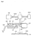
- FIG. 3 is a perspective view showing a construction of an image recording apparatus in a second embodiment of this invention.
- Fig. 4 is a schematic sectional view of a principal portion of the apparatus.
- a cylindrical drum 101 is supported on a base (not shown).
- a recording material 110 is fixed to the inner peripheral surface 101A of cylindrical drum 101.
- the inner peripheral surface 101A of cylindrical drum 101 is in the form of a hollow half cylinder opening at opposite ends and at top.
- a pair of supports 101B and 101C are arranged at opposite sides of the cylindrical drum 101.
- a secondary scan base 101D is mounted to bridge the supports 101B and 101C.
- the secondary scan base 101D has, arranged thereon, a secondary san motor 102, two rails 102A extending axially of the motor 102, a ball screw 102B having one end thereof attached to a shaft of the motor 102, and a flange 102C rotatably supporting the other end of the ball screw 102B.
- An arm 102D is attached to the ball screw 102 to be movable along the rails 102A.
- the arm 102D has a recording head 103 secured to a distal, lower end thereof.
- the recording head 103 includes a deflector 134 rotatable in a direction of arrow X by a primary scan motor 133.
- the recording head 103 includes an imaging optical system 112 for emitting light beams toward the deflector 134.
- the deflector 134 causes the light beams emitted from the imaging optical system 112 to scan the cylindrical drum 101 circumferentially.
- the recording head 103 is driven by the secondary scan motor 102 to move in a secondary scanning direction Y synchronously with primary scanning action of the light beams caused by the deflector 134.
- the imaging optical system 112 of recording head 103 receives light beams from numerous semiconductor lasers 127 fixedly arranged outside the cylindrical drum 101.
- the light beams are guided by the following optical elements. Specifically, a laser beam emitted from each semiconductor laser 127 is guided to the imaging optical system 112 that is fixed to the recording head 103, by a step index type multi-mode optical fiber 131 connected to the semiconductor laser 127, a graded index type multi-mode optical fiber 132 connected to the step index type multi-mode optical fiber 131 at a connecting unit 126, a branch box 125 that gathers a plurality of optical fibers 132 into a fiber bundle 124, a step index type multi-mode optical fiber 133 connected to each graded index type multi-mode optical fiber 132 of the fiber bundle 124 at an optical fiber connecting unit 123, a fiber bundle 122 of a plurality of step index type multi-mode optical fibers 133, and a light emitter 121 formed at the other end of fiber bundle 122.
- the graded index type multi-mode optical fibers 132 and step index type multi-mode optical fibers 133 are connected to each other inside the optical fiber connecting unit 123 by fusing their ends together so that the cores abut with each other. However, these fibers may be connected mechanically.
- the optical fiber connecting unit 123, the fiber bundle 122 of step index type multi-mode optical fibers 133 and the light emitter 121 are fixed to the recording head 103.
- the fiber bundle 124 of graded index type multi-mode optical fibers 132 is guided by a protective device 118 such as a cable bearer.
- the plurality of semiconductor lasers 127, step index type multi-mode optical fibers 131, connecting units 126, graded index type multi-mode optical fibers 132 and branch box 125 are fixed to a base not shown. Thus, these components are free from influences of the movement in the secondary scanning direction of the recording head 103.
- the graded index type multi-mode optical fibers 132 are used in the part movable with the recording head 103. This arrangement precludes the problem that speckles of the light beams move at the exit end with variations in the mode of light propagation.
- the step index type multi-mode optical fibers 131 are used in the location not influenced by the movement of the recording head 103. This arrangement is free from the problem that speckles of the light beams move at the exit end with variations in the mode of light propagation occurring with movement of the recording head 103. Since the laser beam spreads over the entire core diameter, the step index type multi-mode optical fibers 133 have a substantially uniform light quantity distribution, and the laser beam may be projected in a reduced size onto the recording material 110 effectively.
Landscapes
- Health & Medical Sciences (AREA)
- General Health & Medical Sciences (AREA)
- Toxicology (AREA)
- Optical Couplings Of Light Guides (AREA)
- Electronic Switches (AREA)
- Facsimile Scanning Arrangements (AREA)
- Optical Fibers, Optical Fiber Cores, And Optical Fiber Bundles (AREA)
- Printers Or Recording Devices Using Electromagnetic And Radiation Means (AREA)
- Facsimile Heads (AREA)
- Optical Head (AREA)
- Mechanical Optical Scanning Systems (AREA)
Claims (6)
- Bildaufzeichnungsgerät, welches ein Bild durch Leiten von Licht, das von einer an einem Hauptgehäuse des Geräts befestigten Lichtquelle (27, 127) emittiert wird, durch optische Fasern zu einem Aufzeichnungskopf (12, 103), der in Bezug auf ein Aufzeichnungsmaterial (10, 110) beweglich ist, aufzeichnet, wobei die optischen Fasern umfassen:eine optische Multimode-Faser vom Stufenindex-Typ (32, 132), die mit der Bewegung des Aufzeichnungskopfs (12, 103) verformbar und bewegbar ist; undeine optische Multimode-Faser vom Schrittindex-Typ (33, 133), welche einen Lichtemitter (21) an einem ihrer Enden bildet, um Licht in Richtung des Aufzeichnungsmaterials (10, 110) zu emittieren, und deren anderes Ende mit der optischen Multimode-Faser vom Stufenindex-Typ (32, 132) verbunden ist, dadurch gekennzeichnet, dassdie optische Multimode-Faser vom Schrittindex-Typ (33, 133) einen Teil des Aufzeichnungskopfs bildet.
- Bildaufzeichnungsgerät gemäß Anspruch 1, wobei die optische Faser ferner umfasst:eine optische Multimode-Faser (31, 131), die mit den Lichtquellen (27, 127) verbunden ist,wobei ein Ende der optischen Multimode-Faser vom Stufenindex-Typ (32, 132) unbeweglich an einer der optischen Multimode-Fasern (31, 131) fixiert und mit dieser verbunden ist.
- Bildaufzeichnungsgerät gemäß Anspruch 2, wobei die optische Multimode-Faser (31, 131) eine optische Multimode-Faser vom Schrittindex-Typ ist.
- Bildaufzeichnungsgerät gemäß Anspruch 1, wobei die optische Multimode-Faser vom Stufenindex-Typ (32, 132) und die optische Multimode-Faser vom Schrittindex-Typ (33, 133), die an einem ihrer Enden einen Lichtemitter bildet, an einer Optischen-Faser-Verbindungseinheit (23, 123), die auf dem Aufzeichnungskopf (12, 103) angeordnet ist, miteinander verbunden sind.
- Bildaufzeichnungsgerät gemäß Anspruch 1, wobei:das Aufzeichnungsmaterial (10) auf einer Aufzeichnungstrommel (11), die um ihre Achse drehbar ist, befestigt ist; undder Aufzeichnungskopf (12) parallel zu der Achse der Aufzeichnungstrommel (11) bewegbar ist.
- Bildaufzeichnungsgerät gemäß Anspruch 1, wobei:das Aufzeichnungsmaterial (110) auf einer inneren peripheren Oberfläche (101A) in Form eines hohlen Halbzylinders einer Trommel mit zylindrischer Innenfläche (101) befestigt ist; undder Aufzeichnungskopf (103) parallel zu einer Achse der Trommel mit zylindrischer Innenfläche (101) bewegbar ist und einen Deflektor (134) aufweist, der bewirkt, dass ein Lichtstrahl, der von der optischen Multimode-Faser vom Schrittindex-Typ (133) emittiert wird, die Trommel mit zylindrischer Innenfläche (101) umlaufend abtastet.
Applications Claiming Priority (1)
| Application Number | Priority Date | Filing Date | Title |
|---|---|---|---|
| JP2005354434A JP4671851B2 (ja) | 2005-12-08 | 2005-12-08 | 画像記録装置 |
Publications (3)
| Publication Number | Publication Date |
|---|---|
| EP1795360A2 EP1795360A2 (de) | 2007-06-13 |
| EP1795360A3 EP1795360A3 (de) | 2007-12-26 |
| EP1795360B1 true EP1795360B1 (de) | 2014-05-07 |
Family
ID=37866040
Family Applications (1)
| Application Number | Title | Priority Date | Filing Date |
|---|---|---|---|
| EP06025143.6A Not-in-force EP1795360B1 (de) | 2005-12-08 | 2006-12-05 | Bildaufzeichnungsgerät |
Country Status (3)
| Country | Link |
|---|---|
| US (1) | US7671883B2 (de) |
| EP (1) | EP1795360B1 (de) |
| JP (1) | JP4671851B2 (de) |
Families Citing this family (1)
| Publication number | Priority date | Publication date | Assignee | Title |
|---|---|---|---|---|
| DE102006008080A1 (de) * | 2006-02-22 | 2007-08-30 | Kleo Maschinenbau Ag | Belichtungsanlage |
Family Cites Families (18)
| Publication number | Priority date | Publication date | Assignee | Title |
|---|---|---|---|---|
| JPS59211830A (ja) | 1983-05-17 | 1984-11-30 | Sumitomo Heavy Ind Ltd | 印刷機の湿し水計測装置 |
| DE3479832D1 (en) * | 1983-05-17 | 1989-10-26 | Sumitomo Heavy Industries | Method of an apparatus for measuring dampening water for printing machine |
| JPH05208481A (ja) | 1992-01-31 | 1993-08-20 | Toppan Moore Co Ltd | オフセット印刷機の湿し水供給装置 |
| JPH08145630A (ja) * | 1994-11-25 | 1996-06-07 | Stump Bohr Gmbh | 建物又は土地等の監視装置 |
| DE69721003T2 (de) * | 1997-11-10 | 2004-01-22 | Fujifilm Electronic Imaging Ltd. | Verfahren und Gerät zur Belichtung eines Bildaufzeichnungsmediums |
| US6233001B1 (en) * | 1998-06-04 | 2001-05-15 | Fuji Photo Film Co., Ltd. | Image recording apparatus |
| US6211897B1 (en) | 1998-11-05 | 2001-04-03 | Eastman Kodak Company | Printing system and method for improving print quality of laser thermal printers |
| JP2000318130A (ja) | 1999-05-17 | 2000-11-21 | Toppan Printing Co Ltd | インキ量水量制御機能付きオフセット印刷機 |
| JP2002351086A (ja) * | 2001-03-22 | 2002-12-04 | Fuji Photo Film Co Ltd | 露光装置 |
| JP3808327B2 (ja) * | 2001-06-13 | 2006-08-09 | 大日本スクリーン製造株式会社 | 画像記録装置 |
| JP2003237128A (ja) | 2002-02-18 | 2003-08-27 | Fuji Photo Film Co Ltd | 露光装置 |
| JP2003279758A (ja) * | 2002-03-25 | 2003-10-02 | Hoya Photonics Corp | フェムト秒レーザ伝送用ファイバ,フェムト秒レーザ伝送用ファイバを使用したレーザ加工装置及びレーザ加工方法。 |
| US6960035B2 (en) * | 2002-04-10 | 2005-11-01 | Fuji Photo Film Co., Ltd. | Laser apparatus, exposure head, exposure apparatus, and optical fiber connection method |
| US6810175B1 (en) * | 2002-04-22 | 2004-10-26 | Terabeam Corporation | Off-axis mode scrambler |
| JP2004063931A (ja) * | 2002-07-31 | 2004-02-26 | Kyocera Corp | 光増幅ファイバ |
| US6876494B2 (en) * | 2002-09-30 | 2005-04-05 | Fuji Photo Film Co., Ltd. | Imaging forming apparatus |
| JP2005262760A (ja) | 2004-03-19 | 2005-09-29 | Mitsubishi Heavy Ind Ltd | オフセット印刷機の印刷装置 |
| JP2005331879A (ja) * | 2004-05-21 | 2005-12-02 | Seiko Epson Corp | 光モジュール、光通信装置及び電子機器 |
-
2005
- 2005-12-08 JP JP2005354434A patent/JP4671851B2/ja not_active Expired - Fee Related
-
2006
- 2006-12-05 EP EP06025143.6A patent/EP1795360B1/de not_active Not-in-force
- 2006-12-05 US US11/633,585 patent/US7671883B2/en not_active Expired - Fee Related
Also Published As
| Publication number | Publication date |
|---|---|
| JP4671851B2 (ja) | 2011-04-20 |
| EP1795360A3 (de) | 2007-12-26 |
| JP2007152864A (ja) | 2007-06-21 |
| US20070132832A1 (en) | 2007-06-14 |
| EP1795360A2 (de) | 2007-06-13 |
| US7671883B2 (en) | 2010-03-02 |
Similar Documents
| Publication | Publication Date | Title |
|---|---|---|
| JP3825995B2 (ja) | 光走査装置、マルチビーム走査装置及びそれを用いた画像形成装置 | |
| EP1810070B1 (de) | Optischer pfad mit einem strahlformer | |
| KR20030017433A (ko) | 주사형 광학장치와 이를 이용한 화상형성장치 | |
| US7715060B2 (en) | Image reading apparatus | |
| JP3808327B2 (ja) | 画像記録装置 | |
| US4746180A (en) | Device for light transmission | |
| JP4564620B2 (ja) | 走査光学装置及びそれを用いた画像形成装置 | |
| EP1795360B1 (de) | Bildaufzeichnungsgerät | |
| US7122780B2 (en) | Exposure apparatus with efficient uniform light output | |
| JPH1158665A (ja) | レーザ製版装置 | |
| JP4316829B2 (ja) | 露光装置及び結像倍率調整方法 | |
| JPH09281420A (ja) | レーザビーム走査光学装置 | |
| US4523805A (en) | Device for transferring information through fiberoptic bundles without distortion of information transferred therethrough | |
| JP2002286914A (ja) | イメージ作成装置 | |
| JP2007152864A5 (de) | ||
| EP1714790B1 (de) | Bilderzeugungsgerät | |
| EP3771936A1 (de) | Lasereinheit, lasermarkierer und laserdrucksystem | |
| US6233001B1 (en) | Image recording apparatus | |
| DE69803124T2 (de) | Aufzeichnungsabtaster | |
| US6115056A (en) | Focusing adjustment apparatus | |
| JP2004233749A (ja) | パターン描画装置用照明システムおよびパターン描画装置 | |
| JP2007045094A (ja) | 走査光学系及びそれを用いた画像形成装置 | |
| US6731852B2 (en) | Slack storage apparatus for optical fibers | |
| CN114770942A (zh) | 一种3d光固化打印机 | |
| JP3945954B2 (ja) | 書き込み光学系およびこれを用いた画像形成装置 |
Legal Events
| Date | Code | Title | Description |
|---|---|---|---|
| PUAI | Public reference made under article 153(3) epc to a published international application that has entered the european phase |
Free format text: ORIGINAL CODE: 0009012 |
|
| AK | Designated contracting states |
Kind code of ref document: A2 Designated state(s): AT BE BG CH CY CZ DE DK EE ES FI FR GB GR HU IE IS IT LI LT LU LV MC NL PL PT RO SE SI SK TR |
|
| AX | Request for extension of the european patent |
Extension state: AL BA HR MK YU |
|
| PUAL | Search report despatched |
Free format text: ORIGINAL CODE: 0009013 |
|
| AK | Designated contracting states |
Kind code of ref document: A3 Designated state(s): AT BE BG CH CY CZ DE DK EE ES FI FR GB GR HU IE IS IT LI LT LU LV MC NL PL PT RO SE SI SK TR |
|
| AX | Request for extension of the european patent |
Extension state: AL BA HR MK YU |
|
| RIC1 | Information provided on ipc code assigned before grant |
Ipc: B41J 2/46 20060101AFI20071122BHEP Ipc: B41J 2/455 20060101ALI20071122BHEP |
|
| 17P | Request for examination filed |
Effective date: 20080326 |
|
| AKX | Designation fees paid |
Designated state(s): AT BE BG CH CY CZ DE DK EE ES FI FR GB GR HU IE IS IT LI LT LU LV MC NL PL PT RO SE SI SK TR |
|
| 17Q | First examination report despatched |
Effective date: 20081212 |
|
| GRAP | Despatch of communication of intention to grant a patent |
Free format text: ORIGINAL CODE: EPIDOSNIGR1 |
|
| INTG | Intention to grant announced |
Effective date: 20140110 |
|
| RIN1 | Information on inventor provided before grant (corrected) |
Inventor name: KATAYAMA, TAKESHI Inventor name: OKA, JUNICHI |
|
| GRAS | Grant fee paid |
Free format text: ORIGINAL CODE: EPIDOSNIGR3 |
|
| GRAA | (expected) grant |
Free format text: ORIGINAL CODE: 0009210 |
|
| AK | Designated contracting states |
Kind code of ref document: B1 Designated state(s): AT BE BG CH CY CZ DE DK EE ES FI FR GB GR HU IE IS IT LI LT LU LV MC NL PL PT RO SE SI SK TR |
|
| REG | Reference to a national code |
Ref country code: GB Ref legal event code: FG4D |
|
| RIN1 | Information on inventor provided before grant (corrected) |
Inventor name: OKA, JUNICHI Inventor name: KATAYAMA, TAKESHI |
|
| REG | Reference to a national code |
Ref country code: AT Ref legal event code: REF Ref document number: 666313 Country of ref document: AT Kind code of ref document: T Effective date: 20140515 |
|
| REG | Reference to a national code |
Ref country code: IE Ref legal event code: FG4D |
|
| REG | Reference to a national code |
Ref country code: DE Ref legal event code: R096 Ref document number: 602006041402 Country of ref document: DE Effective date: 20140618 |
|
| REG | Reference to a national code |
Ref country code: AT Ref legal event code: MK05 Ref document number: 666313 Country of ref document: AT Kind code of ref document: T Effective date: 20140507 |
|
| REG | Reference to a national code |
Ref country code: NL Ref legal event code: VDEP Effective date: 20140507 |
|
| REG | Reference to a national code |
Ref country code: LT Ref legal event code: MG4D |
|
| PG25 | Lapsed in a contracting state [announced via postgrant information from national office to epo] |
Ref country code: GR Free format text: LAPSE BECAUSE OF FAILURE TO SUBMIT A TRANSLATION OF THE DESCRIPTION OR TO PAY THE FEE WITHIN THE PRESCRIBED TIME-LIMIT Effective date: 20140808 Ref country code: IS Free format text: LAPSE BECAUSE OF FAILURE TO SUBMIT A TRANSLATION OF THE DESCRIPTION OR TO PAY THE FEE WITHIN THE PRESCRIBED TIME-LIMIT Effective date: 20140907 Ref country code: CY Free format text: LAPSE BECAUSE OF FAILURE TO SUBMIT A TRANSLATION OF THE DESCRIPTION OR TO PAY THE FEE WITHIN THE PRESCRIBED TIME-LIMIT Effective date: 20140507 Ref country code: LT Free format text: LAPSE BECAUSE OF FAILURE TO SUBMIT A TRANSLATION OF THE DESCRIPTION OR TO PAY THE FEE WITHIN THE PRESCRIBED TIME-LIMIT Effective date: 20140507 Ref country code: FI Free format text: LAPSE BECAUSE OF FAILURE TO SUBMIT A TRANSLATION OF THE DESCRIPTION OR TO PAY THE FEE WITHIN THE PRESCRIBED TIME-LIMIT Effective date: 20140507 |
|
| PG25 | Lapsed in a contracting state [announced via postgrant information from national office to epo] |
Ref country code: ES Free format text: LAPSE BECAUSE OF FAILURE TO SUBMIT A TRANSLATION OF THE DESCRIPTION OR TO PAY THE FEE WITHIN THE PRESCRIBED TIME-LIMIT Effective date: 20140507 Ref country code: PL Free format text: LAPSE BECAUSE OF FAILURE TO SUBMIT A TRANSLATION OF THE DESCRIPTION OR TO PAY THE FEE WITHIN THE PRESCRIBED TIME-LIMIT Effective date: 20140507 Ref country code: LV Free format text: LAPSE BECAUSE OF FAILURE TO SUBMIT A TRANSLATION OF THE DESCRIPTION OR TO PAY THE FEE WITHIN THE PRESCRIBED TIME-LIMIT Effective date: 20140507 Ref country code: SE Free format text: LAPSE BECAUSE OF FAILURE TO SUBMIT A TRANSLATION OF THE DESCRIPTION OR TO PAY THE FEE WITHIN THE PRESCRIBED TIME-LIMIT Effective date: 20140507 Ref country code: AT Free format text: LAPSE BECAUSE OF FAILURE TO SUBMIT A TRANSLATION OF THE DESCRIPTION OR TO PAY THE FEE WITHIN THE PRESCRIBED TIME-LIMIT Effective date: 20140507 |
|
| PG25 | Lapsed in a contracting state [announced via postgrant information from national office to epo] |
Ref country code: PT Free format text: LAPSE BECAUSE OF FAILURE TO SUBMIT A TRANSLATION OF THE DESCRIPTION OR TO PAY THE FEE WITHIN THE PRESCRIBED TIME-LIMIT Effective date: 20140908 |
|
| PG25 | Lapsed in a contracting state [announced via postgrant information from national office to epo] |
Ref country code: DK Free format text: LAPSE BECAUSE OF FAILURE TO SUBMIT A TRANSLATION OF THE DESCRIPTION OR TO PAY THE FEE WITHIN THE PRESCRIBED TIME-LIMIT Effective date: 20140507 Ref country code: EE Free format text: LAPSE BECAUSE OF FAILURE TO SUBMIT A TRANSLATION OF THE DESCRIPTION OR TO PAY THE FEE WITHIN THE PRESCRIBED TIME-LIMIT Effective date: 20140507 Ref country code: RO Free format text: LAPSE BECAUSE OF FAILURE TO SUBMIT A TRANSLATION OF THE DESCRIPTION OR TO PAY THE FEE WITHIN THE PRESCRIBED TIME-LIMIT Effective date: 20140507 Ref country code: CZ Free format text: LAPSE BECAUSE OF FAILURE TO SUBMIT A TRANSLATION OF THE DESCRIPTION OR TO PAY THE FEE WITHIN THE PRESCRIBED TIME-LIMIT Effective date: 20140507 Ref country code: SK Free format text: LAPSE BECAUSE OF FAILURE TO SUBMIT A TRANSLATION OF THE DESCRIPTION OR TO PAY THE FEE WITHIN THE PRESCRIBED TIME-LIMIT Effective date: 20140507 Ref country code: BE Free format text: LAPSE BECAUSE OF FAILURE TO SUBMIT A TRANSLATION OF THE DESCRIPTION OR TO PAY THE FEE WITHIN THE PRESCRIBED TIME-LIMIT Effective date: 20140507 |
|
| PGFP | Annual fee paid to national office [announced via postgrant information from national office to epo] |
Ref country code: GB Payment date: 20141224 Year of fee payment: 9 |
|
| REG | Reference to a national code |
Ref country code: DE Ref legal event code: R097 Ref document number: 602006041402 Country of ref document: DE |
|
| PG25 | Lapsed in a contracting state [announced via postgrant information from national office to epo] |
Ref country code: NL Free format text: LAPSE BECAUSE OF FAILURE TO SUBMIT A TRANSLATION OF THE DESCRIPTION OR TO PAY THE FEE WITHIN THE PRESCRIBED TIME-LIMIT Effective date: 20140507 |
|
| PLBE | No opposition filed within time limit |
Free format text: ORIGINAL CODE: 0009261 |
|
| STAA | Information on the status of an ep patent application or granted ep patent |
Free format text: STATUS: NO OPPOSITION FILED WITHIN TIME LIMIT |
|
| REG | Reference to a national code |
Ref country code: DE Ref legal event code: R082 Ref document number: 602006041402 Country of ref document: DE Representative=s name: KILIAN KILIAN & PARTNER, DE |
|
| 26N | No opposition filed |
Effective date: 20150210 |
|
| REG | Reference to a national code |
Ref country code: DE Ref legal event code: R082 Ref document number: 602006041402 Country of ref document: DE Representative=s name: KILIAN KILIAN & PARTNER, DE Effective date: 20150317 Ref country code: DE Ref legal event code: R081 Ref document number: 602006041402 Country of ref document: DE Owner name: SCREEN HOLDINGS CO., LTD., JP Free format text: FORMER OWNER: DAINIPPON SCREEN MFG. CO., LTD., KYOTO, JP Effective date: 20140509 Ref country code: DE Ref legal event code: R081 Ref document number: 602006041402 Country of ref document: DE Owner name: SCREEN HOLDINGS CO., LTD., JP Free format text: FORMER OWNER: DAINIPPON SCREEN MFG. CO., LTD., KYOTO, JP Effective date: 20150317 Ref country code: DE Ref legal event code: R082 Ref document number: 602006041402 Country of ref document: DE Representative=s name: KILIAN KILIAN & PARTNER MBB PATENTANWAELTE, DE Effective date: 20150317 |
|
| PG25 | Lapsed in a contracting state [announced via postgrant information from national office to epo] |
Ref country code: IT Free format text: LAPSE BECAUSE OF FAILURE TO SUBMIT A TRANSLATION OF THE DESCRIPTION OR TO PAY THE FEE WITHIN THE PRESCRIBED TIME-LIMIT Effective date: 20140507 |
|
| REG | Reference to a national code |
Ref country code: DE Ref legal event code: R097 Ref document number: 602006041402 Country of ref document: DE Effective date: 20150210 |
|
| PGFP | Annual fee paid to national office [announced via postgrant information from national office to epo] |
Ref country code: FR Payment date: 20141222 Year of fee payment: 9 |
|
| REG | Reference to a national code |
Ref country code: FR Ref legal event code: CD Owner name: SCREEN HOLDINGS CO., LTD. Effective date: 20150622 |
|
| PG25 | Lapsed in a contracting state [announced via postgrant information from national office to epo] |
Ref country code: LU Free format text: LAPSE BECAUSE OF FAILURE TO SUBMIT A TRANSLATION OF THE DESCRIPTION OR TO PAY THE FEE WITHIN THE PRESCRIBED TIME-LIMIT Effective date: 20141205 Ref country code: SI Free format text: LAPSE BECAUSE OF FAILURE TO SUBMIT A TRANSLATION OF THE DESCRIPTION OR TO PAY THE FEE WITHIN THE PRESCRIBED TIME-LIMIT Effective date: 20140507 |
|
| REG | Reference to a national code |
Ref country code: CH Ref legal event code: PL |
|
| REG | Reference to a national code |
Ref country code: IE Ref legal event code: MM4A |
|
| PG25 | Lapsed in a contracting state [announced via postgrant information from national office to epo] |
Ref country code: CH Free format text: LAPSE BECAUSE OF NON-PAYMENT OF DUE FEES Effective date: 20141231 Ref country code: IE Free format text: LAPSE BECAUSE OF NON-PAYMENT OF DUE FEES Effective date: 20141205 Ref country code: LI Free format text: LAPSE BECAUSE OF NON-PAYMENT OF DUE FEES Effective date: 20141231 |
|
| PGFP | Annual fee paid to national office [announced via postgrant information from national office to epo] |
Ref country code: DE Payment date: 20151201 Year of fee payment: 10 |
|
| PG25 | Lapsed in a contracting state [announced via postgrant information from national office to epo] |
Ref country code: BG Free format text: LAPSE BECAUSE OF FAILURE TO SUBMIT A TRANSLATION OF THE DESCRIPTION OR TO PAY THE FEE WITHIN THE PRESCRIBED TIME-LIMIT Effective date: 20140507 Ref country code: MC Free format text: LAPSE BECAUSE OF FAILURE TO SUBMIT A TRANSLATION OF THE DESCRIPTION OR TO PAY THE FEE WITHIN THE PRESCRIBED TIME-LIMIT Effective date: 20140507 |
|
| PG25 | Lapsed in a contracting state [announced via postgrant information from national office to epo] |
Ref country code: TR Free format text: LAPSE BECAUSE OF FAILURE TO SUBMIT A TRANSLATION OF THE DESCRIPTION OR TO PAY THE FEE WITHIN THE PRESCRIBED TIME-LIMIT Effective date: 20140507 Ref country code: HU Free format text: LAPSE BECAUSE OF FAILURE TO SUBMIT A TRANSLATION OF THE DESCRIPTION OR TO PAY THE FEE WITHIN THE PRESCRIBED TIME-LIMIT; INVALID AB INITIO Effective date: 20061205 |
|
| GBPC | Gb: european patent ceased through non-payment of renewal fee |
Effective date: 20151205 |
|
| REG | Reference to a national code |
Ref country code: FR Ref legal event code: ST Effective date: 20160831 |
|
| PG25 | Lapsed in a contracting state [announced via postgrant information from national office to epo] |
Ref country code: GB Free format text: LAPSE BECAUSE OF NON-PAYMENT OF DUE FEES Effective date: 20151205 |
|
| PG25 | Lapsed in a contracting state [announced via postgrant information from national office to epo] |
Ref country code: FR Free format text: LAPSE BECAUSE OF NON-PAYMENT OF DUE FEES Effective date: 20151231 |
|
| REG | Reference to a national code |
Ref country code: DE Ref legal event code: R119 Ref document number: 602006041402 Country of ref document: DE |
|
| PG25 | Lapsed in a contracting state [announced via postgrant information from national office to epo] |
Ref country code: DE Free format text: LAPSE BECAUSE OF NON-PAYMENT OF DUE FEES Effective date: 20170701 |