EP1793214A1 - Anordnung zur berührungslosen Temperaturmessung an Rotoren - Google Patents
Anordnung zur berührungslosen Temperaturmessung an Rotoren Download PDFInfo
- Publication number
- EP1793214A1 EP1793214A1 EP06023138A EP06023138A EP1793214A1 EP 1793214 A1 EP1793214 A1 EP 1793214A1 EP 06023138 A EP06023138 A EP 06023138A EP 06023138 A EP06023138 A EP 06023138A EP 1793214 A1 EP1793214 A1 EP 1793214A1
- Authority
- EP
- European Patent Office
- Prior art keywords
- temperature
- rotor
- magnet
- voltage
- coils
- Prior art date
- Legal status (The legal status is an assumption and is not a legal conclusion. Google has not performed a legal analysis and makes no representation as to the accuracy of the status listed.)
- Granted
Links
Images



Classifications
-
- G—PHYSICS
- G01—MEASURING; TESTING
- G01K—MEASURING TEMPERATURE; MEASURING QUANTITY OF HEAT; THERMALLY-SENSITIVE ELEMENTS NOT OTHERWISE PROVIDED FOR
- G01K7/00—Measuring temperature based on the use of electric or magnetic elements directly sensitive to heat ; Power supply therefor, e.g. using thermoelectric elements
- G01K7/36—Measuring temperature based on the use of electric or magnetic elements directly sensitive to heat ; Power supply therefor, e.g. using thermoelectric elements using magnetic elements, e.g. magnets, coils
- G01K7/38—Measuring temperature based on the use of electric or magnetic elements directly sensitive to heat ; Power supply therefor, e.g. using thermoelectric elements using magnetic elements, e.g. magnets, coils the variations of temperature influencing the magnetic permeability
-
- G—PHYSICS
- G01—MEASURING; TESTING
- G01K—MEASURING TEMPERATURE; MEASURING QUANTITY OF HEAT; THERMALLY-SENSITIVE ELEMENTS NOT OTHERWISE PROVIDED FOR
- G01K13/00—Thermometers specially adapted for specific purposes
- G01K13/04—Thermometers specially adapted for specific purposes for measuring temperature of moving solid bodies
- G01K13/08—Thermometers specially adapted for specific purposes for measuring temperature of moving solid bodies in rotary movement
Definitions
- the invention relates to an arrangement for non-contact temperature measurement on rotors according to the preamble of the first claim.
- thermometry on moving objects is a widespread task in engineering. If the objects are rotors which revolve at very high speed, only non-contact measuring methods are possible. Additional constraints further limit the applicability of known measurement methods. Such a constraint may e.g. the operation be under vacuum. Representative of many applications are here called fast rotating mechanical vacuum pumps (e.g., turbomolecular pumps) and centrifuges. The importance of temperature measurement and monitoring becomes particularly clear with the example of the turbomolecular pump, in which certain rotor temperatures must not be exceeded for safe operation. For this, exact and reproducible temperature monitoring is indispensable.
- pyrometers are used for non-contact temperature measurement. These measure radiation emitted by the rotor as a measure of its temperature.
- An example of such an arrangement shows EP 1 348 940 A2 .
- the radiation received by sensors depends not only on the temperature but also very much on the surface condition of the rotor.
- the surface of a pump rotor when pumping vaporous media, in particular in the process technology by condensation; Deposit of solid particles or by chemical reactions is subject to changes, occur distortions of the temperature measurement.
- the dependence of the display on the ambient and housing temperature requires a complex Compensation electronics. The sometimes high sensitivity to high-energy, ionized radiation limits the range of application.
- the invention has for its object to provide a device for non-contact detection of temperatures on rotors, which provides a simple means exact and reproducible results and avoids the disadvantages described above.
- the arrangement according to the invention allows, in contrast to the prior art, to measure the temperature of the rotor over a wide range, for which, moreover, only a single arrangement is necessary.
- the temperature measurement is regardless of the Curie temperature of the ferromagnet, which reduces the problems in the production of the assembly, since the requirement of a constant and accurate Curie temperature over high quantities of ferromagnets is eliminated.
- the temperature measurement is also independent of the surface condition of the rotor and the stator, so that deposits play virtually no role.
- the temperature-proportional signal is a voltage, so that the further processing of the signal in an electronic system is simplified.
- Another embodiment is designed such that the operating temperature of the magnet is in the temperature range in which the dependence of the magnetization on the temperature is linear and reversible. This ensures that the measurement can be repeated almost as often as desired. Even after reaching a temperature limit, a further temperature determination is possible. The accuracy is increased and the conversion of the signal voltage into a temperature-proportional signal is simplified.
- the arrangement has a fixed gap between two coils, between which the ferromagnet moves on its circular path when circulating around the rotor axis. This measure increases the accuracy of the measurement, since in this way it is avoided that the gap between the magnet and the measuring coil changes. This change is generally caused by the material expansion of the rotor with increasing temperature.
- a plurality of coil pairs are arranged along the circular path, whereby the measurement accuracy can be further increased. These coil pairs are coupled in series or parallel connection.
- the temperature measurement it is advantageously possible for the temperature measurement to largely resort to components already present in the system in that the magnet for temperature measurement is a drive magnet.
- the magnet for temperature measurement is a drive magnet.
- the component cost is advantageously reduced significantly.
- the advantages of the arrangement according to the invention are particularly pronounced when used in a turbomolecular pump with fast-rotating rotor, since the arrangement has few components on the rotor. This makes it possible to place them at different points of the rotor, thus allowing greater freedom in the choice of the location. Also advantageous is the embodiment with a constant gap, since this eliminates the influence of heat-induced changes in length. These occur especially in turbomolecular pumps, because the rotor operates largely in the atmosphere-free space and therefore can give off its heat poor. Furthermore, the immunity against deposition of particles on the surface of the arrangement in a turbomolecular pump is particularly advantageous because these pumps are often used in process technology.
- FIG. 1 shows a diagram of the dependence of the magnetic polarization M (magnetization) of a permanent magnet on the temperature T, in the present case the rotor temperature.
- This temperature dependence follows the curve 1.
- the magnetic polarization decreases. In region I, this decrease is very linear and also reversible. In area II it falls off more and more, until finally there is no more polarization.
- This point 2 occurs at the material-specific Curie temperature T C.
- the magnets of the arrangement according to the invention are used in the region I.
- a first suitable erfmdungswashe arrangement for measuring the temperature is shown in Figure 2.
- the rotor has a shaft 201 and a disk-shaped part 202. On this disk-shaped part is seated a ring 203, in which at one point of the circumference a ferromagnet 204 is arranged. Alternatively, instead of a ring, an elevation may be provided to which ferromagnet is attached. Due to the rotation of the rotor this runs on a path around the rotor axis. In this orbit, he passes the coil 205, in which then at the moment of flyby a voltage is induced. This voltage is measured by the voltage measuring electronics 207 and converted by a part 208 of the electronics into a temperature-proportional signal.
- This signal is then available, for example, to a microcontroller 209 for further processing.
- This first measuring arrangement can be improved by arranging a second coil 206 at a fixed distance from the first coil 205 in such a way that the magnet 204 on the circular path passes through the gap between the coils.
- a significantly improved accuracy is achieved as follows: When heated, the rotor and in particular the disk 202 expands. As a result, the distance of the ferromagnet 204 to the axis of rotation increases, it flies thereby closer to the coil 205 over, the air gap decreases. If, however, a second coil 206 is arranged as shown, the distance to the coil 205 decreases, while the distance to the coil 206 increases, so that the total air gap is constant. Thus, the induced signal is independent of the disturbance rotor displacement.
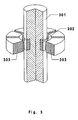
- FIG. 3 shows the shaft 301 of a rotor. Permanent magnets 302 are mounted on it. Coils 303 generate a magnetic field which rotates the shaft by suitable energization of the coils. A device that does this is shown in FIG. With 403 three coils of the drive are marked. These coils are energized by a drive electronics 402 in a conventional manner, wherein at any time one of the coils is de-energized. The de-energized coil can therefore serve as a detector coil for the voltage measuring device 405. This voltage is subsequently rectified by a rectifier circuit 406, so that a DC voltage is available to a microcontroller 409 as a temperature signal for further processing. A network electronics 401 serves to supply the drive electronics 402 with electrical energy.
Landscapes
- Physics & Mathematics (AREA)
- General Physics & Mathematics (AREA)
- Non-Positive Displacement Air Blowers (AREA)
- Measuring Temperature Or Quantity Of Heat (AREA)
Abstract
Description
- Die Erfindung betrifft eine Anordnung zur berührungslosen Temperaturmessung an Rotoren nach dem Oberbegriff des ersten Anspruchs.
- Die Messung von Temperaturen an sich bewegenden Objekten ist eine weit verbreitete Aufgabenstellung in der Technik. Wenn es sich bei den Objekten um Rotoren handelt, welche mit sehr hoher Drehzahl umlaufen, kommen nur berührungslose Messmethoden in Frage. Zusätzliche Randbedingungen schränken die Anwendbarkeit bekannte Messmethoden weiter ein. Eine solche Randbedingung kann z.B. der Betrieb unter Vakuum sein. Stellvertretend für viele Anwendungsfälle seien hier schnellrotierende mechanische Vakuumpumpen (z.B. Turbomolekularpumpen) und Zentrifugen genannt. Die Bedeutung der Temperaturmessung und Überwachung wird besonder am Beispiel der Turbomolekularpumpe deutlich, bei der für einen sicheren Betrieb bestimmte Rotortemperaturen nicht überschritten werden dürfen. Dafür ist eine exakte und reproduzierbare Temperaturüberwachung unabdingbar.
- In vielen Bereichen der Technik werden zur berührungslosen Temperaturmessung Pyrometer eingesetzt. Diese messen vom Rotor ausgehende Strahlung als Maß für dessen Temperatur. Ein Beispiel für eine solche Anordnung zeigt
EP 1 348 940 A2 . Die von Sensoren empfangene Strahlung hängt außer von der Temperatur auch sehr stark von der Oberflächenbeschaffenheit des Rotors ab. Da die Oberfläche eines Pumpenrotors beim Abpumpen von dampfförmigen Medien insbesondere in der Prozesstechnik durch Kondensation; Ablagerung von festen Partikeln oder auch durch chemische Resktionen Wandlungen unterworfen ist, treten Verfälschungen der Temperaturmessung auf. Außerdem erfordert die Abhängigkeit der Anzeige von der Umgebungs- und Gehäusetemperatur eine aufwändige Kompensationselektronik. Die zum Teil hohe Empfindlichkeit gegenüber energiereicher, ionisierter Strahlung beschränkt den Einsatzbereich. - In der
DE-OS 43 09 018 wird eine Anordnung zur berührungslosen Temperaturmessung an Rotoren beschrieben, bei der ferromagnetische Materialien eingesetzt werden. Diese ferromagnetischen Materialien werden auf dem Rotor der Anordnung befestigt und bilden mit weiteren Komponenten am Stator einen Magnetkreis. Dessen Eigenschaften ändern sich schlagartig, wenn die Curie-Temperatur des Ferromagneten überschritten wird. Diese Anordnung erlaubt nur, das Überschreiten der Curie-Temperatur festzustellen. Mehrere Temperaturen können nur bestimmt werden, indem mehrere solcher Ferromagnete mit unterschiedlicher Curie-Temperatur zum Einsatz kommen. Die Schwierigkeit beim serienmäßigen Einsatz einer solchen Anordnung liegt in der Beschaffung von ferromagnetischen Materialien mit reproduzierbarer Curie-Temperatur, Messungen über Temperaturbereiche sind nur mit erheblichem Aufwand und damit verbundenen Kosten möglich. - Der Erfindung liegt die Aufgabe zugrunde, eine Einrichtung zur berührungslosen Erfassung von Temperaturen an Rotoren vorzustellen, welche mit einachen Mitteln exakte und reproduzierbare Ergebnisse liefert und die oben beschriebenen Nachteile vermeidet.
- Die Aufgabe wird durch eine Anordnung mit den Merkmalen des ersten Anspruches gelöst. Die Ansprüche 2 bis 7 stellen vorteilhafte Weiterbildungen der Erfindung dar.
- Die erfindungsgemäße Anordnung erlaubt im Gegensatz zum Stand der Technik, die Temperatur des Rotors über einen weiten Bereich hinweg zu messen, wofür zudem nur eine einzige Anordnung notwendig ist. Die Temperaturmessung ist unabhängig von der Curie-Temperatur des Ferromagneten, was die Probleme bei der Produktion der Anordnung verringert, da die Anforderung einer konstanten und genauen Curie-Temperatur über hohe Stückzahlen von Ferromagneten entfällt. Die Temperaturmessung ist außerdem unabhängig von der Oberflächenbeschaffenheit des Rotors und des Stators, so dass Ablagerungen praktisch keine Rolle spielen.
- In einer Weiterbildung der Erfindung ist das temperaturproportionale Signal eine Spannung, so dass die Weiterverarbeitung des Signals in einer Elektronik vereinfacht ist.
- Eine weitere Ausführungsform ist so gestaltet, dass die Betriebstemperatur des Magneten in dem Temperaturbereich liegt, in dem die Abhängigkeit der Magnetisierung von der Temperatur linear und reversibel ist. Hierdurch wird erreicht, dass die Messung praktisch beliebig oft wiederholbar ist. Selbst nach Erreichen eines Temperaturgrenzwertes ist eine weitere Temperaturbestimmung möglich. Die Genauigkeit wird erhöht und die Umwandlung der Signalspannung in ein temperaturproportionales Signal vereinfacht.
- In einer Weiterbildung weist die Anordnung einen festen Spalt zwischen zwei Spulen auf, zwischen dem sich der Ferromagnet auf seiner Kreisbahn beim Umlauf um die Rotorachse hindurch bewegt. Diese Maßnahme erhöht die Genauigkeit der Messung, da auf diese Weise vermieden wird, dass sich der Spalt zwischen Magnet und Messspule ändert. Diese Änderung wird im Allgemeinen durch die Materialausdehnung des Rotors mit steigender Temperatur bewirkt.
- In einer weiteren Ausführungsform sind mehrere Spulenpaare entlang der Kreisbahn angeordnet, wodurch die Messgenauigkeit weiter erhöht werden kann. Diese Spulenpaare sind in Serien- oder Parallelschaltung gekoppelt.
- In einer anderen Ausführungsform ist es vorteilhaft möglich, zur Temperaturmessung weitgehend auf bereits im System befindliche Komponenten zurückzugreifen, indem der Magnet zur Temperaturmessung ein Antriebsmagnet ist. Dadurch, dass Motormagnet und Motorspulen verwendet werden, wird der Bauteilaufwand in vorteilhafter Weise erheblich reduziert.
- Die Vorteile der erfindungsgemäßen Anordnung sind besonders ausgeprägt beim Einsatz in einer Turbomolekularpumpe mit schnelldrehendem Rotor, da die Anordnung wenige Komponenten auf dem Rotor besitzt. Dies erlaubt es, sie an verschiedenen Stellen des Rotors zu platzieren, ermöglicht daher eine größere Freiheit bei der Wahl des Messortes. Ebenfalls vorteilhaft ist die Ausführungsform mit konstantem Spalt, da dieser den Einfluss der wärmebedingten Längenänderungen eliminiert. Diese treten gerade bei Turbomolekularpumpen auf, da der Rotor weitgehend im atmosphärefreien Raum arbeitet und daher seine Wärme schlecht abgeben kann. Weiterhin ist die Unempflindlichkeit gegen Ablagerung von Partikeln auf der Oberfläche der Anordnung bei einer Turbomolekularpumpe besonders vorteilhaft, da diese Pumpen oft in der Prozesstechnik eingesetzt werden.
- Im folgenden soll die Erfindung anhand von Figuren beispielhaft erläutert werden.
- Fig. 1:
- Diagramm, welches die Temperaturabhängigkeit der Magnetisierung eines Magneten zeigt.
- Fig. 2:
- Zeigt eine erste Messanordnung im Achsschnitt
- Fig. 3:
- Eine vorteilhafte Ausführungsform, die die Antriebsanordnung für eine Welle, beispielsweise in einer Turbomolekularpumpe, nutzt.
- Fig. 4:
- Prinzip der elektrischen Schaltung für die Anordnung nach Fig. 3.
- Figur 1 veranschaulicht in einem Diagramm die Abhängigkeit der magnetischen Polarisation M (Magnetisierung) eines Permanentmagneten von der Temperatur T, im vorliegenden Fall die Rotortemperatur. Diese Temperaturabhängigkeit folgt der Kurve 1. Mit zunehmender Temperatur nimmt die magnetische Polarisation ab. Im Bereich I ist diese Abnahme in sehr guter Näherung linear und außerdem reversibel. Im Bereich II fällt sie immer stärker ab, bis schließlich keine Polarisation mehr vorhanden ist. Dieser Punkt 2 tritt bei der materialspezifischen Curie-Temperatur TC ein. Vorteilhaft werden die Magnete der erfindungsgemäßen Anordnung im der Bereich I eingesetzt.
- Eine erste geeignete erfmdungsgemäße Anordnung zum Messen der Temperatur ist in Figur 2 dargestellt. Der Rotor weist eine Welle 201 und ein scheibenförmiges Teil 202 auf. Auf diesem scheibenförmigen Teil sitzt ein Ring 203, in dem an einer Stelle des Umfangs ein Ferromagnet 204 angeordnet ist. Alternativ kann statt einem Ring auch eine Erhebung vorgesehen sein, an der Ferromagnet angebracht ist. Durch die Rotation des Rotors läuft dieser auf einer Bahn um die Rotorachse. Auf dieser Umlaufbahn kommt er an der Spule 205 vorbei, in der dann im Moment des Vorbeiflugs eine Spannung induziert wird. Diese Spannung wird von der Spannungsmesselektronik 207 gemessen und von einem Teil 208 der Elektronik in ein temperaturproportionales Signal umgewandelt. Diese Signal steht dann beispielsweise einem Mikrocontroller 209 zur Weiterverarbeitung zur Verfügung. Diese erste Messanordnung kann dadurch verbessert werden, dass eine zweite Spule 206 in festem Abstand zur ersten Spule 205 derart angeordnet ist, dass der Magnet 204 auf der Kreisbahn den Zwischenraum zwischen den Spulen passiert. Hierdurch wird eine deutlich verbesserte Genauigkeit wie folgt erreicht: Bei einer Erwärmung dehnt sich der Rotor und insbesondere die Scheibe 202 aus. Hierdurch nimmt der Abstand des Ferromagneten 204 zur Rotationsachse zu, er fliegt dadurch näher an der Spule 205 vorbei, der Luftspalt nimmt ab. Wird nun eine zweite Spule 206 wie gezeigt angeordnet, nimmt zwar der Abstand zur Spule 205 ab, der Abstand zur Spule 206 hingegen zu, so dass der Luftspalt in der Summe konstant ist. Somit ist das induzierte Signal unabhängig von der Störgröße Rotorverschiebung.
- Eine zweite geeignete Messanordnung ist in den Figuren 3 und 4 gezeigt. In Figur 3 ist die Welle 301 eines Rotors dargestellt. Auf ihr befestigt sind Permanentmagnete 302. Spulen 303 erzeugen ein Magnetfeld, welches durch geeignete Bestromung der Spulen die Welle in Drehung versetzt. Eine Einrichtung, die dies leistet, ist in Figur 4 dargestellt. Mit 403 sind drei Spulen des Antriebs gekennzeichnet. Diese Spulen werden durch eine Antriebselektronik 402 in an sich bekannter Weise bestromt, wobei zu jedem Zeitpunkt eine der Spulen unbestromt ist. Die unbestromte Spule kann daher als Detektorspule für die Spannungsmesseinrichtung 405 dienen. Diese Spannung wird anschließend von einer Gleichrichterschaltung 406 gleichgerichtet, so dass einem Mikrocontroller 409 eine Gleichspannung als Temperatursignal zur Weiterverarbeitung zur Verfügung steht. Eine Netzelektronik 401 dient zur Versorgung der Antriebselektronik 402 mit elektrischer Energie.
Claims (7)
- Vorrichtung mit Rotor (201, 202) und Stator, mit einem Magneten (204, 302) auf dem Rotor und einer elektrischen Spule (205, 206), welche am Stator angeordnet ist, mit elektronischen Mitteln zur Messung einer an diesen Spulen anliegenden Signalspannung (207, 405), mit einem Antrieb, der den Rotor in Drehung versetzt, dadurch gekennzeichnet, dass als Signalspannung die von dem Magneten (204) in dieser Spule induzierte Spannung gemessen wird und die elektronischen Mittel so ausgebildet sind, dass sie die Spannung in ein temperaturproportionales Signal umwandeln.
- Vorrichtung nach Anpruch 1, dadurch gekennzeichnet, dass das temperaturproportionale Signal eine Spannung ist.
- Vorrichtung nach Anspruch 1 oder 2, dadurch gekennzeichnet, dass die Betriebstemperatur des Magneten (204) in dem Temperaturbereich liegt, in dem die Abhängigkeit der Magnetisierung von der Temperatur linear und reversibel ist.
- Vorrichtung nach einem der vorhergehenden Ansprüche, dadurch gekennzeichnet, dass der Magnet ein Antriebsmagnet (303, 403) ist.
- Vorrichtung nach einem der Ansprüche 1 bis 3, dadurch gekennzeichnet, dass sie zwei Spulen (205, 206) am Stator und einen Magneten (204) am Rotor aufweist, die so angeordnet sind, dass der Magnet auf seiner durch die Drehung des Rotors entstehende Kreisbahn den Zwischenraum zwischen den Spulen passiert.
- Vorrichtung nach Anspruch 5, dadurch gekennzeichnet, dass mehrere Spulenpaare entlang der Kreisbahn angeordnet sind.
- Turbomolekularvakuumpumpe, dadurch gekennzeichnet, dass sie eine Vorrichtung nach einem der Ansprüche 1 bis 6 aufweist.
Applications Claiming Priority (1)
| Application Number | Priority Date | Filing Date | Title |
|---|---|---|---|
| DE102005057641.9A DE102005057641B4 (de) | 2005-12-02 | 2005-12-02 | Turbomolekularvakuumpumpe mit berührungsloser Rotortemperaturmessung |
Publications (2)
| Publication Number | Publication Date |
|---|---|
| EP1793214A1 true EP1793214A1 (de) | 2007-06-06 |
| EP1793214B1 EP1793214B1 (de) | 2017-06-14 |
Family
ID=37746959
Family Applications (1)
| Application Number | Title | Priority Date | Filing Date |
|---|---|---|---|
| EP06023138.8A Not-in-force EP1793214B1 (de) | 2005-12-02 | 2006-11-07 | Anordnung zur berührungslosen Temperaturmessung an Rotoren |
Country Status (4)
| Country | Link |
|---|---|
| US (1) | US7575372B2 (de) |
| EP (1) | EP1793214B1 (de) |
| JP (1) | JP5117038B2 (de) |
| DE (1) | DE102005057641B4 (de) |
Cited By (2)
| Publication number | Priority date | Publication date | Assignee | Title |
|---|---|---|---|---|
| DE102008037157A1 (de) * | 2008-08-08 | 2010-02-11 | Oerlikon Textile Gmbh & Co. Kg | Verfahren zum Betreiben einer Rotorspinnmaschine |
| CN102403666A (zh) * | 2011-11-25 | 2012-04-04 | 浙江开关厂有限公司 | 可在线测量柜内温度的开关设备 |
Families Citing this family (6)
| Publication number | Priority date | Publication date | Assignee | Title |
|---|---|---|---|---|
| DE102007001065B4 (de) * | 2007-01-03 | 2021-07-22 | Leybold Gmbh | Gaspumpe |
| US7965054B2 (en) * | 2007-07-26 | 2011-06-21 | Shimadzu Corporation | Vacuum pump |
| EP2108930A1 (de) * | 2008-04-09 | 2009-10-14 | VARIAN S.p.A. | Berührungslose Messeinrichtung zum Messen von Parametern eines Rotors einer schnell rotierenden Maschine |
| WO2011106825A2 (en) * | 2010-03-01 | 2011-09-09 | Applidyne Australia Pty Ltd | Contactless temperature sensing |
| US9383267B2 (en) * | 2013-05-31 | 2016-07-05 | Purdue Research Foundation | Wireless sensor for rotating elements |
| CN104132736B (zh) | 2014-07-31 | 2017-02-15 | 华中科技大学 | 一种直流激励磁场下的非侵入式快速温度变化的测量方法 |
Citations (6)
| Publication number | Priority date | Publication date | Assignee | Title |
|---|---|---|---|---|
| US1742138A (en) * | 1924-11-28 | 1929-12-31 | Gen Electric | Temperature-responsive device |
| DE958600C (de) * | 1955-10-11 | 1957-02-21 | Licentia Gmbh | Anordnung zur Temperaturmessung an umlaufenden Wellen |
| GB1309906A (en) * | 1969-06-09 | 1973-03-14 | English Electric Co Ltd | Temperature sensors |
| DE2300167A1 (de) * | 1973-01-03 | 1974-07-18 | Ni I Ok I Avtom Tschernoj Meta | Einrichtung zur messung der temperatur ferromagnetischer koerper |
| FR2216570A1 (de) * | 1973-02-03 | 1974-08-30 | Eickhoff Geb | |
| DE4309018A1 (de) * | 1993-03-20 | 1994-09-22 | Balzers Pfeiffer Gmbh | Temperatur-Meßanordnung |
Family Cites Families (21)
| Publication number | Priority date | Publication date | Assignee | Title |
|---|---|---|---|---|
| DE946092C (de) * | 1941-08-27 | 1956-07-26 | Siemens Ag | Einrichtung zur Messung oder Regelung der Temperatur von rotierenden Koerpern |
| US3391576A (en) * | 1965-03-13 | 1968-07-09 | Hitachi Ltd | Thermometric device for rotating structures |
| GB1359574A (en) * | 1973-01-31 | 1974-07-10 | Davall Sons Ltd S Somervell R | Temperature sensors |
| JPS58180437U (ja) * | 1982-05-28 | 1983-12-02 | 東北金属工業株式会社 | 回転体の温度検出装置 |
| JPS59108960A (ja) * | 1982-12-14 | 1984-06-23 | Yaskawa Electric Mfg Co Ltd | 温度検出機能をもつ回転速度検出装置 |
| JPS60104740U (ja) * | 1983-12-21 | 1985-07-17 | シャープ株式会社 | 温度検出装置 |
| DE3416340A1 (de) * | 1984-05-03 | 1985-11-07 | Robert Bosch Gmbh, 7000 Stuttgart | Vorrichtung zur beruehrungslosen temperaturmessung von rotierenden koerpern |
| JPH04143644A (ja) * | 1990-10-05 | 1992-05-18 | Canon Inc | 電子素子用温度制御装置 |
| DE4133365C2 (de) * | 1991-10-09 | 1994-04-28 | Innotech Microelectronic Gmbh | Meßwertübertragungssystem |
| DE4137559A1 (de) * | 1991-11-15 | 1993-05-19 | Heidelberger Druckmasch Ag | Einrichtung zur erfassung mindestens einer zustandsgroesse eines buerstenlosen gleichstrommotors |
| JPH06117943A (ja) * | 1992-10-02 | 1994-04-28 | Canon Inc | 温度測定方法、該温度測定方法を用いた装置およびエネルギー貯蔵装置 |
| US5907202A (en) * | 1995-08-28 | 1999-05-25 | Mikuni Corporation | Thermo-sensitive actuator and idle speed controller employing the same |
| DE19616258C2 (de) * | 1996-04-24 | 2000-04-20 | Wolfgang Wuttke | Verfahren und Vorrichtung zur Überwachung des Wärmezustandes eines bewegten Körpers |
| DE19702140C2 (de) * | 1997-01-22 | 1998-12-03 | Siemens Ag | Vorrichtung und Verfahren zur Messung der Temperatur eines rotierenden Trägers |
| DE19739587B4 (de) * | 1997-09-10 | 2006-05-11 | Pfeiffer Vacuum Gmbh | Temperatur-Überwachungsanordnung |
| DE19857453B4 (de) * | 1998-12-12 | 2008-03-20 | Pfeiffer Vacuum Gmbh | Temperaturüberwachung an Rotoren von Vakuumpumpen |
| US6262574B1 (en) * | 1999-03-12 | 2001-07-17 | The United States Of America As Represented By The Secretary Of The Navy | Sensor for measuring magnetic field strength and temperature for an electric motor |
| US6424148B1 (en) * | 2000-10-30 | 2002-07-23 | Sauer-Danfoss Inc. | Apparatus and method for sensing and magnetically communicating physical parameters of rotating shaft |
| JP2003287463A (ja) * | 2002-03-28 | 2003-10-10 | Boc Edwards Technologies Ltd | 放射温度測定装置及び該放射温度測定装置を搭載したターボ分子ポンプ |
| US7023201B2 (en) * | 2003-12-15 | 2006-04-04 | Texas Instruments Incorporated | Magnetic position sensor apparatus and method |
| DE102004016477A1 (de) * | 2004-03-31 | 2005-10-20 | Fag Kugelfischer Ag | Vorrichtung zum Erfassen wenigstens eines Zustandes |
-
2005
- 2005-12-02 DE DE102005057641.9A patent/DE102005057641B4/de not_active Expired - Fee Related
-
2006
- 2006-11-07 EP EP06023138.8A patent/EP1793214B1/de not_active Not-in-force
- 2006-11-16 US US11/601,016 patent/US7575372B2/en not_active Expired - Fee Related
- 2006-11-30 JP JP2006323804A patent/JP5117038B2/ja not_active Expired - Fee Related
Patent Citations (6)
| Publication number | Priority date | Publication date | Assignee | Title |
|---|---|---|---|---|
| US1742138A (en) * | 1924-11-28 | 1929-12-31 | Gen Electric | Temperature-responsive device |
| DE958600C (de) * | 1955-10-11 | 1957-02-21 | Licentia Gmbh | Anordnung zur Temperaturmessung an umlaufenden Wellen |
| GB1309906A (en) * | 1969-06-09 | 1973-03-14 | English Electric Co Ltd | Temperature sensors |
| DE2300167A1 (de) * | 1973-01-03 | 1974-07-18 | Ni I Ok I Avtom Tschernoj Meta | Einrichtung zur messung der temperatur ferromagnetischer koerper |
| FR2216570A1 (de) * | 1973-02-03 | 1974-08-30 | Eickhoff Geb | |
| DE4309018A1 (de) * | 1993-03-20 | 1994-09-22 | Balzers Pfeiffer Gmbh | Temperatur-Meßanordnung |
Cited By (2)
| Publication number | Priority date | Publication date | Assignee | Title |
|---|---|---|---|---|
| DE102008037157A1 (de) * | 2008-08-08 | 2010-02-11 | Oerlikon Textile Gmbh & Co. Kg | Verfahren zum Betreiben einer Rotorspinnmaschine |
| CN102403666A (zh) * | 2011-11-25 | 2012-04-04 | 浙江开关厂有限公司 | 可在线测量柜内温度的开关设备 |
Also Published As
| Publication number | Publication date |
|---|---|
| JP5117038B2 (ja) | 2013-01-09 |
| US20070127551A1 (en) | 2007-06-07 |
| US7575372B2 (en) | 2009-08-18 |
| EP1793214B1 (de) | 2017-06-14 |
| DE102005057641A1 (de) | 2007-06-06 |
| DE102005057641B4 (de) | 2017-06-01 |
| JP2007155723A (ja) | 2007-06-21 |
Similar Documents
| Publication | Publication Date | Title |
|---|---|---|
| DE19739587B4 (de) | Temperatur-Überwachungsanordnung | |
| DE60318442T2 (de) | Mit einem sensor ausgestattetes wälzlager und damit ausgerüsteter elektromotor | |
| EP1128159A2 (de) | Mechanische Welle mit integrierter Magnetanordnung | |
| DE102010003475A1 (de) | Drehwinkel-messgerät und drehzahl-messgerät | |
| DE102005057641B4 (de) | Turbomolekularvakuumpumpe mit berührungsloser Rotortemperaturmessung | |
| EP2325654A1 (de) | Wälzlageranordnung mit einer Sensoreinheit | |
| DE102012200092A1 (de) | Sensorvorrichtung zur berührungslosen Erfassung einer Rotationseigenschaft eines drehbaren Gegenstandes | |
| EP2848816B1 (de) | Anordnung mit einer Turbomolekularpumpe sowie Verfahren zur Kompensation eines Magnetfeldes wenigstens eines in einer Turbomolekularpumpe angeordneten, ein magnetisches Störfeld erzeugenden Bauteiles | |
| EP3361102B1 (de) | Positionserfassungsvorrichtung | |
| DE4309018A1 (de) | Temperatur-Meßanordnung | |
| WO2015165456A1 (de) | Verfahren zur erkennung einer rotorlage eines elektromotors, ein target zur bestimmung der rotorlage des elektromotors und ein elektromotor | |
| WO2003055039A2 (de) | Spalttopfmotor | |
| DE102016226293A1 (de) | Bürstenlose elektrische Maschine | |
| DE69834881T2 (de) | Verfahren und Vorrichtung zum Erzeugen von Impulssignalen | |
| DE4324622A1 (de) | Vorrichtung zum Erfassen einer Drehbewegung | |
| DE19857453B4 (de) | Temperaturüberwachung an Rotoren von Vakuumpumpen | |
| DE2521163B1 (de) | Einrichtung zur ermittlung einer der drehzahl oder dem drehwinkel einer achse entsprechenden groesse | |
| EP3483451B1 (de) | Positionserfassungsvorrichtung für einen magnetgelagerten rotor | |
| EP1750101B1 (de) | Feldmodulierende Winkelmesseinrichtung und Verfahren zu deren Betrieb | |
| DE102018203409A1 (de) | Linearbewegungsvorrichtung und Verfahren | |
| EP0503501B1 (de) | Einrichtung zum Erfassen eines Walzenspaltes | |
| DE102014214706A1 (de) | Elektrowerkzeug mit einem Drehzahlerfassungssystem | |
| DE112009002025T5 (de) | Sensor mit variabler Reluktanz mit Rauschbeseitigung | |
| DE3839547A1 (de) | Wirbelstrommesswerk | |
| DE102007001065B4 (de) | Gaspumpe |
Legal Events
| Date | Code | Title | Description |
|---|---|---|---|
| PUAI | Public reference made under article 153(3) epc to a published international application that has entered the european phase |
Free format text: ORIGINAL CODE: 0009012 |
|
| AK | Designated contracting states |
Kind code of ref document: A1 Designated state(s): AT BE BG CH CY CZ DE DK EE ES FI FR GB GR HU IE IS IT LI LT LU LV MC NL PL PT RO SE SI SK TR |
|
| AX | Request for extension of the european patent |
Extension state: AL BA HR MK YU |
|
| 17P | Request for examination filed |
Effective date: 20071012 |
|
| 17Q | First examination report despatched |
Effective date: 20071119 |
|
| AKX | Designation fees paid |
Designated state(s): AT BE BG CH CY CZ DE DK EE ES FI FR GB GR HU IE IS IT LI LT LU LV MC NL PL PT RO SE SI SK TR |
|
| GRAP | Despatch of communication of intention to grant a patent |
Free format text: ORIGINAL CODE: EPIDOSNIGR1 |
|
| INTG | Intention to grant announced |
Effective date: 20161130 |
|
| GRAS | Grant fee paid |
Free format text: ORIGINAL CODE: EPIDOSNIGR3 |
|
| GRAJ | Information related to disapproval of communication of intention to grant by the applicant or resumption of examination proceedings by the epo deleted |
Free format text: ORIGINAL CODE: EPIDOSDIGR1 |
|
| GRAL | Information related to payment of fee for publishing/printing deleted |
Free format text: ORIGINAL CODE: EPIDOSDIGR3 |
|
| GRAP | Despatch of communication of intention to grant a patent |
Free format text: ORIGINAL CODE: EPIDOSNIGR1 |
|
| INTC | Intention to grant announced (deleted) | ||
| INTG | Intention to grant announced |
Effective date: 20170329 |
|
| GRAA | (expected) grant |
Free format text: ORIGINAL CODE: 0009210 |
|
| AK | Designated contracting states |
Kind code of ref document: B1 Designated state(s): AT BE BG CH CY CZ DE DK EE ES FI FR GB GR HU IE IS IT LI LT LU LV MC NL PL PT RO SE SI SK TR |
|
| REG | Reference to a national code |
Ref country code: GB Ref legal event code: FG4D Free format text: NOT ENGLISH |
|
| REG | Reference to a national code |
Ref country code: CH Ref legal event code: EP Ref country code: AT Ref legal event code: REF Ref document number: 901429 Country of ref document: AT Kind code of ref document: T Effective date: 20170615 |
|
| REG | Reference to a national code |
Ref country code: IE Ref legal event code: FG4D Free format text: LANGUAGE OF EP DOCUMENT: GERMAN |
|
| REG | Reference to a national code |
Ref country code: DE Ref legal event code: R096 Ref document number: 502006015540 Country of ref document: DE |
|
| REG | Reference to a national code |
Ref country code: NL Ref legal event code: MP Effective date: 20170614 |
|
| REG | Reference to a national code |
Ref country code: LT Ref legal event code: MG4D |
|
| PG25 | Lapsed in a contracting state [announced via postgrant information from national office to epo] |
Ref country code: ES Free format text: LAPSE BECAUSE OF FAILURE TO SUBMIT A TRANSLATION OF THE DESCRIPTION OR TO PAY THE FEE WITHIN THE PRESCRIBED TIME-LIMIT Effective date: 20170614 Ref country code: FI Free format text: LAPSE BECAUSE OF FAILURE TO SUBMIT A TRANSLATION OF THE DESCRIPTION OR TO PAY THE FEE WITHIN THE PRESCRIBED TIME-LIMIT Effective date: 20170614 Ref country code: LT Free format text: LAPSE BECAUSE OF FAILURE TO SUBMIT A TRANSLATION OF THE DESCRIPTION OR TO PAY THE FEE WITHIN THE PRESCRIBED TIME-LIMIT Effective date: 20170614 Ref country code: GR Free format text: LAPSE BECAUSE OF FAILURE TO SUBMIT A TRANSLATION OF THE DESCRIPTION OR TO PAY THE FEE WITHIN THE PRESCRIBED TIME-LIMIT Effective date: 20170915 |
|
| PG25 | Lapsed in a contracting state [announced via postgrant information from national office to epo] |
Ref country code: SE Free format text: LAPSE BECAUSE OF FAILURE TO SUBMIT A TRANSLATION OF THE DESCRIPTION OR TO PAY THE FEE WITHIN THE PRESCRIBED TIME-LIMIT Effective date: 20170614 Ref country code: LV Free format text: LAPSE BECAUSE OF FAILURE TO SUBMIT A TRANSLATION OF THE DESCRIPTION OR TO PAY THE FEE WITHIN THE PRESCRIBED TIME-LIMIT Effective date: 20170614 Ref country code: BG Free format text: LAPSE BECAUSE OF FAILURE TO SUBMIT A TRANSLATION OF THE DESCRIPTION OR TO PAY THE FEE WITHIN THE PRESCRIBED TIME-LIMIT Effective date: 20170914 Ref country code: NL Free format text: LAPSE BECAUSE OF FAILURE TO SUBMIT A TRANSLATION OF THE DESCRIPTION OR TO PAY THE FEE WITHIN THE PRESCRIBED TIME-LIMIT Effective date: 20170614 |
|
| PG25 | Lapsed in a contracting state [announced via postgrant information from national office to epo] |
Ref country code: SK Free format text: LAPSE BECAUSE OF FAILURE TO SUBMIT A TRANSLATION OF THE DESCRIPTION OR TO PAY THE FEE WITHIN THE PRESCRIBED TIME-LIMIT Effective date: 20170614 Ref country code: RO Free format text: LAPSE BECAUSE OF FAILURE TO SUBMIT A TRANSLATION OF THE DESCRIPTION OR TO PAY THE FEE WITHIN THE PRESCRIBED TIME-LIMIT Effective date: 20170614 Ref country code: EE Free format text: LAPSE BECAUSE OF FAILURE TO SUBMIT A TRANSLATION OF THE DESCRIPTION OR TO PAY THE FEE WITHIN THE PRESCRIBED TIME-LIMIT Effective date: 20170614 |
|
| REG | Reference to a national code |
Ref country code: FR Ref legal event code: PLFP Year of fee payment: 12 |
|
| PG25 | Lapsed in a contracting state [announced via postgrant information from national office to epo] |
Ref country code: PL Free format text: LAPSE BECAUSE OF FAILURE TO SUBMIT A TRANSLATION OF THE DESCRIPTION OR TO PAY THE FEE WITHIN THE PRESCRIBED TIME-LIMIT Effective date: 20170614 Ref country code: IS Free format text: LAPSE BECAUSE OF FAILURE TO SUBMIT A TRANSLATION OF THE DESCRIPTION OR TO PAY THE FEE WITHIN THE PRESCRIBED TIME-LIMIT Effective date: 20171014 |
|
| REG | Reference to a national code |
Ref country code: DE Ref legal event code: R097 Ref document number: 502006015540 Country of ref document: DE |
|
| PLBE | No opposition filed within time limit |
Free format text: ORIGINAL CODE: 0009261 |
|
| STAA | Information on the status of an ep patent application or granted ep patent |
Free format text: STATUS: NO OPPOSITION FILED WITHIN TIME LIMIT |
|
| PG25 | Lapsed in a contracting state [announced via postgrant information from national office to epo] |
Ref country code: DK Free format text: LAPSE BECAUSE OF FAILURE TO SUBMIT A TRANSLATION OF THE DESCRIPTION OR TO PAY THE FEE WITHIN THE PRESCRIBED TIME-LIMIT Effective date: 20170614 |
|
| 26N | No opposition filed |
Effective date: 20180315 |
|
| PG25 | Lapsed in a contracting state [announced via postgrant information from national office to epo] |
Ref country code: MC Free format text: LAPSE BECAUSE OF FAILURE TO SUBMIT A TRANSLATION OF THE DESCRIPTION OR TO PAY THE FEE WITHIN THE PRESCRIBED TIME-LIMIT Effective date: 20170614 |
|
| PG25 | Lapsed in a contracting state [announced via postgrant information from national office to epo] |
Ref country code: CH Free format text: LAPSE BECAUSE OF NON-PAYMENT OF DUE FEES Effective date: 20171130 Ref country code: LI Free format text: LAPSE BECAUSE OF NON-PAYMENT OF DUE FEES Effective date: 20171130 |
|
| PG25 | Lapsed in a contracting state [announced via postgrant information from national office to epo] |
Ref country code: LU Free format text: LAPSE BECAUSE OF NON-PAYMENT OF DUE FEES Effective date: 20171107 Ref country code: SI Free format text: LAPSE BECAUSE OF FAILURE TO SUBMIT A TRANSLATION OF THE DESCRIPTION OR TO PAY THE FEE WITHIN THE PRESCRIBED TIME-LIMIT Effective date: 20170614 |
|
| REG | Reference to a national code |
Ref country code: BE Ref legal event code: MM Effective date: 20171130 |
|
| REG | Reference to a national code |
Ref country code: IE Ref legal event code: MM4A |
|
| PG25 | Lapsed in a contracting state [announced via postgrant information from national office to epo] |
Ref country code: IE Free format text: LAPSE BECAUSE OF NON-PAYMENT OF DUE FEES Effective date: 20171107 |
|
| PG25 | Lapsed in a contracting state [announced via postgrant information from national office to epo] |
Ref country code: BE Free format text: LAPSE BECAUSE OF NON-PAYMENT OF DUE FEES Effective date: 20171130 |
|
| REG | Reference to a national code |
Ref country code: AT Ref legal event code: MM01 Ref document number: 901429 Country of ref document: AT Kind code of ref document: T Effective date: 20171107 |
|
| PG25 | Lapsed in a contracting state [announced via postgrant information from national office to epo] |
Ref country code: AT Free format text: LAPSE BECAUSE OF NON-PAYMENT OF DUE FEES Effective date: 20171107 |
|
| PG25 | Lapsed in a contracting state [announced via postgrant information from national office to epo] |
Ref country code: HU Free format text: LAPSE BECAUSE OF FAILURE TO SUBMIT A TRANSLATION OF THE DESCRIPTION OR TO PAY THE FEE WITHIN THE PRESCRIBED TIME-LIMIT; INVALID AB INITIO Effective date: 20061107 |
|
| PG25 | Lapsed in a contracting state [announced via postgrant information from national office to epo] |
Ref country code: CY Free format text: LAPSE BECAUSE OF NON-PAYMENT OF DUE FEES Effective date: 20170614 |
|
| PG25 | Lapsed in a contracting state [announced via postgrant information from national office to epo] |
Ref country code: TR Free format text: LAPSE BECAUSE OF FAILURE TO SUBMIT A TRANSLATION OF THE DESCRIPTION OR TO PAY THE FEE WITHIN THE PRESCRIBED TIME-LIMIT Effective date: 20170614 |
|
| PG25 | Lapsed in a contracting state [announced via postgrant information from national office to epo] |
Ref country code: PT Free format text: LAPSE BECAUSE OF FAILURE TO SUBMIT A TRANSLATION OF THE DESCRIPTION OR TO PAY THE FEE WITHIN THE PRESCRIBED TIME-LIMIT Effective date: 20170614 |
|
| PGFP | Annual fee paid to national office [announced via postgrant information from national office to epo] |
Ref country code: CZ Payment date: 20200813 Year of fee payment: 15 |
|
| PGFP | Annual fee paid to national office [announced via postgrant information from national office to epo] |
Ref country code: IT Payment date: 20201027 Year of fee payment: 15 Ref country code: FR Payment date: 20201127 Year of fee payment: 15 Ref country code: DE Payment date: 20201028 Year of fee payment: 15 Ref country code: GB Payment date: 20201103 Year of fee payment: 15 |
|
| REG | Reference to a national code |
Ref country code: DE Ref legal event code: R119 Ref document number: 502006015540 Country of ref document: DE |
|
| GBPC | Gb: european patent ceased through non-payment of renewal fee |
Effective date: 20211107 |
|
| PG25 | Lapsed in a contracting state [announced via postgrant information from national office to epo] |
Ref country code: CZ Free format text: LAPSE BECAUSE OF NON-PAYMENT OF DUE FEES Effective date: 20211107 |
|
| PG25 | Lapsed in a contracting state [announced via postgrant information from national office to epo] |
Ref country code: GB Free format text: LAPSE BECAUSE OF NON-PAYMENT OF DUE FEES Effective date: 20211107 Ref country code: DE Free format text: LAPSE BECAUSE OF NON-PAYMENT OF DUE FEES Effective date: 20220601 |
|
| PG25 | Lapsed in a contracting state [announced via postgrant information from national office to epo] |
Ref country code: FR Free format text: LAPSE BECAUSE OF NON-PAYMENT OF DUE FEES Effective date: 20211130 |
|
| PG25 | Lapsed in a contracting state [announced via postgrant information from national office to epo] |
Ref country code: IT Free format text: LAPSE BECAUSE OF NON-PAYMENT OF DUE FEES Effective date: 20211107 |