EP1348940A2 - Radiation temperature measuring apparatus and turbo-molecular pump equipped with the same - Google Patents
Radiation temperature measuring apparatus and turbo-molecular pump equipped with the same Download PDFInfo
- Publication number
- EP1348940A2 EP1348940A2 EP03251989A EP03251989A EP1348940A2 EP 1348940 A2 EP1348940 A2 EP 1348940A2 EP 03251989 A EP03251989 A EP 03251989A EP 03251989 A EP03251989 A EP 03251989A EP 1348940 A2 EP1348940 A2 EP 1348940A2
- Authority
- EP
- European Patent Office
- Prior art keywords
- stator column
- radiation
- rotary blade
- turbo
- measurement object
- Prior art date
- Legal status (The legal status is an assumption and is not a legal conclusion. Google has not performed a legal analysis and makes no representation as to the accuracy of the status listed.)
- Withdrawn
Links
Images





Classifications
-
- G—PHYSICS
- G01—MEASURING; TESTING
- G01J—MEASUREMENT OF INTENSITY, VELOCITY, SPECTRAL CONTENT, POLARISATION, PHASE OR PULSE CHARACTERISTICS OF INFRARED, VISIBLE OR ULTRAVIOLET LIGHT; COLORIMETRY; RADIATION PYROMETRY
- G01J5/00—Radiation pyrometry, e.g. infrared or optical thermometry
- G01J5/02—Constructional details
- G01J5/04—Casings
- G01J5/041—Mountings in enclosures or in a particular environment
-
- F—MECHANICAL ENGINEERING; LIGHTING; HEATING; WEAPONS; BLASTING
- F04—POSITIVE - DISPLACEMENT MACHINES FOR LIQUIDS; PUMPS FOR LIQUIDS OR ELASTIC FLUIDS
- F04D—NON-POSITIVE-DISPLACEMENT PUMPS
- F04D19/00—Axial-flow pumps
- F04D19/02—Multi-stage pumps
- F04D19/04—Multi-stage pumps specially adapted to the production of a high vacuum, e.g. molecular pumps
-
- F—MECHANICAL ENGINEERING; LIGHTING; HEATING; WEAPONS; BLASTING
- F04—POSITIVE - DISPLACEMENT MACHINES FOR LIQUIDS; PUMPS FOR LIQUIDS OR ELASTIC FLUIDS
- F04D—NON-POSITIVE-DISPLACEMENT PUMPS
- F04D27/00—Control, e.g. regulation, of pumps, pumping installations or pumping systems specially adapted for elastic fluids
-
- F—MECHANICAL ENGINEERING; LIGHTING; HEATING; WEAPONS; BLASTING
- F04—POSITIVE - DISPLACEMENT MACHINES FOR LIQUIDS; PUMPS FOR LIQUIDS OR ELASTIC FLUIDS
- F04D—NON-POSITIVE-DISPLACEMENT PUMPS
- F04D27/00—Control, e.g. regulation, of pumps, pumping installations or pumping systems specially adapted for elastic fluids
- F04D27/001—Testing thereof; Determination or simulation of flow characteristics; Stall or surge detection, e.g. condition monitoring
-
- G—PHYSICS
- G01—MEASURING; TESTING
- G01J—MEASUREMENT OF INTENSITY, VELOCITY, SPECTRAL CONTENT, POLARISATION, PHASE OR PULSE CHARACTERISTICS OF INFRARED, VISIBLE OR ULTRAVIOLET LIGHT; COLORIMETRY; RADIATION PYROMETRY
- G01J5/00—Radiation pyrometry, e.g. infrared or optical thermometry
- G01J5/02—Constructional details
- G01J5/06—Arrangements for eliminating effects of disturbing radiation; Arrangements for compensating changes in sensitivity
Definitions
- the present invention relates to a radiation temperature measuring apparatus and a turbo-molecular pump equipped with the same, and in particular, to a radiation temperature measuring apparatus capable of measuring the temperature of a measurement object based on infrared rays constituting heat energy radiated from the measurement object and improved in terms of accuracy in temperature measurement and to a turbo-molecular pump equipped with the radiation temperature measuring apparatus.
- Such semiconductor devices are manufactured, for example, by doping a semiconductor substrate of very high purity with impurities to impart electrical properties thereto or by forming minute circuits on a semiconductor substrate through etching.
- a vacuum pump is generally used.
- a turbo-molecular pump which involves little residual gas and is easy to maintain, is widely used.
- a semiconductor manufacturing process involves a number of steps in which various process gases act on a semiconductor substrate, and the turbo-molecular pump is used not only to evacuate the chamber but also to discharge these process gases from the chamber.
- Figure 6 is a longitudinal sectional view of the turbo-molecular pump.
- a turbo-molecular pump 100 has at the upper end of an outer cylinder 127 an intake port 101. Inside the outer cylinder 127, there is provided a rotor 103 in the periphery of which a plurality of rotary blades 102a, 102b, 102c, ... constituting turbine blades for sucking and discharging gas are formed radially in a number of stages.
- a rotor shaft 113 Mounted at the centre of the rotor 103 is a rotor shaft 113, which is supported so as to levitate and be positionally controlled by, for example, a so-called 5-axis control magnetic bearing.
- An upper radial electromagnet 104 is composed of four electromagnets arranged in pairs in the X- and Y-axis directions.
- An upper radial sensor 107 composed of four electromagnets is provided in close vicinity to and in correspondence with the upper radial electromagnet 104. The upper radial sensor 107 detects radial displacement of the rotor 103 and sends the detection result to a control device (not shown).
- the control device Based on the displacement signal detected by the upper radial sensor 107, the control device controls the excitation of the upper radial electromagnet 104 through a compensation circuit with a PID adjusting function to adjust the upper radial position of the rotor shaft 113.
- the rotor shaft 113 is formed of a material with high magnetic permeability (e.g., iron) or the like, and is attracted by the magnetic force of the upper radial electromagnet 104. Such adjustment is performed independently in the X- and Y-axis directions.
- high magnetic permeability e.g., iron
- a lower radial electromagnet 105 and a lower radial sensor 108 are arranged in the same manner as the upper radial electromagnet 104 and the upper radial sensor 107, adjusting the lower radial position of the rotor shaft 113 in the same manner as the upper radial position thereof.
- axial electromagnets 106A and 106B there are arranged axial electromagnets 106A and 106B, with a metal disc 111 provided on the lower portion of the rotor shaft 113 being therebetween.
- the metal disc 111 is formed of a material with high magnetic permeability such as iron.
- an axial sensor 109 To detect axial displacement of the rotor shaft 113, there is provided an axial sensor 109, whose axial displacement signal is transmitted to the control device.
- the axial electromagnets 106A and 106B are excitation-controlled through the compensation circuit with PID adjusting function of the control device.
- the axial electromagnet 106A magnetically attracts the metal disc 111 upwardly, and the axial electromagnet 106B attracts the metal disc 111 downwardly.
- control device properly adjusts the magnetic force applied to the metal disc 111 by the axial electromagnets 106A and 106B to cause the rotor shaft 113 to magnetically levitate in the axial direction and to support it in a non-contact fashion.
- a motor 121 is equipped with a plurality of magnetic poles circumferentially arranged so as to surround the rotor shaft 113. Each magnetic pole is controlled by the control device so as to rotate the rotor shaft 113 through an electromagnetic force acting between it and the rotor shaft 113.
- an RPM sensor 110 is mounted to the lower end of the rotor shaft 113.
- the control device detects the RPM of the rotor shaft 113 from a detection signal of the RPM sensor 110.
- phase sensor (not shown), which detects the rotation phase of the rotor shaft 113.
- the control device detects the position of each magnetic pole.
- a plurality of stationary blades 123a, 123b, 123c, ... are arranged with slight gaps between the rotary blades 102a, 102b, 102c, ....
- the rotary blades 102a, 102b, 102c, ... downwardly transfer the molecules of exhaust gas through collision.
- they are inclined by a predetermined angle from a plane perpendicular to the axis of the rotor shaft 113.
- the stationary blades 123 are inclined by a predetermined angle from a plane perpendicular to the axis of the rotor shaft 113, and are arranged alternately with the rotary blades 102 so as to extend toward the inner periphery of the outer cylinder 127.
- each stationary blade 123 is supported, with its one end being inserted between a plurality of stationary blade spacers 125a, 125b, 125c, ... stacked together.
- the stationary blade spacers 125 are ring-like members formed, for example, of a metal, such as aluminium, iron, stainless steel, or copper, or an alloy containing some of these metals as the components.
- the outer cylinder 127 In the outer periphery of the stationary blade spacers 125, there is secured in position the outer cylinder 127 with a slight gap therebetween. At the bottom of the outer cylinder 127, there is arranged a base portion 129, and a threaded spacer 131 is arranged between the lower portion of the stationary blade spacers 125 and the base portion 129. And, formed in the lower portion of the threaded spacer 131 in the base portion 129 is an exhaust port 133, which communicates with the exterior.
- the threaded spacer 131 is a cylindrical member formed of a metal, such as aluminium, copper, stainless steel, or iron, or an alloy containing some of these metals as the components, and has in its inner peripheral surface a plurality of spiral thread grooves 131a.
- the spiral thread grooves 131a are oriented such that when the molecules of exhaust gas move in the rotating direction of the rotor 103, these molecules are transferred to the exhaust port 133.
- a rotary blade 102d extends vertically downwards.
- the outer peripheral surface of this rotary blade 102d is cylindrical and protrudes toward the inner peripheral surface of the threaded spacer 131 so as to be in close vicinity to the inner peripheral surface of the threaded spacer 131 with a predetermined gap therebetween.
- the base portion 129 is a disc-like member forming the base portion of the turbo-molecular pump 100, and is generally formed of a metal such as iron, aluminium, or stainless steel.
- the base portion 129 physically supports the turbo-molecular pump 100, and also serves as a heat conduction path, so that it is desirable for the base portion 129 to be formed of a metal, such as iron, aluminium, or copper, which has rigidity and high heat conductivity.
- the exhaust gas taken in through the intake port 101 flows between the rotary blades 102 and the stationary blades 123 and is transferred to the base portion 129. At this time, the temperature of the rotary blades 102 rises due to the frictional heat generated when the exhaust gas comes into contact with the rotary blades 102 and the conduction of the heat generated in the motor 121, and the heat thus generated is transmitted to the stationary blades 123 side through radiation or conduction by the molecules of the exhaust gas.
- the stationary blade spacers 125 are joined together in the outer periphery thereof, and transmit to the exterior the heat received by the stationary blades 123 from the rotary blades 102, the frictional heat generated when the exhaust gas comes into contact with the stationary blades 123, etc.
- the exhaust gas transferred to the base portion 129 is sent to the exhaust port 133 while being guided by the thread grooves 131a of the threaded spacer 131.
- the threaded spacer 131 is arranged in the outer periphery of the rotary blade 102d, and the thread grooves 131a are formed in the inner peripheral surface of the threaded spacer 131, it is also possible, in some cases, to form the thread grooves in the outer peripheral surface of the rotary blade 102d and to arrange in its periphery a spacer having a cylindrical inner surface.
- the electrical component section constituted of the motor 121, the lower radial electromagnet 105, the lower radial sensor 108, the upper radial electromagnet 104, the upper radial sensor 107, etc.
- the electrical component section is covered with a stator column 122, and the interior of the electrical component section is maintained at a predetermined pressure by a purge gas.
- piping (not shown) is arranged in the base portion 129, and the purge gas is introduced through this piping.
- the purge gas introduced is sent to the exhaust port 133 by way of the gap between a protective bearing 120 and the rotor shaft 113, the gap between the rotor and stator of the motor 121, and the gap between the stator column 122 and the rotary blades 102.
- the process gas is introduced into the chamber while at high temperature. And, when cooled to a certain temperature while being discharged, the process gas may solidify and deposit a product in the exhaust system.
- such process gas attains low temperature in the turbo-molecular pump 100 to solidify, adhering to the inner surfaces of the turbo-molecular pump 100 to be deposited thereon.
- a solid product e.g., AlCl 3
- low vacuum 760[torr] to 10 -2 [torr]
- low temperature approximately 20[C]
- the solidification and adhesion of such product is likely to occur in the portion near the exhaust port, which is at low temperature, and, in particular, near the rotary blades 102 and the threaded spacer 131.
- This has conventionally been coped with by winding a heater, a water-cooling tube, etc. (not shown) around the base portion 129, etc., and embedding a temperature sensor (e.g., thermistor) (not shown) in, for example, the base portion 129, maintaining the base portion 129 at a fixed temperature based on a signal from this temperature sensor through heating by the heater or cooling by the water-cooling tube (which is hereinafter referred to as TMS (temperature management system)).
- TMS temperature management system
- the turbo-molecular pump 100 Prior to normal operation of the turbo-molecular pump 100, the turbo-molecular pump 100, the semiconductor manufacturing apparatus, and the piping connecting them are heated at temperature over fixed one for a fixed period of time for degassing (hereinafter referred to as baking). Then, they are restored to room temperature, whereby it is possible to increase the degree of vacuum of the interior of the intake port of the turbo-molecular pump 100 and the interior of the chamber (which leads to an improvement in so-called ultimate pressure).
- the turbo-molecular pump 100 When the temperature of the rotary blades 102 of the turbo-molecular pump 100 exceeds the long-term permissible heat-resistant temperature (which is 150[C] when the rotary blades are formed of an aluminium alloy), the turbo-molecular pump is affected by heat, and mainly the rotary blades 102 undergo a deterioration in strength, suffering breakage in the worst case.
- the long-term permissible heat-resistant temperature which is 150[C] when the rotary blades are formed of an aluminium alloy
- the set temperature of the TMS the higher the set temperature of the TMS, the less likely the deposition of the product. Thus, it is desirable for the set temperature to be as high as possible. However, raising this set temperature results in a rise of the temperature of the portion around the rotary blades 102, which hinders heat dissipation of the rotary blades 102. As a result, the temperature of the rotary blades 102 rises, so that there is a fear of the service life of the rotary blades 102 being shortened and their suffering breakage or the like.
- the higher the baking temperature the more improvement in ultimate pressure.
- the temperature of the rotary blades 102 rises, so that there is a fear of the service life of the rotary blades 102 being shortened due to the heat.
- a radiation thermometer 141 is embedded in the base portion 129, and directed to the bottom surface of the rotary blade 102d.
- the monitoring of the temperature of the rotary blade 102d involves the following inconvenience.
- the portion of the base portion 129 in which the radiation thermometer 141 is embedded is susceptible to product deposition, which means the accuracy in temperature measurement is likely to be affected by the product.
- the radiation thermometer 141 is designed such that the closer to 1 the emissivity of the measurement object, the more accurate the measurement.
- the material of the rotary blades 102 generally includes an aluminium alloy with nickel plating, etc. so that the emissivity of the blade surfaces is as low as 0.1 or less, resulting in a rather poor measurement accuracy.
- the radiation thermometer 141 there exists a view angle (angle ⁇ in Figure 7) for the radiation thermometer 141 within which measurement is possible.
- the surface constituting the measurement object is the bottom surface of the rotary blade 102d, it is subject to the influence of backlight, and radiation heat from a non-measurement object outside the measurement region indicated by the view angle ⁇ , such as the base portion 129, enters the radiation thermometer 141 directly or after being reflected, resulting in a rather poor measurement accuracy.
- the present invention has been made in view of the above-mentioned problem in the prior art. It is an object of the present invention to provide a turbo-molecular pump equipped with a radiation temperature measuring apparatus capable of measuring the temperature of a measurement object based on infrared rays constituting heat energy radiated from the measurement object and improved in terms of accuracy in temperature measurement, and a turbo-molecular pump equipped with the radiation temperature measuring apparatus.
- a radiation temperature measuring apparatus includes:
- the hood is arranged so as to surround the view angle range of the radiation thermometer, whereby radiation heat from a non-measurement object is blocked by the hood and does not easily enter the interior of the hood, thereby making it possible to improve the accuracy in temperature measurement.
- the inner surface of the hood may be coated with a coating material having an emissivity higher than that of an aluminium alloy or nickel.
- a radiation temperature measuring apparatus including:
- the surface of the groove may be coated with a coating material having an emissivity higher than that of an aluminium alloy or nickel.
- the emissivity of the measurement object becomes higher compared with that when there is no coating applied thereto.
- a radiation temperature measuring apparatus including:
- the edge line of the opening of the groove is situated outside the range surrounded by the imaginary line defined by the view angle of the radiation thermometer and the groove crossing the same, so that it is possible to prevent more effectively the radiation heat from a non-measurement object from being reflected by the surface constituting the measurement object and entering the sensor portion of the radiation thermometer.
- thermometer it is also possible for such a radiation thermometer to be mounted in the turbo-molecular pump.
- the radiation thermometer it is desirable to mount the radiation thermometer to a stator column. That is, direct passage of the process gas is not allowed in the gap between the stator column and the rotary blades, so that as compared with the case where the radiation thermometer is embedded in the base portion, adhesion of the product is less likely to occur.
- the radiation thermometer mounts to a spacer.
- the pressure is lower although passage of the process gas is allowed, with the temperature being high, so that adhesion of the product is less likely to occur.
- Figure 1 is a schematic diagram showing the first embodiment of the present invention.
- the components which are the same as those of Figure 6 are indicated with the same reference numerals, and a description of such components will be omitted.
- a groove 1 with a semicircular section is formed circumferentially and horizontally as seen in the drawing.
- the semicircular opening is directed toward the stator column 122.
- a radiation thermometer 141 is embedded in the stator column 122 such that its sensor portion is opposed to the groove 1.
- the radiation thermometer 141 is arranged near the motor 121.
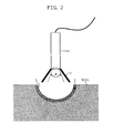
- Figure 2 is an enlarged view of the radiation thermometer 141 and the groove 1.
- a conical hood 3 diverging toward the groove 1 is mounted to the radiation thermometer 141 so as to surround the view angle ⁇ of the radiation thermometer 141.
- the opening area of the groove 1 is larger than the area of the region of the inner peripheral surface of the rotary blade 102d surrounded by an imaginary line as defined by this inner peripheral surface and the imaginary extension of the diverging leading edge of the hood 3 crossing each other. That is, the edge line of the opening of the groove 1 is situated outside the imaginary circle as defined by the imaginary extension and the inner peripheral surface crossing each other.
- the inner peripheral surface of the groove 1 and the inner side surface of the hood 3 are coated, as indicated at reference numeral 5, with a coating material having an emissivity higher than that of an aluminium alloy or nickel.
- the hood 3 is arranged so as to surround the view angle ⁇ of the radiation thermometer 141, so that radiation from the non-measurement range is blocked by the hood 3 and does not easily enter the interior of the hood 3. Further, since the edge line of the opening of the groove 1 is situated outside the above-mentioned imaginary crossing circle, radiation heat from a surface in the non-measurement range is reflected by the surface of the rotary blade 102d, and does not enter the sensor portion of the radiation thermometer 141.
- the groove 1 and the radiation thermometer 141 are arranged in the region between the stator column 122 and the rotary blade 102d, where the purge gas, which is a pure gas, passes. And, as compared with the portion of the base portion 129 in which the radiation thermometer 141 is embedded as shown in Figure 6, this region between the stator column 122 and the rotary blade 102d provides an environment relatively free from product deposition since the process gas does not pass therethrough directly. Thus, it is possible to prevent product deposition in the groove 1 leading to a change in the emissivity of the measurement object and to prevent product deposition in the optical system of the thermometer leading to a change in the measurement accuracy.
- the coating 5 of the inner peripheral surface of the groove 1 with a coating material having an emissivity higher than that of an aluminium alloy or nickel, the emissivity of the measurement object is higher than when there is no coating 5, whereby it is possible to improve the accuracy in the measurement of the temperature of the object.
- the coating 5 also on the inner side surface of the hood 3, radiation heat entering the hood is easily absorbed, and radiation heat from a non-measurement object is reflected to prevent it from entering the radiation thermometer 141, making it possible to improve the accuracy in the measurement of the temperature of the object.
- the groove 1 is not restricted to the peripheral one; it may also consist of a semispherical dent (in which case the section of the groove 1 is the same as that shown in Figure 2). Further, the section of the groove 1 is not restricted to the semicircular one; as shown in Figure 3, it may also be a rectangular one with a corner of R1 or more.
- hood 3 due to the provision of the hood 3, it is possible to reduce the probability of radiation heat from a non-measurement object entering the sensor portion of the radiation thermometer 141 as compared with the case in which there is no hood 3. Thus, it is possible to improve the accuracy in temperature measurement.
- the arrangement position for the groove 1 and the radiation thermometer 141 is not restricted to the region between the stator column 122 and the rotary blade 102d near the motor 121; it may also be position A or B encircled in Figure 1.
- the groove 1 and the radiation thermometer 141 are arranged between the stator column 122 and the rotary blade 102d near the upper radial electromagnet 104. In this case, they are arranged, as in the above-described case, in the region between the stator column 122 and the rotary blade 102d, where the purge gas, which is a pure gas, passes, and the region is less subject to product deposition, making it possible to further improve the accuracy in temperature measurement.
- the groove 1 and the radiation thermometer 141 are arranged in the region between the rotary blade 102d and the threaded spacer 131.
- the radiation thermometer 141 is embedded in the body portion of the threaded spacer 131, and the hood 3 can be arranged by utilizing the space of the thread grooves 131a of the threaded spacer 131.
- the groove 1 is circumferentially formed in the outer periphery of the rotary blade 102d.
- this region is at lower pressure and at higher temperature, so that it provides an environment less subject to product deposition.
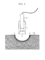
- Figure 5 is a schematic diagram showing the second embodiment of the present invention.
- the components which are the same as those of Figure 2 are indicated with the same reference numerals, and a description of such components will be omitted.
- a cylindrical hood 7 which is mounted to the outer peripheral wall portion of the cylinder of the radiation thermometer 141.
- the hood 7 has at its bottom an opening 7a, which is directed to the groove 1.
- the hood 7 is arranged so as not to intersect the view angle ⁇ of the radiation thermometer 141 and as to protrude by a predetermined length from the leading edge of the radiation thermometer 141.
- a hood is arranged so as to surround the view angle range of the radiation thermometer, whereby radiation heat from a non-measurement object is blocked by the hood and does not easily enter the interior of the hood, thereby making it possible to improve the accuracy in temperature measurement.
Landscapes
- Engineering & Computer Science (AREA)
- Physics & Mathematics (AREA)
- General Physics & Mathematics (AREA)
- Spectroscopy & Molecular Physics (AREA)
- Mechanical Engineering (AREA)
- General Engineering & Computer Science (AREA)
- Non-Positive Displacement Air Blowers (AREA)
- Radiation Pyrometers (AREA)
Abstract
Description
Claims (28)
- A radiation temperature measuring apparatus comprising:a radiation thermometer for measuring a temperature of a measurement object based on infrared rays constituting heat energy radiated from the measurement object; anda hood arranged so as not to interfere with a view angle range of the radiation thermometer and adapted to block radiation heat from a non-measurement object outside the view angle range.
- A turbo-molecular pump comprising a radiation temperature measuring apparatus as claimed in Claim 1.
- A radiation temperature measuring apparatus according to Claim 1, wherein an inner surface of the hood is coated with a coating material having an emissivity higher than that of an aluminium alloy or nickel.
- A turbo-molecular pump comprising a radiation temperature measuring apparatus as claimed in Claim 3.
- A radiation temperature measuring apparatus according to Claim 1, wherein the hood is formed in a conical configuration so as to surround the view angle range of the radiation thermometer and diverges toward the measurement object.
- A radiation temperature measuring apparatus according to Claim 1, wherein the hood is formed in a cylindrical configuration with an opening so as to surround the view angle range of the radiation thermometer, and wherein the opening is directed to the measurement object.
- A radiation temperature measuring apparatus comprising:a radiation thermometer for measuring a temperature of a measurement object based on infrared rays constituting heat energy radiated from the measurement object; anda groove in a semispherical configuration or with a semicircular section or a section with a corner of R1 or more formed in the measurement object so as to include a view diameter which is a range enclosed through crossing of a view angle range of the radiation thermometer and the measurement object.
- A turbo-molecular pump comprising a radiation temperature measuring apparatus as claimed in Claim 7.
- A turbo-molecular pump according to Claim 8, comprising:wherein the groove is formed in the rotary blade, and wherein the radiation thermometer is mounted to the stator column.a stator column containing an electrical component section including at least a motor;a rotation shaft extending through the stator column; anda rotary blade mounted to the rotation shaft and covering the periphery of the stator column,
- A turbo-molecular pump according to Claim 8, comprising:wherein the groove is formed in the rotary blade, and wherein the radiation thermometer is mounted to the spacer.a stator column containing an electrical component section including at least a motor;a rotation shaft extending through the stator column;a rotary blade mounted to the rotation shaft and covering the periphery of the stator column; anda spacer arranged in the outer periphery of the rotary blade,
- A radiation temperature measuring apparatus according to Claim 7, wherein a surface of the groove is coated with a coating material having an emissivity higher than that of an aluminium alloy or nickel.
- A turbo-molecular pump comprising a radiation temperature measuring apparatus as claimed in Claim 11.
- A turbo-molecular pump according to Claim 12, comprising:wherein the groove is formed in the rotary blade, and wherein the radiation thermometer is mounted to the stator column.a stator column containing an electrical component section including at least a motor;a rotation shaft extending through the stator column; anda rotary blade mounted to the rotation shaft and covering the periphery of the stator column,
- A turbo-molecular pump according to Claim 12, comprising:wherein the groove is formed in the rotary blade, and wherein the radiation thermometer is mounted to the spacer.a stator column containing an electrical component section including at least a motor;a rotation shaft extending through the stator column;a rotary blade mounted to the rotation shaft and covering the periphery of the stator column; anda spacer arranged in the outer periphery of the rotary blade,
- A radiation temperature measuring apparatus comprising:a radiation thermometer for measuring a temperature of a measurement object based on infrared rays constituting heat energy radiated from the measurement object;a hood arranged so as not to interfere with a view angle range of the radiation thermometer and adapted to block radiation heat radiated from a non-measurement object outside the view angle range; anda groove in a semispherical configuration or with a semicircular section or a section with a corner of R1 or more formed in the measurement object so as to include a range enclosed through crossing of an imaginary line defined by imaginarily extending an edge of the hood and the measurement object.
- A turbo-molecular pump comprising a radiation temperature measuring apparatus as claimed in Claim 15.
- A turbo-molecular pump according to Claim 16, comprising:wherein the groove is formed in the rotary blade, and wherein the radiation thermometer is mounted to the stator column.a stator column containing an electrical component section including at least a motor;a rotation shaft extending through the stator column; anda rotary blade mounted to the rotation shaft and covering the periphery of the stator column,
- A turbo-molecular pump according to Claim 16, comprising:wherein the groove is formed in the rotary blade, and wherein the radiation thermometer is mounted to the spacer.a stator column containing an electrical component section including at least a motor;a rotation shaft extending through the stator column;a rotary blade mounted to the rotation shaft and covering the periphery of the stator column; anda spacer arranged in the outer periphery of the rotary blade,
- A radiation temperature measuring apparatus according to Claim 15, wherein a surface of the groove is coated with a coating material having an emissivity higher than that of an aluminium alloy or nickel.
- A turbo-molecular pump comprising a radiation temperature measuring apparatus as claimed in Claim 19.
- A turbo-molecular pump according to Claim 20, further comprising:wherein the groove is formed in the rotary blade, and wherein the radiation thermometer is mounted to the stator column.a stator column containing an electrical component section including at least a motor;a rotation shaft extending through the stator column; anda rotary blade mounted to the rotation shaft and covering the periphery of the stator column,
- A turbo-molecular pump according to Claim 20, further comprising:wherein the groove is formed in the rotary blade, and wherein the radiation thermometer is mounted to the spacer.a stator column containing an electrical component section including at least a motor;a rotation shaft extending through the stator column;a rotary blade mounted to the rotation shaft and covering the periphery of the stator column; anda spacer arranged in the outer periphery of the rotary blade,
- A radiation temperature measuring apparatus according to Claim 15, wherein an inner surface of the hood is coated with a coating material having an emissivity higher than that of an aluminium alloy or nickel.
- A turbo-molecular pump comprising a radiation temperature measuring apparatus as claimed in Claim 23.
- A turbo-molecular pump according to Claim 24, further comprising:wherein the groove is formed in the rotary blade, and wherein the radiation thermometer is mounted to the stator column.a stator column containing an electrical component section including at least a motor;a rotation shaft extending through the stator column; anda rotary blade mounted to the rotation shaft and covering the periphery of the stator column,
- A turbo-molecular pump according to Claim 24, further comprising:wherein the groove is formed in the rotary blade, and wherein the radiation thermometer is mounted to the spacer.a stator column containing an electrical component section including at least a motor;a rotation shaft extending through the stator column;a rotary blade mounted to the rotation shaft and covering the periphery of the stator column; anda spacer arranged in the outer periphery of the rotary blade,
- A radiation temperature measuring apparatus according to Claim 15, wherein the hood is formed in a conical configuration so as to surround the view angle range of the radiation thermometer and diverges toward the groove.
- A radiation temperature measuring apparatus according to Claim 15, wherein the hood is formed in a cylindrical configuration with an opening so as to surround the view angle range of the radiation thermometer, and wherein the opening is directed to the groove.
Applications Claiming Priority (2)
| Application Number | Priority Date | Filing Date | Title |
|---|---|---|---|
| JP2002090299 | 2002-03-28 | ||
| JP2002090299A JP2003287463A (en) | 2002-03-28 | 2002-03-28 | Radiation-temperature measuring apparatus and turbo- molecular pump with the same mounted |
Publications (2)
| Publication Number | Publication Date |
|---|---|
| EP1348940A2 true EP1348940A2 (en) | 2003-10-01 |
| EP1348940A3 EP1348940A3 (en) | 2005-01-12 |
Family
ID=27800501
Family Applications (1)
| Application Number | Title | Priority Date | Filing Date |
|---|---|---|---|
| EP03251989A Withdrawn EP1348940A3 (en) | 2002-03-28 | 2003-03-28 | Radiation temperature measuring apparatus and turbo-molecular pump equipped with the same |
Country Status (3)
| Country | Link |
|---|---|
| US (1) | US6851848B2 (en) |
| EP (1) | EP1348940A3 (en) |
| JP (1) | JP2003287463A (en) |
Cited By (3)
| Publication number | Priority date | Publication date | Assignee | Title |
|---|---|---|---|---|
| DE102005057641A1 (en) * | 2005-12-02 | 2007-06-06 | Pfeiffer Vacuum Gmbh | Arrangement for non-contact temperature measurement on rotors |
| WO2010006631A1 (en) * | 2008-07-16 | 2010-01-21 | Siemens Aktiengesellschaft | System comprising an electric machine and method for operating an electric machine |
| US10837836B2 (en) | 2016-09-06 | 2020-11-17 | Edwards Limited | Temperature sensor for a high speed rotating machine |
Families Citing this family (17)
| Publication number | Priority date | Publication date | Assignee | Title |
|---|---|---|---|---|
| GB0502149D0 (en) | 2005-02-02 | 2005-03-09 | Boc Group Inc | Method of operating a pumping system |
| GB0508872D0 (en) * | 2005-04-29 | 2005-06-08 | Boc Group Plc | Method of operating a pumping system |
| JP4749054B2 (en) * | 2005-06-22 | 2011-08-17 | エドワーズ株式会社 | Turbomolecular pump and method of assembling turbomolecular pump |
| GB0607594D0 (en) * | 2006-04-13 | 2006-05-24 | Qinetiq Ltd | Computer security |
| JP2007294673A (en) * | 2006-04-25 | 2007-11-08 | Nikon Corp | Exposure equipment |
| US20090127323A1 (en) * | 2007-11-15 | 2009-05-21 | Bernhard Zeiler | Packaging machine and packages made therewith |
| JP5764283B2 (en) * | 2007-12-27 | 2015-08-19 | エドワーズ株式会社 | Vacuum pump |
| US20110200460A1 (en) * | 2008-08-19 | 2011-08-18 | Manabu Nonaka | Vacuum pump |
| US9267392B2 (en) * | 2010-10-19 | 2016-02-23 | Edwards Japan Limited | Vacuum pump |
| US9759233B2 (en) * | 2011-10-31 | 2017-09-12 | Edwards Japan Limited | Stator member and vacuum pump |
| JP6077804B2 (en) * | 2012-09-06 | 2017-02-08 | エドワーズ株式会社 | Fixed side member and vacuum pump |
| JP6414401B2 (en) * | 2014-07-08 | 2018-10-31 | 株式会社島津製作所 | Turbo molecular pump |
| JP7025844B2 (en) * | 2017-03-10 | 2022-02-25 | エドワーズ株式会社 | Vacuum pump exhaust system, vacuum pump installed in the vacuum pump exhaust system, purge gas supply device, temperature sensor unit, and vacuum pump exhaust method |
| EP3636933B1 (en) * | 2019-09-11 | 2021-11-03 | Pfeiffer Vacuum Gmbh | Method for determining a temperature using an infrared sensor |
| CN111780889B (en) * | 2020-06-09 | 2021-04-20 | 华中科技大学 | A method and system for synchronously measuring molecular rotation temperature and arrangement light intensity |
| FR3116310B1 (en) * | 2020-11-19 | 2023-03-17 | Pfeiffer Vacuum | Turbomolecular vacuum pump and method of manufacturing a rotor |
| EP4667763A1 (en) * | 2024-06-21 | 2025-12-24 | Agilent Technologies, Inc. | Bearing and rotary vacuum pump including such bearing |
Family Cites Families (15)
| Publication number | Priority date | Publication date | Assignee | Title |
|---|---|---|---|---|
| US3598136A (en) * | 1969-03-17 | 1971-08-10 | Avco Corp | Fluidic infrared sensing device |
| NL176323C (en) * | 1975-03-11 | 1985-03-18 | Philips Nv | SEMICONDUCTOR DEVICE FOR GENERATING INCOHERENT RADIATION. |
| JPS58218673A (en) * | 1982-06-15 | 1983-12-19 | Tokyo Electric Co Ltd | Infrared detection device for mobile objects |
| US4854730A (en) * | 1987-08-13 | 1989-08-08 | Jacob Fraden | Radiation thermometer and method for measuring temperature |
| US5277782A (en) * | 1991-12-13 | 1994-01-11 | Optical Radiation Corporation | Baffled cold shields for infrared detector |
| US5371369A (en) * | 1993-10-13 | 1994-12-06 | Litton Systems, Inc. | Conformal cold baffle for optical imaging systems |
| JP3125207B2 (en) * | 1995-07-07 | 2001-01-15 | 東京エレクトロン株式会社 | Vacuum processing equipment |
| US6214034B1 (en) * | 1996-09-04 | 2001-04-10 | Radiancy, Inc. | Method of selective photothermolysis |
| JP3057486B2 (en) * | 1997-01-22 | 2000-06-26 | セイコー精機株式会社 | Turbo molecular pump |
| US6206299B1 (en) * | 1998-04-17 | 2001-03-27 | Commercial Vehicle Systems, Inc. | Traction enhancing deployment system |
| WO2000058700A1 (en) * | 1999-03-30 | 2000-10-05 | Tokyo Electron Limited | Temperature measuring system |
| US6443616B1 (en) * | 1999-05-13 | 2002-09-03 | Gregory R. Brotz | Material melting point determination apparatus |
| JP4679683B2 (en) * | 1999-11-02 | 2011-04-27 | 株式会社日本触媒 | Method for producing water-absorbing polymer, and apparatus for producing the polymer |
| US6596995B1 (en) * | 2002-03-07 | 2003-07-22 | Manfred Bender | Remote sensing of molten metal properties |
| JP3669502B2 (en) * | 2002-06-25 | 2005-07-06 | 独立行政法人 宇宙航空研究開発機構 | Calibration method of total power microwave radiometer for artificial satellite |
-
2002
- 2002-03-28 JP JP2002090299A patent/JP2003287463A/en active Pending
-
2003
- 2003-03-24 US US10/395,673 patent/US6851848B2/en not_active Expired - Fee Related
- 2003-03-28 EP EP03251989A patent/EP1348940A3/en not_active Withdrawn
Cited By (4)
| Publication number | Priority date | Publication date | Assignee | Title |
|---|---|---|---|---|
| DE102005057641A1 (en) * | 2005-12-02 | 2007-06-06 | Pfeiffer Vacuum Gmbh | Arrangement for non-contact temperature measurement on rotors |
| DE102005057641B4 (en) * | 2005-12-02 | 2017-06-01 | Pfeiffer Vacuum Gmbh | Turbomolecular vacuum pump with non-contact rotor temperature measurement |
| WO2010006631A1 (en) * | 2008-07-16 | 2010-01-21 | Siemens Aktiengesellschaft | System comprising an electric machine and method for operating an electric machine |
| US10837836B2 (en) | 2016-09-06 | 2020-11-17 | Edwards Limited | Temperature sensor for a high speed rotating machine |
Also Published As
| Publication number | Publication date |
|---|---|
| US6851848B2 (en) | 2005-02-08 |
| JP2003287463A (en) | 2003-10-10 |
| US20030185272A1 (en) | 2003-10-02 |
| EP1348940A3 (en) | 2005-01-12 |
Similar Documents
| Publication | Publication Date | Title |
|---|---|---|
| US6851848B2 (en) | Turbo-molecular pump having radiation temperature apparatus | |
| EP2469096B1 (en) | Vacuum pump | |
| US12571382B2 (en) | Turbomolecular pump | |
| CN110366640A (en) | Vacuum pump exhaust system, vacuum pump equipped with vacuum pump exhaust system, purge gas supply device, temperature sensor unit, and vacuum pump exhaust method | |
| EP1344940A1 (en) | Vacuum pump | |
| EP4357618A1 (en) | Vacuum pump | |
| US20240117816A1 (en) | Vacuum pump | |
| EP3910201A1 (en) | Vacuum pump | |
| JP7764138B2 (en) | vacuum pump | |
| EP4202227A1 (en) | Vacuum pump, fixed blade, and spacer | |
| US12378967B2 (en) | Vacuum pump | |
| US20230383757A1 (en) | Vacuum pump and vacuum exhaust system using the vacuum pump | |
| JP7712252B2 (en) | Vacuum pump | |
| JP7787120B2 (en) | vacuum pump | |
| US20240410379A1 (en) | Vacuum pump, vacuum pump bearing protection structure, and vacuum pump rotating body | |
| JP7697983B2 (en) | Vacuum pump, control device and temperature rise time control method | |
| JP7778746B2 (en) | Vacuum pump and hermetic connector | |
| JP2006083924A (en) | Magnetic bearing control device | |
| US12253089B2 (en) | Vacuum pump | |
| WO2023106154A1 (en) | Vacuum pump and good thermal conductivity component | |
| EP4656883A1 (en) | Vacuum pump | |
| JP2023010410A (en) | Vacuum pump | |
| JP2003269368A (en) | Vacuum pump |
Legal Events
| Date | Code | Title | Description |
|---|---|---|---|
| PUAI | Public reference made under article 153(3) epc to a published international application that has entered the european phase |
Free format text: ORIGINAL CODE: 0009012 |
|
| AK | Designated contracting states |
Kind code of ref document: A2 Designated state(s): AT BE BG CH CY CZ DE DK EE ES FI FR GB GR HU IE IT LI LU MC NL PT RO SE SI SK TR |
|
| AX | Request for extension of the european patent |
Extension state: AL LT LV MK |
|
| PUAL | Search report despatched |
Free format text: ORIGINAL CODE: 0009013 |
|
| AK | Designated contracting states |
Kind code of ref document: A3 Designated state(s): AT BE BG CH CY CZ DE DK EE ES FI FR GB GR HU IE IT LI LU MC NL PT RO SE SI SK TR |
|
| AX | Request for extension of the european patent |
Extension state: AL LT LV MK |
|
| AKX | Designation fees paid | ||
| REG | Reference to a national code |
Ref country code: DE Ref legal event code: 8566 |
|
| STAA | Information on the status of an ep patent application or granted ep patent |
Free format text: STATUS: THE APPLICATION IS DEEMED TO BE WITHDRAWN |
|
| 18D | Application deemed to be withdrawn |
Effective date: 20050713 |