EP1792552B1 - Kinderhochstuhl - Google Patents
Kinderhochstuhl Download PDFInfo
- Publication number
- EP1792552B1 EP1792552B1 EP07103026A EP07103026A EP1792552B1 EP 1792552 B1 EP1792552 B1 EP 1792552B1 EP 07103026 A EP07103026 A EP 07103026A EP 07103026 A EP07103026 A EP 07103026A EP 1792552 B1 EP1792552 B1 EP 1792552B1
- Authority
- EP
- European Patent Office
- Prior art keywords
- child
- retaining
- foot
- high chair
- highchair
- Prior art date
- Legal status (The legal status is an assumption and is not a legal conclusion. Google has not performed a legal analysis and makes no representation as to the accuracy of the status listed.)
- Expired - Lifetime
Links
Images


Classifications
-
- A—HUMAN NECESSITIES
- A47—FURNITURE; DOMESTIC ARTICLES OR APPLIANCES; COFFEE MILLS; SPICE MILLS; SUCTION CLEANERS IN GENERAL
- A47D—FURNITURE SPECIALLY ADAPTED FOR CHILDREN
- A47D15/00—Accessories for children's furniture, e.g. safety belts or baby-bottle holders
- A47D15/005—Restraining devices, e.g. safety belts, contoured cushions or side bumpers
-
- A—HUMAN NECESSITIES
- A47—FURNITURE; DOMESTIC ARTICLES OR APPLIANCES; COFFEE MILLS; SPICE MILLS; SUCTION CLEANERS IN GENERAL
- A47D—FURNITURE SPECIALLY ADAPTED FOR CHILDREN
- A47D1/00—Children's chairs
- A47D1/002—Children's chairs adjustable
-
- A—HUMAN NECESSITIES
- A47—FURNITURE; DOMESTIC ARTICLES OR APPLIANCES; COFFEE MILLS; SPICE MILLS; SUCTION CLEANERS IN GENERAL
- A47D—FURNITURE SPECIALLY ADAPTED FOR CHILDREN
- A47D1/00—Children's chairs
- A47D1/002—Children's chairs adjustable
- A47D1/004—Children's chairs adjustable in height
-
- A—HUMAN NECESSITIES
- A47—FURNITURE; DOMESTIC ARTICLES OR APPLIANCES; COFFEE MILLS; SPICE MILLS; SUCTION CLEANERS IN GENERAL
- A47D—FURNITURE SPECIALLY ADAPTED FOR CHILDREN
- A47D15/00—Accessories for children's furniture, e.g. safety belts or baby-bottle holders
- A47D15/005—Restraining devices, e.g. safety belts, contoured cushions or side bumpers
- A47D15/006—Restraining devices, e.g. safety belts, contoured cushions or side bumpers in chairs
Definitions
- the invention relates to a highchair with anti-slip, consisting of the highchair-bearing feet that pick up a seat plate and a seat back on their tops.
- the US 4,819,988 discloses a high chair with a table and a bracket, which can be adjusted against a vertical strut, which is firmly attached to the table base.
- the US 2,669,285 relates to a highchair with a table that can be attached via plug arms on the frame of the highchair, the arcuate plug arms are inserted into tube openings, which are part of the chair frame.
- a highchair of the type mentioned is for example from the DE 203 15 348 U1 known.
- the slipping protection is provided in the form of a substantially vertically extending safety belt, which is in communication with a headband, the headband horizontally between mounting plates height adjustable fastened is.
- the headband can always be adjusted in height, a removal of the retaining clip with seat belt is only consuming possible after a permanent assembly.
- Object of the present invention is to provide a highchair, which allows for existing slipping safely in a simple way, the placement of the child in the highchair.
- the base is fixedly mounted on the seat plate and consists of a receiving portion and an insertable into the receiving portion plug-in portion, wherein the plug portion carries the headband.
- the plug-in section can preferably be removed from the receiving section together with the retaining clip or, conversely, inserted into the retaining clip.
- the headband is removed from the receiving section along with the male portion before the infant is placed on the chair. Subsequently, the headband is moved in the normal operating position in the reverse manner.
- Fig. 1 shows a partial perspective view of a highchair with a seat plate 1, which is fixed in a known manner to a pair of feet or two pairs of feet of a highchair.
- a holding foot 4 consists of a receiving portion 10 and a plug portion 11.
- the plug portion 11 carries a headband 8.
- a receiving portion 10 is preferably fixedly mounted on the seat plate 1 and is approximately vertical upward from the seat plate 1.
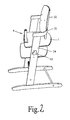
- Fig. 2 shows one Fig. 1 corresponding representation with deducted headband. 8
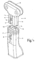
- Preferred embodiments of the holding foot 4 for the high chair after Fig. 1 and 2 are in the Figures 3 and 4 shown.
- the holding foot 4 has a receiving portion 10, which can be mounted on the seat plate 1 via a foot plate not shown.
- the receiving portion 10 includes a receiving opening 13, which serves to receive the plug-in portion 11.
- the opening 13 is formed by two chambers 13a, 13b.
- the plug portion 11 is composed of two subsections 11a and 11b, of which the portion 11b is inserted into the chamber 13b and the portion 11a is inserted into the chamber 13a.
- only one section or only one chamber may be provided in each case.
- the plug-in section 11 has latching teeth 15a, 15b which are each provided with tongues 16a, 16b.
- the tongues 16a, 16b are extended downward relative to the teeth 15a, 15b for the purpose to be described below.
- the receiving portion 10 has the teeth 15a, 15b associated openings 17a, 17b and the locking portions 18a, 18b. These Dearretianssabête 18 a, 18 b press when they are manually operated on the tongues 16 a, 16 b and then enter the Latching teeth 15a, 15b with respect to the openings or slots 17a, 17b free, whereby the plug portion 11 can be removed together with its headband 8 from the receiving portion 10.
- the chambers 13a, 13b are separated by a partition 20 and lie one behind the other or parallel one behind the other, viewed from the front side of the highchair. Accordingly, the subsections 11a, 11b are according to FIG Fig.
- the locking teeth 15a, 15b are introduced into the relevant chamber 13a, 13b due to beveled surfaces on their front side until the teeth 15a, 15b reach the openings 17a, 17b of the receiving portion 10 and by their elasticity to shift outwards, whereby the locking teeth 15a, 15b engage with the latching openings 17a, 17b. This has the consequence that the plug portion 11 is firmly seated in the receiving portion 10.
- the division in the form of the subsections 11a, 11b or chambers 13a, 13b serves to improve the stability of the base and the attachment between the receiving section and the plug section, for which purpose a partition wall 20 ultimately serves, with the inserted section 11 between the subsections 11a , 11b comes to rest.
- Fig. 4 shows one opposite Fig. 3 modified embodiment.
- the receiving portion 10 has two chambers 13a, 13b, compared to the embodiment according to FIG Fig. 3 rotated by 90 ° next to each other.
- the two chambers 13a, 13b define a third chamber 13c, which is thus provided centrally and exclusively serves to guide a locking tooth 15.
- the latching tooth 15 is also provided with a tongue 16 which projects downwardly from the latching tooth, such that the latching tooth can engage in a corresponding slot 17 of the receiving section.
- the plug-in section 11 with its sub-sections 11a, 11b is introduced into the respective chambers 13a, 13b of the receiving section 10, whereby, contrary to the embodiment according to FIG Fig. 3 a separate chamber 13c for receiving the latching mechanism in the form of the latching tooth 15 is provided.
- a separate chamber 13c for receiving the latching mechanism in the form of the latching tooth 15 is provided.
- the headband 8 is preferably inserted into a receiving slot 25 of the respective plug-in portion 11 and fastened by screwing or otherwise with respect to this. In this way it is possible to make the bracket 8 made of wood or other material and to conceal independently of the base 4.
- the in Fig. 1 and 2 The highchair shown further comprises a backrest 30, which can be attached to the foot section 34 by connecting parts 32, which are preferably made of plastic.
- the connecting parts 32 are provided with a hollow profile corresponding to the respective foot 34, as a result of which the backrest 30 together with the respective connecting part 32 can be placed on the foot pair 34 in a simple and fast manner.
- the seat plate 1 is adjustable in height, characterized in that the pair of feet 34 is provided on the inside with equal slits 36, respectively, for receiving and guide the support plate 1 serve.
- the feet 34 are held together and pulled together.
- the highchair according to the invention preferably consists of a single foot pair 34, between which the seat plate (1) is arranged.
- the backrest 30 is fastened by connecting elements 32, preferably made of plastic at the top of the foot pair 34.
- At the bottom of the pair of feet 34 are transverse to the pair of feet extending support legs, which are connected to each other in the illustrated embodiment via a single transverse web 38 ( Fig. 2 ).
- the backrest 32 can thus be placed on the foot pair 34 in a quick and simple manner and can optionally be fixedly connected to the foot pair 34 by cross-threading or another manner.
Landscapes
- Health & Medical Sciences (AREA)
- General Health & Medical Sciences (AREA)
- Pediatric Medicine (AREA)
- Buckles (AREA)
- Portable Outdoor Equipment (AREA)
- Organic Low-Molecular-Weight Compounds And Preparation Thereof (AREA)
- Seats For Vehicles (AREA)
Description
- Die Erfindung betrifft einen Kinderhochstuhl mit Durchrutschsicherung, bestehend aus den Kinderhochstuhl tragenden Füßen, die an ihren Oberseiten eine Sitzplatte und eine Sitzlehne aufnehmer.
- Aus der
US 5,806,922 ist ein Kinderhochstuhl mit Durchrutschsicherung bekannt, der aus den Kinderhochstuhl tragenden Füßen, die an ihrer Oberseite eine Sitzlehne aufnehmen, besteht, wobei die Durchrutschsicherung im Wesentlichen aus einem Bügel und einem Haltefuß besteht, der Haltefuß an der Sitzplatte angeordnet ist und der Bügel zusammen mit dem Haltefuß gegenüber der Sitzplatte entfernbar vorgesehen ist. - Die
US 4,819,988 offenbart einen Kinderhochstuhl mit einem Tisch und einem Haltebügel, welcher gegenüber einer Vertikalstrebe verstellt werden kann, die fest an der Tischunterfläche befestigt ist. - Aus der
US 2,552,720 ist ein Kinderhochstuhl bekannt, mit einem Tisch, der an seiner Unterseite eine Verstrebung aufweist, die zusammen mit dem Tisch gegenüber dem Tisch verstellbar ist, um eine Anpassung an den Umfang eines den Stuhl benutzenden Kindes zu ermöglichen. - Die
US 2,669,285 betrifft einen Kinderhochstuhl mit einem Tisch, der über Steckarme am Rahmen des Kinderhochstuhls befestigbar ist, wobei die bogenförmigen Steckarme in Rohröffnungen einzuschieben sind, welche Bestandteil des Stuhlrahmens sind. - Aus der
US 5,507,550 ist ein Kinderhochstuhl bekannt, der einen zwischen Armlehnen verstellbaren Tisch aufweist. - Ein Kinderhochstuhl der eingangs genannten Art ist beispielsweise aus der
DE 203 15 348 U1 bekannt. Bei diesem Kinderhochstuhl ist die Durchrutschsicherung in Form eines im Wesentlichen vertikal verlaufenden Sicherungsgurtes vorgesehen, der mit einem Haltebügel in Verbindung steht, wobei der Haltebügel horizontal zwischen Montageplatten höhenverstellbar befestigbar ist. Zwar lässt sich hierbei der Haltebügel grundsätzlich in seiner Höhe verstellen, ein Entfernen des Haltebügels mit Sicherheitsgurt ist jedoch nach einer Festmontage nur aufwendig möglich. - Aus der
DE 299 12 336 U1 ist ein zusammenklappbarer Kinderhochstuhl bekannt, bei dem ein Spieltisch als Durchrutschsicherung vorgesehen ist, der gegenüber einem Fußgestell umklappbar ist, jedoch wegen fehlendem Sicherungsgurt zwischen Spieltisch und Sitzplatte ein Durchrutschen des Kleinkindes nicht ausschließt. - Grundsätzlich besteht das Problem, dass bei Stühlen z. B. nach der
DE 203 15 348 bei fest vorgesehenem Haltebügel mit Sicherungsgurt die Füße des Kleinkindes vor dem Aufsetzen des Kleinkindes auf den Kinderhochstuhl durch die Durchrutschsicherung "hindurchgefädelt" werden müssen, was auch wegen der festmontierten Lehne meist auf Schwierigkeiten stößt und eine Gegenreaktion des Kleinkindes hervorruft oder zu Komplikationen oder Schmerzen führt, wenn die Beine des Kindes nicht richtig entlang der Durchrutschsicherung geführt werden. - Aufgabe vorliegender Erfindung ist es, einen Kinderhochstuhl zu schaffen, der bei vorhandener Durchrutschsicherung auf einfache Weise das Aufsetzen des Kindes in den Kinderhochstuhl ermöglicht.
- Diese Aufgabe wird erfindungsgemäß durch die im Patentanspruch 1 angegebenen Merkmale gelöst.
- Weitere Ausgestaltungen der Erfindung ergeben sich aus den Unteransprüchen.
- Der Standfuß ist fest auf der Sitzplatte montiert und besteht aus einem Aufnahmeabschnitt und einem in den Aufnahmeabschnitt hineinführbaren Steckabschnitt, wobei der Steckabschnitt den Haltebügel trägt. Durch eine Rast- und Freigabeeinrichtung lässt sich bei dieser Ausführungsform der Steckabschnitt aus dem Aufnahmeabschnitt vorzugsweise zusammen mit dem Haltebügel entfernen bzw. umgekehrt in den Haltebügel einsetzen.
- Der Haltebügel wird zusammen mit dem Steckabschnitt aus dem Aufnahmeabschnitt entfernt, bevor das Kleinkind auf den Stuhl gesetzt wird. Anschließend wird in umgekehrter Weise der Haltebügel in die normale Betriebsposition verbracht.
- Im Folgenden werden bevorzugte Ausführungsformen des erfindungsgemäßen Kinderhochstuhls anhand der Zeichnung zur Erläuterung weiterer Merkmale beschrieben. Es zeigen:
-
Fig. 1 eine Perspektivansicht einer Ausführungsform eines Kinderhochstuhls mit Durchrutschsicherung, wobei der Haltebügel in der ein Durchrutschen verhinderten Position dargestellt ist; -
Fig. 2 eineFig. 1 entsprechende Darstellung mit abgenommenen Haltebügel; -
Fig. 3 eine Darstellung einer bevorzugten Ausführungsform des den Bügel halternden Fußes, bestehend aus Aufnahmeabschnitt und Steckabschnitt, wobei der Haltebügel nicht dargestellt ist; -
Fig. 4 eineFig. 3 entsprechende Darstellung eines abgewandelten Fußes. - Nachfolgend wird eine bevorzugte Ausführungsform des erfindungsgemäßen Kinderhochstuhls beschrieben.
-
Fig. 1 zeigt eine perspektivische Teilansicht eines Kinderhochstuhls mit einer Sitzplatte 1, die in bekannter Weise an einem Fußpaar oder zwei Fußpaaren eines Kinderhochstuhls befestigt ist. - Bei dieser Ausführungsform besteht ein Haltefuß 4 aus einem Aufnahmeabschnitt 10 und einem Steckabschnitt 11. Der Steckabschnitt 11 trägt hierbei einen Haltebügel 8. Ein Aufnahmeabschnitt 10 ist vorzugsweise fest auf der Sitzplatte 1 montiert und steht von der Sitzplatte 1 etwa vertikal nach oben weg.
-
Fig. 2 zeigt eineFig. 1 entsprechende Darstellung mit abgezogenem Haltebügel 8. - Bevorzugte Ausführungsformen des Haltefußes 4 für den Kinderhochstuhl nach
Fig. 1 und2 sind in denFiguren 3 und4 dargestellt. - Gemäß
Fig. 3 weist der Haltefuß 4 einen Aufnahmeabschnitt 10 auf, der über eine nicht weiter dargestellte Fußplatte an der Sitzplatte 1 montiert sein kann. Der Aufnahmeabschnitt 10 enthält eine Aufnahmeöffnung 13, die zur Aufnahme des Steckabschnitts 11 dient. Bei der dargestellten Ausführungsform ist die Öffnung 13 durch zwei Kammern 13a, 13b gebildet. Der Steckabschnitt 11 besteht entsprechend aus zwei Unterabschnitten 11a und 11 b, von denen der Abschnitt 11b in die Kammer 13b und der Abschnitt 11a in die Kammer 13a eingeführt wird. Anstelle getrennter Kammern 13a, 13b und getrennter Unterabschnitte 11a können natürlich auch jeweils nur ein Abschnitt oder nur eine Kammer vorgesehen sein. - Der Steckabschnitt 11 weist bei dieser Ausführungsform Rastzähne 15a, 15b auf, die jeweils mit Zungen 16a, 16b versehen sind. Bei dieser Ausfiihrungsform sind die Zungen 16a, 16b gegenüber den Zähnen 15a, 15b nach unten verlängert zu dem noch nachfolgend beschriebenen Zweck.
- Der Aufnahmeabschnitt 10 weist den Zähnen 15a, 15b zugeordnete Öffnungen 17a, 17b auf sowie die der Arretierungsabschnitte 18a, 18b. Diese Dearretierungsabschnitte 18a, 18b drücken, wenn sie von Hand betätigt werden auf die Zungen 16a, 16b und geben dann die Rastzähne 15a, 15b gegenüber den Öffnungen oder Schlitzen 17a, 17b frei, wodurch der Steckabschnitt 11 zusammen mit seinem Haltebügel 8 aus dem Aufnahmeabschnitt 10 entfernt werden kann. Wie es aus den Darstellungen nach Fig. 5 entnehmbar ist, sind die Kammern 13a, 13b durch eine Trennwand 20 getrennt und liegen hintereinander bzw. parallel hintereinander, von der Vorderseite des Kinderhochstuhls her betrachtet. Entsprechend sind die Unterabschnitte 11a, 11b gemäß
Fig. 3 hintereinanderliegend ausgebildet, um unter Aufnahme der Trennwand 20 in den Aufnahmeabschnitt 10 eingeschoben werden zu können. Wird der Steckabschnitt 11 in den Aufnahmeabschnitt 10 verlagert, werden die Rastzähne 15a, 15b aufgrund an ihrer Vorderseite abgeschrägten Flächen in die betreffende Kammer 13a, 13b eingeführt, bis die Zähne 15a, 15b die Öffnungen 17a, 17b des Aufnahmeabschnitts 10 erreichen und durch ihre Elastizität sich nach außen verlagern, wodurch die Rastzähne 15a, 15b mit den Rastöffnungen 17a, 17b in Eingriff gelangen. Dies hat zur Folge, dass der Steckabschnitt 11 fest im Aufnahmeabschnitt 10 sitzt. - Bei der in
Fig. 3 dargestellten Ausführungsform dient die Zweiteilung in Form der Unterabschnitte 11a, 11b bzw. Kammern 13a, 13b dazu, die Stabilität des Standfußes und der Befestigung zwischen Aufnahmeabschnitt und Steckabschnitt zu verbessern, wozu letztendlich eine Trennwand 20 dient, die bei aufgesetztem Steckabschnitt 11 zwischen den Unterabschnitten 11a, 11b zu liegen kommt. -
Fig. 4 zeigt eine gegenüberFig. 3 abgewandelte Ausführungsform. Bei der Ausführungsform nachFig. 4 weist der Aufnahmeabschnitt 10 zwei Kammern 13a, 13b auf, die gegenüber der Ausführungsform nachFig. 3 um 90° gedreht nebeneinander liegen. Hierbei definieren die beiden Kammern 13a, 13b eine dritte Kammer 13c, die somit mittig vorgesehen ist und ausschließlich dazu dient, einen Rastzahn 15 zu führen. Bei der Ausführungsform nachFig. 4 ist der Rastzahn 15 ebenfalls mit einer Zunge 16 versehen, die vom Rastzahn nach unten absteht, derart, dass der Rastzahn in einen entsprechenden Schlitz 17 des Aufnahmeabschnitts eingreifen kann. Entsprechend der Ausführungsform nachFig. 3 wird auch bei dieser Variante der Steckabschnitt 11 mit seinen Unterabschnitten 11a, 11b in die betreffenden Kammern 13a, 13b des Aufnahmeabschnitts 10 eingeführt, wobei abweichend zu der Ausführungsform nachFig. 3 eine separate Kammer 13c zur Aufnahme des Rastmechanismus in Form des Rastzahnes 15 vorgesehen ist. Beim Einstecken des Steckabschnitts 11 wird der Rastzahn 15 aufgrund einer Schrägfläche 15e federnd nach innen in den Raum zwischen den Unterabschnitten 11a, 11b verlagert. Nach Einführung des Steckabschnitts 11 gelangt schließlich der Rastzahn 15 in die Öffnung bzw. den Schlitz 17 und springt nach außen, wodurch eine Arretierung gegenüber dem Aufnahmeabschnitt 10 erfolgt. EntsprechendFig. 3 ist ein Dearretierungsabschnitt 18 vorgesehen, der unterhalb des Schlitzes liegt und der im Beaufschlagungsfalle auf die Zunge 16 drückt und dadurch den Rastzahn 15 gegenüber dem Schlitz 17 freigibt, so dass der Steckabschnitt 11 aus dem Aufnahmeabschnitt 10 entfernt werden kann. - Zum Lösen des Steckabschnitts 11 gegenüber dem Aufnahmeabschnitt 10 wird bei den in
Fig. 3 und4 gezeigten Ausführungsformen ein elastisch am Aufnahmeabschnitt 10 jeweils vorgesehener Kopf 18a, 18b betätigt, wodurch die Rastzähne 15a, 15b bzw. 15 gegenüber dem jeweiligen Rastschlitz freigegeben werden und damit der Steckabschnitt 11 gegenüber dem Aufnahmeabschnitt 10 freigegeben wird. - Aus vorstehender Ausführung ergibt sich, dass das Aufsetzen des Haltebügels wie auch die Entnahme des Haltebügels gegenüber dem Aufnahmeabschnitt 10 auf einfache, schnelle und sichere Weise erfolgen kann.
- In den
Figuren 3 und4 ist der Steckabschnitt jeweils ohne Haltebügel 8 dargestellt. - Der Haltebügel 8 wird vorzugsweise in einen Aufnahmeschlitz 25 des betreffenden Steckabschnitts 11 eingesetzt und durch Verschraubung oder auf andere Weise gegenüber diesem befestigt. Auf diese Weise ist es möglich, den Bügel 8 aus Holz oder anderem Material zu gestalten und unabhängig vom Standfuß 4 zu verdecken.
- Der in
Fig. 1 und2 dargestellte Kinderhochstuhl weist weiterhin eine Lehne 30 auf, die durch Verbindungsteile 32, die vorzugsweise aus Kunststoff bestehen, gegenüber dem Fußabschnitt 34 befestigt werden kann. Zu diesem Zweck sind die Verbindungsteile 32 mit einem Hohlprofil versehen, das dem jeweilige Fuß 34 entspricht, in Folge dessen die Lehne 30 zusammen mit dem jeweiligen Verbindungsteil 32 auf einfache und schnelle Weise auf das Fußpaar 34 aufgesetzt werden kann. - Bei der dargestellten Ausfiihrungsform ist die Sitzplatte 1 höhenverstellbar, dadurch, dass das Fußpaar 34 innenseitig mit jeweils gleich hohen Schlitzen 36 versehen ist, die zur Aufnahme und Führung der Stützplatte 1 dienen. Durch ein Schraubgestänge 38 mit Schraubköpfen 40 werden die Füße 34 zusammengehalten und zusammengezogen.
- Wie vorstehende Beschreibung und die Zeichnungen zeigen, besteht der erfindungsgemäße Kinderhochstuhl vorzugsweise aus einem einzigen Fußpaar 34, zwischen welchen die Sitzplatte (1) angeordnet ist. Die Lehne 30 ist durch Verbindungselemente 32, vorzugsweise aus Kunststoff an der Oberseite des Fußpaares 34 befestigt. An der Unterseite des Fußpaares 34 befinden sich quer zum Fußpaar verlaufende Stützfüße, die bei der dargestellten Ausführungsform über einen einzigen Quersteg 38 miteinander verbunden sind (
Fig. 2 ). Mit den erfindungsgemäß vorgesehen bogenförmigen Verbindungselementen 32 lässt sich damit die Lehne 32auf schnelle und einfache Weise auf das Fußpaar 34 aufsetzen und kann gegebenenfalls durch Querverschraubung oder andere Weise fest mit dem Fußpaar 34 verbunden werden.
Claims (6)
- Kinderhochstuhl mit Durchrutschsicherung, bestehend aus den Kinderhochstuhl tragenden Füßen, die an ihrer Oberseite eine Sitzplatte (1) und eine Sitzlehne (30) aufnehmen,
wobei
die Durchrutschsicherung (4, 8) im Wesentlichen aus einem Bügel (8) und einem Haltefuß (4) besteht, der Haltefuß (4) an der Sitzplatte (1) angeordnet ist und der Bügel (8) zusammen mit dem Haltefuß (4) gegenüber der Sitzplatte (1) entfernbar vorgesehen ist;
dadurch gekennzeichnet,
dass der Haltefuß (4) aus einem Aufnahmeabschnitt (10) und einem Steckabschnitt (11) besteht, wobei der Steckabschnitt (11) den Haltebügel (8) aufnimmt;
dass der Aufnahmeabschnitt (10) Aufnahmekammern (13a, 13b, 13c) aufweist zur Aufnahme von Abschnitten (11a, 11b) des Steckabschnitts (11);
dass der Haltefuß (4) mit einer Rasteinrichtung (15a, 15b; 17a, 17b; 15, 17) versehen ist; und
dass der Haltefuß (4) eine Entriegelungseinrichtung (18a, 18b; 18) aufweist zur Freigabe des Steckabschnitts (11) vom Aufnahmeabschnitt (10). - Kinderhochstuhl nach Anspruch 1,
dadurch gekennzeichnet,
dass der Steckabschnitt (11) mindestens zwei Führungsabschnitte (11a, 11b) aufweist, die in entsprechende Aufnahmeabschnitte (13a, 13b) des Aufnahmeabschnitts (10) verrastbar einsetzbar sind. - Kinderhochstuhl nach wenigstens einem der vorangehenden Ansprüche,
dadurch gekennzeichnet,
dass der Haltebügel (8) etwa U-förmig ausgebildet und fest in den Haltefuß (4) einsetzbar ist. - Kinderhochstuhl nach Anspruch 3,
dadurch gekennzeichnet,
dass der Haltebügel (8) mit dem Haltefuß (4) zumindest teilweise fest verbunden ist. - Kinderhochstuhl nach wenigstens einem der vorangehenden Ansprüche,
dadurch gekennzeichnet,
dass die Lehne (30) und die Sitzplatte (1) an einem Fußpaar (34) angeordnet sind. - Kinderhochstuhl nach Anspruch 5,
dadurch gekennzeichnet,
dass die Lehne (30) fest mit bogenförmigen Verbindungsstegen (32) verbunden ist,
wobei die Verbindungsstege (32) an ihrem von der Lehne (30) abgewandten Ende auf das Fußpaar (34) aufgesteckt sind.
Applications Claiming Priority (2)
| Application Number | Priority Date | Filing Date | Title |
|---|---|---|---|
| DE102004033333A DE102004033333A1 (de) | 2004-07-09 | 2004-07-09 | Kinderhochstuhl |
| EP05011937A EP1614371B1 (de) | 2004-07-09 | 2005-06-02 | Kinderhochstuhl |
Related Parent Applications (1)
| Application Number | Title | Priority Date | Filing Date |
|---|---|---|---|
| EP05011937A Division EP1614371B1 (de) | 2004-07-09 | 2005-06-02 | Kinderhochstuhl |
Publications (2)
| Publication Number | Publication Date |
|---|---|
| EP1792552A1 EP1792552A1 (de) | 2007-06-06 |
| EP1792552B1 true EP1792552B1 (de) | 2009-08-12 |
Family
ID=34937181
Family Applications (2)
| Application Number | Title | Priority Date | Filing Date |
|---|---|---|---|
| EP05011937A Expired - Lifetime EP1614371B1 (de) | 2004-07-09 | 2005-06-02 | Kinderhochstuhl |
| EP07103026A Expired - Lifetime EP1792552B1 (de) | 2004-07-09 | 2005-06-02 | Kinderhochstuhl |
Family Applications Before (1)
| Application Number | Title | Priority Date | Filing Date |
|---|---|---|---|
| EP05011937A Expired - Lifetime EP1614371B1 (de) | 2004-07-09 | 2005-06-02 | Kinderhochstuhl |
Country Status (3)
| Country | Link |
|---|---|
| EP (2) | EP1614371B1 (de) |
| AT (2) | ATE439067T1 (de) |
| DE (3) | DE102004033333A1 (de) |
Cited By (1)
| Publication number | Priority date | Publication date | Assignee | Title |
|---|---|---|---|---|
| US12016469B2 (en) | 2021-08-22 | 2024-06-25 | Skip Hop, Inc. | Convertible child chair |
Families Citing this family (7)
| Publication number | Priority date | Publication date | Assignee | Title |
|---|---|---|---|---|
| NO20051629A (no) * | 2005-04-01 | 2006-08-28 | Stokke As | Festebrakett til en stol med to vanger og seteplate |
| WO2008022643A1 (en) * | 2006-08-24 | 2008-02-28 | Leanderform Aps | High chair |
| US8550556B2 (en) | 2010-03-17 | 2013-10-08 | Mattel, Inc. | Reconfigurable infant support structure |
| GB2489442B (en) * | 2011-03-25 | 2013-02-20 | Nuna Int Bv | Child seat having a restraining bar structure and method of operating the same |
| CN103239057A (zh) * | 2012-02-10 | 2013-08-14 | 巧儿宜股份有限公司 | 婴幼儿载具 |
| DE102013223128B4 (de) * | 2013-11-13 | 2016-10-20 | Abc Design Gmbh | Kinderhochstuhl |
| CN104706090B (zh) | 2013-12-11 | 2018-01-19 | 明门香港股份有限公司 | 卡合连接机构及儿童座椅组件 |
Family Cites Families (7)
| Publication number | Priority date | Publication date | Assignee | Title |
|---|---|---|---|---|
| US2562629A (en) * | 1947-05-26 | 1951-07-31 | Charles G Miles | Collapsible high chair |
| US2552720A (en) * | 1948-06-18 | 1951-05-15 | Arlington Chair Company | Safety device for high chair trays |
| US2669285A (en) * | 1951-02-28 | 1954-02-16 | Harold S Young | Combination high chair, ladder, and stool |
| US4819988A (en) * | 1987-07-01 | 1989-04-11 | Thomas Hellstrom | Restraining device for a chair |
| US5507550A (en) * | 1994-06-06 | 1996-04-16 | Hasbro, Inc. | Highchair |
| IL117219A0 (en) * | 1996-02-21 | 1996-06-18 | Litaf Ind 1994 Ltd | High chair |
| US5927805A (en) * | 1997-04-18 | 1999-07-27 | Koala Corporation | Stackable children's high-chair |
-
2004
- 2004-07-09 DE DE102004033333A patent/DE102004033333A1/de not_active Ceased
-
2005
- 2005-06-02 DE DE502005007901T patent/DE502005007901D1/de not_active Expired - Lifetime
- 2005-06-02 AT AT07103026T patent/ATE439067T1/de not_active IP Right Cessation
- 2005-06-02 EP EP05011937A patent/EP1614371B1/de not_active Expired - Lifetime
- 2005-06-02 EP EP07103026A patent/EP1792552B1/de not_active Expired - Lifetime
- 2005-06-02 AT AT05011937T patent/ATE369773T1/de active
- 2005-06-02 DE DE502005001217T patent/DE502005001217D1/de not_active Expired - Lifetime
Cited By (1)
| Publication number | Priority date | Publication date | Assignee | Title |
|---|---|---|---|---|
| US12016469B2 (en) | 2021-08-22 | 2024-06-25 | Skip Hop, Inc. | Convertible child chair |
Also Published As
| Publication number | Publication date |
|---|---|
| DE502005001217D1 (de) | 2007-09-27 |
| EP1792552A1 (de) | 2007-06-06 |
| DE102004033333A1 (de) | 2006-01-26 |
| DE502005007901D1 (de) | 2009-09-24 |
| ATE369773T1 (de) | 2007-09-15 |
| ATE439067T1 (de) | 2009-08-15 |
| EP1614371B1 (de) | 2007-08-15 |
| EP1614371A1 (de) | 2006-01-11 |
Similar Documents
| Publication | Publication Date | Title |
|---|---|---|
| EP0824880B1 (de) | Stapelbarer Reihenstuhl für eine Saalbestuhlung oder dergleichen | |
| DE102015122122B4 (de) | Konvertierbare Hochstuhlanordnung mit einer entfernbaren Ablage | |
| DE102007014995B4 (de) | Kinderhochstuhl | |
| DE19924218A1 (de) | Stuhl mit abnehmbarer Arbeitsfläche | |
| EP0264555A2 (de) | Stuhl, insbesondere Bürostuhl, mit höhenverstellbarer Rückenlehne | |
| DE9406826U1 (de) | Vorrichtung zur Reihenverbindung von Stühlen | |
| EP1792552A1 (de) | Kinderhochstuhl | |
| DE2419483A1 (de) | Sitzmoebel mit nackenstuetze | |
| EP3908158B1 (de) | Sitzmöbelchassis | |
| EP3664665A1 (de) | Sitzmöbel, insbesondere hochstuhl für kinder | |
| DE4423250C2 (de) | Höhenverstellbarer Stuhl | |
| DE19504542B4 (de) | Stuhl | |
| DE10133132A1 (de) | Armstütze für Stühle | |
| DE29620067U1 (de) | Kindersicherheitssitz | |
| DE4140638A1 (de) | Kindersicherheitssitz | |
| DE8804359U1 (de) | Haltungssitzkeil | |
| EP2053942A1 (de) | Stuhl | |
| DE2719858C3 (de) | Haltevorrichtung für den Rücksitzen von Kraftfahrzeugen zugeordnete Kopfstützen | |
| DE2427147C3 (de) | ||
| DE2936423C2 (de) | Kopfstütze für Kraftfahrzeugsitze | |
| DE4410397C1 (de) | Möbel | |
| DE8504882U1 (de) | Sicherheitssitz für Kinder in Kraftfahrzeugen | |
| WO2025061940A1 (de) | Sitzmöbel für kinder | |
| DE20013696U1 (de) | Polstermöbel | |
| CH170726A (de) | Bestuhlung für Säle. |
Legal Events
| Date | Code | Title | Description |
|---|---|---|---|
| PUAI | Public reference made under article 153(3) epc to a published international application that has entered the european phase |
Free format text: ORIGINAL CODE: 0009012 |
|
| AC | Divisional application: reference to earlier application |
Ref document number: 1614371 Country of ref document: EP Kind code of ref document: P |
|
| AK | Designated contracting states |
Kind code of ref document: A1 Designated state(s): AT BE BG CH CY CZ DE DK EE ES FI FR GB GR HU IE IS IT LI LT LU MC NL PL PT RO SE SI SK TR |
|
| 17P | Request for examination filed |
Effective date: 20070621 |
|
| RAP1 | Party data changed (applicant data changed or rights of an application transferred) |
Owner name: HEINRICH GEUTHER KINDERMOEBEL UND -GERAETE GMBH & |
|
| 17Q | First examination report despatched |
Effective date: 20070821 |
|
| AKX | Designation fees paid |
Designated state(s): AT BE BG CH CY CZ DE DK EE ES FI FR GB GR HU IE IS IT LI LT LU MC NL PL PT RO SE SI SK TR |
|
| GRAP | Despatch of communication of intention to grant a patent |
Free format text: ORIGINAL CODE: EPIDOSNIGR1 |
|
| GRAS | Grant fee paid |
Free format text: ORIGINAL CODE: EPIDOSNIGR3 |
|
| GRAA | (expected) grant |
Free format text: ORIGINAL CODE: 0009210 |
|
| AC | Divisional application: reference to earlier application |
Ref document number: 1614371 Country of ref document: EP Kind code of ref document: P |
|
| AK | Designated contracting states |
Kind code of ref document: B1 Designated state(s): AT BE BG CH CY CZ DE DK EE ES FI FR GB GR HU IE IS IT LI LT LU MC NL PL PT RO SE SI SK TR |
|
| REG | Reference to a national code |
Ref country code: GB Ref legal event code: FG4D Free format text: NOT ENGLISH |
|
| REG | Reference to a national code |
Ref country code: CH Ref legal event code: EP |
|
| REG | Reference to a national code |
Ref country code: IE Ref legal event code: FG4D |
|
| REF | Corresponds to: |
Ref document number: 502005007901 Country of ref document: DE Date of ref document: 20090924 Kind code of ref document: P |
|
| LTIE | Lt: invalidation of european patent or patent extension |
Effective date: 20090812 |
|
| PG25 | Lapsed in a contracting state [announced via postgrant information from national office to epo] |
Ref country code: IS Free format text: LAPSE BECAUSE OF FAILURE TO SUBMIT A TRANSLATION OF THE DESCRIPTION OR TO PAY THE FEE WITHIN THE PRESCRIBED TIME-LIMIT Effective date: 20091212 Ref country code: FI Free format text: LAPSE BECAUSE OF FAILURE TO SUBMIT A TRANSLATION OF THE DESCRIPTION OR TO PAY THE FEE WITHIN THE PRESCRIBED TIME-LIMIT Effective date: 20090812 Ref country code: ES Free format text: LAPSE BECAUSE OF FAILURE TO SUBMIT A TRANSLATION OF THE DESCRIPTION OR TO PAY THE FEE WITHIN THE PRESCRIBED TIME-LIMIT Effective date: 20091123 Ref country code: SE Free format text: LAPSE BECAUSE OF FAILURE TO SUBMIT A TRANSLATION OF THE DESCRIPTION OR TO PAY THE FEE WITHIN THE PRESCRIBED TIME-LIMIT Effective date: 20090812 Ref country code: LT Free format text: LAPSE BECAUSE OF FAILURE TO SUBMIT A TRANSLATION OF THE DESCRIPTION OR TO PAY THE FEE WITHIN THE PRESCRIBED TIME-LIMIT Effective date: 20090812 |
|
| NLV1 | Nl: lapsed or annulled due to failure to fulfill the requirements of art. 29p and 29m of the patents act | ||
| PG25 | Lapsed in a contracting state [announced via postgrant information from national office to epo] |
Ref country code: SI Free format text: LAPSE BECAUSE OF FAILURE TO SUBMIT A TRANSLATION OF THE DESCRIPTION OR TO PAY THE FEE WITHIN THE PRESCRIBED TIME-LIMIT Effective date: 20090812 Ref country code: PL Free format text: LAPSE BECAUSE OF FAILURE TO SUBMIT A TRANSLATION OF THE DESCRIPTION OR TO PAY THE FEE WITHIN THE PRESCRIBED TIME-LIMIT Effective date: 20090812 Ref country code: NL Free format text: LAPSE BECAUSE OF FAILURE TO SUBMIT A TRANSLATION OF THE DESCRIPTION OR TO PAY THE FEE WITHIN THE PRESCRIBED TIME-LIMIT Effective date: 20090812 |
|
| REG | Reference to a national code |
Ref country code: IE Ref legal event code: FD4D |
|
| PG25 | Lapsed in a contracting state [announced via postgrant information from national office to epo] |
Ref country code: BG Free format text: LAPSE BECAUSE OF FAILURE TO SUBMIT A TRANSLATION OF THE DESCRIPTION OR TO PAY THE FEE WITHIN THE PRESCRIBED TIME-LIMIT Effective date: 20091112 Ref country code: PT Free format text: LAPSE BECAUSE OF FAILURE TO SUBMIT A TRANSLATION OF THE DESCRIPTION OR TO PAY THE FEE WITHIN THE PRESCRIBED TIME-LIMIT Effective date: 20091212 |
|
| PG25 | Lapsed in a contracting state [announced via postgrant information from national office to epo] |
Ref country code: CZ Free format text: LAPSE BECAUSE OF FAILURE TO SUBMIT A TRANSLATION OF THE DESCRIPTION OR TO PAY THE FEE WITHIN THE PRESCRIBED TIME-LIMIT Effective date: 20090812 Ref country code: IE Free format text: LAPSE BECAUSE OF FAILURE TO SUBMIT A TRANSLATION OF THE DESCRIPTION OR TO PAY THE FEE WITHIN THE PRESCRIBED TIME-LIMIT Effective date: 20090812 Ref country code: RO Free format text: LAPSE BECAUSE OF FAILURE TO SUBMIT A TRANSLATION OF THE DESCRIPTION OR TO PAY THE FEE WITHIN THE PRESCRIBED TIME-LIMIT Effective date: 20090812 Ref country code: DK Free format text: LAPSE BECAUSE OF FAILURE TO SUBMIT A TRANSLATION OF THE DESCRIPTION OR TO PAY THE FEE WITHIN THE PRESCRIBED TIME-LIMIT Effective date: 20090812 Ref country code: EE Free format text: LAPSE BECAUSE OF FAILURE TO SUBMIT A TRANSLATION OF THE DESCRIPTION OR TO PAY THE FEE WITHIN THE PRESCRIBED TIME-LIMIT Effective date: 20090812 |
|
| PG25 | Lapsed in a contracting state [announced via postgrant information from national office to epo] |
Ref country code: SK Free format text: LAPSE BECAUSE OF FAILURE TO SUBMIT A TRANSLATION OF THE DESCRIPTION OR TO PAY THE FEE WITHIN THE PRESCRIBED TIME-LIMIT Effective date: 20090812 |
|
| PLBE | No opposition filed within time limit |
Free format text: ORIGINAL CODE: 0009261 |
|
| STAA | Information on the status of an ep patent application or granted ep patent |
Free format text: STATUS: NO OPPOSITION FILED WITHIN TIME LIMIT |
|
| 26N | No opposition filed |
Effective date: 20100517 |
|
| PG25 | Lapsed in a contracting state [announced via postgrant information from national office to epo] |
Ref country code: GR Free format text: LAPSE BECAUSE OF FAILURE TO SUBMIT A TRANSLATION OF THE DESCRIPTION OR TO PAY THE FEE WITHIN THE PRESCRIBED TIME-LIMIT Effective date: 20091113 |
|
| BERE | Be: lapsed |
Owner name: HEINRICH GEUTHER KINDERMOBEL UND -GERATE G.M.B.H. Effective date: 20100630 |
|
| PG25 | Lapsed in a contracting state [announced via postgrant information from national office to epo] |
Ref country code: MC Free format text: LAPSE BECAUSE OF NON-PAYMENT OF DUE FEES Effective date: 20100630 |
|
| REG | Reference to a national code |
Ref country code: CH Ref legal event code: PL |
|
| GBPC | Gb: european patent ceased through non-payment of renewal fee |
Effective date: 20100602 |
|
| PG25 | Lapsed in a contracting state [announced via postgrant information from national office to epo] |
Ref country code: IT Free format text: LAPSE BECAUSE OF FAILURE TO SUBMIT A TRANSLATION OF THE DESCRIPTION OR TO PAY THE FEE WITHIN THE PRESCRIBED TIME-LIMIT Effective date: 20090812 |
|
| PG25 | Lapsed in a contracting state [announced via postgrant information from national office to epo] |
Ref country code: LI Free format text: LAPSE BECAUSE OF NON-PAYMENT OF DUE FEES Effective date: 20100630 Ref country code: CH Free format text: LAPSE BECAUSE OF NON-PAYMENT OF DUE FEES Effective date: 20100630 |
|
| PG25 | Lapsed in a contracting state [announced via postgrant information from national office to epo] |
Ref country code: BE Free format text: LAPSE BECAUSE OF NON-PAYMENT OF DUE FEES Effective date: 20100630 |
|
| PG25 | Lapsed in a contracting state [announced via postgrant information from national office to epo] |
Ref country code: GB Free format text: LAPSE BECAUSE OF NON-PAYMENT OF DUE FEES Effective date: 20100602 |
|
| PG25 | Lapsed in a contracting state [announced via postgrant information from national office to epo] |
Ref country code: AT Free format text: LAPSE BECAUSE OF NON-PAYMENT OF DUE FEES Effective date: 20100602 |
|
| PG25 | Lapsed in a contracting state [announced via postgrant information from national office to epo] |
Ref country code: CY Free format text: LAPSE BECAUSE OF FAILURE TO SUBMIT A TRANSLATION OF THE DESCRIPTION OR TO PAY THE FEE WITHIN THE PRESCRIBED TIME-LIMIT Effective date: 20090812 |
|
| PG25 | Lapsed in a contracting state [announced via postgrant information from national office to epo] |
Ref country code: HU Free format text: LAPSE BECAUSE OF FAILURE TO SUBMIT A TRANSLATION OF THE DESCRIPTION OR TO PAY THE FEE WITHIN THE PRESCRIBED TIME-LIMIT Effective date: 20100213 Ref country code: LU Free format text: LAPSE BECAUSE OF NON-PAYMENT OF DUE FEES Effective date: 20100602 |
|
| PG25 | Lapsed in a contracting state [announced via postgrant information from national office to epo] |
Ref country code: TR Free format text: LAPSE BECAUSE OF FAILURE TO SUBMIT A TRANSLATION OF THE DESCRIPTION OR TO PAY THE FEE WITHIN THE PRESCRIBED TIME-LIMIT Effective date: 20090812 |
|
| PGFP | Annual fee paid to national office [announced via postgrant information from national office to epo] |
Ref country code: FR Payment date: 20130703 Year of fee payment: 9 |
|
| REG | Reference to a national code |
Ref country code: FR Ref legal event code: ST Effective date: 20150227 |
|
| PG25 | Lapsed in a contracting state [announced via postgrant information from national office to epo] |
Ref country code: FR Free format text: LAPSE BECAUSE OF NON-PAYMENT OF DUE FEES Effective date: 20140630 |
|
| PGFP | Annual fee paid to national office [announced via postgrant information from national office to epo] |
Ref country code: DE Payment date: 20160630 Year of fee payment: 12 |
|
| REG | Reference to a national code |
Ref country code: DE Ref legal event code: R119 Ref document number: 502005007901 Country of ref document: DE |
|
| PG25 | Lapsed in a contracting state [announced via postgrant information from national office to epo] |
Ref country code: DE Free format text: LAPSE BECAUSE OF NON-PAYMENT OF DUE FEES Effective date: 20180103 |