EP1786580B1 - Method of producing a microneedle or microimplant - Google Patents
Method of producing a microneedle or microimplant Download PDFInfo
- Publication number
- EP1786580B1 EP1786580B1 EP05771798A EP05771798A EP1786580B1 EP 1786580 B1 EP1786580 B1 EP 1786580B1 EP 05771798 A EP05771798 A EP 05771798A EP 05771798 A EP05771798 A EP 05771798A EP 1786580 B1 EP1786580 B1 EP 1786580B1
- Authority
- EP
- European Patent Office
- Prior art keywords
- substance
- solid
- needle
- droplet
- droplets
- Prior art date
- Legal status (The legal status is an assumption and is not a legal conclusion. Google has not performed a legal analysis and makes no representation as to the accuracy of the status listed.)
- Expired - Lifetime
Links
Images
Classifications
-
- B—PERFORMING OPERATIONS; TRANSPORTING
- B81—MICROSTRUCTURAL TECHNOLOGY
- B81C—PROCESSES OR APPARATUS SPECIALLY ADAPTED FOR THE MANUFACTURE OR TREATMENT OF MICROSTRUCTURAL DEVICES OR SYSTEMS
- B81C1/00—Manufacture or treatment of devices or systems in or on a substrate
- B81C1/00015—Manufacture or treatment of devices or systems in or on a substrate for manufacturing microsystems
- B81C1/00023—Manufacture or treatment of devices or systems in or on a substrate for manufacturing microsystems without movable or flexible elements
- B81C1/00111—Tips, pillars, i.e. raised structures
-
- A—HUMAN NECESSITIES
- A61—MEDICAL OR VETERINARY SCIENCE; HYGIENE
- A61M—DEVICES FOR INTRODUCING MEDIA INTO, OR ONTO, THE BODY; DEVICES FOR TRANSDUCING BODY MEDIA OR FOR TAKING MEDIA FROM THE BODY; DEVICES FOR PRODUCING OR ENDING SLEEP OR STUPOR
- A61M37/00—Other apparatus for introducing media into the body; Percutany, i.e. introducing medicines into the body by diffusion through the skin
- A61M37/0015—Other apparatus for introducing media into the body; Percutany, i.e. introducing medicines into the body by diffusion through the skin by using microneedles
-
- B—PERFORMING OPERATIONS; TRANSPORTING
- B29—WORKING OF PLASTICS; WORKING OF SUBSTANCES IN A PLASTIC STATE IN GENERAL
- B29C—SHAPING OR JOINING OF PLASTICS; SHAPING OF MATERIAL IN A PLASTIC STATE, NOT OTHERWISE PROVIDED FOR; AFTER-TREATMENT OF THE SHAPED PRODUCTS, e.g. REPAIRING
- B29C37/00—Component parts, details, accessories or auxiliary operations, not covered by group B29C33/00 or B29C35/00
- B29C37/0053—Moulding articles characterised by the shape of the surface, e.g. ribs, high polish
-
- B—PERFORMING OPERATIONS; TRANSPORTING
- B29—WORKING OF PLASTICS; WORKING OF SUBSTANCES IN A PLASTIC STATE IN GENERAL
- B29C—SHAPING OR JOINING OF PLASTICS; SHAPING OF MATERIAL IN A PLASTIC STATE, NOT OTHERWISE PROVIDED FOR; AFTER-TREATMENT OF THE SHAPED PRODUCTS, e.g. REPAIRING
- B29C64/00—Additive manufacturing, i.e. manufacturing of three-dimensional [3D] objects by additive deposition, additive agglomeration or additive layering, e.g. by 3D printing, stereolithography or selective laser sintering
- B29C64/10—Processes of additive manufacturing
- B29C64/106—Processes of additive manufacturing using only liquids or viscous materials, e.g. depositing a continuous bead of viscous material
- B29C64/124—Processes of additive manufacturing using only liquids or viscous materials, e.g. depositing a continuous bead of viscous material using layers of liquid which are selectively solidified
- B29C64/129—Processes of additive manufacturing using only liquids or viscous materials, e.g. depositing a continuous bead of viscous material using layers of liquid which are selectively solidified characterised by the energy source therefor, e.g. by global irradiation combined with a mask
- B29C64/135—Processes of additive manufacturing using only liquids or viscous materials, e.g. depositing a continuous bead of viscous material using layers of liquid which are selectively solidified characterised by the energy source therefor, e.g. by global irradiation combined with a mask the energy source being concentrated, e.g. scanning lasers or focused light sources
-
- A—HUMAN NECESSITIES
- A61—MEDICAL OR VETERINARY SCIENCE; HYGIENE
- A61M—DEVICES FOR INTRODUCING MEDIA INTO, OR ONTO, THE BODY; DEVICES FOR TRANSDUCING BODY MEDIA OR FOR TAKING MEDIA FROM THE BODY; DEVICES FOR PRODUCING OR ENDING SLEEP OR STUPOR
- A61M37/00—Other apparatus for introducing media into the body; Percutany, i.e. introducing medicines into the body by diffusion through the skin
- A61M37/0015—Other apparatus for introducing media into the body; Percutany, i.e. introducing medicines into the body by diffusion through the skin by using microneedles
- A61M2037/0053—Methods for producing microneedles
-
- B—PERFORMING OPERATIONS; TRANSPORTING
- B29—WORKING OF PLASTICS; WORKING OF SUBSTANCES IN A PLASTIC STATE IN GENERAL
- B29C—SHAPING OR JOINING OF PLASTICS; SHAPING OF MATERIAL IN A PLASTIC STATE, NOT OTHERWISE PROVIDED FOR; AFTER-TREATMENT OF THE SHAPED PRODUCTS, e.g. REPAIRING
- B29C35/00—Heating, cooling or curing, e.g. crosslinking or vulcanising; Apparatus therefor
- B29C35/02—Heating or curing, e.g. crosslinking or vulcanizing during moulding, e.g. in a mould
- B29C35/08—Heating or curing, e.g. crosslinking or vulcanizing during moulding, e.g. in a mould by wave energy or particle radiation
- B29C35/0805—Heating or curing, e.g. crosslinking or vulcanizing during moulding, e.g. in a mould by wave energy or particle radiation using electromagnetic radiation
- B29C2035/0827—Heating or curing, e.g. crosslinking or vulcanizing during moulding, e.g. in a mould by wave energy or particle radiation using electromagnetic radiation using UV radiation
-
- B—PERFORMING OPERATIONS; TRANSPORTING
- B29—WORKING OF PLASTICS; WORKING OF SUBSTANCES IN A PLASTIC STATE IN GENERAL
- B29L—INDEXING SCHEME ASSOCIATED WITH SUBCLASS B29C, RELATING TO PARTICULAR ARTICLES
- B29L2031/00—Other particular articles
- B29L2031/759—Needles
-
- B—PERFORMING OPERATIONS; TRANSPORTING
- B33—ADDITIVE MANUFACTURING TECHNOLOGY
- B33Y—ADDITIVE MANUFACTURING, i.e. MANUFACTURING OF THREE-DIMENSIONAL [3-D] OBJECTS BY ADDITIVE DEPOSITION, ADDITIVE AGGLOMERATION OR ADDITIVE LAYERING, e.g. BY 3-D PRINTING, STEREOLITHOGRAPHY OR SELECTIVE LASER SINTERING
- B33Y80/00—Products made by additive manufacturing
-
- B—PERFORMING OPERATIONS; TRANSPORTING
- B81—MICROSTRUCTURAL TECHNOLOGY
- B81B—MICROSTRUCTURAL DEVICES OR SYSTEMS, e.g. MICROMECHANICAL DEVICES
- B81B2201/00—Specific applications of microelectromechanical systems
- B81B2201/05—Microfluidics
- B81B2201/055—Microneedles
Definitions
- the present invention relates to a method of producing microneedles or microimplants, particularly but not exclusively for use in the pharmaceutical industry.
- Transdermal drug delivery is an important route for pharmaceutical actives, but the outer layer of skin, the 10-20 micrometer thick layer called the stratum corneum, is an effective barrier for many chemical entities. Hence, the number of pharmaceutically active materials that can penetrate into the body through the skin is very limited, and is defined by factors such as polarity, logP, and molecular size. At the same time, many drugs are being synthesized which are unsuitable for oral delivery (for example, due to instability in the gastrointestinal tract, or first pass liver metabolism). Hence, the skin is an attractive, if problematic, route for delivery of these drugs, as well as drugs that act in the skin, but perhaps have systemic side effects.
- US6558361 and WO2004/035105 disclose the use of photolithography to produce microneedles.
- US2002/0020688 discloses a process for making microneedles in accordance with the preamble of claim 1 which comprises the deposition of a layer of polymer which is allowed to sag over an array of pillars.
- WO2004/062899 discloses the formation of microneedles using a mould.
- Other needle and master fabrication methods include etching techniques, thermal oxidation of silicon, Liga, stereolithography, laser machining and laser ablation.
- Such methods are typically time consuming and require expensive facilities to fabricate microneedles. Moulding, for example, presents other problems, such as the quality of the microneedles being limited by the quality of the master and the lifetime of the mould. Furthermore, moulds present problems in the event that the needles are of a high aspect ratio; such moulds may be difficult to fill and may not be released readily from the microneedles formed by the mould. The present invention seeks to mitigate at least one or more of the problems of the prior art.
- the first surface is preferably a solid surface, but may be a non-solid surface.
- Step (i) may comprise depositing the substance in non-solid form.
- a non-solid substance may flow or be flowable.
- the substance in its non-solid form may, for example, be in the form of a liquid, gel, emulsion, cream, paste or thixotropic material. It should be noted that the substance in non-solid form may comprise solids, for example, in the form of particles. These particles may be suspended or dispersed in a carrier so that the bulk substance is non-solid.
- Step (i) may comprise depositing the substance in solid form. Such substances may not flow.
- An example of such a step may include the deposition of a solid substance by laser printing.
- the step of forming a solid from the substance may, for example, include exposure of the substance to ultraviolet radiation to form a solid polymer, loss of solvent to form a solid and curing over time (for example, when the non-solid substance comprises a two-part epoxy resin that, over time, cures to form a solid).
- the solid needle-like structure may not (and more probably, will not) have the same chemical composition as the non-solid substance.
- Step (ii) may comprise depositing a second portion or droplet of substance onto the first portion or droplet of substance. This allows a needle-like structure to be built-up by depositing one portion of substance upon another. It further allows fast production of needle-like structures using automatic liquid deposition technology.
- first portion or droplet is deposited in non-solid form, then it is preferred that the first portion or droplet is at least partially solidified prior to the deposition of the second or droplet of substance.
- Partially solidifying the first portion or droplet of substance may include exposing the first portion or droplet to electromagnetic radiation, for example, or merely waiting for a predetermined time period before depositing the second portion or droplet.
- One or both of the first and second portions of substance may be deposited in solid form. This would facilitate the production of microneedles using certain printing techniques, such as laser printing.
- volume of the second droplet or portion is smaller than the volume of the first droplet or portion. This facilitates the production of needle-like structures.
- Needle-like structures may be built-up by the sequential deposition of droplets or portions of substance on top of each other.
- Step (ii) may comprise sequential deposition of a plurality of portions or droplets of substance onto the first portion or droplet. If one or more of the portions or droplets is deposited in non-solid form, then it is preferred that the said one or more portion or droplet is at least partially solidified prior to the deposition of a further portion or droplet of substance thereon. If one or more of the portions or droplets is deposited in non-solid form, then it is preferred that each of the portions or droplets is deposited in non-solid form. This facilitates the production of needle-like shapes. In this case, it is preferred that the volume of the further portion or droplet is smaller than the volume of the immediately underlying portion or droplet at deposition of the immediately underlying portion or droplet.
- step (ii) may comprise providing a second surface that is in contact with the (preferably non-solid) substance and moving the first surface and the second surface relative to one another to form a needle-like shape.
- This drawing of needles is especially of benefit when the substance is in non-solid form. Drawing of needles is relatively simple to achieve and further lends itself to being a rapid and automated process.
- the method of the present invention may comprise depositing one or more portions of substance using the sequential deposition method as described above and then drawing a needle-like shape from the said substance.
- Step (i) may comprise providing a portion or droplet of non-solid substance on the second surface, and moving the second surface into proximity to the first surface so that the droplet or portion of non-solid substance contacts the first surface.
- Providing a portion or droplet of non-solid substance on the second surface may be achieved, for example, by providing the non-solid substance in a reservoir and contacting the second surface with the non-solid substance in the reservoir. This allows the second surface to pick-up the substance from a reservoir and deposit it onto the first surface prior to the drawing of the needle.
- the second surface may be associated with an aperture or bore through which the non-solid substance is passed so as to deposit the substance (possibly as a discrete portion or droplet) onto the second surface.
- step (i) may comprise depositing the non-solid substance onto the first surface in the absence of the second surface.
- the non-solid substance may be deposited in the form of a droplet or portion.
- step (i) may comprise bringing the second surface into proximity to the first surface and subsequently providing the non-solid substance on the first surface so as to form a contact between the non-solid substance and the second surface. This could be achieved by introducing the substance through an aperture provided in or proximate to the first surface or an aperture provided in or proximate to the second surface.
- the second surface may be provided by a solid or a liquid.
- step (ii) may comprise the sequential steps of (a) moving the first surface and the second surface relative to one another to form a needle-like shape and (b) forming a solid needle-like shape. Contact may be maintained between the substance and the second surface during the formation of the solid needle-like shape. Alternatively, the second surface may be removed from the substance after step (a) and prior to step (b).
- Step (ii) may comprise forming a solid needle-like shape while moving the first surface and the second surface relative to one another.
- the deposition of the substance may be achieved using a printing method, such as stencil based deposition, contact printing (for example pin transfer) and other printing methods such as gravure, offset, electronic printing including xerographic and laser printing, inkjet or bubble printing, flexography, magnetography, and direct charge deposition.
- a printing method such as stencil based deposition, contact printing (for example pin transfer) and other printing methods such as gravure, offset, electronic printing including xerographic and laser printing, inkjet or bubble printing, flexography, magnetography, and direct charge deposition.
- Such methods may conveniently be used to deposit a first portion or droplet of substance (in solid or non-solid form). They may conveniently be used to sequentially deposit a plurality of portions or droplets one upon another so as to form a needle-like shape.
- a portion or droplet is at least partially solidified prior to the deposition of a further portion or droplet of substance thereon.
- Step (i) may comprise providing a stencil comprising at least one aperture, and depositing the substance (preferably in non-solid form) through the at least one aperture onto the first surface.
- Depositing the substance (preferably in non-solid form) through the at least one aperture may be achieved by urging the substance into the at least one aperture (as opposed to allowing the substance to spontaneously pass through the at least one aperture). This may be achieved, for example, by depositing the substance on the stencil and wiping the substance across the stencil and across the at least one aperture.
- Step (ii) may comprise moving the stencil in relation to the first surface, thus forming a needle-like shape.
- the stencil is acting like the second surface referred to above.
- the needle-like shape may be solidified as described elsewhere hererin.
- step (ii) may comprise moving the stencil in relation to the first surface, approximating the first surface to a second surface so that the second surface contacts the substance, and moving the second surface in relation to the first surface so as to form a needle-like shape.
- Step (ii) may comprise providing a stencil comprising at least one aperture, and depositing a plurality of portions or droplets of substance in (preferably in non-solid form) through the at least one aperture of the stencil. If a portion or droplet is deposited in non-solid form, then it is preferred that said portion or droplet is at least partially solidified prior to the deposition of a further portion or droplet of substance thereon. This may be achieved, for example, by depositing substance in non-solid form on the stencil, wiping the substance over the at least one aperture, moving the stencil and the first surface away from one another, solidifying the substance, approximating the stencil to the first surface, and then wiping substance in non-solid form over the at least one aperture.
- the deposition of a portion or droplet of substance may be performed by one or more of ink-jet printing, screen printing or micropipetting. Such methods may conveniently be used to produce microneedles and arrays of micro-needles quickly.
- the deposition of the substance may be by an automated handling system.
- the automated handling system may employ one or more of piezo valves, solenoid valves, syringe pumps, microelectromechanical devices, or air or other gas displacement means. These represent convenient means of controlling the deposition of the substance, especially if the substance is to be deposited in portions or droplets.
- the deposition of the substance may be by microarrayer or another automated contact printing device. These represent convenient means of controlling the deposition of the substance, especially if the substance is to be deposited in portions or droplets.
- the first surface may be part of, or a precursor to, a transdermal patch.
- the solid, needle-like shape may comprise one or both of an organic or silicone polymer, including epoxy resins, acrylic polymers and silicone resins.
- the solid needle-like shape may comprise a metal, such as titanium.
- the solid needle-like shape may comprise a mixture of a metal and non-metals (such as silica).
- the needle may comprise silicon (for example, porous silicon), a ceramic or a mineral.
- the solid needle-like shape may comprise silica.
- UV curable plastics such as acrylates, urethane acrylates and bioresorbable or biodegradable materials such as polylactides.
- Combinations of any materials can be used to form the needle.
- the base of a needle could be made of acrylate polymers, with one or more different strata of other materials, such as polylactides, or materials with particular characteristics such as ease of breakage to allow the tip of a needle to remain in the organism.
- the method may comprise inserting an elongate former into the substance prior to solidification so as to form a groove or bore in the needle-like shape.
- a groove may be useful for delivering fluids through the needle into the subject or article into which the needle may be inserted.
- the solid needle-like shape may be porous.
- a porous needle may be formed, for example, by one or more of causing a gas to pass through the needle-like shape during its formation; by providing a substance that spontaneously forms a solid, needle-like shape having a porous structure; by providing the substance with a component that may be removed (by dissolution, combustion or otherwise) from the solid, needle-like shape and by providing a substance that, on formation of a solid, needle-like shape, forms a porous mesh of fibres.
- Such porosity may be useful for delivering fluids through the needle into the subject or article into which the needle may be inserted.
- the method may further comprise introducing a dopant into the substance in order for the dopant to be released from the resultant solid at a later time.
- Step (i) or (ii) may comprise deposition of a catalyst or other reaction promoter.
- a catalyst for curing the substance could be deposited first on to the first surface, and the substance in non-solid form deposited on top of the catalyst. The catalyst would start to cure the substance on contact.
- the needle-like shape may be wholly or partly biodegradable.
- the needle-like shape may be readily separable from the first surface. This may facilitate the transfer of the needle from the first surface to a further surface. It may be desirable for the needle-like shape to be readily detachable in use.
- the solid, needle-like shape may be readily breakable to yield a first portion associated with the first surface and a second, dissociated portion.
- the step of forming a solid needle-like shape from a non-solid substance may comprise one or more of cooling the substance, heating the substance, waiting for a given period or exposing the non-solid substance to electromagnetic radiation (typically ultraviolet radiation). Cooling the substance may cause the substance to spontaneously form a solid. Heating may drive-off solvent from the substance, therefore causing a solid needle-like shape to form. Exposing the substance to electromagnetic radiation may cause the formation of a solid, for example, in the event that the non-solid substance is in the form of a UV-curable resin or adhesive. Waiting for a given period may cause the formation of a solid if, for example, the substance in its non-solid form is a two-part epoxy resin.
- electromagnetic radiation typically ultraviolet radiation
- the needles may be about 10 microns to 3mm long, preferably greater than 100 microns long and more preferably less than 1mm long.
- the most preferred length is about 200 to 400microns. Such a length of projection minimizes the chance of a projection reaching the dermis which is provided with nerves which generate pain response.
- the preferred length may vary depending on the biological layer which is intended to be punctured by the projections. For example, mucosal layers may require projections of different length than the stratum corneum.
- the preferred length of the microneedle may depend on the anatomical site at which the microneedle is intended to be used because the thickness of the stratum cornuem may vary between different anatomical sites.
- the microneedle is capable of puncturing a biological barrier, most preferably the stratum corneum of a human or animal.
- the method is preferably a method for forming a device for the puncturing of a biological barrier.
- the first surface is preferably provided by a substrate that forms part of a transdermal patch.
- the first surface may be provided by paper, glass, plastic, an adhesive semipermeable dressing film, metal and the adhesive side of pressure sensitive adhesive tape.
- the solid, needle-like structure may include a pharmaceutically active material. This may be achieved by introducing the pharmaceutically active material into the liquid prior to solidification or after solidification.
- the first surface onto which the solid, needle-like shape of the present invention may be formed may be provided by pillars, protrusions or the like.
- the method of the present invention may therefore by used to make microneedles on existing, needle-like or protruding structures.
- the solid needle-like shape may be conical.
- the solid needle-like shape may be pyramidal (for example, having three or four sides that converge to a point).
- the solid, needle-like shape may be curved. This may be achieved, for example, by using the needle-drawing method mentioned above and by moving the first and second surfaces relative to one another so as to produce a curved shape.
- the solid, needle-like shape may be provided with a hook, for example, by using the needle-drawing method mentioned above and by moving the first and second surfaces relative to one another so as to produce a hooked shape.
- the method in accordance with the second aspect of the present invention preferably does not involve the use of a mould.
- Step (i) comprises depositing an array of first portions or droplets of substance onto a first surface.
- Step (i) may comprise deposition of a substance in non-solid or solid form.
- an array of droplets or portions may be achieved by the serial deposition of droplets or portions on the first surface.
- an array of droplets or portions corresponding to the array of microneedles may be deposited simultaneously on the first surface.
- Step (ii) may comprise depositing an array of second droplets or portions of substance onto the array of first droplets or portions of substance.
- An array of third portions or droplets may be deposited onto the array of second portions or droplets.
- an array of needle-like structures may be developed by the sequential deposition of droplets or portions of substance.
- the method used in relation to the array may incorporate those features described above in relation to the method of the first aspect of the present invention.
- the substance may be deposited in a non-solid form and step (ii) may comprise providing a second surface in contact with the substance and moving the first surface and the second surface relative to one another to form a needle-like shape.
- An array of needle-like structures may, therefore, be drawn from the substance as described above with reference to the first aspect of the present invention.
- This substance may be deposited as discrete portion or droplets.
- Step (ii) may comprise introducing an array of second surfaces into contact with the non-solid substance and drawing the substance into an array of needle-like shapes.
- the microneedle structures may be drawn from the array of droplets or portions by introducing a second surface into contact with the array of portions or droplets and drawing the array of droplets or portions into an array of needle-like shapes. This may be achieved using a single, substantially flat planar second surface.
- one or more second surfaces may be used to sequentially draw needle-like shapes from the substance (optionally deposited as droplets or portions), the one or more second surfaces being moved so that the array of needles may be produced.
- the method of the second aspect of the present invention may comprise those features described above with reference to the method of the first aspect of the present invention.
- a stencil may be used to provide an array, as described with reference to the first aspect of the present invention.
- a method of manufacturing microneedles or microimplants either singly or in arrays, using deposition of a liquid onto a solid surface with subsequent or concurrent curing or other solidification into a solid needle-like shape, without use of a mould.
- the method of the third aspect of the present invention may comprise those features described above with reference to the method of the first aspect of the present invention.
- a product resulting from the invention can be a device for application to a biological barrier, the device comprising a substrate provided with one or more microneedle made in accordance with the method of the first, second or third aspects of the present invention.
- the device may comprise a first surface onto which one or more microneedle have been deposited using a method in accordance with the first, second or third aspects of the present invention.
- the first surface may be flexible.
- the device may, for example, be a transdermal patch.
- the device may comprise a sensor, a pump, or drug delivery device.
- the device may be provided with a means for urging the one or more microneedle into a biological barrier.
- the device may comprise a drug-eluting stent.
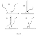
- a droplet 2 of liquid is dispensed onto a first surface 1 onto which it is intended to form microneedles.
- the droplet 2 is preferably dispensed by an automated liquid handling means.
- a second surface 3 for producing a needle-like shape is brought-up to the droplet 2, so the second surface 3 is touching the surface of the droplet 2.
- the second surface in this case is a solid surface, although a liquid surface could be used, for example a liquid surface formed by a liquid disposed on the end of a solid rod or needle.
- the second surface 3 is then moved away from first surface 1, drawing the liquid droplet 2 into a needle shape 4.
- the liquid is caused to cure or otherwise solidify into a microneedle 5 and the second surface 3 is then removed.
- the second surface 3 may be removed before curing or solidification has taken place, or even during the curing or solidification process. Removal of the second surface during curing or solidification may result in particularly sharp needles.
- the second surface 3 may be provided with the liquid and the liquid brought into contact with the first surface 1.
- the second surface 3 may be brought into proximity with the first surface 1 and the liquid dispensed so as to form contact with the first surface and the second surface. This may be affected by providing a bore associated with the second surface and dispensing the liquid through the bore.
- Relative movement of the first surface 1 and second surface 3 is important and therefore the position of the second surface 3 may be fixed, with the first surface 1 being moved in order to bring the second surface 3 into contact with the droplet 2.
- the needle-like shape may be solidified by cooling or by curing. This may be performed, for example, by using a curable liquid, such as a UV-curable acrylate adhesive, and by exposing the liquid to UV light to cure the adhesive.
- the liquid may be an epoxy resin.
- the first surface may be moved relative to the second surface to produce an elongate structure. This elongate structure is allowed to solidify over time. The elongate structure is then severed to allow the second surface to be removed from the first surface. This severing action causes the formation of a needle-like structure on the first surface.
- a spotting device such as a microarrayer may be used to place the liquid on a surface to act as a reservoir.
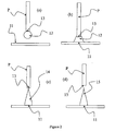
- a pin P of diameter 0.4mm was attached point downwards to a non-mobile support.
- a reservoir of non-solid substance from which the microneedle was to be made (in this case, a large spot of commercially available UV curing acrylate adhesive) was moved on a translation stage so that the head of the pin P was immersed in the substance for three seconds to produce a droplet of liquid 12 in contact with the end of the pin P.
- the solid surface 11 onto which the microneedle was to be formed was moved towards the second surface 13 (provided by the pin P) until the liquid 12 present on the end of the pin touched the solid surface 11.
- the solid surface 11 is allowed to touch the liquid-covered pin in such a way as to allow the liquid 12 to form a spot (see (b)).
- a UV source (a UV light emitting diode, not shown) supplies UV radiation to cure liquid 12.
- the solid surface 11 is moved away from the second surface 13 in a controlled manner using the translation stage to produce a needle-like shape 14 (see (c)).
- the finished needle 15 is left on the surface 1 (see (d)). This process produced a sharp needle structure of approximately 400 micrometres in height.
- Needles were produced using a variety of solid surfaces, including paper, glass, plastic, a transdermal drug delivery patch, an adhesive semipermeable dressing film, and the adhesive side of pressure sensitive adhesive tape.
- Use of pins of a larger diameter enabled the production of sharp needles of height over 1mm.
- Pins of a smaller diameter enabled production of structures of 250 ⁇ m in height.
- a third example of the method of the present invention is now described. Spots of a viscous epoxy resin were dispensed on a first glass surface using contact printing. The first glass surface was then placed on a stage moveable in the z direction. The first glass surface was approximated to a second, fixed glass surface, such that the drops of epoxy resin were touching the second glass surface. The first and second glass surfaces were slowly moved apart during curing of the resin, such that needle structures were drawn from each surface. After 3 hours, the resin had solidified, and any remaining connecting strands between the two surfaces were severed with scissors. The result was two glass surfaces with very sharp, hard microneedle structures projecting perpendicular to the surface. During curing, the tips of the needles were easy to bend, and could be deflected into curved, or even hooked structures. Loops could also be formed by pressing the flexible tips against the glass surface. These shapes persisted after curing was completed.
- the second surface may have a low surface area for contact with the liquid. This enables fine, needle-like structures to be produced.
- the second surface may be provided by the tip of a pointed object such as a pin, typically having a diameter of 0.4mm.
- the second surface may remain in needle-drawing contact with the liquid by virtue of the surface properties of the liquid and second surface. This may be achieved, for example, by using an adhesive as the liquid. Alternatively, the second surface may be held in contact with the liquid by use of a vacuum with the second surface. Alternatively, the second surface may be provided by a structure provided with a bore into which the liquid may flow by virtue of capillary action.
- the method may further comprise moving the first surface relative to the second surface prior to solidification or curing so as to form a needle structure that is one or more of curved or inclined relative to the first surface or hook-bearing.
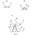
- a first portion 32 of non-solid substance in the form of a UV curable adhesive is deposited onto a first surface 31 using an automated liquid handling system (not shown) (see (a)).
- the substance is then cured or at least partially cured using a UV light source (not shown).
- a second portion 33 is then deposited onto the first portion 32 of substance, and is subsequently cured as previously described (see (b)).
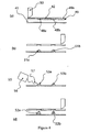
- a stencil 49 is brought into proximity to a first surface 41 (see figure 4a ).
- the first surface 41 is provided by the upper surface of a flexible substrate.
- the stencil 49 is provided with approximately 1000 apertures, each of 100 ⁇ m diameter, in a 1cm 2 area. Only two of the apertures, 48a and 48b, are shown here for clarity.
- This wiping action urged the acrylate 42 into the apertures 48a and 48b and urges stencil 49 into contact with the first surface 41.
- the acrylate 42 adheres to the first surface 41 so that when the stencil 49 is moved away from the first surface 41 (see Figures 4b ), portions 51a, 51b of acrylate remain on the first surface 41.
- the portions of acrylate 51a, 51b are then cured by exposure to UV radiation (shown schematically as 57) emitted from a UV "spot" source 56 ( Figure 4c ) to form solid structures 53a, 53b.
- the stencil 49 was replaced so that further portions of non-solid substance 42 could be deposited onto the existing structures 53a, 53b.
- Needle arrays produced by this method were shown to be capable of penetration of human stratum corneum in vitro.
- height of the needles can be increased to any size, and the tip diameter can be varied by changing variables such as material rheology, aperture size and squeegie speed or movement in the z axis.
- the sequential deposition technique described above with reference to Figures 3 and 4 may be combined with a needle-drawing methodology as described previously. Such techniques can also be used to produce needles of varied composition, for instance with one type of material forming a rod or other structure inside a needle of different composition.
- the internal structure may be formed from a porous material, or may be dissolvable to allow a pathway through the microneedle.
Landscapes
- Engineering & Computer Science (AREA)
- Health & Medical Sciences (AREA)
- Chemical & Material Sciences (AREA)
- Manufacturing & Machinery (AREA)
- Optics & Photonics (AREA)
- Materials Engineering (AREA)
- Physics & Mathematics (AREA)
- Anesthesiology (AREA)
- Life Sciences & Earth Sciences (AREA)
- Analytical Chemistry (AREA)
- Dermatology (AREA)
- Medical Informatics (AREA)
- Mechanical Engineering (AREA)
- Biomedical Technology (AREA)
- Heart & Thoracic Surgery (AREA)
- Hematology (AREA)
- Microelectronics & Electronic Packaging (AREA)
- Animal Behavior & Ethology (AREA)
- General Health & Medical Sciences (AREA)
- Public Health (AREA)
- Veterinary Medicine (AREA)
- Media Introduction/Drainage Providing Device (AREA)
- Organic Low-Molecular-Weight Compounds And Preparation Thereof (AREA)
- Polysaccharides And Polysaccharide Derivatives (AREA)
- Medicinal Preparation (AREA)
Priority Applications (2)
| Application Number | Priority Date | Filing Date | Title |
|---|---|---|---|
| EP10183463.8A EP2289646B1 (en) | 2004-08-16 | 2005-08-16 | Device to be applied to a biological barrier |
| EP10183472A EP2272430A1 (en) | 2004-08-16 | 2005-08-16 | Method of producing a microneedle or microimplant |
Applications Claiming Priority (3)
| Application Number | Priority Date | Filing Date | Title |
|---|---|---|---|
| GBGB0418246.5A GB0418246D0 (en) | 2004-08-16 | 2004-08-16 | Method for producing microneedles, microimplants and arrays thereof |
| GBGB0427762.0A GB0427762D0 (en) | 2004-12-17 | 2004-12-17 | Device and method for transport across barrier |
| PCT/GB2005/003224 WO2006018642A1 (en) | 2004-08-16 | 2005-08-16 | Method of producing a microneedle or microimplant |
Related Child Applications (3)
| Application Number | Title | Priority Date | Filing Date |
|---|---|---|---|
| EP10183463.8A Division EP2289646B1 (en) | 2004-08-16 | 2005-08-16 | Device to be applied to a biological barrier |
| EP10183463.8 Division-Into | 2010-09-30 | ||
| EP10183472.9 Division-Into | 2010-09-30 |
Publications (2)
| Publication Number | Publication Date |
|---|---|
| EP1786580A1 EP1786580A1 (en) | 2007-05-23 |
| EP1786580B1 true EP1786580B1 (en) | 2010-12-01 |
Family
ID=35447243
Family Applications (3)
| Application Number | Title | Priority Date | Filing Date |
|---|---|---|---|
| EP05771798A Expired - Lifetime EP1786580B1 (en) | 2004-08-16 | 2005-08-16 | Method of producing a microneedle or microimplant |
| EP10183472A Withdrawn EP2272430A1 (en) | 2004-08-16 | 2005-08-16 | Method of producing a microneedle or microimplant |
| EP10183463.8A Expired - Lifetime EP2289646B1 (en) | 2004-08-16 | 2005-08-16 | Device to be applied to a biological barrier |
Family Applications After (2)
| Application Number | Title | Priority Date | Filing Date |
|---|---|---|---|
| EP10183472A Withdrawn EP2272430A1 (en) | 2004-08-16 | 2005-08-16 | Method of producing a microneedle or microimplant |
| EP10183463.8A Expired - Lifetime EP2289646B1 (en) | 2004-08-16 | 2005-08-16 | Device to be applied to a biological barrier |
Country Status (7)
Families Citing this family (30)
| Publication number | Priority date | Publication date | Assignee | Title |
|---|---|---|---|---|
| US7699819B2 (en) | 2006-02-21 | 2010-04-20 | The Hong Kong University Of Science And Technology | Molecular sieve and zeolite microneedles and preparation thereof |
| CN100460028C (zh) * | 2006-12-08 | 2009-02-11 | 中国科学院上海微系统与信息技术研究所 | 一种用于药物传输的微针阵列及其制作方法 |
| US20100004608A1 (en) * | 2007-01-29 | 2010-01-07 | Medrx Co., Ltd. | Process for producing microneedle of thermosensitive substance |
| JP4959363B2 (ja) * | 2007-02-14 | 2012-06-20 | 凸版印刷株式会社 | 針状体の製造方法 |
| JP4978243B2 (ja) * | 2007-03-06 | 2012-07-18 | 凸版印刷株式会社 | 針状体および針状体製造方法 |
| WO2009021048A2 (en) * | 2007-08-06 | 2009-02-12 | Transderm, Inc. | Microneedle arrays formed from polymer films |
| KR20100037389A (ko) * | 2008-10-01 | 2010-04-09 | 연세대학교 산학협력단 | 다중 약물방출조절이 가능한 솔리드 마이크로구조체 및 이의 제조방법 |
| CN102238938A (zh) * | 2008-10-02 | 2011-11-09 | Nurim-Mwellness株式会社 | 制备固体微结构的方法和基于该方法制备的固体微结构 |
| JP2011005245A (ja) * | 2009-05-27 | 2011-01-13 | Kagawa Univ | 剣山型マイクロニードルの製造方法およびマイクロニードル |
| US8834423B2 (en) | 2009-10-23 | 2014-09-16 | University of Pittsburgh—of the Commonwealth System of Higher Education | Dissolvable microneedle arrays for transdermal delivery to human skin |
| KR101254240B1 (ko) * | 2010-12-17 | 2013-04-12 | 주식회사 라파스 | 마이크로구조체 제조방법 |
| KR101180032B1 (ko) | 2010-07-12 | 2012-09-05 | 인싸이토(주) | 외형 조절이 가능한 중공형 마이크로니들의 제조방법 |
| HK1209658A1 (en) | 2012-05-01 | 2016-04-08 | University Of Pittsburgh-Of The Commonwealth System Of Higher Education | Tip-loaded microneedle arrays for transdermal insertion |
| US10245436B2 (en) | 2012-07-17 | 2019-04-02 | Stimwave Technologies Incorporated | Miniature implantable device and methods |
| WO2014153228A1 (en) * | 2013-03-14 | 2014-09-25 | Perryman Laura Tyler | Miniature implantable device and methods |
| KR101488397B1 (ko) * | 2013-02-22 | 2015-02-03 | 연세대학교 산학협력단 | 음압을 이용한 마이크로구조체의 제조방법 및 그로부터 제조된 마이크로구조체 |
| US20160279401A1 (en) | 2015-03-27 | 2016-09-29 | Allergan, Inc. | Dissolvable microneedles for skin treatment |
| WO2016149673A1 (en) | 2015-03-18 | 2016-09-22 | University Of Pittsburgh - Of The Commonwealth System Of Higher Education | Bioactive components conjugated to substrates of microneedle arrays |
| JP2016195651A (ja) * | 2015-04-02 | 2016-11-24 | 日本写真印刷株式会社 | マイクロニードルシート |
| WO2017066768A1 (en) | 2015-10-16 | 2017-04-20 | University Of Pittsburgh-Of The Commonwealth System Of Higher Education | Mullti-component biio-active drug delivery and controlled release to the skin by microneedle array devices |
| WO2017120322A1 (en) | 2016-01-05 | 2017-07-13 | University Of Pittsburgh-Of The Commonwealth System Of Higher Education | Skin microenvironment targeted delivery for promoting immune and other responses |
| US11116954B2 (en) * | 2016-02-15 | 2021-09-14 | Shanghai Jiao Tong University | Method to print microneedle patches rapidly |
| KR101816922B1 (ko) * | 2016-05-20 | 2018-01-09 | 주식회사 라파스 | 마이크로니들 제조방법 |
| KR102408362B1 (ko) * | 2016-05-20 | 2022-06-13 | 주식회사 라파스 | 마이크로니들 제조방법 |
| KR102401856B1 (ko) | 2017-02-17 | 2022-05-26 | 알레간 인코포레이티드 | 활성 성분을 갖는 마이크로니들 어레이 |
| CN109420245A (zh) * | 2017-08-30 | 2019-03-05 | 优微(珠海)生物科技有限公司 | 可溶性微针的制造方法 |
| CN113874065A (zh) | 2019-05-16 | 2021-12-31 | 联邦高等教育系统匹兹堡大学 | 用于皮肤和非皮肤药物递送的具有底切特征的微针阵列 |
| GB2586474A (en) * | 2019-08-20 | 2021-02-24 | Innoture Ip Ltd | Method of manufacturing microstructures |
| GB2586475A (en) * | 2019-08-20 | 2021-02-24 | Innoture Ip Ltd | Methods |
| CN112618922A (zh) * | 2020-12-30 | 2021-04-09 | 上海心至医疗科技有限公司 | 一种药物球囊的制备方法、制备得到的药物球囊及其应用 |
Family Cites Families (54)
| Publication number | Priority date | Publication date | Assignee | Title |
|---|---|---|---|---|
| US3964482A (en) | 1971-05-17 | 1976-06-22 | Alza Corporation | Drug delivery device |
| JPS5428369A (en) | 1977-08-03 | 1979-03-02 | Yamakawa Tsuneko | Method of forming needleelike projection of thermoplastic resin on sheet |
| JPS6216132A (ja) * | 1985-07-12 | 1987-01-24 | Shimano & Co Ltd | 滑り止め突起を備えた釣竿の製造法 |
| US5309909A (en) * | 1992-05-22 | 1994-05-10 | Physio-Control Corporation | Combined skin preparation and monitoring electrode |
| US7422574B2 (en) | 1995-05-19 | 2008-09-09 | Applied Tissue Technologies, Llc | Microseeding device for gene delivery by microneedle injection |
| CA2330207C (en) | 1998-06-10 | 2005-08-30 | Georgia Tech Research Corporation | Microneedle devices and methods of manufacture and use thereof |
| US6689103B1 (en) | 1999-05-07 | 2004-02-10 | Scimed Life System, Inc. | Injection array apparatus and method |
| US6743211B1 (en) * | 1999-11-23 | 2004-06-01 | Georgia Tech Research Corporation | Devices and methods for enhanced microneedle penetration of biological barriers |
| ATE462468T1 (de) | 1999-06-04 | 2010-04-15 | Georgia Tech Res Inst | Vorrichtungen zur vergrösserten penetration von mikronadeln in biologischen hautschichten |
| US6312612B1 (en) * | 1999-06-09 | 2001-11-06 | The Procter & Gamble Company | Apparatus and method for manufacturing an intracutaneous microneedle array |
| US6379324B1 (en) | 1999-06-09 | 2002-04-30 | The Procter & Gamble Company | Intracutaneous microneedle array apparatus |
| US6623457B1 (en) | 1999-09-22 | 2003-09-23 | Becton, Dickinson And Company | Method and apparatus for the transdermal administration of a substance |
| US8465468B1 (en) | 2000-06-29 | 2013-06-18 | Becton, Dickinson And Company | Intradermal delivery of substances |
| US6511463B1 (en) | 1999-11-18 | 2003-01-28 | Jds Uniphase Corporation | Methods of fabricating microneedle arrays using sacrificial molds |
| US20010053891A1 (en) | 1999-12-30 | 2001-12-20 | Ackley Donald E. | Stacked microneedle systems |
| US6558361B1 (en) * | 2000-03-09 | 2003-05-06 | Nanopass Ltd. | Systems and methods for the transport of fluids through a biological barrier and production techniques for such systems |
| AU2001245472A1 (en) | 2000-03-09 | 2001-09-17 | Nanopass Ltd. | Systems and methods for the transport of fluids through a biological barrier andproduction techniques for such systems |
| WO2001091846A2 (en) | 2000-05-26 | 2001-12-06 | The Procter & Gamble Company | Microneedle apparatus used for marking skin and for dispensing semi-permanent subcutaneous makeup |
| US7473244B2 (en) | 2000-06-02 | 2009-01-06 | The University Of Utah Research Foundation | Active needle devices with integrated functionality |
| US6440096B1 (en) * | 2000-07-14 | 2002-08-27 | Becton, Dickinson And Co. | Microdevice and method of manufacturing a microdevice |
| AU8511601A (en) | 2000-08-21 | 2002-03-04 | Cleveland Clinic Foundation | Microneedle array module and method of fabricating the same |
| US6533949B1 (en) | 2000-08-28 | 2003-03-18 | Nanopass Ltd. | Microneedle structure and production method therefor |
| AU2001293460A1 (en) * | 2000-10-05 | 2002-04-15 | Thomas Marsoner | Medical injection device |
| WO2002045771A2 (en) | 2000-11-09 | 2002-06-13 | Biovalve Technologies, Inc. | Microneedle adapter |
| US9302903B2 (en) | 2000-12-14 | 2016-04-05 | Georgia Tech Research Corporation | Microneedle devices and production thereof |
| GB0030929D0 (en) | 2000-12-19 | 2001-01-31 | Inverness Medical Ltd | Analyte measurement |
| WO2002050584A2 (en) | 2000-12-21 | 2002-06-27 | Biovalve Technologies, Inc. | Microneedle array systems |
| US6663820B2 (en) | 2001-03-14 | 2003-12-16 | The Procter & Gamble Company | Method of manufacturing microneedle structures using soft lithography and photolithography |
| US6591124B2 (en) | 2001-05-11 | 2003-07-08 | The Procter & Gamble Company | Portable interstitial fluid monitoring system |
| US7127284B2 (en) | 2001-06-11 | 2006-10-24 | Mercator Medsystems, Inc. | Electroporation microneedle and methods for its use |
| US6767341B2 (en) | 2001-06-13 | 2004-07-27 | Abbott Laboratories | Microneedles for minimally invasive drug delivery |
| US6881203B2 (en) | 2001-09-05 | 2005-04-19 | 3M Innovative Properties Company | Microneedle arrays and methods of manufacturing the same |
| WO2003024507A2 (en) | 2001-09-19 | 2003-03-27 | Biovalve Technologies, Inc. | Microneedles, microneedle arrays, and systems and methods relating to same |
| CA2499838C (en) | 2001-09-21 | 2012-12-18 | Biovalve Technologies, Inc. | Gas pressure actuated microneedle arrays, and systems and methods relating to same |
| AU2002337788A1 (en) * | 2001-09-28 | 2003-04-07 | Biovalve Technologies, Inc. | Microneedle with membrane |
| WO2003026732A2 (en) | 2001-09-28 | 2003-04-03 | Biovalve Technologies, Inc. | Switchable microneedle arrays and systems and methods relating to same |
| US7429258B2 (en) | 2001-10-26 | 2008-09-30 | Massachusetts Institute Of Technology | Microneedle transport device |
| US6908453B2 (en) | 2002-01-15 | 2005-06-21 | 3M Innovative Properties Company | Microneedle devices and methods of manufacture |
| AU2003205315A1 (en) | 2002-01-22 | 2003-09-02 | Endobionics, Inc. | Methods and kits for delivering pharmaceutical agents into the coronary vascular adventitia |
| GB0201736D0 (en) | 2002-01-25 | 2002-03-13 | Glaxo Group Ltd | DNA dosage forms |
| US7004928B2 (en) | 2002-02-08 | 2006-02-28 | Rosedale Medical, Inc. | Autonomous, ambulatory analyte monitor or drug delivery device |
| JP4090018B2 (ja) * | 2002-02-18 | 2008-05-28 | For Head株式会社 | 機能性マイクロパイル及びその製造方法 |
| US7115108B2 (en) * | 2002-04-02 | 2006-10-03 | Becton, Dickinson And Company | Method and device for intradermally delivering a substance |
| US6780171B2 (en) * | 2002-04-02 | 2004-08-24 | Becton, Dickinson And Company | Intradermal delivery device |
| GB0216333D0 (en) | 2002-07-13 | 2002-08-21 | Univ Cranfield | Substance - selective polymer membranes |
| EP1523367A1 (en) | 2002-07-19 | 2005-04-20 | 3M Innovative Properties Company | Microneedle devices and microneedle delivery apparatus |
| US20040106894A1 (en) | 2002-09-06 | 2004-06-03 | Massachusetts Institute Of Technology | Needleless drug injection device |
| EP1590034B1 (en) | 2002-10-07 | 2014-05-14 | Biovalve Technologies, Inc. | Microneedle array patch |
| IL152271A (en) * | 2002-10-13 | 2006-04-10 | Meir Hefetz | Structures of micro needles and manufacturing methods |
| JP2006502831A (ja) * | 2002-10-13 | 2006-01-26 | ナノ パス テクノロジーズ リミテッド | 樹脂製のマイクロニードル |
| WO2004064889A2 (en) | 2003-01-16 | 2004-08-05 | Becton, Dickinson And Company | Intradermal cellular delivery using narrow gauge micro-cannula |
| KR100563330B1 (ko) | 2003-01-16 | 2006-03-22 | 포스트마이크로 주식회사 | Liga공정을 이용한 폴리머 재질의 미세 바늘 어레이제조방법 |
| AU2004244909A1 (en) * | 2003-06-10 | 2004-12-16 | Medrx Co., Ltd. | Process for producing pad base for transdermal drug administration, pad base for transdermal drug administration and needle |
| US7273474B2 (en) * | 2003-06-17 | 2007-09-25 | Industrial Technology Research Institute | Flexible substrate structure for microneedle arrays and its manufacturing method |
-
2005
- 2005-08-16 EP EP05771798A patent/EP1786580B1/en not_active Expired - Lifetime
- 2005-08-16 AT AT05771798T patent/ATE490037T1/de not_active IP Right Cessation
- 2005-08-16 US US11/660,341 patent/US8192787B2/en active Active
- 2005-08-16 JP JP2007526569A patent/JP5082053B2/ja not_active Expired - Fee Related
- 2005-08-16 EP EP10183472A patent/EP2272430A1/en not_active Withdrawn
- 2005-08-16 EP EP10183463.8A patent/EP2289646B1/en not_active Expired - Lifetime
- 2005-08-16 DE DE602005025138T patent/DE602005025138D1/de not_active Expired - Lifetime
- 2005-08-16 ES ES10183463.8T patent/ES2463818T3/es not_active Expired - Lifetime
- 2005-08-16 WO PCT/GB2005/003224 patent/WO2006018642A1/en active Application Filing
Also Published As
| Publication number | Publication date |
|---|---|
| JP2008509771A (ja) | 2008-04-03 |
| EP1786580A1 (en) | 2007-05-23 |
| DE602005025138D1 (de) | 2011-01-13 |
| JP5082053B2 (ja) | 2012-11-28 |
| WO2006018642A1 (en) | 2006-02-23 |
| EP2289646A1 (en) | 2011-03-02 |
| US8192787B2 (en) | 2012-06-05 |
| EP2272430A1 (en) | 2011-01-12 |
| ATE490037T1 (de) | 2010-12-15 |
| US20080299290A1 (en) | 2008-12-04 |
| EP2289646B1 (en) | 2014-02-12 |
| ES2463818T3 (es) | 2014-05-29 |
Similar Documents
| Publication | Publication Date | Title |
|---|---|---|
| EP1786580B1 (en) | Method of producing a microneedle or microimplant | |
| US10806914B2 (en) | Composite microneedle array including nanostructures thereon | |
| JP6005014B2 (ja) | 皮膚用針および皮膚用針を製造する方法 | |
| WO2007080427A2 (en) | Method of making microneedles | |
| EP2343101A1 (en) | Stamper for microneedle sheet, method for manufacturing the stamper, and method for manufacturing microneedle using the stamper | |
| WO2011043086A1 (ja) | マイクロニードルスタンパーの製造方法 | |
| JP6565906B2 (ja) | 針状体の製造方法、及び針状体 | |
| O'Mahony et al. | Accuracy and feasibility of piezoelectric inkjet coating technology for applications in microneedle-based transdermal delivery | |
| US10639822B2 (en) | Method of producing transdermal absorption sheet | |
| JP6525017B2 (ja) | マイクロニードルデバイス | |
| Sirbubalo et al. | Photopolymerization-based technologies for microneedle arrays production | |
| CN112839698B (zh) | 经皮吸收片材的制造方法 | |
| WO2020067102A1 (ja) | モールド、及び、経皮吸収シートの製造方法 | |
| EP2422836B1 (en) | Medication liquid supporting jig and method of applying medication to micro-needle using same | |
| ES2357079T3 (es) | Procedimiento de producción de un microaguja o un microimplante. | |
| JP4959151B2 (ja) | 皮膚用針の製造方法及び装置 | |
| JP5870551B2 (ja) | マイクロニードルデバイスの製造方法 | |
| KR20250055659A (ko) | 마이크로니들 패치 및 그 제조방법 | |
| JP2010142472A (ja) | 胴部に括れを有する突起部を具備する針状体およびその製造方法 |
Legal Events
| Date | Code | Title | Description |
|---|---|---|---|
| PUAI | Public reference made under article 153(3) epc to a published international application that has entered the european phase |
Free format text: ORIGINAL CODE: 0009012 |
|
| 17P | Request for examination filed |
Effective date: 20070315 |
|
| AK | Designated contracting states |
Kind code of ref document: A1 Designated state(s): AT BE BG CH CY CZ DE DK EE ES FI FR GB GR HU IE IS IT LI LT LU LV MC NL PL PT RO SE SI SK TR |
|
| RAP1 | Party data changed (applicant data changed or rights of an application transferred) |
Owner name: FUNCTIONAL MICROSTRUCTURES LIMITED |
|
| 17Q | First examination report despatched |
Effective date: 20071008 |
|
| DAX | Request for extension of the european patent (deleted) | ||
| GRAP | Despatch of communication of intention to grant a patent |
Free format text: ORIGINAL CODE: EPIDOSNIGR1 |
|
| GRAS | Grant fee paid |
Free format text: ORIGINAL CODE: EPIDOSNIGR3 |
|
| R17C | First examination report despatched (corrected) |
Effective date: 20071008 |
|
| GRAA | (expected) grant |
Free format text: ORIGINAL CODE: 0009210 |
|
| AK | Designated contracting states |
Kind code of ref document: B1 Designated state(s): AT BE BG CH CY CZ DE DK EE ES FI FR GB GR HU IE IS IT LI LT LU LV MC NL PL PT RO SE SI SK TR |
|
| REG | Reference to a national code |
Ref country code: GB Ref legal event code: FG4D |
|
| REG | Reference to a national code |
Ref country code: CH Ref legal event code: EP |
|
| REG | Reference to a national code |
Ref country code: IE Ref legal event code: FG4D |
|
| REF | Corresponds to: |
Ref document number: 602005025138 Country of ref document: DE Date of ref document: 20110113 Kind code of ref document: P |
|
| REG | Reference to a national code |
Ref country code: NL Ref legal event code: T3 |
|
| REG | Reference to a national code |
Ref country code: SE Ref legal event code: TRGR |
|
| RAP2 | Party data changed (patent owner data changed or rights of a patent transferred) |
Owner name: FUNCTIONAL MICROSTRUCTURES LIMITED |
|
| REG | Reference to a national code |
Ref country code: ES Ref legal event code: FG2A Ref document number: 2357079 Country of ref document: ES Kind code of ref document: T3 Effective date: 20110418 |
|
| PG25 | Lapsed in a contracting state [announced via postgrant information from national office to epo] |
Ref country code: LT Free format text: LAPSE BECAUSE OF FAILURE TO SUBMIT A TRANSLATION OF THE DESCRIPTION OR TO PAY THE FEE WITHIN THE PRESCRIBED TIME-LIMIT Effective date: 20101201 |
|
| REG | Reference to a national code |
Ref country code: GR Ref legal event code: EP Ref document number: 20110400525 Country of ref document: GR Effective date: 20110412 |
|
| LTIE | Lt: invalidation of european patent or patent extension |
Effective date: 20101201 |
|
| PG25 | Lapsed in a contracting state [announced via postgrant information from national office to epo] |
Ref country code: SI Free format text: LAPSE BECAUSE OF FAILURE TO SUBMIT A TRANSLATION OF THE DESCRIPTION OR TO PAY THE FEE WITHIN THE PRESCRIBED TIME-LIMIT Effective date: 20101201 Ref country code: AT Free format text: LAPSE BECAUSE OF FAILURE TO SUBMIT A TRANSLATION OF THE DESCRIPTION OR TO PAY THE FEE WITHIN THE PRESCRIBED TIME-LIMIT Effective date: 20101201 Ref country code: CY Free format text: LAPSE BECAUSE OF FAILURE TO SUBMIT A TRANSLATION OF THE DESCRIPTION OR TO PAY THE FEE WITHIN THE PRESCRIBED TIME-LIMIT Effective date: 20101201 Ref country code: LV Free format text: LAPSE BECAUSE OF FAILURE TO SUBMIT A TRANSLATION OF THE DESCRIPTION OR TO PAY THE FEE WITHIN THE PRESCRIBED TIME-LIMIT Effective date: 20101201 Ref country code: FI Free format text: LAPSE BECAUSE OF FAILURE TO SUBMIT A TRANSLATION OF THE DESCRIPTION OR TO PAY THE FEE WITHIN THE PRESCRIBED TIME-LIMIT Effective date: 20101201 Ref country code: BG Free format text: LAPSE BECAUSE OF FAILURE TO SUBMIT A TRANSLATION OF THE DESCRIPTION OR TO PAY THE FEE WITHIN THE PRESCRIBED TIME-LIMIT Effective date: 20110301 |
|
| PG25 | Lapsed in a contracting state [announced via postgrant information from national office to epo] |
Ref country code: PT Free format text: LAPSE BECAUSE OF FAILURE TO SUBMIT A TRANSLATION OF THE DESCRIPTION OR TO PAY THE FEE WITHIN THE PRESCRIBED TIME-LIMIT Effective date: 20110401 Ref country code: EE Free format text: LAPSE BECAUSE OF FAILURE TO SUBMIT A TRANSLATION OF THE DESCRIPTION OR TO PAY THE FEE WITHIN THE PRESCRIBED TIME-LIMIT Effective date: 20101201 Ref country code: BE Free format text: LAPSE BECAUSE OF FAILURE TO SUBMIT A TRANSLATION OF THE DESCRIPTION OR TO PAY THE FEE WITHIN THE PRESCRIBED TIME-LIMIT Effective date: 20101201 Ref country code: IS Free format text: LAPSE BECAUSE OF FAILURE TO SUBMIT A TRANSLATION OF THE DESCRIPTION OR TO PAY THE FEE WITHIN THE PRESCRIBED TIME-LIMIT Effective date: 20110401 Ref country code: CZ Free format text: LAPSE BECAUSE OF FAILURE TO SUBMIT A TRANSLATION OF THE DESCRIPTION OR TO PAY THE FEE WITHIN THE PRESCRIBED TIME-LIMIT Effective date: 20101201 |
|
| PG25 | Lapsed in a contracting state [announced via postgrant information from national office to epo] |
Ref country code: RO Free format text: LAPSE BECAUSE OF FAILURE TO SUBMIT A TRANSLATION OF THE DESCRIPTION OR TO PAY THE FEE WITHIN THE PRESCRIBED TIME-LIMIT Effective date: 20101201 Ref country code: PL Free format text: LAPSE BECAUSE OF FAILURE TO SUBMIT A TRANSLATION OF THE DESCRIPTION OR TO PAY THE FEE WITHIN THE PRESCRIBED TIME-LIMIT Effective date: 20101201 Ref country code: SK Free format text: LAPSE BECAUSE OF FAILURE TO SUBMIT A TRANSLATION OF THE DESCRIPTION OR TO PAY THE FEE WITHIN THE PRESCRIBED TIME-LIMIT Effective date: 20101201 |
|
| PLBE | No opposition filed within time limit |
Free format text: ORIGINAL CODE: 0009261 |
|
| STAA | Information on the status of an ep patent application or granted ep patent |
Free format text: STATUS: NO OPPOSITION FILED WITHIN TIME LIMIT |
|
| PG25 | Lapsed in a contracting state [announced via postgrant information from national office to epo] |
Ref country code: DK Free format text: LAPSE BECAUSE OF FAILURE TO SUBMIT A TRANSLATION OF THE DESCRIPTION OR TO PAY THE FEE WITHIN THE PRESCRIBED TIME-LIMIT Effective date: 20101201 |
|
| 26N | No opposition filed |
Effective date: 20110902 |
|
| REG | Reference to a national code |
Ref country code: DE Ref legal event code: R097 Ref document number: 602005025138 Country of ref document: DE Effective date: 20110902 |
|
| PG25 | Lapsed in a contracting state [announced via postgrant information from national office to epo] |
Ref country code: MC Free format text: LAPSE BECAUSE OF NON-PAYMENT OF DUE FEES Effective date: 20110831 |
|
| REG | Reference to a national code |
Ref country code: CH Ref legal event code: PL |
|
| PG25 | Lapsed in a contracting state [announced via postgrant information from national office to epo] |
Ref country code: LI Free format text: LAPSE BECAUSE OF NON-PAYMENT OF DUE FEES Effective date: 20110831 Ref country code: CH Free format text: LAPSE BECAUSE OF NON-PAYMENT OF DUE FEES Effective date: 20110831 |
|
| PG25 | Lapsed in a contracting state [announced via postgrant information from national office to epo] |
Ref country code: LU Free format text: LAPSE BECAUSE OF NON-PAYMENT OF DUE FEES Effective date: 20110816 |
|
| REG | Reference to a national code |
Ref country code: CH Ref legal event code: AERE Free format text: DAS PATENT IST AM 17.04.2013 GESTUETZT AUF DAS AM 31.08.2012 EINGEREICHTE WIEDEREINSETZUNGSGESUCH AUF GRUND VON ART. 47 PATG WIEDER IN KRAFT GESETZT WORDEN. |
|
| PGRI | Patent reinstated in contracting state [announced from national office to epo] |
Ref country code: LI Effective date: 20130417 Ref country code: CH Effective date: 20130417 |
|
| PG25 | Lapsed in a contracting state [announced via postgrant information from national office to epo] |
Ref country code: TR Free format text: LAPSE BECAUSE OF FAILURE TO SUBMIT A TRANSLATION OF THE DESCRIPTION OR TO PAY THE FEE WITHIN THE PRESCRIBED TIME-LIMIT Effective date: 20101201 |
|
| PG25 | Lapsed in a contracting state [announced via postgrant information from national office to epo] |
Ref country code: HU Free format text: LAPSE BECAUSE OF FAILURE TO SUBMIT A TRANSLATION OF THE DESCRIPTION OR TO PAY THE FEE WITHIN THE PRESCRIBED TIME-LIMIT Effective date: 20101201 |
|
| REG | Reference to a national code |
Ref country code: FR Ref legal event code: PLFP Year of fee payment: 11 |
|
| REG | Reference to a national code |
Ref country code: FR Ref legal event code: PLFP Year of fee payment: 12 |
|
| REG | Reference to a national code |
Ref country code: DE Ref legal event code: R082 Ref document number: 602005025138 Country of ref document: DE Representative=s name: SCHMITT-NILSON SCHRAUD WAIBEL WOHLFROM PATENTA, DE |
|
| REG | Reference to a national code |
Ref country code: FR Ref legal event code: PLFP Year of fee payment: 13 |
|
| REG | Reference to a national code |
Ref country code: FR Ref legal event code: PLFP Year of fee payment: 14 |
|
| REG | Reference to a national code |
Ref country code: DE Ref legal event code: R409 Ref document number: 602005025138 Country of ref document: DE Ref country code: DE Ref legal event code: R119 Ref document number: 602005025138 Country of ref document: DE |
|
| PGFP | Annual fee paid to national office [announced via postgrant information from national office to epo] |
Ref country code: GR Payment date: 20240229 Year of fee payment: 19 |
|
| PGFP | Annual fee paid to national office [announced via postgrant information from national office to epo] |
Ref country code: NL Payment date: 20240223 Year of fee payment: 19 Ref country code: ES Payment date: 20240227 Year of fee payment: 19 Ref country code: IE Payment date: 20240229 Year of fee payment: 19 |
|
| PGFP | Annual fee paid to national office [announced via postgrant information from national office to epo] |
Ref country code: DE Payment date: 20240229 Year of fee payment: 19 Ref country code: CH Payment date: 20240304 Year of fee payment: 19 Ref country code: GB Payment date: 20240221 Year of fee payment: 19 |
|
| PGFP | Annual fee paid to national office [announced via postgrant information from national office to epo] |
Ref country code: SE Payment date: 20240227 Year of fee payment: 19 Ref country code: IT Payment date: 20240216 Year of fee payment: 19 Ref country code: FR Payment date: 20240227 Year of fee payment: 19 |
|
| REG | Reference to a national code |
Ref country code: DE Ref legal event code: R119 Ref document number: 602005025138 Country of ref document: DE |
|
| REG | Reference to a national code |
Ref country code: CH Ref legal event code: PL |
|
| REG | Reference to a national code |
Ref country code: SE Ref legal event code: EUG |
|
| REG | Reference to a national code |
Ref country code: NL Ref legal event code: MM Effective date: 20240901 |
|
| GBPC | Gb: european patent ceased through non-payment of renewal fee |
Effective date: 20240816 |
|
| PG25 | Lapsed in a contracting state [announced via postgrant information from national office to epo] |
Ref country code: CH Free format text: LAPSE BECAUSE OF NON-PAYMENT OF DUE FEES Effective date: 20240831 Ref country code: GR Free format text: LAPSE BECAUSE OF NON-PAYMENT OF DUE FEES Effective date: 20250306 |
|
| PG25 | Lapsed in a contracting state [announced via postgrant information from national office to epo] |
Ref country code: NL Free format text: LAPSE BECAUSE OF NON-PAYMENT OF DUE FEES Effective date: 20240901 |
|
| PG25 | Lapsed in a contracting state [announced via postgrant information from national office to epo] |
Ref country code: DE Free format text: LAPSE BECAUSE OF NON-PAYMENT OF DUE FEES Effective date: 20250301 |
|
| PG25 | Lapsed in a contracting state [announced via postgrant information from national office to epo] |
Ref country code: GB Free format text: LAPSE BECAUSE OF NON-PAYMENT OF DUE FEES Effective date: 20240816 |
|
| PG25 | Lapsed in a contracting state [announced via postgrant information from national office to epo] |
Ref country code: IT Free format text: LAPSE BECAUSE OF NON-PAYMENT OF DUE FEES Effective date: 20240816 |
|
| PG25 | Lapsed in a contracting state [announced via postgrant information from national office to epo] |
Ref country code: FR Free format text: LAPSE BECAUSE OF NON-PAYMENT OF DUE FEES Effective date: 20240831 |
|
| PG25 | Lapsed in a contracting state [announced via postgrant information from national office to epo] |
Ref country code: IE Free format text: LAPSE BECAUSE OF NON-PAYMENT OF DUE FEES Effective date: 20240816 |