EP1785796A1 - Konstantgeschwindigkeits-universalverbindung und qualitätskontrollverfahren dafür - Google Patents
Konstantgeschwindigkeits-universalverbindung und qualitätskontrollverfahren dafür Download PDFInfo
- Publication number
- EP1785796A1 EP1785796A1 EP05766282A EP05766282A EP1785796A1 EP 1785796 A1 EP1785796 A1 EP 1785796A1 EP 05766282 A EP05766282 A EP 05766282A EP 05766282 A EP05766282 A EP 05766282A EP 1785796 A1 EP1785796 A1 EP 1785796A1
- Authority
- EP
- European Patent Office
- Prior art keywords
- constant velocity
- velocity universal
- universal joint
- tag
- information
- Prior art date
- Legal status (The legal status is an assumption and is not a legal conclusion. Google has not performed a legal analysis and makes no representation as to the accuracy of the status listed.)
- Withdrawn
Links
- 238000003908 quality control method Methods 0.000 title claims abstract description 85
- 238000004519 manufacturing process Methods 0.000 claims abstract description 236
- 239000000463 material Substances 0.000 claims description 114
- 238000005242 forging Methods 0.000 claims description 104
- 238000000227 grinding Methods 0.000 claims description 93
- 238000010438 heat treatment Methods 0.000 claims description 93
- 238000000034 method Methods 0.000 claims description 83
- 238000012545 processing Methods 0.000 claims description 49
- 238000007514 turning Methods 0.000 claims description 43
- 238000004891 communication Methods 0.000 claims description 29
- 238000012790 confirmation Methods 0.000 claims description 26
- 230000008569 process Effects 0.000 claims description 24
- 239000004519 grease Substances 0.000 claims description 13
- 238000005096 rolling process Methods 0.000 claims description 8
- 238000011144 upstream manufacturing Methods 0.000 claims description 5
- 229920003002 synthetic resin Polymers 0.000 claims description 4
- 239000000057 synthetic resin Substances 0.000 claims description 4
- 238000003860 storage Methods 0.000 description 20
- 238000010586 diagram Methods 0.000 description 18
- 238000005452 bending Methods 0.000 description 13
- 230000033001 locomotion Effects 0.000 description 10
- 230000008878 coupling Effects 0.000 description 8
- 238000010168 coupling process Methods 0.000 description 8
- 238000005859 coupling reaction Methods 0.000 description 8
- 238000012423 maintenance Methods 0.000 description 8
- 239000002184 metal Substances 0.000 description 8
- 229910052751 metal Inorganic materials 0.000 description 8
- 238000009826 distribution Methods 0.000 description 7
- 230000002093 peripheral effect Effects 0.000 description 7
- 230000000007 visual effect Effects 0.000 description 7
- 230000015572 biosynthetic process Effects 0.000 description 6
- 229910000831 Steel Inorganic materials 0.000 description 5
- 238000004049 embossing Methods 0.000 description 5
- 239000002994 raw material Substances 0.000 description 5
- 238000000926 separation method Methods 0.000 description 5
- 239000010959 steel Substances 0.000 description 5
- 208000037805 labour Diseases 0.000 description 4
- 238000010521 absorption reaction Methods 0.000 description 3
- 230000002411 adverse Effects 0.000 description 3
- 238000005352 clarification Methods 0.000 description 3
- 238000010276 construction Methods 0.000 description 3
- 238000003745 diagnosis Methods 0.000 description 3
- 230000006870 function Effects 0.000 description 3
- 229920005989 resin Polymers 0.000 description 3
- 239000011347 resin Substances 0.000 description 3
- 230000002159 abnormal effect Effects 0.000 description 2
- 238000004220 aggregation Methods 0.000 description 2
- 230000002776 aggregation Effects 0.000 description 2
- 230000005540 biological transmission Effects 0.000 description 2
- 230000001680 brushing effect Effects 0.000 description 2
- 238000005520 cutting process Methods 0.000 description 2
- 230000007423 decrease Effects 0.000 description 2
- 238000001514 detection method Methods 0.000 description 2
- 230000000694 effects Effects 0.000 description 2
- 230000005674 electromagnetic induction Effects 0.000 description 2
- 230000006872 improvement Effects 0.000 description 2
- 230000010365 information processing Effects 0.000 description 2
- 238000007689 inspection Methods 0.000 description 2
- 150000002739 metals Chemical class 0.000 description 2
- 238000012986 modification Methods 0.000 description 2
- 230000004048 modification Effects 0.000 description 2
- 238000004806 packaging method and process Methods 0.000 description 2
- 230000009467 reduction Effects 0.000 description 2
- 239000004575 stone Substances 0.000 description 2
- 238000012360 testing method Methods 0.000 description 2
- 241000180579 Arca Species 0.000 description 1
- 241001417517 Scatophagidae Species 0.000 description 1
- 230000008901 benefit Effects 0.000 description 1
- 230000008859 change Effects 0.000 description 1
- 238000010273 cold forging Methods 0.000 description 1
- 238000011109 contamination Methods 0.000 description 1
- 239000000428 dust Substances 0.000 description 1
- 239000013013 elastic material Substances 0.000 description 1
- 238000005516 engineering process Methods 0.000 description 1
- 230000005284 excitation Effects 0.000 description 1
- 230000002349 favourable effect Effects 0.000 description 1
- -1 for example Substances 0.000 description 1
- 238000010348 incorporation Methods 0.000 description 1
- 238000003754 machining Methods 0.000 description 1
- 238000000465 moulding Methods 0.000 description 1
- 238000004886 process control Methods 0.000 description 1
- 230000004044 response Effects 0.000 description 1
- 230000000717 retained effect Effects 0.000 description 1
- 238000005070 sampling Methods 0.000 description 1
- 238000007493 shaping process Methods 0.000 description 1
- 239000000758 substrate Substances 0.000 description 1
Images


Classifications
-
- F—MECHANICAL ENGINEERING; LIGHTING; HEATING; WEAPONS; BLASTING
- F16—ENGINEERING ELEMENTS AND UNITS; GENERAL MEASURES FOR PRODUCING AND MAINTAINING EFFECTIVE FUNCTIONING OF MACHINES OR INSTALLATIONS; THERMAL INSULATION IN GENERAL
- F16C—SHAFTS; FLEXIBLE SHAFTS; ELEMENTS OR CRANKSHAFT MECHANISMS; ROTARY BODIES OTHER THAN GEARING ELEMENTS; BEARINGS
- F16C3/00—Shafts; Axles; Cranks; Eccentrics
- F16C3/02—Shafts; Axles
-
- F—MECHANICAL ENGINEERING; LIGHTING; HEATING; WEAPONS; BLASTING
- F16—ENGINEERING ELEMENTS AND UNITS; GENERAL MEASURES FOR PRODUCING AND MAINTAINING EFFECTIVE FUNCTIONING OF MACHINES OR INSTALLATIONS; THERMAL INSULATION IN GENERAL
- F16D—COUPLINGS FOR TRANSMITTING ROTATION; CLUTCHES; BRAKES
- F16D3/00—Yielding couplings, i.e. with means permitting movement between the connected parts during the drive
- F16D3/16—Universal joints in which flexibility is produced by means of pivots or sliding or rolling connecting parts
- F16D3/20—Universal joints in which flexibility is produced by means of pivots or sliding or rolling connecting parts one coupling part entering a sleeve of the other coupling part and connected thereto by sliding or rolling members
- F16D3/22—Universal joints in which flexibility is produced by means of pivots or sliding or rolling connecting parts one coupling part entering a sleeve of the other coupling part and connected thereto by sliding or rolling members the rolling members being balls, rollers, or the like, guided in grooves or sockets in both coupling parts
- F16D3/223—Universal joints in which flexibility is produced by means of pivots or sliding or rolling connecting parts one coupling part entering a sleeve of the other coupling part and connected thereto by sliding or rolling members the rolling members being balls, rollers, or the like, guided in grooves or sockets in both coupling parts the rolling members being guided in grooves in both coupling parts
-
- G—PHYSICS
- G05—CONTROLLING; REGULATING
- G05B—CONTROL OR REGULATING SYSTEMS IN GENERAL; FUNCTIONAL ELEMENTS OF SUCH SYSTEMS; MONITORING OR TESTING ARRANGEMENTS FOR SUCH SYSTEMS OR ELEMENTS
- G05B19/00—Programme-control systems
- G05B19/02—Programme-control systems electric
- G05B19/418—Total factory control, i.e. centrally controlling a plurality of machines, e.g. direct or distributed numerical control [DNC], flexible manufacturing systems [FMS], integrated manufacturing systems [IMS] or computer integrated manufacturing [CIM]
- G05B19/4183—Total factory control, i.e. centrally controlling a plurality of machines, e.g. direct or distributed numerical control [DNC], flexible manufacturing systems [FMS], integrated manufacturing systems [IMS] or computer integrated manufacturing [CIM] characterised by data acquisition, e.g. workpiece identification
-
- G—PHYSICS
- G06—COMPUTING; CALCULATING OR COUNTING
- G06Q—INFORMATION AND COMMUNICATION TECHNOLOGY [ICT] SPECIALLY ADAPTED FOR ADMINISTRATIVE, COMMERCIAL, FINANCIAL, MANAGERIAL OR SUPERVISORY PURPOSES; SYSTEMS OR METHODS SPECIALLY ADAPTED FOR ADMINISTRATIVE, COMMERCIAL, FINANCIAL, MANAGERIAL OR SUPERVISORY PURPOSES, NOT OTHERWISE PROVIDED FOR
- G06Q10/00—Administration; Management
- G06Q10/08—Logistics, e.g. warehousing, loading or distribution; Inventory or stock management
- G06Q10/087—Inventory or stock management, e.g. order filling, procurement or balancing against orders
-
- F—MECHANICAL ENGINEERING; LIGHTING; HEATING; WEAPONS; BLASTING
- F16—ENGINEERING ELEMENTS AND UNITS; GENERAL MEASURES FOR PRODUCING AND MAINTAINING EFFECTIVE FUNCTIONING OF MACHINES OR INSTALLATIONS; THERMAL INSULATION IN GENERAL
- F16D—COUPLINGS FOR TRANSMITTING ROTATION; CLUTCHES; BRAKES
- F16D2250/00—Manufacturing; Assembly
-
- Y—GENERAL TAGGING OF NEW TECHNOLOGICAL DEVELOPMENTS; GENERAL TAGGING OF CROSS-SECTIONAL TECHNOLOGIES SPANNING OVER SEVERAL SECTIONS OF THE IPC; TECHNICAL SUBJECTS COVERED BY FORMER USPC CROSS-REFERENCE ART COLLECTIONS [XRACs] AND DIGESTS
- Y02—TECHNOLOGIES OR APPLICATIONS FOR MITIGATION OR ADAPTATION AGAINST CLIMATE CHANGE
- Y02P—CLIMATE CHANGE MITIGATION TECHNOLOGIES IN THE PRODUCTION OR PROCESSING OF GOODS
- Y02P90/00—Enabling technologies with a potential contribution to greenhouse gas [GHG] emissions mitigation
- Y02P90/02—Total factory control, e.g. smart factories, flexible manufacturing systems [FMS] or integrated manufacturing systems [IMS]
Definitions
- the present invention relates to a constant velocity universal joint used in a car and an industrial machinery and a method of controlling the quality thereof with the use of an IC tag.
- the conventional control of mechanical elements with the use of the IC tags deals with the control of information obtained at manufacturing stages and the control of information concerning the product distribution, and no suggestion has been made yet to control the status of actual use of the mechanical clements subsequent to shipment.
- the constant velocity universal joint utilized in association with, for example, a drive shaft of an automotive vehicle is generally designed to have a service life corresponding to the life of the automotive vehicle. Accordingly, if one can ascertain how it is used in the market, it will be useful as information for the future's designing.
- the indications such as the manufacturer's serial number, the date of manufacture and the place of manufacture, which are imprinted on the constant velocity universal joint are not readily available unless the constant velocity universal joint is dismantled. Because of this, disassembling and reassembling require a substantial amount of labors. In general, the constant velocity universal joint must be removed to enable the information such as the manufacturer's serial number to be confirmed and this is indeed laborious and costly.
- the constant velocity universal joint is made up of a plurality of clements such as an outer race or outer coupling member, an inner race or inner coupling member, rolling elements and a retainer. No traceability is available to identify the difference in quality of the individual element while the examination result of the constant velocity universal joint after assembled is obtained. Since in the constant velocity universal joint, even the slight difference in material and precision brings about a substantial difference in performance, the hitherto suggested example of the quality control method utilizing the IC tags is incapable of resolving the problem.
- the conventional control method in which for each process step, records are manually written in a book and/or inputted in a terminal, requires a substantial amount of labor and, therefore, it is indeed difficult to record a large amount of information in detail meticulously.
- mechanical products for example, constant velocity universal joints, each of which is made up of' a plurality of elements produced in lots in all stages of the manufacturing process including a step of material purchase, a grinding step, a forging step and then a heat treatment step
- the control of each element in each step of the manufacturing process is complicated and a substantial amount of labor is required in accomplishing manual recording of the information and inputting operation. Because of this, it is difficult to meet with the demands for the detailed history information on the mechanical products and, also, the control requires a substantial amount of cost.
- the application of the IC tags to the constant velocity universal joint has been contemplated, but the control method such as used in connection with automotive vehicles cannot be applied to the constant velocity universal joints.
- the IC tag is attached to an automotive vehicle itself, which is an object to be controlled, and information on each of various manufacturing steps is recorded in the IC tag.
- the IC tag is attached to a frame or the like.
- the constant velocity universal joint since the constant velocity universal joint has no element, which provides a complete fiducial such as the frame or the like in the automotive vehicle and since in the manufacturing process each element is manufactured through, for example, the forging and heat treatment steps, it is difficult to secure the IC tag to the constant velocity universal joint. Also, in the constant velocity universal joint, since the outer race, the inner race, the retainer and so on are individually controlled after the manufacturing process including the step of material purchase, the forging step, the heat treatment step, the grinding step and so on, the application of the IC tag to the quality control poses a problem of how it should specifically be used and, therefore, the efficient application of the IC tag is difficult to achieve.
- a primary object of the present invention is to provide a constant velocity universal joint, in which information can be recoded.
- a second object of the present invention is to provide a quality control method for the constant velocity universal joint in which the information can be readily obtained with no need to dismantle the bearing and which can cope quickly and properly with the regular servicing or the like.
- a third object of the present invention is to provide a status-of-use control method for the constant velocity universal joint, in which the status of actual use subsequent to shipment can easily be controlled.
- the constant velocity universal joint of the present invention is attached with an IC tag capable of accomplishing a contactless communication.
- This constant velocity universal joint includes, for example, an outer race or outer coupling member, an inner race or inner coupling member and rolling elements interposed between the inner race and the outer race for transmitting rotation between the outer and inner races.
- the rolling elements may be either halls or rotters.
- the constant velocity universal joint may be either a fixed type constant velocity universal joint, that is, the type in which the outer race and the inner race do not axially move relative to each other, or a sliding type constant Velocity universal joint, that is, the type in which the outer race and the inner ace are axially movable relative to each other.
- the constant velocity universal joint utilized in an automotive vehicle is generally equipped with a boot made of rubber or resin and used to cover an opening of the outer race.
- the IC tag may be attached to This boot.
- the boot is made of cither rubber or resin
- the standard IC tag of a kind that cannot be arranged directly on a metal can be effectively utilized to accomplish a satisfactory radio communication without being disturbed by radio wave absorption or reflection. Also, a special treatment, which would otherwise be required when the IC tag is arranged on a metal, is not needed.
- the boot referred to above generally includes a bellows, and large and small diameter fixing portions continued from opposite ends of the bellows, respectively, and adapted to be fixed to an outer periphery of the outer race and an outer periphery of a shaft member coupled with the inner race.
- the IC tag referred to above may be attached to an outer diametric portion or an outer diametric exposed portion adjacent the large diameter fixing portion in the bellows.
- the bellows Since the bellows has a major portion thereof, which undergoes extencing and bending motions repeatedly, it is not so feasible from the viewpoint of attaching security. Also, since respective outer peripheries of the fixing portions are utilized as the positions, at which the metallic bands are fastened, respectively, and arc therefore concealed, communication is difficult. However, the outer diametric portion of the bellows adjacent the large diameter side fixing portion is where they will not be adversely affected by the bending motion of the constant velocity universal joints, attaching to this site is effective to achieve a firm fixture enough to avoid a possible separation of the IC tag for a long time regardless of the repeatedly occurring bending motion.
- the IC tag may be attached to an end face of one of the fixing portions that are continued from the opposite ends of the bellows of each of the boors. Since this end face of the corresponding fixing portion is little affected by the bending motion of the constant velocity universal joint, attaching to this site is effective to achieve a firm fixture enough to avoid a possible separation of the IC tag for a long, time regardless of the repeatedly occurring bending motion.
- the IC tag capable of the contactless communication may be attached to the outer race. Since the outer race is a member of the constant velocity universal joint that is exposed to the outside, attaching of the IC tag to that location is effective to achieve communication easily.
- the IC tag may be attached within a recess provided in an end face of a stem shaft of the outer race.
- the end face of the stem shaft is provided with a recess for the support of center that is used when various processes arc worked on the outer race. Although this recess will become good for nothing when each of the constant velocity universal joints is completed, when this recess is utilized for the IC tag to be attached thereto, the IC tag can be installed as embedded therein without the necessity of a special processing.
- the IC tag may be attached to a shaft member that is coupled with the inner race.
- the shaft member coupled with the inner race allows for an ambient space to be secured often and, therefore, attaching of the IC tag to this location is effective to facilitate communication.
- the IC tag may be attached within a recess provided in an end face of the shall member. Even the end face of the shaft member is often provided with a recess for the support of a center that is used when various processes are worked on the outer race and if this recess is utilized for the IC tag to be attached therein the IC tag can be installed as embedded therein without the necessity of a special processing.
- a mounting groove may be provided in an outer periphery of this intermediate portion of the shaft member and the IC tag may then be attached within this mounting groove.
- the shaft member having its opposite ends coupled respectively with the constant velocity universal joints is employed in the form of a raw material having a diameter greater than the required diameter for the formation of those portions where the boots are fixed and has portions adjacent the shaft ends ground to the required diameter, but it may often exist that the shaft intermediate portion is rendered to be of a thickness generally equal to that of the raw material.
- the shaft intermediate portion is a portion which is excessive in terms of strength and if a mounting groove is provided in this portion and the IC tag is fitted within this mounting groove, the IC tag can be attached as embedded without incurring nay problem associated with reduction in strength of the shaft member.
- the ambient space is so large is to enable communication with the IC tag.
- At least one of elements forming respective parts of the constant velocity universal joint may be applied with an embossed alphanumerical marking or symbol, with a mounting recess defined at a location near this embossed marking by means of engraving and wherein the IC tag is attached within this mounting recess.
- the embossed marking referred to above is representative of information such as, for example, a manufacturer's name and/or the lot number and, a though it can be dispensed with if the IC tag is attached, the concurrent use with the IC tag is often preferred for the visual determination of a human being.
- the IC tag can be attached as embedded without increasing the number of processing steps to form the mounting recess.
- the constant velocity universal joint of the present invention may be of a type, in which the IC tag is recorded with identification information for identifying the constant velocity universal joint and manufacturing information on the constant velocity universal joint.
- the identification information includes, for example, the lot number, the manufacturing number for each of the products and others.
- the manufacturing information is information such as for example. results of various examinations at the time of manufacture, processing conditions of processing machines and so on.
- An automotive vehicle drive shaft of the present invention includes a shaft member and two constant velocity universal joints coupled respectively with opposite ends of the shaft member, in which for one or both of the constant velocity universal joints, the constant velocity universal joint as described of any one of the foregoing structures of the present invention is employed. In such case, any one or the IC lags attached to the constant velocity universal joints may be recorded with identification information on the automotive vehicle drive shaft.
- a quality/status-of-use control method for a constant velocity universal joint in accordance with the present invention is a method for controlling the constant velocity universal joint having the IC tag capable of a contactless communication attached thereto, in which while the IC tag is attached to the constant velocity universal joint, information concerning, or a status-of-use of a quality control of the constant velocity universal joint is recorded in the IC tag.
- the information concerning the quality control is intended to encompass all kinds of information concerning the quality including the manufacture, the material and the examination.
- the status-of-use is intended to encompass all conditions of use such as, for example, the total number of revolutions, the temperature, the torque and so on which may affect the service life of he constant velocity universal joint.
- the information recorded in the IC tag can be read out and a predetermined information can be confirmed when at any arbitrarily chosen time the tag reader is brought close to the constant velocity universal joint. If one has information concerning, for example, the range of the constant velocity universal joint, the information on the constant velocity universal joint to be pursued can be made available from the information read out therefrom. For this reason, without the constant velocity universal joint being dismantled from the automotive vehicle or machines, the information on the constant velocity universal joint can be available while, for example, the servicing worker visits a customer or gas is refilled at a gas station.
- the quality/status-of-use control method for the constant velocity universal joint includes a step of attaching the IC tag to the constant velocity universal joint, a step of recording information on a quality of the constant velocity universal joint in the IC tag attached to the constant velocity universal joint, a utilizing step of reading, at any arbitrarily chosen time subsequent to shipment, the information recorded in the IC tag and confirming a predetermined information from the information read out therefrom.
- the reading of the IC tag during the utilizing step may be carried out by the utilization of a tag reader while the constant velocity universal joint remains incorporated in the automotive vehicle and information concerning the constant velocity universal joint may be made available by means of an information processor connected wired or wireless with the tag reader or an information processor integrated with the tag reader.
- the predetermined information referred to above includes such information as, for example, the size, performance and manufacturing method of the constant velocity universal joint.
- the quality control method for the constant velocity universal joint in accordance with the present invention includes the following first to fifth quality control methods for the constant velocity universal joint
- the first quality control method for the constant velocity universal joint in accordance with the present invention is a quality control method for the constant Velocity universal joint, in which the constant velocity universal joint makes use of the IC tag capable of the contactless communication and is controlled by recording a predetermined information on the constant velocity universal joint, which method includes:
- the second quality control method for the constant velocity universal joint in accordance with the present invention is a quality control method for the constant velocity universal joint, which utilizes a database for storing a predetermined information, concerning the constant velocity universal joint, in association with the identification information of the constant velocity universal joint, stored contents of which are extractable by the identification information referred to above, and an IC tag capable of the contactless communication, and which method includes:
- the third quality control method for the constant velocity universal joint in accordance with the present invention is a quality control method for the constant velocity universal joint, which utilizes a database for storing a predetermined manufacturing information on the constant velocity universal joint, stored contents of which are extractable, and an IC tag capable of the contactless communication, and which includes:
- the above described first quality control method for the constant velocity universal joint is specifically a method, in which the IC tag is attached to the constant velocity universal joint and the traceability is enabled in connection with a quality control relying only on the information recorded in the IC tag and which includes the following steps.
- This quality control method is a quality control method for controlling the constant velocity universal joint by recording in the IC tag, a predetermined manufacturing information concerning a process flow ranging from purchase of material associated with the constant velocity universal joint to a step of examination by way of a step of at least one of forging and turning, a heat treatment step and a grinding step, which method includes:
- the material information or the processing condition information on any one of the forging and turning step, the heat treatment step and the grinding step can be confirmed. Since even the processing condition information can be confirmed, securement of the traceability or the like can easily be obtained even in the constant velocity universal joint, which require a severe quality and precision.
- the information can be controlled only with the IC tag and therefore, in a facility where the processing condition information or the like is confirmed, the processing condition information or the like can be read out regardless of the access authority and communication facilities to the database.
- the above described second quality control method for the constant velocity universal joint is specifically a method, in which the IC tag attached to the constant velocity universal joint and the database are utilized to enable the traceability in connection with the quality control and which includes the following steps.
- This quality control method is a quality control method for controlling the constant velocity universal joint, in which with respect to the constant velocity universal joint, a database for storing, in association with an identification information, a predetermined manufacturing information concerning a process flow ranging from purchase of material associated with the constant velocity universal joint to a step of examination by way of a step of at least one of forging and turning, a heat treatment step and a grinding step, all associated with the constant velocity universal joint, stored contents of which can be extracted by the identification information, and the IC tag capable of the contactless communication are utilized to control the constant velocity universal joint, which method includes:
- the material information or the processing condition information on any one of the forging and turning step, the heat treatment step and the grinding step can be confirmed. Because of this, even in the constant velocity universal joint, which requires a severe quality and precision, securement of the traceability can be easily carried out. Also, since the IC tag attached to the constant velocity universal joint is recorded with the identification information and the database is recorded with various information in correspondence with the identification information, many of the pieces of information can be extracted from the database with no need to rely on the limited storage capacity of the IC tag. The capacity of the memory built in the IC tag, which is left unoccupied, can be used for the maintenance of the various histories subsequent to the shipment and/or subsequent to the delivery to the customer or the like.
- the above described third quality control method for the constant velocity universal joint is a method enabling the traceability in connection with the quality control by the utilization of the IC tag attached to the constant velocity universal joint and the database and which includes the following steps.
- This quality control method is a method, in which with respect to the constant velocity universal joint, a database for storing, in association with an identification information, a predetermined manufacturing information concerning a process flow ranging from purchase of material associated with the constant velocity universal joint to a step of examination by way of a step of at least one of forging and turning, a heat treatment step and a grinding step, all associated with the constant velocity universal joint, stored contents of which can be extracted by the identification information, and the IC tag capable of the contactless communication are utilized and which includes:
- any of the above described first to third quality control methods for the constant velocity universal joint the following steps may be included. Namely, a step of recording in the IC tag for the manufacturing process, which is prepared for each of lot numbers of elements, a predetermined manufacturing information on a process flow ranging from material purchase of the elements forming respective parts of the constant velocity universal joint to a grinding step by way of a step of at least one of forging and turning and a heat treatment step, for each process step, and a step of reading this recorded information and recording portion or whole of the information so read out in the IC tag attached to the constant velocity universal join are included, and as the manufacturing information recorded in the IC tag for the manufacturing process, at least one of a processing condition information, associated with at least one of the manufacturing steps, and a material information is included.
- the manufacturing information on a process flow ranging from material purchase of the elements forming respective parts of the constant velocity universal joint to a grinding step by way of a step of at least one of forging and turning and a heat treatment step, for each process step is recorded in the IC tag for the manufacturing process prepared for each of the lot numbers of the elements
- recording of the detailed information as compared with that recorded manually in a record book can be accomplished and, also, since unlike the case in which it is inputted in the database by means of, for example, a terminal, the place where the information is inputted is the IC tag, visual recognition is possible thereby facilitating an inputting work without accompanying any error.
- the IC tag prepared for each of the lot number of the elements is prepared for each lot that has been changed.
- the recording of the manufacturing information during the manufacture of the elements may he made to the database.
- a step of recording a predetermined manufacturing information on a process flow ranging from material purchase of the elements forming respective parts of the constant velocity universal joint to a grinding step by way of a step of at least one of forging and turning and a heat treatment step and to a step of examination, in a time-of-manufacture database in association with a lot number of the elements or an identification number for each of the elements, and a step of recording this recorded information in the IC tag attached to the mechanical elements may be included.
- the following method in which the IC tag for the manufacturing process prepared for each lot number is used in controlling the manufacturing information during the manufacture of the elements, the following method can be employed and, more specifically, any of the following fourth and fifth methods can be employed.
- This quality control method for the constant velocity universal joint, in wh ch the IC tag is employed for each lot is a method, in which with respect to the elements including an outer race and an inner race and forming respective parts of the constant velocity universal joint, for each of manufacturing steps ranging from purchase of material to completion and then to completion of an examination, the IC tag is prepared for each lot of the manufacturing steps, wherein the IC tag prepared for each lot of the manufacturing steps is rendered to be the same IC tag as that for the lot corresponding to one step on an upstream side or an IC tag succeeding the information on the IC tag for the lot corresponding to the one step on the upstream side, and the lot number of that step and information on that step are recorded in the IC tag prepared for each lot of that step.
- the fourth quality control method for the constant velocity universal joint ir accordance with the present invention is a quality control method for the constant velocity universal joint that is examined individually.
- This quality control method for the constant velocity universal joint is a quality control method for the constant velocity universal joint, which is assembled with a plurality of kinds of elements, which are manufactured through a manufacturing process ranging from purchase of material to a grinding step by way of a step of at least one of forging and turning, and a heat treatment step and is individually examined and which includes the following steps (1) to (1) and employs substeps as will be described later with respect to the constant velocity universal joint assembled with the elements.
- the IC tag is, during a period prior to assemblage and after the assemblage, attached to the constant velocity universal joints each assembled with the elements and is recorded with at least the manufacturing number which is out of the manufacturing number unique to the individual constant velocity universal joint and the information recorded in the IC tag after the examination of the elements used to form the constant velocity universal joints, In correspondence with the manufacturing number, the database is recorded with the information recorded in the IC tag after the examination of the elements used to form the constant velocity universal joints and examination information after completion of the constant velocity universal joint.
- the flow from the material purchasing step to the grinding step by way of the forging and turning step and the heat treatment step represent broadly divided sections of the flow from purchase of material to completion of the elements and each of those steps may be made up of a plurality of substeps or each step may include a step not included within the specific nomenclature.
- the turning step may be included within the forging step.
- the heat treatment step and the grinding step such as in (2) to (4) described above, it may be recorded together with the processing condition information at each of the forging and turning step, the heat treatment step and the grinding step.
- the heat treatment step and the grinding step such as in (2) to (4) described above, it may be recorded together with the processing condition information at each of the forging and turning step, the heat treatment step and the grinding step.
- the quality Control method since the information on the history ranging from the purchase of material for the elements to contents of examination after completion or the constant velocity universal joint is stored in the database and the manufacturing number is recorded in the IC tag attached to the constant velocity universal joint, it is possible to control the history information in one-to-one relation with the constant velocity universal joint, when the manufacturing number is referred to the database. Since the information generated at each of the manufacturing steps of the clements is recorded in the IC tag, prepared for each lot of each manufacturing step for each manufacturing step together with the lot number, it is possible to control the detailed history information.
- the fifth quality control method for the constant velocity universal joint in accordance with the present invention is a quality control method for the constant velocity universal joint that is examined individually.
- This quality control method for the constant velocity universal joint employs the following manufacturing steps (1) to (3) and (4') with respect to the constant velocity universal joint, which is assembled with a plurality of kinds of elements of the constant velocity universal joint, which are manufactured through a manufacturing process ranging from purchase of material to a grinding step by way of a step of at least one of forging and turning and a heat treatment step, and is ind vidually examined for each lot, and employs the substeps as described later with respect to the constant velocity universal joint assembled with the clements.
- the manufacturing steps (1) to (3) are identical with that of the previously described fourth quality control method for the constant velocity universal joint.
- the constant velocity universal joint assembled with the elements is attached with the IC tag during a period prior to assemblage and after the assemblage and, of the manufacturing lot number and information recorded in the IC tag after the step of examination of the elements used in the constant velocity universal joint, at least the manufacturing lot number is recorded in the IC tag so attached to the constant velocity universal joint and, in correspondence with the manufacturing lot number, the database is recorded with the information, recorded in the IC tag after the step of examination of the elements used in the constant velocity universal joint, and the information on the examination after completion of the constant velocity universal joint.
- this quality control method although it is a control for each manufacturing lot of the constant velocity universal joint, but not a one-to-one control, other functions and effects such as explained in connection with the previously described first quality control method for the constant velocity universal joint can be obtained. Reference to the database is carried out relying on the lot number obtained from the IC tag attached to the constant velocity universal joint.
- the IC tag prepared for each lot of the manufacturing steps may be attached to a container or the like containing the material of the same lot or the elements for the manufacturing steps.
- the IC tag prepared for each of the material lot, the IC tag prepared for each of the forging lot and the IC tag prepared for the heat treatment step may be attached to a container containing a number of materials of the same material lot, a container containing a number of elements of the sake forging lot and a container containing the elements of the same heat treatment lot.
- Attachment of the IC tag to the container may be carried out directly or to a tag attached to the container for visual recognition. Attachment of the IC tag to he container may be made in a removable fashion.
- the IC tag prepared for each lot can be moved at all times together with the clements and, therefore, handling of the IC tag is easy. Also, recording of the information in the IC tag can be carried out in a transport path of the elements.
- the status-of-use control method for the constant velocity universal joint in accordance with the present invention is to record, while the IC tag capable of the contactless communication is attached to the constant velocity universal joint, the status-of-use of the constant velocity universal joint is recorded in this IC tag.
- the status-ot-use of the constant velocity universal joint, which is recorded in this IC tag includes the total number of revolutions, the maximum number of revolutions, the temperature and the torque and at least one of them is preferably recorded.
- the total number of revolutions may be information on the travel distance in the case of the automotive vehicle.
- the IC tag is attached to the constant velocity universal joint and the status-of-use is stored in such IC tag, the status of actual use of the constant velocity universal joint can be read out at a later stage and can then be confirmed. Since the IC tag capable of the contactless communication is used, reading of the information, which is the status-of-use, can readily be accomplished.
- the constant velocity universal joint referred to hereinabove may be a part of the automotive vehicle drive shaft.
- a reader/writer capable of communicating with the IC tag and a write-in processor for writing a predetermined information in the IC tag through the reader/writer may be mounted on an automotive vehicle so that the status-of-use can be recorded in the IC tag through this write-in processor.
- the IC tag generally requires no electric power source for the storage of information
- writing of the information in the IC tag requires the use of the reader/writer.
- the reader/writer and the write-in processor arc mounted on the automotive vehicle, writing of the status-of-use of the constant velocity universal joint can be automatically accomplished without requiring a vehicle driver to manipulate.
- the write-in processor may have a function of regularly recording the status-of-use. The regular recording may be carried out at predetermined intervals of time such as, for example, once a day or at the time when a condition is satisfied other than time such as, for example, each time a key of the automotive vehicle is turned on.
- the write-in processor may record, as the status-of-use, one or both of a travel distance and a maximum speed and wherein recording of one or both of the travel distance and the maximum speed is carried out by updating contents recorded in the IC tag. Recording of the travel distance and the maximum speed may be accomplished by updating the contents recorded in the IC tag. Information on the travel distance and the maximum speed corresponds respectively to the total number of revolutions and the maximum number of revolutions.
- the travel distance and the maximum speed can be discerned from control contents possessed by the automotive vehicle itself. If they are recorded in the IC tag of the constant velocity universal joint, the recording of such constant velocity universal joint remains even when the constant velocity universal joint is replaced. Although the storage capacity of the IC tag decreases when the IC tag is compactized, recording of the travel distance and the maximum speed in the form as updated is effective to avoid an accident associated with the storage capacity. It is, however, to be noted that as far as the travel distance is concerned, it is preferred to record as an updated value, the value obtained by integrating the travel distances before and after replacement of the constant velocity universal joint, in the event that the constant velocity universal joint is replaced.
- a sensor for detecting an object to be detected of the constant velocity universal joint may be connected with the IC tag, in which case as the status-of-use, detected information of this sensor is recorded in the IC tag.
- the sensor referred to above is, for example, a temperature measuring means for measuring the temperature of the constant velocity universal joint or a strain gauge capable of detecting the torque acting on the constant velocity universal joint.
- the constant velocity universal joint evolves heat as a result of internal friction and, therefore, if the temperature is discernable, it is convenient for the control of the status-of-use of the constant velocity universal joint. Also, since if used under an unreasonable load condition, an abnormal torque generates, recording of the torque as well is convenient for the technical clarification in various applications and the determination of whether the replacement is necessary.
- the constant velocity universal joint may have boot as an element and the 1C tag may be attached to at feast this boot.
- the constant velocity universal joint may have a grease filled therein during assemblage thereof, in which case the IC tag attached to the constant velocity universal joint is preferably recorded with the date of assemblage of such constant velocity universal joint.
- the IC tag attached to the constant velocity universal joint may be recorded with information concerning whereabouts of the constant velocity universal joint from shipment of the constant velocity universal joint to delivery thereof to a customer, In this way, the shipment control the distribution control, the custom control and/or the maintenance control can be facilitated.
- Fig. 1 illustrates a vehicle drive shaft 11 having a pair of constant velocity universal joints mounted thereon
- Figs. 2 and 3 illustrate those constant velocity universal joints on an enlarged scale, respectively.
- the vehicle drive shaft 11 is made up of an intermediate shaft 12, a fixed type constant velocity universal joint 13 mounted on one of opposite ends of the intermediate shaft 12 and a sliding type constant velocity universal joint 13A mounted on the other of the opposite ends of the intermediate shaft 12.
- the fixed type constant velocity universal joint 13 is adapted to he drivingly coupled with a wheel support bearing assembly (not shown) of an automotive vehicle
- the sliding type constant velocity universal joint 13A is adapted to be drivingly coupled with a drive transmission system (not shown) of an automotive engine.
- the fixed type constant velocity universal joint 13 includes as major elements an outer race or outer coupling member 14, an inner race cr inner coupling member 15 mounted on the intermediate shaft 12 for rotation together therewith, a row of balls 16, which are rolling elements, and a ball retainer 17. all of those elements being made of a steel material.
- the fixed type constant velocity universal joint 13 has a boot 18 mounted thereon.
- the outer race 14 includes a generally bowl-shaped joint mouth 14a having an opening at one end thereof, and a stem shaft 14b extending outwardly from a closed end of the joint mouth 14a.
- the joint month 14a has an inner peripheral surface formed with a plurality of guide grooves 14c of a substantially semispherical sectional shape that is defined therein so as to extend arcuately in an axial direction, that is, in a direction parallel to the longitudinal axis of the stem shaft 14b.
- the inner race 15 has an outer peripheral surface formed with a plurality of guide grooves 15c of a substantially semispherical sectional shape that is defined therein so as to extend arcuately in an axial direction, that is, in a direction parallel to the longitudinal axis of the intermediate shaft 12.
- the guide grooves 15c in the inner race 15 cooperate with the guide grooves 14c in the outer race 14 to define respective arcuate ball tracks that are juxtaposed circumferentially of the circle having a center of curvature coincident with the center of curvature of the arcuate shape of the guide grooves 15c.
- the balls 16 are rollingly accommodated in those arcuate ball tracks, while they are orderly retained in position in the same plane by the ball retainer 17 having circumferentially deployed pockets defined therein to receive the respective balls 16.
- the inner race 15 has a center bore defined therein and formed with a plurality of axially extending serrations or splines and is, hence, splined to the intermediate shaft 12 for rotation together therewith.
- the boot 18 is made of an elastic material, for example, rubber or a synthetic resin and is utilized to cover the opening of the outer race 14.
- This boot 18 includes a bellows 18a having large and small diameter open ends 18b and 18c opposite to each other.
- the large diameter open end 18b of the bellows 18a is capped on an outer peripheral edge portion of the outer race 14 on the side of the opening and is then fixed thereto by means of a boot band 19A and, on the other hand, the small diameter open end 18c of the bellows 18a is mounted on a boot seat 12d formed on an outer periphery of the shank 12 and is then fixed thereto by means of a boot band 19B.
- the sliding type constant velocity universal joint 13A shown in Fig, 3, which is shown in Fig. 1 as mounted on the vehicle drive shaft 11 together with the fixed type constant velocity universal joint 13, is of a construction substantially similar to the fixed type constant velocity universal joint 13.
- the fixed type and the sliding type differ from each other in that the outer and inner races 14 and 15 of the fixed type constant velocity universal joint 13 arc bendable relative to each other whereas the outer and inner races 14 and 15 of the sliding type constant velocity universal joint 13A arc slidable axially relative to each other in a direction close towards and away from each other.
- the guide grooves 14c and 15c defined in the outer and inner races 14 and 15 of the slicing type constant velocity universal joint 13A extend straight in parallel to the vehicle drive shaft 11 as shown in Fig. 3, whereas the guide grooves 14c and 15c of the fixed type constant velocity universal joint 13 are arcuately curved relative to the vehicle drive shaft 11 as shown in Fig. 2.
- component parts of the sliding type constant velocity universal joint 13A which correspond functionally to those of the fixed type constant velocity universal joint 13, are designated by like reference numerals used to denote those functionally corresponding component part of the fixed type constant velocity universal joint 13 and the details thereof are not reiterated for the sake or brevity.
- a constant velocity universal joint 13B of a tripod type as shown in Fig. 14 may be employed.
- the tripod type constant velocity universal joint 13B is of a structure, in which the inner race 15B is comprised of a tripod member having a trunnion 15Ba with rollers 16B rotatably mounted as rolling elements on trunnions integral with the trunnion 15Ba.
- Other structural features of this tripod type constant velocity universal joint 13B are substantially similar to those of the sliding type shown in and described with particular reference to Fig. 3.
- the IC tags 9 are attached to the constant velocity universal joints 13 and 13A, respectively, they are preferably attached to the boots 18, the outer races 14 or the intermediate shaft 12. Those positions are particularly advantageous in that the IC tags 9 can be exposed bare to the outside and, therefore, communication with the IC tags 9 will not be disturbed.
- each of the boots 18 is made of rubber or synthetic resin, and even if the standard IC tags of a kind incapable of being arranged directly on a metal are employed for the IC tags 9, the radio communication can be accomplished satisfactorily without being disturbed by radio wave absorption or reflection. Also, no extra treatment is needed, which would be otherwise required when the IC tags 9 are to be fixedly placed on a metal.
- Figs. 4 and 5 illustrate respective examples, in which the IC tags 9 are attached to the corresponding boots 18 in the fixed type constant velocity universal joint 13 and the sliding type constant velocity universal joint 13A. Where the IC tag 9 is attached to the respective boot 18, it is preferred that the IC tag 9 be attached to an outer diametric portion 18al of the associated bellows 18a adjacent the large diameter side open end 18b thereof.
- the bellows 18a Since the bellows 18a has a major portion thereof, which undergoes extend ng and bending motions repeatedly, it is not so feasible to attach the IC tag 9 to the major portion of the bellows 18a from the viewpoint of attachment security. Also, since respective outer peripheries of the fixing portions (the large and small diameter open ends) 18b and 18c are utilized as the positions, at which the metallic bands 19A and 19B (Figs. 2 and 3) are fastened, respectively, and are therefore conceded, communication is difficult.
- the outer diametric portion 18a1 of the bellows 18a adjacent the large diameter side fixing portion 18b is where they will not be adversely affected by the bending motion of the constant velocity universal joints 13 or 13A, attaching the IC tag 9 to this site is effective to achieve a firm fixture enough to avoid a possible separation of the IC tag for a long time regardless of the repeatedly occurring bending motion.
- the IC tag 9 may be attached to an end face of the small diameter side fixing portion 18c of the respective boot 18 Alternatively, the IC tag 9 may be attached to an end face of the large diameter side fixing portion 18b. Since those end faces of the fixing portions 18b and 18c are where they will not be adversely affected by the bending motion of the constant velocity universal joints 13 and 13A, respectively, attaching the IC tag 9 to this site is effective to achieve a firm fixture enough to avoid a possible separation of the IC tag for a long time regardless of the repeatedly occurring bending motion.
- the attachment of the IC tag 9 may be accomplished by attaching the IC tag 9 to a surface of the boot 18 or by embedding the IC tag 9 in the boot 18 by means of, for example, an insert molding technique.
- Figs. 6 and 7 illustrate respective examples, in which the IC tags 9 arc attached to corresponding outer races 14 in the fixed type constant velocity universal joint 13 and the sliding type constant velocity universal joint 13A.
- the IC tag 9 is fitted within a recess 31 provided in an end face of the stem shaft 14b.
- the recess 3 1 is provided for the center support when the outer race 14 is to be turned or ground.
- This recess 31 will become good for nothing when each of the constant velocity universal joints 13 and 13A is completed, but when this recess 31 is utilized for the IC tag 9 to be attached thereto, the IC tag 9 can be installed as embedded therein without the necessity of a special processing to form a recess.
- Fig, 8 illustrates an example, in which the IC tag 9 is attached to the intermediate shaft 12.
- the IC tag 9 may be attached within a recess 32 provided in an end face of the intermediate shaft 12.
- the recess 32 is often provided for the center support when the outer race 14 is to be turned or ground.
- this recess 31 is utilized for the IC tag 9 to be attached thereto, the IC tag 9 can be installed as embedded therein without the necessity of a special processing.
- the IC tag 9 may be attached to an outer peripheral surface of a shank intermediate portion 12a of the intermediate shaft 12.
- the intermediate shaft 12 is available in two types, in which the shank intermediate portion 12a has the same diameter as that of any one of shank end portions 12b and 12c on opposite ends thereof as represented by an example shown in Fig. 8 and in which the shank intermediate portion 12a has a diameter greater than that of any one of the shank end portions 12b and 12c on opposite sides thereof as represented by an example shown in Fig. 9.
- a material of a diameter greater than the diameter required is employed for the formation of the boot scats 12d on opposite sides and, although the shank end portions 12b and 12c are processed by means of, for example, turning, to the required diameter, that is why there are two cases, in which the shank intermediate portion 12a is required to have a thickness substantially equal to that of the material or is required to be processed to the required diameter, respectively.
- the shank intermediate portion 12a is slimly processed, the IC tag 9 is attached to an outer periphery of the shank intermediate portion 12a.
- the shank intermediate portion 12a is rendered to have a diameter greater than that of any one of the shank end portions 12b and 12c, a mounting groove 33 is provided in an outer periphery of the shank intermediate portion 12a and the IC tag 9 may be attached within this mounting groove 33.
- the shank intermediate portion 12a is a portion which is excessive in terms of strength and if the IC tag is fitted within the mounting groove 33 provided in this portion, the IC tag 9 can be attached as embedded without incurring any problem associated with reduction in strength of the intermediate shaft 12.
- the ambient space is so large as to enable communication with the IC tag 9.
- the IC tag 9 attached in the manner described hereinabove is recorded with information on the constant velocity universal joints 13 and 13A, but may be recorded with information on the vehicle drive shaft 11.
- the IC tag 9 is attached to each of the constant velocity universal joints 13 and 13A, at least one of the elements including, for example, the outer race 14. the inner race 15 and the retainer 16, all forming the constant velocity universal joints 13 and 13A, may be applied an engraved marking 35 (Fig. 15) representative of letters or symbols, a mounting recess 34 may be formed at a location adjacent the engraved marking 35 by means of an embossing technique and the IC tag 9 may then be fitted within this mounting recess 34. In such case, as shown in Fig. 15. formation of the engraved marking 35 of letters or the like and formation of the mounting recess 34 arc carried out simultaneously by tools 36 and 37, used for the embossing work, fitted to the same tool holder 38.
- the engraved marking 35 may be applied to, for example, an outer peripheral surface of the outer race 14 or an end face of the stem shaft 14b thereof.
- the engraved marking 35 is descriptive of information such as the manufacturer's name and the lot number and may be dispensed with when the IC tag 9 is attached, but for visual determination by a person, there is a case in which the concurrent use of the engraved marking 35 with the IC tag 9 is preferred. If during the formation of the engraved marking 35. the mounting recess 34 for the IC tag 9 is concurrently formed by engraving, the IC tag 9 can be attached as embedded without increasing the number of processing steps required to form the mounting recess 34.
- Fig. 10 illustrates a manufacturing process of making the fixed type constant velocity universal joint 13 shown in Fig. 2.
- the outer race 14, the inner race 15 and the retainer 17, all forming the constant velocity universal joint 13, are manufactured in respective manners as shown in Figs. 10A to 10C.
- Each of the outer race 14, the inner race 15 and the retainer 16 includes, as a schematic process division, a step of material purchase, a forging step S2 (Although in the appended claims, this step is referred to as a forging and turning step, it is referred to as a forging step for short.) during which at least one of forging and turning is carried out, a heat treatment step S3 and a grinding step S4.
- the process of manufacturing balls 16, although illustration of which is omitted, includes a forging step (S2) including a stamping, brushing and green grinding, a heat treatment step (S3) and a grinding step (S4).
- Figs. 11A to 11D illustrate the manner of manufacture of the sliding type constant velocity universal joint 13A, but since it is substantially identical with that for the fixed type constant velocity universal joint 13, the explanation thereof are omitted.
- Figs. 12A and 12B illustrate the process of manufacturing the intermediate shaft 12, showing the example, in which a bar member is used as a raw material, and the example, in which a pipe member is used as a raw material, respectively.
- the bar member is cut to a predetermined length, turned, spline-rolled and heat treated.
- the pipe member is cut to a predetermined length, swaged, spline-rolled and heat treated.
- Figs. 13A to 13H illustrate an example of an assembling process for assembling the constant velocity universal joints 13 and 13A, which arc manufactured in the manner described hereinabove, on the vehicle drive shaft 11.
- a small round grip is press fitted onto the intermediate shaft 12 (Fig. 13A), and the intermediate shaft 12 is inserted into the inner race 15 (Fig. 2) of the constant velocity ul1iversal joint 13 (Fig. 13B).
- the boot 18 of the constant velocity universal joint 13, two small bands and the boot 18 for the sliding type constant velocity universal joint 13A are passed over the intermediate shaft 12 (Fig. 13C).
- the cassette including the inner race 15 and the retainer 17 of the sliding type constant velocity universal joint 13A is passed over the shank 12, a snap ring is incorporated, and a grease is filled in the boots 18 (Fig. 13D). After the grease has been filled in the outer race 14 of the sliding type constant velocity universal joint 13A, a large round grip is mounted onto the outer race 14 (Fig.
- the boots 18 are covered on the respective outer races 14 and the small bands and the large bands are fastened around the respective boots 18 (Fig. 13F).
- a small round grip is mounted over the outer race 14 of the sliding type constant velocity universal joint 13A (Fig. 13G) and, finally, a dust cover is press fitted over the outer race 14.
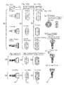
- IC tag 9 which is employed in this embodiment, will now be described with particular reference to Figs. 16 and 17. It is to be noted that the IC tag 4, described later, is similar to this IC tag 9. Recording and reading of information in and from the IC tags 4 and 9 are carried out by the use of a tag rcader/writer 20.
- the tag reader/writer 20 includes an antenna 21 that is directed towards the IC tags 4 and 9.
- the tag reader/writer 20 is controlled by an information processor 23 such as a computer.
- an information processor 23 such as a computer.
- the IC tags 4 and 9 are of a type capable of information reading on a non-contact basis and are each made up of an IC chip (a chip of an integrated circuit) 25 and an antenna 26.
- the IC chip 25 and the antenna 26 are integrally encapsulated by a resin (not shown).
- the IC tag is available in various types, shapes and sizes and may be rectangular or plate-like as well as squared or spherical of a size smaller than, for example. 1 mm and has a varying storage capacity, but the IC tag may be property selected in dependence on the type of an object to which it is fitted and in dependence on the size of the object. Since the IC tag 4 used for the control of the element 2 as will he described later is attached to a container 61 or the like (Figs. 22 and 23), it may be of a relatively large size, but the IC tag 9, which is fitted t) the constant velocity universal joints 13 and 13A.
- an RFID based IC tag that utilizes the RFID (Radio Frequency Identification) technology, can be utilized.
- the RFID based IC tag is available in various types utilizing electrostatic coupling, electromagnetic coupling, electromagnetic induction, microwaves and light for a transmission system and, of them, any type can be employed, but by way of example the IC tag or an electromagnetic induction type can be employed.
- the IC tag of a kind that can be utilized even in the presence of a metal nearby is available.
- the IC tag is attached to the constant velocity universal joints 13 and 13A and, in particular, where the IC tag is attached to a location other than the boots 18, such IC tag operable in the presence of a metal is preferred.
- Fig. 17 illustrates a specific example of a circuit of each of the IC tags 4 and 9.
- the IC chip 25 employed in each of the IC tags 4 and 9 includes a central processing unit (CPU) 27, a memory 28, a transmitting and receiving circui 29 and an electric power supply circuit 30.
- the electric power supply circuit 30 is of a type capable of acquiring an electric power from an antenna 26.
- the memory 28 is one that does not require an electric power source for the storage of information.
- the IC tags 9 attached to the constant velocity universal joints 13 and 13A ire used for the control of the identification information and the manufacturing information as described hereinbefore, but may be recorded with the status-of-use information associated with the use of the constant velocity universal joints 13 and 13A.
- the status-of-use information that is recorded in the IC tag 9 includes the total number of revolutions, the maximum number of revolutions, the temperature, the torque and so on and at least one of them is preferably recorded in the IC tag 9.
- the total number of revolutions may be, in the case of an automotive vehicle, information on the travel distance.
- the constant velocity universal joints 13 and 13A may be of a type forming respective parts of the vehicle drive shaft 11.
- the reade/writer 20 capable of communicating with the IC tag 9 and a write-in processor 41 for writing predetermined information in the IC tag 9 through this reader/writer 20 are mounted on the automotive vehicle, the status-of-use referred to above may be recorded in the IC tag 9 through the write-in processor 41.
- the write-in processor 41 may be provided in for example, an electric control unit (ECU) 42 for controlling the entirety of the automotive vehicle.
- ECU electric control unit
- the IC tag 9 generally requires no electric power source for the storage of information, writing and reading of the information in the IC tag 9 require the use of the reader/writer 20. With the reader/writer 20 and the write-in processor 41 mounted on the automotive vehicle, writing of information on the status-of-use of the constant velocity universal joints 13 and 13A can be automatically accomplished without requiring a vehicle driver to manipulate.
- the write-in processor 41 may have a function of regularly recording the stams-of-usc.
- the regular recording may be carried out at predetermined intervals of time such as, for example, once a day or at the time when a condition is satisfied other than time such as, for example, each time a key of the automotive vehicle is turned on.
- the write-in processor 41 performs a writing operation at a timing determined by a timer 43. Also, if the writing operation of the write-in processor 41 is initiated in response to the turn-on of an engine key 44, the writing can be carried out each time the key is turned on.
- the write-in processor 41 may be so designed as to record one or both of the travel distance and the maximum speed as the information on the status-of-use. Recording of the travel distance and the maximum speed may be accomplished by way of updating the contents recorded in the IC tag 9. Information on the travel distance and the maximum speed corresponds to information on the total number of revolutions and the maximum number of revolutions of each of the constant velocity universal joints 13 and 13A.
- the travel distance and the maximum speed can be discerned from respective detection values of a vehicle velocity sensor 45 and an odometer 46, which are inputted to the electric control unit (ECU) 42. If the travel distance and the maximum speed are recorded in the IC tags 9 attached to the constant velocity universal joints 13 and 13A, the records on the constant velocity universal joints 13 and 13A can be obtained. Although the storage capacity of the IC tag 9 decreases when the IC tag 9 is compactized, recording of the travel distance and the maximum speed in the form as updated is effective to avoid a shortage of the storage capacity.
- a sensor for detecting an object to be detected of the constant velocity universal joints 13 and 13A may be connected with the IC tag 9.
- the sensor 40 may be integrated on a chip or a substrate or the like together with the IC tag 9.
- a temperature sensor or a strain gauge for example, can be used.
- the sensor 40 If the sensor 40 is connected so that the detected information can be recorded in the IC tag 9, it is possible to record the status-of-use information such as the temperature of the constant velocity universal joints 13 and 13A and a loaded torque acting on them.
- constant velocity universal joints 13 and 13A emit heat in an amount that depends on the condition of use, knowing the temperature of the constant velocity universal joints 13, 13A is convenient in control of the status-of-use of the constant velocity universal joints 13, 13A. Also, if the constant velocity universal joints 13. 13A are used under an unreasonably loaded condition, an abnormal torque tends to be generated and, accordingly, if the torque is also recorded, it is convenient For servicing or diagnosis.
- Another item which can be preferably stored in the IC tag 9 with the use of the sensors 40 provided in the constant velocity universal joints 13 and 13A, includes an axial tension and a bending moment acting on the intermediate shaft 12 of the vehicle drive shaft 11.
- the bending moment affects excitation of the intermediate shaft 12 and can be used for clarification of the status of generation of a whining sound perceived within a vehicle compartment during the run of the automotive vehicle.
- the senso is employed in the form of a strain gauge.
- Fig. 21 illustrates a series of stages of flow of the constant velocity universal joint 13 from the manufacture thereof to the disposal thereof and quality control steps, in which the IC tag 9 is utilized at each of those flow stages.
- the sliding type constant velocity universal joint 13A is also controlled in a manner similar to the fixed type constant velocity universal joint 13.
- the quality control method for this shaft joint is a method in which the IC tag 9 is attached to the constant velocity universal joint 13, a predetermined manufacturing information ranging from purchase of material to examination through a forging step, a heat treatment step and a grinding step, all associated with the constant velocity universal joint 13, is recorded in the IC tag 9, and from the recorded information read out from the IC tag 9, traccability associated with the quality control of the constant velocity universal joint 13 is enabled.
- the forging step may include a substep of turning subsequent to the forging or, without the Forging step, turning may be carried out on the raw material.
- forging and turning step it is simply referred to as “forging step” in this specification.
- the IC tag 9 is of a type in or from which information can be recorded or read out, respectively, on a non-contact basis.
- the elements such as the outer race 14, the inner race 15, the balls 16.
- the retainers 17, the intermediate shaft 12 and the boots 18, all forming respective parts of the constant velocity universal joint 13, are collectively designated by a reference numeral "2".
- This quality control method for the shaft joint includes an IC tag attaching step R1, a manufacturing information recording step R2 and a recorded information reading and utilizing step R3.
- the IC tag 9 is attached to the constant velocity universal joint 13 at the time of manufacture of or at the time of completion of the manufacture of, the constant velocity universal joint 13.
- the constant velocity universal joint 13 may be assembled, or alternatively, the IC tag 9 may be attached to the constant velocity universal joint 13 after the assemblage of the constant velocity universal joint 13 completes.
- a predetermined manufacturing information ranging from the purchase of material to the examination hy way of the forging step, the heat treatment step and the grinding step, all associated with the constant velocity universal joint 13, is recorded in the IC tag 9, attached to this constant velocity universal joint 13, by the time the constant velocity universal joint is shipped or delivered to a customer.
- the manufacturing information recorded in this way includes a processing condition information on at least one of the forging, heat treatment and grinding steps.
- the purchase of material, the forging step, the heat treatment step and the grinding step, all associated with the constant velocity universal joint 13, are nothing other than the purchase of material, the forging step, the heat treatment step and the grinding step all associated with any of the eleme Its 2 forming the constant velocity universal joint 13.
- the processing condition information includes, for example, the press pressure, the cycle time and other parameters, so long as the forging step is concerned; the heat treatment temperature, the heating time and the heating method and other parameters, so long as the heat treatment step is concerned; and the rotational speed of a grinding stone, the cutting speed, the feed speed and other parameters, so long as the grinding step is concerned.
- the manufacturing information preferably includes at least one of pieces of information concerning the date of manufacture of the constant velocity universal joint 13, the place of manufacture of the constant velocity universal joint 13, the brand or the grease employed therein, the gap size between the elements employed, the term of warranty and handling cautions. Also, information on various results of examination is also preferably included in the manufacturing information.
- Those results of examination may include results of examination on each of the elements 2 and results of examination of the complete constant velocity universal joint 13.
- the manufacturing information may additionally include a piece of information on identification of the constant velocity universal joint 13.
- the identification information on the constant velocity universal joint 13 may include information on identification unique to each of the constant velocity universal joint 13, for example, the manufacturer's serial number and/or information on identification specific to a particular lot of the constant velocity universal joints 13, for example, the lot number. Recording of those pieces of manufacturing information may be carried out all at a time or on a piecemeal basis.
- This step is such that at an arbitrarily chosen time subsequent to the shipment, the information recorded in the IC, tag 9 is read out and at least the processing condition information is then confirmed from the information so read out.
- the flow of the constant velocity universal joint 13 from completion of the manufacture to disposal generally includes, as shown in Fig. 21.
- a specially ordered article it is delivered directly to a customer immediately after the shipment.
- Reading and utilization of the information recorded on the IC tag 9 takes place at any arbitrarily chosen time subsequent to the shipment, depending on the necessity and some of the pieces of the information so read out from the IC tag 9 are then confirmed.
- the reading of the information from the IC tag 9 can be accomplished by, for example, bringing the tag reader/writer 20 close to the automotive vehicle, as shown in Fig. 18, while the constant velocity universal joint 13 mounted on the automotive vehicle remains as mounted thereon. Because of this, the information on the constant velocity universal joint 13 can be simply and quickly made available.
- the information read out from the IC tag 9 may be outputted to the information processor 20b provided in the tag reader/writer 20.
- the tag reader/writer 20 is of a portable type and is of a type including a tag reader/writer unit 20a and the information processor 20b.
- the tag reader/writer 20 may be a tag reader having only a reading capability.
- a free storage space of the memory in the IC tag 9 attached to the constant velocity universal joint 13 is utilized suitably for storing information on, for example, shipment control, inventory control, distribution control and/or maintenance control. Also, it is used for storing information on control of the status-of-use of the constant Velocity universal joint 12 such as, for example, the maximum number of revolutions, It is to be noted that the IC tag 9 for the control of the status-of-use may be provided separate from the IC tag 9 for the control of the manufacturing information.
- one of the pieces of the processing condition information including the forging step, the heal treatment step, the grinding step and others can be confirmed during the information reading and utilizing step R3 taking place at any desired time subsequent to the shipment. Because of this, even in the constant velocity universal joint 13, which is required to have a severe quality and precision, it is possible to solve, for example, a technical problem occurring in the constant velocity universal joint 13. Also, in the case of this method, since the information can be controlled only by the IC tag 9 with no need to use any separate database, the processing condition information can be read out in the facilities, where the processing condition information is desired to be confirmed, from the IC tag 9 regardless of the use of communication facilities necessary to make access to the database and the access authority.
- the above described embodiment is a method of conducting the quality control by the use of the recorded information while the pieces of the manufacturing information has been recorded in the IC tag 9 as many as possible
- the IC tag 9 may be used in combination with a database 50.
- the database 50 is designed to store the predetermined manufacturing information on the flow from the purchase of material to the examination by way of the forging step, the heat treatment step and the grinding step with respect to the constant velocity universal joint 13 in association with the identification information on the constant velocity universal joint 13, so that contents stored in the database 50 can be extracted based on the identification information.
- the quality control is carried out by the utilization of the database 50 and the IC tag 9 attached to the constant velocity universal joint 13. In such case, during the various steps R1 to R3, the following processing takes place.
- This step R1 is identical with that described in connection with the previous embodiment.
- the identification information on the manufacture's serial number, the lot number or the like with respect to the constant velocity universal joint 13 and the manufacturing information on the constant velocity universal joint 13 are recorded on the IC tag 9 attached to the constant velocity universal joint 13, based on the database 50 at the time of shipment or by the time of delivery to a customer.
- the manufacturing information so recorded includes information on processing conditions of at least one of the forging, heat treatment and grinding steps with respect to each of the elements 2. Since the database 50 is used concurrently with the IC tag 9, the manufacturing information to be recorded on the IC tag 9 may be limited to only information that is convenient to read out directly from the IC tag 9. For example, pieces of information concerning the date of manufacture of the constant velocity universal joint 13, the place of manufacture of the constant velocity universal joint 13. the brand of the grease employed therein, the gap size between the elements 2 employed, the term of warranty and handling cautions are preferably recorded on the IC tag 9.
- the information recorded on the IC tag 9 is read out and one of confirmation of the purchased material, confirmation of the manufacturing process, confirmation of the processing condition information thereof, confirmation of the result of examination and others is carried out making reference to the information so read out or to information obtained by collating the information so read out with the database 50.
- Other information recorded on the IC tag 9 and the database 50 may be carried out.
- collection of the various pieces of the manufacturing information to be recorded during the manufacturing information recording step R2 may be carried out by recording them in a time-of-manufacture control database 54 and subsequently recording them on the IC tag 9 attached to the constant velocity universal joint 13 or, alternatively, on a different IC tag 4 for use during the manufacture, which is different from the IC tag 9 attached to the constant velocity universal joint 13.
- a method of recording in the time-of-manufacture control database 54 includes a step of recording in the time-of-manufacture control database 54, the manufacturing information on the manufacturing process including the purchase or material, the forging step, the heat treatment step, the grinding step and the examination step with respect to the elements 2 of the constant velocity universal joint 13, in association with the lot number of the elements 2 or the identification number for each of the elements 2, and a step of recording the information so recorded in the IC tag attached to the constant velocity universal joint 13.
- the time-of-manufaclure control database 54 is provided in one or a plurality of computers (not shown) linked to, for example, a computer network.
- This method includes a step of recording the manufacturing information on a manufacturing process with respect to the elements 2 of the constant velocity universal joint 13, including the purchase of material, the forging step, the heat treatment step, the grinding step and the examination step, on the IC tag 4 provided for each of the lot numbers of the elements 2, at each stage of the manufacturing process, and a step of reading the recorded information and then recording portion or the whole of the information so read out on the IC tag 9 attached to the constant velocity universal joint 13.
- the manufacturing information to be recorded on the IC tag 4 for use during the manufacture includes the processing condition information on at least one of the forging step, the heat treatment step and the grinding step.
- a method of utilizing the IC tag 4 for use during the manufacture may vary depending on whether the constant velocity universal joint 13 is individually examined such as is the case with the custom-made product or whether the constant velocity universal joint 13 is examined on a lot basis such as is the case with general products. In general, examination on a lot basis is employed.
- Fig. 22 illustrates the case with the individually examined products (specially ordered products) whereas Fig. 23 illustrates the case with the products examined on the lot basis (general products).
- the individually examined products (specially ordered products) and the product (general products) examined on the lot basis are substantially identical with each other, except that they are different from each other in respect of whether the examination after the grinding step and also after the assemblage is carried out individually or on the lot basis, the individually examined products (specially ordered products) will first be described and, as to the products examined on the lot basis, only the difference from the individually examined products (specially ordered products) will be described subsequently.
- the constant velocity universal joint 13 subject to the control by this quality control method is made by assembling different kinds of elements 2 ((1) to (n)) and each of those kinds of the elements 2 is manufactured sequentially through the material purchase step S1, the forging step S2, the heat treatment step S3 and the grinding step S4.
- the elements 2 manufactured through those steps S1 to S4 include the outer race 14, the inner race 15, the retainer 17 and the intermediate shaft 12.
- the constant velocity universal joint 13 may include elements 2 different from the elements 2 that are manufactured through the process including the material purchase step S1 to the grinding step S4 by way of the forging step S2 and the heat treatment step S3.
- Those different elements 2 include, for example, the boots 18.
- the flow from the material purchase step S1 to the grinding step S4 by way of the forging step S2 and the heat treatment step S3 represent broadly divided sections of the flow from purchase of material to completion of the elements 2. Each of those steps may include a plurality of substeps, or may include a step not included within the specific nomenclature.
- the nomenclatures used to denote the steps S1 to S4 are representative of the divided process steps.
- This control method employs the following stages (1) to (4) for each of the elements 2 ((1) to (n)), but employs such stages as will be described later for the constant velocity universal joint 13 made up of the elements 2. It is to be noted that although the number of lots may increase from one manufacturing step to the next manufacturing step on the downstream side of the manufacture, the elements 2 in one lot arc not combined with the elements 2 in different lots.
- the lot number of the material for each of the elements 2 and information concerning the purchased material for each of the elements 2 are recorded on each of the IC tags 4 prepared for each of the material lots 5.
- the IC tags 4 for each of the material lots 5, or new IC tags 4 succeeding the information recorded on the IC tags 4 for each of the material lots 5 are separately prepared for each of forging lots 6, and the forging lot number for the corresponding forging lot 6 and information that can be obtained during the forging step are subsequently recorded on those IC tags 4.
- the IC tags 4 for each of the forging lots 6, or new IC tags 4 succeeding the information recorded on the IC tags 4 for each of the forging lots 6 are separately prepared for each of heat treatment lots 7, and the heat treatment lot number for the corresponding heat treatment lot 7 and information that can be obtained during the heat treatment Step arc subsequently recorded in those IC tags 4.
- the IC tags 4 for each of the heat treatment lots 7, or new IC tags 4 succeeding the information recorded on the IC tags 4 for each of heat treatment lots 7 are separately prepared for each of grinding lots 8, and the processing conditions for the grinding lot 8 are recorded on the corresponding IC tag 4.
- the IC tags 4 for each of the grinding lots 8, or new IC tags 4 succeeding the information recorded on the IC tags 4 for each of the grinding lots 8 are separately prepared for each of the elements 2 or a set of the elements 2 of the same kind, which provides a unit of examination, and the corresponding grinding lot number and information obtained during the examining step are recorded on those IC tags 4.
- the IC tag 9. which may be used for the control of the constant velocity universal joint 13 after the completion, is attached to the constant velocity universal joint 13 made up of the elements 2 ((1) to (n)) during a period prior to the assemblage and after the assemblage.
- the manufacturing number unique to the individual constant velocity universal joint 13 and the information recorded on the IC tag 4 after the step of examination of each of the elements 2 ((1) to (n)) used to form the constant velocity universal joint 13 at least the manufacturing number is recorded on the IC tag 9 so attached to the constant velocity universal joint 13.
- the information recorded on the corresponding IC tag 4 about the manufacturing process of each of the elements 2 ((1) to (n)) used to form the constant velocity universal joint 13 and the information on examination after the completion of the constant velocity universal joint 13 are recorded in the database 50 in correspondence with the manufacturing number of the constant velocity universal joint 13.
- the IC tag 4 employed during each of the steps (S1) to (S4) may be identical throughout those steps S1 to S4, or a different IC tag 4 may be employed during each of those steps and the information recorded on the IC tag used during the preceding step may be transcribed on the different IC tag used during the following step.
- a new IC tag 4 may be prepared, on which the information recorded during the preceding step may be transcribed or, alternatively, while the IC tags 4 may be prepared in advance in a number equal to the number of lots that arc used throughout the manufacturing process, information can be additionally recorded on the same IC tag 4 throughout the manufacturing process.
- the IC tag 4 is attached to, for example, a transport container 61 accommodating therein the elements 2.
- the container 61 may be, for example, a cage, box or pallet.
- the IC tag 4 may be attached directly to the container 61 or may be attached to a visual identifying tag 62 attached to the container 61 as shown in Fig 27. Attachment of the IC tag 4 to the container 61 may be made removable.
- the IC tag 4 When the IC tag 4 is so attached to the container 61, the IC tag 4 prepared for each lot can be moved at all times together with the elements 2 and, therefore, the IC tag 4 can be handled easily.
- recording of the information on the IC tag 4 may be carried out along a path of transport path 63 of the clements 2 by means of, for example, a conveyor.
- the material is generally purchased in the form of steel ingots, steel plates, steel tubes, steel wires or the like.
- the materials so purchased are quality examined, for example, on a lot basis.
- Information (4a) on the purchased material that is recorded on the IC tag 4 at this control stage can be classified into information on the origin and information on the quality.
- the origin information is descriptive of the name of a selling company, the place of a factory of such selling company and so on.
- the quality information is descriptive of the hardness of texture, inclusions of non-metallie material and so on. This quality information is such that although the results of examination of the materials conducted after the purchase of the materials are recorded on the IC tag, the information obtained from the selling company can be recorded, or the both may be recorded.
- a method of recording the information on the IC tag 4 in this control stage may be carried out by recording the information available from, for example, a purchase control computer (not shown) by means of a recording terminal.
- the forging step (S2) varies depending on the kind of the constant velocity universal joint 13 and/or the kind of each of the elements 2. As described in connection with, for example, Fig. 10, the forging step (S2) includes a cold forging substep of forming the element 2 in a rough shape, a grinding substep of grinding the roughly forged product and other substeps.
- recording of the information (4b) on the IC tag 4 during the forging step (S2) may he carried out either all at a time for the forging step (S2) or during each of the substeps of the forging step (S2).
- the element 2 is one of the outer race 14, the inner race 15, the retainer 17 and the intermediate shaft 12 and the forging and turning or the turning with no forging is carried out as shown in Fig. 10 or Fig. 12, information on the dimensions of various parts of the elements 2 measured subsequent to the turning is recorded on the IC tag 4.
- the element 2 is the balls
- information on the dimensions, strains, appearance and others is recorded, for example, subsequent to the stamping and, also, information on the dimensions, sphericity- appearance and others measured after the brushing and also after the green machining is recorded. Processing condition information is also recorded.
- the method of recording the information (4b) on the IC tag 4 during this control stage is carried out through a terminal 55 by the time-of-manufacture control database 54.
- the time-of-manufacture control database 54 for example, for the process control or the examination control that is used for each step including, for example, the forging step (S2).
- the information required to he manually inputted by an operator it is recorded directly from the terminal 55 or through the time-of-manufacmrc control database 54 by way of an input device 55 such as a keyboard.
- new IC tags 4 are prepared, on which the information (4a) recorded on the IC tags 4 for the material lots 5 is then transcribed with the use or an IC tag duplicator 57, and the information (4b) on the forging step is then recorded on the new IC tags 4 having the information transcribed thereon. Even in each of the subsequent steps, the information is transcribed onto the new IC tags 4 where the number of lots increases in each of the subsequent steps.
- the grinding step (S4) may vary depending on the kind of the constant velocity universal joint 13 and the kind of the elements 2 used therein. Where the element 2 is the ball 16, rough grinding, medium grinding, tine grinding, lapping and so on are carried out. In those substeps, articles or manufacture completed are examined after each of those substeps.
- Information (4d) to be recorded on the IC tag 4 includes processing conditions for each of the substeps during the grinding step (S4). The information (4d) on those processing conditions may include, for example, the kind of a grinding stone, the grinding speed and others After completion of the grinding step, examination is conducted, results of which are recorded on the IC tag 4. Information (4d) on the results of the examination may include, for example, various dimensions and appearance.
- the information includes the dimensions, sphericity and others contained in results of examination after the rough grinding or any other substeps during the grinding step (S4).
- the information may further include the appearance, dimensions, sphericity, difference in diameter, hardness, acoustic test results, microscopic test results and others with respect to the elements 2 completed after the grinding step (S4).
- the entire number of the elements 2 are examined when they are the custom-made or specially ordered products.
- the IC tag 4 is prepared in a number equal to the number of the elements 2 and is recorded with such information as the grinding lot number, the individual results of examination and others for the corresponding element 2.
- the number necessary to identify the individual elements 2 may be additionally recorded in the corresponding IC tag 4.
- a set of the clements 2 used in each constant velocity universal joint 13 may be considered as a single element 2 and only one IC tag 4 may be prepared for each set of the element 2. with the information recorded thereon for each set.
- the elements 2 so manufactured as hereinbefore described are assembled into the constant velocity universal joint 13 during the assembling step.
- the IC tag 9 is attached to the constant velocity universal joint 13.
- the IC tag 9 may be attached either to the clements 2 prior to the assemblage of the constant velocity universal joint 13 or subsequent to the assemblage of the constant velocity universal joint 13.
- the constant velocity universal joint 13 is examined as a complete product. This examination is carried out after, for example, the IC tag 9 has been attached thereto, but may be carried out before the IC tag 9 is attached, depending on how it is attached, Examination of the completed product is carried out on the total number of the constant velocity universal joints 13 where they are a specially ordered product.
- the information recorded on the IC tag 4 in connection with each of the elements 2 forming respective parts of the constant velocity universal joint 13 is recorded through the database 50 in correspondence with the manufacturing number of the constant velocity universal joint 13 as shown in Fig. 26. Also, even the results of examination on the completed product arc recorded in correspondence with the manufacturing number of the constant velocity universal joint.
- the manufacturing number is a number unique to the individual constant velocity universal joint 13 and is represented by, for example, the serial number. Where the constant velocity universal joint 13 contains a different element (for example, boots 18) 2 which does not pass through the above manufacturing steps, information on this different element 2 is equally recorded in the database 50.
- the IC tag 9 attached to the constant velocity universal joint 13 in the manner described above contains at least the manufacturing number.
- the IC tag 9 may also contain the information recorded on the IC tag 4 in connection with each of the elements 2 and the result of examination of the complete product.
- the results of examination of the completed product are recorded on the IC tag 9 during the examination step and such information may be transcribed from the IC tag 9 onto the database 50.
- the IC tag 9 may be attached to not only the constant velocity universal joint 13. but also to a packaging container 70 (Fig. 21) for the constant velocity universal joint 13 and the manufacturing number and others may be recorded on the IC tag 9 attached to the packaging container 70.
- the database 50 is provided in a control computer system 59 placed in the environment of a computer network 58 as shown in Fig. 26.
- the above described information F associated with each of the constant velocity universal joints 13 is recorded on a storage unit 50a of this database 50.
- the computer network 58 may be a wide area network such as Internet or a combination of the wide area network with a local area network established within the premises of a factory or plant.
- the database 50 includes the storage unit 50a and a database control unit 50b operable to interface with the storage unit 50a and also to control searches for the information.
- the database 50 may be any type provided that it can be conceptually recognized as a database for the quality control, or may be an aggregation of physically separate databases, or may be a type capable of commonly sharing the information with any database employed for any other purpose,
- the database 50 may be an aggregation of a plurality of computers distributed in the computer network 58 or may share the information with the time-of-manufacture control database 54 or a database for the control of technical in formation.
- the database 50 may be connected through the network 58 with various information processing instruments installed within the premises of the factory or plant and/or portable or mobile terminals or information processing instruments 60 installed in technical departments, warehouses, business offices, and/or customer's business offices.
- the information on the history from the material purchase for the elements 2 to results of examination of the completed constant velocity universal joint 13 is stored in the database 50 and the manufacturing number or the constant velocity universal joint 13 is recorded in the IC tag 9 attached to the constant velocity universal joint 13. comparison of the manufacturing number with the database 50 makes it possible to control the relation between the history information and the constant velocity universal joint on one-to-one basis.
- the user of the constant velocity universal joint 13 or those who conduct maintenance servicing for the constant velocity universal joint 13 can know the history information on the constant velocity universal joint 13.
- the information generated in each or the manufacturing steps of the elements 2 for the constant velocity universal joint 13 is recorded on the IC tag 4, provided on a lot basis for each of the manufacturing steps, together with the lot number and, therefore, the detailed history information can be controlled.
- the manufacturing number of the constant velocity universal joint 13 is recorded on the IC tag 9 attached to such constant velocity universal joint 13, the storage area remaining in this IC tag 9 can he used freely for various applications after the manufacture, for example, shipment control, marketing control, customer control, maintenance control and so on.
- the constant velocity universal joint 13 where it is used as a constant velocity universal joint for automotive vehicles, is, after having been completely assembled, examined and shipped, generally transported to a warehouse and then delivered to a customer or an automotive vehicle manufacturer through a delivery office as described with reference to Fig. 21. In the case of the specially ordered products, they may be delivered directly to the customer after the shipment thereof.
- the customer or the automotive vehicle manufacturer will install the constant velocity universal joint 13 into an automotive vehicle and then sell it and, on the other hand, the owner, who purchased the automotive vehicle, uses the constant velocity universal joint 13 consequent on the use of the automotive vehicle and will eventually dispose of it when the lifetime expires or is ready to expire.
- the history information be ascertained by reading the manufacturing number recorded on the IC tag 9 attached to such constant velocity universal joint 13, but also the storage arca left unoccupied in the IC tag 9 can be utilized for any purpose.
- This control of the products to be examined lot-by-lot includes the following control stages (1) to (3) and (4) so long as the elements 2 ((1) to (n)) are concerned, and so lone as the constant velocity universal joint 13 assembled with those elements 2 is concerned, the control includes control stages as will be described later.
- the control stages (1) to (3) from the purchase of material to the heat treatment step previously described in connection with the individually examined products arc equally applicable to the lot-by-lot examined products and, therefore, those control stages (1) to (3) will not be reiterated.
- the IC tags 4 for each heat treatment lot 7 or the IC tags 4 each succeeding the information recorded on the corresponding IC tag 4 for each heat treatment lot 7, arc prepared for each grinding lot 8.
- the grinding lot number associated with the grinding lot 8 and information obtained during the examination step arc recorded on those IC tags 4.
- the process taken during the grinding step (S4) is equally applied not only to the lot examined products, but also the individually examined products. While the information recorded during this control level (4') is descriptive of results of examination for each grinding lot 8, the same items to be examined are applied to the lot examined products and also to the individually examined products so long as the elements 2 are concerned, and, accordingly, those results of examination are recorded. Although the items to be examined may be different between the lot examined products and the individually examined products, recording of the results of examination on the IC tags 4 should be made regardless of the difference in item to be examined.
- the IC tags 9 are attached to the constant velocity universal joints 13 each assembled with the elements 2 during a period prior to the assemblage and subsequent to the assemblage.
- the manufacturing lot number and the information recorded on the IC lags 4 after the step of examination of each of the elements 2 ((1) to (n)) employed to form the respective constant velocity universal joint 13 at least the manufacturing lot number is recorded in each of those IC tags 9 attached to the respective constant velocity universal joint 13.
- the information recorded on each of the IC tags 4 about the manufacturing steps S1 to S4 with respect to the elements 2 ((1) to (n)) used to form the respective constant velocity universal joint 13 and the information on examination of the constant velocity universal joint 13 after the completion of the latter are recorded in the database 50 in correspondence with the manufacturing lot number.
- control of the lot examined products is substantially similar to the control of the individually examined products, unless otherwise specified.
- this control method controls the constant velocity universal joint 13 on the manufacturing lot basis, it will not provide a one-to-one control between the constant velocity universal joint 13 and the history information. However, effects and advantages similar to those obtained by the previously described first quality control method for the individually examined products of the constant velocity universal joint 13 can be obtained by this control method. Comparison to the control computer system 10 is made using the lot number obtained from the IC tags 9 attached to the respective constant velocity universal joint 13.
Landscapes
- Engineering & Computer Science (AREA)
- General Engineering & Computer Science (AREA)
- Business, Economics & Management (AREA)
- Economics (AREA)
- Mechanical Engineering (AREA)
- Quality & Reliability (AREA)
- Physics & Mathematics (AREA)
- General Physics & Mathematics (AREA)
- Accounting & Taxation (AREA)
- Human Resources & Organizations (AREA)
- Manufacturing & Machinery (AREA)
- Finance (AREA)
- Development Economics (AREA)
- Ocean & Marine Engineering (AREA)
- Entrepreneurship & Innovation (AREA)
- Automation & Control Theory (AREA)
- Marketing (AREA)
- Operations Research (AREA)
- Strategic Management (AREA)
- Tourism & Hospitality (AREA)
- General Business, Economics & Management (AREA)
- Theoretical Computer Science (AREA)
- General Factory Administration (AREA)
Applications Claiming Priority (4)
| Application Number | Priority Date | Filing Date | Title |
|---|---|---|---|
| JP2004223748A JP2006046357A (ja) | 2004-07-30 | 2004-07-30 | 等速自在継手 |
| JP2004223746A JP4610257B2 (ja) | 2004-07-30 | 2004-07-30 | 等速自在継手の品質管理方法 |
| JP2004223747A JP2006048102A (ja) | 2004-07-30 | 2004-07-30 | 等速自在継手の使用状況管理方法 |
| PCT/JP2005/013558 WO2006011439A1 (ja) | 2004-07-30 | 2005-07-25 | 等速自在継手とその品質管理方法 |
Publications (2)
| Publication Number | Publication Date |
|---|---|
| EP1785796A1 true EP1785796A1 (de) | 2007-05-16 |
| EP1785796A4 EP1785796A4 (de) | 2010-05-05 |
Family
ID=35786189
Family Applications (1)
| Application Number | Title | Priority Date | Filing Date |
|---|---|---|---|
| EP05766282A Withdrawn EP1785796A4 (de) | 2004-07-30 | 2005-07-25 | Konstantgeschwindigkeits-universalverbindung und qualitätskontrollverfahren dafür |
Country Status (3)
| Country | Link |
|---|---|
| US (1) | US7979327B2 (de) |
| EP (1) | EP1785796A4 (de) |
| WO (1) | WO2006011439A1 (de) |
Families Citing this family (10)
| Publication number | Priority date | Publication date | Assignee | Title |
|---|---|---|---|---|
| US20110106717A1 (en) * | 2009-11-03 | 2011-05-05 | Alstom Technology Ltd. | Quality control record and data processing system for creating and maintaining same |
| US20140020250A1 (en) * | 2012-07-17 | 2014-01-23 | Schaeffler Technologies AG & Co. KG | Friction torque barcode |
| CN103821831B (zh) * | 2014-02-20 | 2016-08-17 | 上海理工大学 | 变截面变壁厚旋锻轴轻量化设计方法 |
| JP6042849B2 (ja) * | 2014-07-28 | 2016-12-14 | ファナック株式会社 | 非接触式icタグを利用するアラーム表示システム |
| JP6437758B2 (ja) * | 2014-08-12 | 2018-12-12 | Ntn株式会社 | 等速自在継手の接合タイプ外側継手部材の検査装置 |
| JP6618728B2 (ja) * | 2015-07-09 | 2019-12-11 | Ntn株式会社 | 等速自在継手の外側継手部材の製造方法および溶接部の超音波探傷検査方法 |
| JP6685683B2 (ja) * | 2015-09-24 | 2020-04-22 | Ntn株式会社 | 等速自在継手の外側継手部材の製造方法および溶接部の超音波探傷検査方法 |
| US20170213118A1 (en) * | 2016-01-22 | 2017-07-27 | Aktiebolaget Skf | Sticker, condition monitoring system, method & computer program product |
| US10019886B2 (en) | 2016-01-22 | 2018-07-10 | Aktiebolaget Skf | Sticker, condition monitoring system, method and computer program product |
| CN112338778A (zh) * | 2020-11-06 | 2021-02-09 | 卞智崑 | 一种石材三阶抛光装置 |
Citations (2)
| Publication number | Priority date | Publication date | Assignee | Title |
|---|---|---|---|---|
| US20010016520A1 (en) * | 1999-12-15 | 2001-08-23 | Koji Sahashi | Drive wheel bearing assembly |
| US20020186134A1 (en) * | 2001-06-11 | 2002-12-12 | The Timken Company | Bearing with data storage device |
Family Cites Families (21)
| Publication number | Priority date | Publication date | Assignee | Title |
|---|---|---|---|---|
| JPS6360011A (ja) | 1986-08-28 | 1988-03-16 | Sumitomo Metal Ind Ltd | 圧延機監視方法 |
| JP2844791B2 (ja) | 1990-01-26 | 1999-01-06 | トヨタ自動車株式会社 | 等速ジョイント |
| US5995898A (en) | 1996-12-06 | 1999-11-30 | Micron Communication, Inc. | RFID system in communication with vehicle on-board computer |
| JPH1185925A (ja) | 1997-09-11 | 1999-03-30 | Nippon Telegr & Teleph Corp <Ntt> | ワイヤレスidタグとそのシステム |
| JPH11248035A (ja) * | 1998-03-06 | 1999-09-14 | Awaji Sangyo Kk | パイプ用継手 |
| JP4132187B2 (ja) * | 1998-03-11 | 2008-08-13 | 株式会社ガスター | 製造情報管理システムおよび製造情報管理方法 |
| JP2000048066A (ja) | 1998-07-27 | 2000-02-18 | Hitachi Ltd | ライフサイクル管理方法、システム、および製品 |
| AR022299A1 (es) * | 1999-01-29 | 2002-09-04 | Sensormatic Electronics Corp | Manejo de produccion y operaciones utilizando etiquetas rfid de lectura/escritura |
| JP2002094300A (ja) * | 2000-09-18 | 2002-03-29 | Pfu Ltd | ロット管理システムおよびその制御方法ならびに記録媒体 |
| JP2002169858A (ja) | 2000-11-30 | 2002-06-14 | Mitsubishi Materials Corp | Rfid用タグを用いた物品管理方法 |
| JP2002188653A (ja) * | 2000-12-20 | 2002-07-05 | Ntn Corp | 等速自在継手 |
| JP3941620B2 (ja) * | 2001-08-31 | 2007-07-04 | 株式会社デンソーウェーブ | Idタグ内蔵電子機器 |
| JP4064078B2 (ja) | 2001-09-04 | 2008-03-19 | Ntn株式会社 | 動力伝達装置 |
| JP2003186519A (ja) | 2001-12-14 | 2003-07-04 | Toyota Motor Corp | 製品情報管理システム及び方法 |
| JP2003233652A (ja) * | 2002-02-12 | 2003-08-22 | Sharp Corp | 品質管理システム、品質管理方法、品質管理プログラム及び品質管理プログラムを記録した記録媒体 |
| JP2003271216A (ja) | 2002-03-14 | 2003-09-26 | Toppan Printing Co Ltd | 非接触icタグを用いた工程管理方法 |
| US6898489B1 (en) * | 2002-06-11 | 2005-05-24 | Pyper Products Corporation | Vehicle control system with radio frequency identification tag |
| JP2004033257A (ja) | 2002-06-28 | 2004-02-05 | Kpe Inc | 記憶装置、遊技機、遊技機用ユニットおよび遊技機の制御方法 |
| KR101018723B1 (ko) * | 2003-02-14 | 2011-03-04 | 엔티엔 가부시키가이샤 | Ic 태그를 사용한 기계 부품 및 그 품질 관리 방법 및이상 검사 시스템 |
| US7042346B2 (en) * | 2003-08-12 | 2006-05-09 | Gaige Bradley Paulsen | Radio frequency identification parts verification system and method for using same |
| JP2005084962A (ja) * | 2003-09-09 | 2005-03-31 | Ntn Corp | Icタグ付き機械要素部品 |
-
2005
- 2005-07-25 US US11/658,954 patent/US7979327B2/en not_active Expired - Fee Related
- 2005-07-25 WO PCT/JP2005/013558 patent/WO2006011439A1/ja active Application Filing
- 2005-07-25 EP EP05766282A patent/EP1785796A4/de not_active Withdrawn
Patent Citations (2)
| Publication number | Priority date | Publication date | Assignee | Title |
|---|---|---|---|---|
| US20010016520A1 (en) * | 1999-12-15 | 2001-08-23 | Koji Sahashi | Drive wheel bearing assembly |
| US20020186134A1 (en) * | 2001-06-11 | 2002-12-12 | The Timken Company | Bearing with data storage device |
Non-Patent Citations (1)
| Title |
|---|
| See also references of WO2006011439A1 * |
Also Published As
| Publication number | Publication date |
|---|---|
| WO2006011439A1 (ja) | 2006-02-02 |
| US7979327B2 (en) | 2011-07-12 |
| EP1785796A4 (de) | 2010-05-05 |
| US20090216360A1 (en) | 2009-08-27 |
Similar Documents
| Publication | Publication Date | Title |
|---|---|---|
| US7979327B2 (en) | Constant velocity universal joint and quality control method for the same | |
| EP1615091B1 (de) | Maschinenkomponente mit ic-etikett und verfahren zur qualitätskontrolle und system zur abnormitätsuntersuchung | |
| CN101040230B (zh) | 航空航天用机械元件商品的品质管理方法 | |
| EP1402492B1 (de) | Lager mit datenspeichereinrichtung | |
| AU2007250203B2 (en) | RFID data management system | |
| US7200466B2 (en) | Parts assembly management system | |
| US7471198B2 (en) | Machine component with IC tag attached thereto | |
| WO2006011438A1 (ja) | 車輪用軸受装置とその品質管理方法 | |
| CA2590642A1 (en) | Item-based monitoring systems and methods | |
| CN100474195C (zh) | 等速万向节及其品质管理方法 | |
| JP2006046357A (ja) | 等速自在継手 | |
| JP2006048102A (ja) | 等速自在継手の使用状況管理方法 | |
| JP4458981B2 (ja) | 機械要素商品の品質管理方法 | |
| JP4458980B2 (ja) | 機械要素商品の生産管理方法 | |
| JP2008129911A (ja) | ブレーキ製品の管理方法、icタグを有するブレーキ製品及びブレーキ製品管理システム | |
| JP4344918B2 (ja) | 加工情報記憶装置および加工情報追跡システム | |
| JP2006285891A (ja) | 装置の管理システム、及びその管理方法 | |
| CA2506472A1 (en) | System for transmitting a data stream from automobile to salesperson who sold it | |
| Onodera et al. | Modern cold forging applications for the manufacture of complex automotive parts | |
| US11927935B2 (en) | Near proximity non-contact can production tooling and tool characteristics identification and tracking system | |
| JP2006285892A (ja) | 転がり軸受装置の製造方法、及び転がり軸受装置 | |
| Li et al. | Concurrent intelligent manufacturing based on rfid | |
| CN109477738A (zh) | 用于存储与辊或轮的操作有关的信息的装置和方法以及所获得的辊或所获得的轮 | |
| KR102005249B1 (ko) | 차량 상태정보를 이용한 맞춤형 광고 시스템 및 방법 | |
| JP2006011551A (ja) | 生産システム |
Legal Events
| Date | Code | Title | Description |
|---|---|---|---|
| PUAI | Public reference made under article 153(3) epc to a published international application that has entered the european phase |
Free format text: ORIGINAL CODE: 0009012 |
|
| 17P | Request for examination filed |
Effective date: 20070228 |
|
| AK | Designated contracting states |
Kind code of ref document: A1 Designated state(s): DE FR |
|
| DAX | Request for extension of the european patent (deleted) | ||
| RBV | Designated contracting states (corrected) |
Designated state(s): DE FR |
|
| A4 | Supplementary search report drawn up and despatched |
Effective date: 20100406 |
|
| 17Q | First examination report despatched |
Effective date: 20100518 |
|
| GRAP | Despatch of communication of intention to grant a patent |
Free format text: ORIGINAL CODE: EPIDOSNIGR1 |
|
| RIC1 | Information provided on ipc code assigned before grant |
Ipc: F16D 3/223 20110101ALI20181205BHEP Ipc: G05B 19/418 20060101AFI20181205BHEP Ipc: F16C 3/02 20060101ALI20181205BHEP Ipc: G06Q 10/08 20120101ALI20181205BHEP |
|
| INTG | Intention to grant announced |
Effective date: 20190104 |
|
| RIN1 | Information on inventor provided before grant (corrected) |
Inventor name: IKEDA, TAKESHI Inventor name: KONDOU, HIDEKI |
|
| RIC1 | Information provided on ipc code assigned before grant |
Ipc: F16D 3/223 20110101ALI20181205BHEP Ipc: G06Q 10/08 20120101ALI20181205BHEP Ipc: F16C 3/02 20060101ALI20181205BHEP Ipc: G05B 19/418 20060101AFI20181205BHEP |
|
| STAA | Information on the status of an ep patent application or granted ep patent |
Free format text: STATUS: THE APPLICATION IS DEEMED TO BE WITHDRAWN |
|
| 18D | Application deemed to be withdrawn |
Effective date: 20190515 |