EP1784559B1 - Electromagnetically driven valve - Google Patents
Electromagnetically driven valve Download PDFInfo
- Publication number
- EP1784559B1 EP1784559B1 EP05753433A EP05753433A EP1784559B1 EP 1784559 B1 EP1784559 B1 EP 1784559B1 EP 05753433 A EP05753433 A EP 05753433A EP 05753433 A EP05753433 A EP 05753433A EP 1784559 B1 EP1784559 B1 EP 1784559B1
- Authority
- EP
- European Patent Office
- Prior art keywords
- valve
- stem
- disc
- driven valve
- prescribed direction
- Prior art date
- Legal status (The legal status is an assumption and is not a legal conclusion. Google has not performed a legal analysis and makes no representation as to the accuracy of the status listed.)
- Expired - Lifetime
Links
Images


Classifications
-
- F—MECHANICAL ENGINEERING; LIGHTING; HEATING; WEAPONS; BLASTING
- F01—MACHINES OR ENGINES IN GENERAL; ENGINE PLANTS IN GENERAL; STEAM ENGINES
- F01L—CYCLICALLY OPERATING VALVES FOR MACHINES OR ENGINES
- F01L1/00—Valve-gear or valve arrangements, e.g. lift-valve gear
- F01L1/20—Adjusting or compensating clearance
- F01L1/22—Adjusting or compensating clearance automatically, e.g. mechanically
- F01L1/24—Adjusting or compensating clearance automatically, e.g. mechanically by fluid means, e.g. hydraulically
-
- F—MECHANICAL ENGINEERING; LIGHTING; HEATING; WEAPONS; BLASTING
- F01—MACHINES OR ENGINES IN GENERAL; ENGINE PLANTS IN GENERAL; STEAM ENGINES
- F01L—CYCLICALLY OPERATING VALVES FOR MACHINES OR ENGINES
- F01L9/00—Valve-gear or valve arrangements actuated non-mechanically
- F01L9/20—Valve-gear or valve arrangements actuated non-mechanically by electric means
- F01L9/21—Valve-gear or valve arrangements actuated non-mechanically by electric means actuated by solenoids
- F01L2009/2125—Shaft and armature construction
-
- F—MECHANICAL ENGINEERING; LIGHTING; HEATING; WEAPONS; BLASTING
- F01—MACHINES OR ENGINES IN GENERAL; ENGINE PLANTS IN GENERAL; STEAM ENGINES
- F01L—CYCLICALLY OPERATING VALVES FOR MACHINES OR ENGINES
- F01L2309/00—Self-contained lash adjusters
Definitions
- the present invention generally relates to an electromagnetically driven valve, and more particularly to an electromagnetically driven valve of a rotary drive type used in an internal combustion engine and driven by electromagnetic force and elastic force.
- Japanese Patent Laying-Open No. 11-30113 discloses an electromagnetically driven apparatus aiming at prevention of generation of sound caused by friction or impact at the time of opening/closing of an intake/exhaust valve as well as attaining improvement in its characteristic of being mounted on an engine.
- the electromagnetically driven apparatus disclosed in this publication includes an armature accommodated in a casing in a vertically movable manner, a valve-closing electromagnet and a valve-opening electromagnet fixed to positions above and below the armature respectively, and a valve-opening side spring moving an intake valve toward a valve-opening direction through the armature.
- the electromagnetically driven apparatus structured as above is called a parallel drive type, in which electromagnetic force generated by the valve-closing electromagnet and the valve-opening electromagnet and elastic force by the valve-opening side spring directly act on a main shaft integrally formed with the armature, thereby causing the main shaft to carry out reciprocating motion.
- Japanese Patent Laying-Open No. 11-107723 discloses an electromagnetically driven valve aiming to realize excellent silence and power-saving capability.
- the electromagnetically driven valve disclosed in this publication is also of a parallel drive type, similar to the electromagnetically driven apparatus disclosed in Japanese Patent Laying-Open No. 11-30113 mentioned above.
- the electromagnetically driven valve of a rotary drive type includes a driven valve having a stem and carrying out reciprocating motion between a valve-opening position and a valve-closing position, a disc having one end in abutment to an end of the stem and the other end supported by a disc support base in a hinged manner, and an electromagnet applying electromagnetic force to the disc.
- the electromagnetically driven valve further includes a torsion bar provided at the other end of the disc and moving the driven valve toward the valve-opening position and a helical spring arranged around an outer circumference of the stem and moving the driven valve toward the valve-closing position. Elastic force of the spring and electromagnetic force generated as a result of current supply to the electromagnet cause the disc to oscillate around the other end. The movement of the disc is transmitted to the stem through one end, whereby the driven valve carries out reciprocating motion.
- an object of the present invention is to provide an electromagnetically driven valve attaining smooth reciprocating motion of the driven valve.
- An electromagnetically driven valve according to the present invention includes the features of claim 1:
- the buffer member is guided by the guide member along the prescribed direction. Accordingly, while movement of the buffer member in the direction orthogonal to the prescribed direction is restricted, displacement of the valve shaft produced in the orthogonal direction can be accommodated. At the same time, the buffer member contracts and expands in the prescribed direction, so that registration error of the valve element caused by a difference from the valve shaft in thermal expansion or part assembly error can be accommodated. Therefore, according to the present invention, smooth reciprocating motion of the driven valve can be achieved while sufficient sealing of the intake/exhaust port by means of the valve element is ensured.
- the valve shaft has a first shaft portion located on a side where one end is coupled with respect to the buffer member and a second shaft portion located on a side of the valve element with respect to the buffer member.
- the first shaft portion includes a first end surface abutting on a surface of the buffer member. The first end surface makes sliding movement with respect to the surface of the buffer member, so that displacement of the valve shaft produced in the direction orthogonal to the prescribed direction is accommodated.
- displacement of the valve shaft produced in the direction orthogonal to the prescribed direction can be accommodated by using a simplified structure.
- the second shaft portion includes a second end surface connected to a surface of the buffer member, and the first shaft portion is formed such that the first end surface has an area larger than that of the second end surface.
- an electromagnetically driven valve attaining smooth reciprocating motion of the driven valve can be provided.
- the electromagnetically driven valve implements an engine valve (an intake valve or an exhaust valve) in an internal combustion engine such as a gasoline engine or a diesel engine.
- an engine valve an intake valve or an exhaust valve
- an exhaust valve an exhaust valve
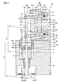
- an electromagnetically driven valve 10 is a rotary drive type electromagnetically driven valve. As an operation mechanism for the electromagnetically driven valve, a parallel link mechanism is applied.
- Electromagnetically driven valve 10 includes a driven valve 14 having a stem 12 extending in one direction and an umbrella-shaped portion 13 formed at a tip end of stem 12, and a lower disc 20 and an upper disc 30 coupled to different positions on stem 12 and oscillating by receiving electromagnetic force and elastic force applied thereto.
- Stem 12 is constituted of an upper stem 18 coupled to lower disc 20 and upper disc 30 and a lower stem 19 continuing from umbrella-shaped portion 13.
- Electromagnetically driven valve 10 further includes a lash adjuster 16 disposed between upper stem 18 and lower stem 19, and a guide ring 45 disposed on an outer circumference of lash adjuster 16 and guiding lash adjuster 16 along the direction in which stem 12 extends.
- Driven valve 14 carries out reciprocating motion in the direction in which stem 12 extends (a direction shown with an arrow 103), upon receiving the oscillating movement of lower disc 20 and upper disc 30.
- Driven valve 14 is mounted on a cylinder head 41 having an intake port 17 formed.
- a valve seat 42 is provided in a position where intake port 17 of cylinder head 41 communicates to a not-shown combustion chamber.
- the reciprocating motion of driven valve 14 causes umbrella-shaped portion 13 to intimately contact with valve seat 42 or to move away from valve seat 42, so as to open or close intake port 17.
- driven valve 14 is positioned at a valve-closing position.
- driven valve 14 is positioned at a valve-opening position.
- valve guide 43 for slidably guiding lower stem 19 in an axial direction is provided.
- Valve guide 43 is formed from a metal material such as stainless steel, in order to endure high-speed slide movement with respect to lower stem 19.
- a collar-shaped lower retainer 8 is fixed to an outer circumferential surface of lower stem 19, at a position apart from valve guide 43.
- a hollow portion 9 opening toward a top surface side is formed in cylinder head 41.
- Hollow portion 9 houses a lower spring 11 between a bottom surface of hollow portion 9 and lower retainer 8. Lower spring 11 applies the elastic force to driven valve 14 in such a direction that lower retainer 8 moves away from the bottom surface of hollow portion 9, that is, in a direction elevating lower stem 19.
- Lash adjuster 16 is constituted of an upper lid and a lower lid arranged with a prescribed gap therebetween and a viscous member filling the gap between the upper lid and the lower lid, such as grease or oil. With such a structure, lash adjuster 16 can freely expand and contract in the direction in which stem 12 extends. Lash adjuster 16 is shaped like a column, and includes a top surface 16a and a bottom surface 16b facing upper stem 18 and lower stem 19 respectively and a slide surface 16c extending between top surface 16a and bottom surface 16b.
- a tip end of lower stem 19 opposite to the tip end where umbrella-shaped portion 13 is formed is connected to bottom surface 16b of lash adjuster 16. That is, umbrella-shaped portion 13 and lash adjuster 16 are provided at opposing ends of lower stem 19, and lower retainer 8 is fixed at a position therebetween.
- Upper stem 18 has an end surface 18a facing top surface 16a.
- Upper stem 18 is provided, with respect to lash adjuster 16, in such a manner that end surface 18a abuts on top surface 16a.
- Slide surface 16c of lash adjuster 16 extends, with a distance from the outer circumferential surface of upper stem 18 and lower stem 19 in a radial direction. That is, lash adjuster 16 has a diameter larger than that of upper stem 18 and lower stem 19.
- Guide ring 45 has an annular shape, and has a guide surface 45c extending along an inner circumference. Guide surface 45c and slide surface 16c of lash adjuster 16 face and slidably contact with each other.
- a coupling pin 12p protruding from the outer circumferential surface and a coupling pin 12q protruding from the outer circumferential surface at a position apart from coupling pin 12p are formed.
- disc support base 51 supporting lower disc 20 and upper disc 30 so as to allow free oscillation thereof is provided.
- An electromagnet 60 for applying electromagnetic force to lower disc 20 and upper disc 30 is attached to disc support base 51.
- Electromagnet 60 is provided in disc support base 51 at a position between lower disc 20 and upper disc 30.
- Electromagnet 60 is constituted of a valve-opening/closing coil 62 and a valve-opening/closing core 61 formed from a magnetic material and having attraction and contact surfaces 61a and 61b.
- Valve-opening/closing core 61 has a shaft portion 61 p extending in a direction orthogonal to the direction in which stem 12 extends.
- Valve-opening/closing coil 62 is provided in a manner wound around shaft portion 61 p, and implemented by a monocoil (a coil implemented by a continuous wire). It is noted that valve-opening/closing coil 62 may be implemented by winding a plurality of coils, without limited to the monocoil.
- Disc support base 51 further includes a valve-opening permanent magnet 55 and a valve-closing permanent magnet 56 located on a side opposite to valve-opening permanent magnet 55 with electromagnet 60 being interposed
- Valve-opening permanent magnet 55 has an attraction and contact surface 55a, and a space in which lower disc 20 oscillates is defined between attraction and contact surface 55a and attraction and contact surface 61 b of electromagnet 60.
- valve-closing permanent magnet 56 has an attraction and contact surface 56a, and a space in which upper disc 30 oscillates is defined between attraction and contact surface 56a and attraction and contact surface 61a of electromagnet 60.
- lower disc 20 has one end 22 and the other end 23, and extends from the other end 23 to one end 22 in a direction intersecting stem 12.
- Lower disc 20 is constituted of an arm portion 21 having rectangular surfaces 21 a and 21 b formed and extending between one end 22 and the other end 23, and a shaft-receiving portion 28 having a hollow cylindrical shape and provided at the other end 23.
- Surfaces 21 a and 21 b face attraction and contact surface 61 b of electromagnet 60 and attraction and contact surface 55a of valve-opening permanent magnet 55, respectively.
- Arm portion 21 has a notch 29 formed on the side of one end 22, and annular holes 24 are formed in opposing wall surfaces of notch 29.
- Shaft receiving portion 28 has a through hole 27 formed, which extends along central axis 25.
- Upper disc 30 is shaped similarly to lower disc 20, and one end 32, the other end 33, an arm portion 31, a surface 31b, a surface 31a, a notch 39, a hole 34, a shaft receiving portion 38, a through hole 37, and a central axis 35 corresponding to one end 22, the other end 23, arm portion 21, surface 21a, surface 21b, notch 29, hole 24, shaft receiving portion 28, through hole 27, and central axis 25 of lower disc 20 respectively are formed.
- Surfaces 31a and 31b face attraction and contact surface 61a of electromagnet 60 and attraction and contact surface 56a of valve-closing permanent magnet 56, respectively.
- Lower disc 20 and upper disc 30 are formed from a magnetic material.
- One end 22 of lower disc 20 is rotatably coupled to upper stem 18 by fitting of coupling pin 12p into hole 24.
- One end 32 of upper disc 30 is rotatably coupled to upper stem 18 by fitting of coupling pin 12q into hole 34. Coupling pins 12p and 12q are permitted only to rotate in holes 24 and 34.
- lower disc 20 and upper disc 30 oscillate around central axes 25 and 35 respectively, whereby driven valve 14 carries out reciprocating motion along the direction in which stem 12 extends.
- Lower torsion bar 26 and upper torsion bar 36 apply elastic force to lower disc 20 and upper disc 30, in a manner moving the same counterclockwise around central axes 25 and 35, respectively. While the electromagnetic force from electromagnet 60 is not yet applied, lower disc 20 and upper disc 30 are positioned by lower torsion bar 26, upper torsion bar 36, and lower spring 11 at a position intermediate between an oscillation end on a valve-opening side and an oscillation end of a valve-closing side.
- valve-opening/closing coil 62 is supplied with a current flowing in a direction shown with an arrow 111 around shaft portion 61p of valve-opening/closing core 61.
- the current flows from the back toward the front of the sheet showing Fig. 4 .
- magnetic flux flows in valve-opening/closing core 61 in a direction shown with an arrow 112, and the electromagnetic force attracting upper disc 30 toward attraction and contact surface 61a of electromagnet 60 is generated.
- lower disc 20 is attracted to attraction and contact surface 55a by valve-opening permanent magnet 55. Consequently, upper disc 30 and lower disc 20 resist the elastic force of lower spring 11 in Fig. 1 , and they are held at the oscillation end on the valve-opening side shown in Fig. 4 .
- valve-opening/closing coil 62 at the position beyond the intermediate position, a current is again fed to valve-opening/closing coil 62 in a direction shown with arrow 111.
- the current flows from the front toward the back of the sheet showing Fig. 6 .
- magnetic flux flows in valve-opening/closing core 61 in a direction shown with an arrow 132, and the electromagnetic force attracting lower disc 20 toward attraction and contact surface 61 b of electromagnet 60 is generated.
- upper disc 30 is attracted to attraction and contact surface 56a by valve-closing permanent magnet 56.
- upper disc 30 is also attracted to attraction and contact surface 61 a of electromagnet 60 by the electromagnetic force generated by electromagnet 60.
- the electromagnetic force is stronger between lower disc 20 and electromagnet 60 because a space therebetween is narrow. Therefore, upper disc 30 and lower disc 20 oscillate from the position beyond the intermediate position to the oscillation end on the valve-closing side shown in Fig. 6
- lash adjuster 16 expands and contracts in the direction in which stem 12 extends, so as to accommodate registration error of driven valve 14 at the valve-closing position in Fig. 6 . Accordingly, intimate contact of umbrella-shaped portion 13 with valve seat 42 is ensured, thereby ensuring sealing between intake port 17 and the combustion chamber.
- the parallel link mechanism causing lower disc 20 and upper disc 30 to simultaneously oscillate in order to allow reciprocating motion of driven valve 14 is adopted. Actually, however, registration error of driven valve 14 tends to occur due to dimension error or assembly error caused among disc parts. Therefore, lash adjuster 16 is particularly effective in electromagnetically driven valve 10 including the parallel link mechanism.
- valve-opening/closing coil 62 is repeatedly started and stopped at a timing described above.
- upper disc 30 and lower disc 20 are caused to oscillate between the oscillation ends on the valve-opening side and the valve-closing side, so that driven valve 14 carries out the reciprocating motion as a result of the oscillating movement.
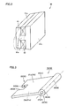
- Fig. 7 schematically shows movement of the lower disc and the upper disc oscillating from the oscillation end on the valve-closing side to the oscillation end on the valve-opening side as well as the lash adjuster lowered with such movement.
- end surface 18a of upper stem 18 makes a sliding movement in a horizontal direction with respect to top surface 16a of lash adjuster 16, so that displacement of upper stem 18 to the direction orthogonal to stem 12 is accommodated.
- Fig. 8 shows a slide portion 71 on top surface 16a, where sliding movement with respect to end surface 18a is made.
- lash adjuster 16 is guided by guide ring 45 along the direction in which stem 12 extends. Therefore, even if force in the direction orthogonal to stem 12 is applied due to sliding movement with respect to end surface 18a, lash adjuster 16 does not move in that direction.
- oscillating movement of lower disc 20 and upper disc 30 can be converted to reciprocating motion of driven valve 14, without transmitting displacement of upper stem 18 in the direction orthogonal to stem 12 to lower stem 19.
- top surface 16a may be subjected to surface treatment, such as polished finish of top surface 16a of lash adjuster 16 or appropriate metal coating of top surface 16a. In such a case, smooth sliding between end surface 18a and top surface 16a can be achieved, and abrasion resistance of slide portion 71 can be improved.
- surface treatment such as polished finish of top surface 16a of lash adjuster 16 or appropriate metal coating of top surface 16a.
- lash adjuster 16 and upper stem 18 are formed from different materials. Then, such a state that end surface 18a and top surface 16a slid with respect to each other and brought in contact with each other are more susceptible to chemical bond can be prevented. This is also the case between lash adjuster 16 and guide ring 45 as well as between coupling pins 12p, 12q and lower disc 20 and upper disc 30, that are slid with respect to each other and brought in contact with each other in a similar manner.
- Electromagnetically driven valve 10 includes driven valve 14 having stem 12 serving as a valve shaft extending in a prescribed direction and umbrella-shaped portion 13 serving as a valve element provided at the tip end of stem 12 and opening/closing the intake/exhaust port, lower disc 20 and upper disc 30 serving as oscillating members having one ends 22 and 32 coupled to stem 12 and the other ends 23 and 33 supported by disc support base 51 serving as a supporting member so as to allow free oscillation of the disc respectively and oscillating around the other ends 23 and 33 so as to cause driven valve 14 to carry out reciprocating motion in the prescribed direction, lash adjuster 16 serving as a buffer member provided in stem 12 between the tip end where umbrella-shaped portion 13 is provided and positions where one ends 22 and 32 are coupled respectively, and guide ring 45 serving as a guide member guiding lash adjuster 16 along the prescribed direction. Lash adjuster 16 contracts and expands in the prescribed direction and accommodates displacement of stem 12 produced in the direction orthogonal to the prescribed direction as a result of reciprocating motion of driven
- Stem 12 has upper stem 18 serving as a first shaft portion located on a side where one ends 22 and 32 are coupled with respect to lash adjuster 16, and lower stem 19 serving as a second shaft portion located on a side of umbrella-shaped portion 13 with respect to lash adjuster 16.
- Upper stem 18 includes end surface 18a serving as a first end surface abutting on top surface 16a serving as the surface of lash adjuster 16. End surface 18a makes sliding movement with respect to top surface 16a of lash adjuster 16, so as to accommodate displacement of stem 12 produced in the direction orthogonal to the prescribed direction.
- a plurality of lower discs 20 and upper discs 30 serving as the oscillating members are provided, with a distance from one another in the direction in which stem 12 serving as the valve shaft extends.
- Electromagnets 60 having valve-opening/closing coil 62 implemented by the monocoil are arranged among lower discs 20 and upper discs 30 serving as the plurality of oscillating members.
- lash adjuster 16 can convert the oscillating movement of lower disc 20 and upper disc 30 into linear movement of stem 12, to achieve smooth reciprocating motion of driven valve 14. At the same time, sufficient sealing between umbrella-shaped portion 13 and valve seat 42 can be ensured by means of lash adjuster 16.
- guide ring 45 is provided in electromagnetically driven valve 10 so as to guide lash adjuster 16. Therefore, as compared with an example in which guide ring 45 guides stem 12, radius of curvature of slide surface 16c and guide surface 45c at a contact position can be made larger. Accordingly, pressure on the contact surface between slide surface 16c and guide surface 45c can be lowered, whereby abrasion resistance of guide ring 45 can be improved.
- An electromagnetically driven valve according to the present embodiment is structured in a manner basically similar to the electromagnetically driven valve in the first embodiment. Therefore, description of a redundant structure will not be repeated.
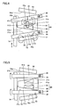
- Fig. 9 is an enlarged view of a region of the electromagnetically driven valve where the lash adjuster is provided.
- an end surface 19a is defined at a position of lower stem 19 connected to bottom surface 16b of lash adjuster 16.
- the tip end of upper stem 18 is formed like a collar, such that end surface 18a has an area larger than an area of end surface 19a.
- An electromagnetically driven valve according to the present embodiment is structured in a manner basically similar to the electromagnetically driven valve in the first embodiment. Therefore, description of a redundant structure will not be repeated.
- Fig. 10 is an enlarged view of a region of the electromagnetically driven valve where the lash adjuster is provided.
- lash adjuster 16 is constituted of an upper lid 81 having top surface 16a, a lower lid 83 arranged with a prescribed distance from upper lid 81 and having bottom surface 16b, and a viscous member 82 filling a gap between upper lid 81 and lower lid 83, such as grease and oil.
- lower retainer 8 in Fig. 1 is not provided in lower stem 19.
- Lower spring 11 is housed in hollow portion 9 between the bottom surface of hollow portion 9 and lower lid 83.
- lash adjuster 16 serving as the buffer member includes upper lid 81 abutting on upper stem 18 serving as the first shaft portion, lower lid 83 connected to lower stem 19 serving as the second shaft portion and arranged at a position distant from upper lid 81, and viscous member 82 filling the gap between upper lid 81 and lower lid 83.
- the electromagnetically driven valve further includes lower spring 11 serving as the spring member, which is provided on a side opposite to viscous member 82, with either upper lid 81 or lower lid 83 being interposed, and applies elastic force to stem 12 serving as the valve shaft.
- Lower spring 11 serving as the spring member moves either upper lid 81 or lower lid 83.
- lash adjuster 16 is formed integrally with lower retainer 8, whereby the number of parts of the electromagnetically driven valve can be reduced.
- the first to third embodiments have described an example adopting a parallel link mechanism in an electromagnetically driven valve of a rotary drive type, however, the present invention is not limited thereto.
- the present invention is applicable to an electromagnetically driven valve including one disc having one end coupled to stem 12 and the other end supported by disc support base 51 so as to allow free oscillation of the disc and a plurality of electromagnets arranged above and below the disc and alternately applying electromagnetic force to the disc, in a manner similar to the first to third embodiments.
- the present invention is mainly utilized as an intake valve or an exhaust valve in a gasoline engine, a diesel engine, or the like.
Landscapes
- Engineering & Computer Science (AREA)
- Mechanical Engineering (AREA)
- General Engineering & Computer Science (AREA)
- Valve Device For Special Equipments (AREA)
- Magnetically Actuated Valves (AREA)
- Mechanically-Actuated Valves (AREA)
Applications Claiming Priority (2)
| Application Number | Priority Date | Filing Date | Title |
|---|---|---|---|
| JP2004254193A JP2006070968A (ja) | 2004-09-01 | 2004-09-01 | 電磁駆動弁 |
| PCT/JP2005/011687 WO2006025146A1 (en) | 2004-09-01 | 2005-06-20 | Electromagnetically driven valve |
Publications (2)
| Publication Number | Publication Date |
|---|---|
| EP1784559A1 EP1784559A1 (en) | 2007-05-16 |
| EP1784559B1 true EP1784559B1 (en) | 2008-02-20 |
Family
ID=34970941
Family Applications (1)
| Application Number | Title | Priority Date | Filing Date |
|---|---|---|---|
| EP05753433A Expired - Lifetime EP1784559B1 (en) | 2004-09-01 | 2005-06-20 | Electromagnetically driven valve |
Country Status (6)
| Country | Link |
|---|---|
| US (1) | US20070252099A1 (enExample) |
| EP (1) | EP1784559B1 (enExample) |
| JP (1) | JP2006070968A (enExample) |
| CN (1) | CN101010494A (enExample) |
| DE (1) | DE602005004927T2 (enExample) |
| WO (1) | WO2006025146A1 (enExample) |
Families Citing this family (3)
| Publication number | Priority date | Publication date | Assignee | Title |
|---|---|---|---|---|
| FR2907500B1 (fr) * | 2006-10-24 | 2009-01-23 | Valeo Sys Controle Moteur Sas | Ensemble d'une soupape de cylindre et d'un actionneur de rappel de la soupape |
| JP5667528B2 (ja) * | 2011-06-28 | 2015-02-12 | 株式会社エー・アンド・デイ | 自動血圧測定装置の排気弁 |
| CN110541959B (zh) * | 2019-08-26 | 2021-02-19 | 珠海格力电器股份有限公司 | 电动蝶阀及空调装置 |
Family Cites Families (14)
| Publication number | Priority date | Publication date | Assignee | Title |
|---|---|---|---|---|
| DE4427943A1 (de) * | 1994-08-06 | 1996-02-08 | Schaeffler Waelzlager Kg | Hydraulisches Spielausgleichselement für die Ventilsteuerung von Brennkraftmaschinen |
| DE69517335T2 (de) * | 1994-11-09 | 2001-01-04 | Aura Systems Inc., El Segundo | Elektromagnetisch gelenktes ventil mit gelenkter armatur |
| DE19728479C2 (de) * | 1997-07-05 | 2001-08-30 | Daimler Chrysler Ag | Vorrichtung zur Betätigung eines Gaswechselventils mit einem elektromagnetischen Aktuator |
| DE19831520A1 (de) * | 1998-07-14 | 2000-01-20 | Schaeffler Waelzlager Ohg | Elektromagnetischer Ventiltrieb |
| DE19955054A1 (de) * | 1998-11-16 | 2000-08-17 | Heinz Leiber | Elektromagnetischer Antrieb |
| DE10013704A1 (de) * | 2000-03-21 | 2001-09-27 | Heinz Leiber | Antrieb eines Ventils eines Verbrennungsmotors mit einem elektromagnetischen Aktuator |
| JP2002147210A (ja) * | 2000-11-16 | 2002-05-22 | Honda Motor Co Ltd | 内燃機関の電磁駆動弁 |
| DE10136497A1 (de) * | 2001-07-27 | 2003-02-06 | Heinz Leiber | Verfahren zur Bestimmung des Spiels zwischen dem Schaft eines Ventils und einem Aktuator und Aktuator zur Durchführung des Verfahrens |
| JP2003065461A (ja) * | 2001-08-24 | 2003-03-05 | Toyota Motor Corp | 電磁駆動弁の制御装置 |
| US20030177989A1 (en) * | 2002-02-21 | 2003-09-25 | Baker Mark S. | Electromagnetic valve actuator for an internal combustion engine |
| DE10212007A1 (de) * | 2002-03-18 | 2003-10-02 | Heinz Leiber | Elektromagnetischer Antrieb |
| DE10231374A1 (de) * | 2002-07-11 | 2004-01-22 | Daimlerchrysler Ag | Aktuator |
| DE10233043A1 (de) * | 2002-07-20 | 2004-02-05 | Daimlerchrysler Ag | Einrichtung zum Betätigen eines Gaswechselventils |
| US7255073B2 (en) * | 2003-10-14 | 2007-08-14 | Visteon Global Technologies, Inc. | Electromechanical valve actuator beginning of stroke damper |
-
2004
- 2004-09-01 JP JP2004254193A patent/JP2006070968A/ja not_active Withdrawn
-
2005
- 2005-06-20 EP EP05753433A patent/EP1784559B1/en not_active Expired - Lifetime
- 2005-06-20 WO PCT/JP2005/011687 patent/WO2006025146A1/en not_active Ceased
- 2005-06-20 DE DE602005004927T patent/DE602005004927T2/de not_active Expired - Lifetime
- 2005-06-20 CN CNA2005800293425A patent/CN101010494A/zh active Pending
- 2005-06-20 US US11/632,660 patent/US20070252099A1/en not_active Abandoned
Also Published As
| Publication number | Publication date |
|---|---|
| DE602005004927T2 (de) | 2009-01-22 |
| US20070252099A1 (en) | 2007-11-01 |
| CN101010494A (zh) | 2007-08-01 |
| DE602005004927D1 (de) | 2008-04-03 |
| EP1784559A1 (en) | 2007-05-16 |
| JP2006070968A (ja) | 2006-03-16 |
| WO2006025146A1 (en) | 2006-03-09 |
Similar Documents
| Publication | Publication Date | Title |
|---|---|---|
| JP2010530621A (ja) | 電磁駆動装置 | |
| EP1714010B1 (en) | Electromagnetically driven valve | |
| EP1784559B1 (en) | Electromagnetically driven valve | |
| EP1789659B1 (en) | Electromagnetically driven valve | |
| US20070221873A1 (en) | Electromagnetically Driven Valve | |
| JP4124183B2 (ja) | 電磁駆動弁およびその制御方法 | |
| US20070290156A1 (en) | Electromagnetically Driven Valve | |
| JP3125605B2 (ja) | 内燃機関の電磁駆動式バルブ装置 | |
| US7387094B2 (en) | Electromagnetically driven valve | |
| JP2008303783A (ja) | 電磁駆動弁 | |
| US6732684B2 (en) | Solenoid-type valve actuator for internal combustion engine | |
| JP4140596B2 (ja) | 電磁駆動弁および内燃機関 | |
| JP2007170625A (ja) | 電磁駆動弁 | |
| EP1749982A2 (en) | Electromagnetically driven valve | |
| JP2007170466A (ja) | 電磁駆動弁 | |
| JP2001020708A (ja) | バルブ駆動装置 | |
| JP2010001812A (ja) | フラップ式電磁駆動弁 |
Legal Events
| Date | Code | Title | Description |
|---|---|---|---|
| PUAI | Public reference made under article 153(3) epc to a published international application that has entered the european phase |
Free format text: ORIGINAL CODE: 0009012 |
|
| 17P | Request for examination filed |
Effective date: 20070125 |
|
| AK | Designated contracting states |
Kind code of ref document: A1 Designated state(s): DE FR GB |
|
| GRAP | Despatch of communication of intention to grant a patent |
Free format text: ORIGINAL CODE: EPIDOSNIGR1 |
|
| DAX | Request for extension of the european patent (deleted) | ||
| RBV | Designated contracting states (corrected) |
Designated state(s): DE FR GB |
|
| GRAS | Grant fee paid |
Free format text: ORIGINAL CODE: EPIDOSNIGR3 |
|
| GRAA | (expected) grant |
Free format text: ORIGINAL CODE: 0009210 |
|
| AK | Designated contracting states |
Kind code of ref document: B1 Designated state(s): DE FR GB |
|
| REG | Reference to a national code |
Ref country code: GB Ref legal event code: FG4D |
|
| REF | Corresponds to: |
Ref document number: 602005004927 Country of ref document: DE Date of ref document: 20080403 Kind code of ref document: P |
|
| ET | Fr: translation filed | ||
| PLBE | No opposition filed within time limit |
Free format text: ORIGINAL CODE: 0009261 |
|
| STAA | Information on the status of an ep patent application or granted ep patent |
Free format text: STATUS: NO OPPOSITION FILED WITHIN TIME LIMIT |
|
| 26N | No opposition filed |
Effective date: 20081121 |
|
| REG | Reference to a national code |
Ref country code: GB Ref legal event code: 746 Effective date: 20130326 |
|
| REG | Reference to a national code |
Ref country code: DE Ref legal event code: R084 Ref document number: 602005004927 Country of ref document: DE Effective date: 20130319 |
|
| PGFP | Annual fee paid to national office [announced via postgrant information from national office to epo] |
Ref country code: GB Payment date: 20140618 Year of fee payment: 10 |
|
| PGFP | Annual fee paid to national office [announced via postgrant information from national office to epo] |
Ref country code: DE Payment date: 20140618 Year of fee payment: 10 |
|
| PGFP | Annual fee paid to national office [announced via postgrant information from national office to epo] |
Ref country code: FR Payment date: 20140609 Year of fee payment: 10 |
|
| REG | Reference to a national code |
Ref country code: DE Ref legal event code: R119 Ref document number: 602005004927 Country of ref document: DE |
|
| GBPC | Gb: european patent ceased through non-payment of renewal fee |
Effective date: 20150620 |
|
| REG | Reference to a national code |
Ref country code: FR Ref legal event code: ST Effective date: 20160229 |
|
| PG25 | Lapsed in a contracting state [announced via postgrant information from national office to epo] |
Ref country code: GB Free format text: LAPSE BECAUSE OF NON-PAYMENT OF DUE FEES Effective date: 20150620 Ref country code: DE Free format text: LAPSE BECAUSE OF NON-PAYMENT OF DUE FEES Effective date: 20160101 |
|
| PG25 | Lapsed in a contracting state [announced via postgrant information from national office to epo] |
Ref country code: FR Free format text: LAPSE BECAUSE OF NON-PAYMENT OF DUE FEES Effective date: 20150630 |