EP1779397B1 - Commutateur, procede d'actionnement dudit commutateur et utilisation dudit commutateur - Google Patents
Commutateur, procede d'actionnement dudit commutateur et utilisation dudit commutateur Download PDFInfo
- Publication number
- EP1779397B1 EP1779397B1 EP05755013.9A EP05755013A EP1779397B1 EP 1779397 B1 EP1779397 B1 EP 1779397B1 EP 05755013 A EP05755013 A EP 05755013A EP 1779397 B1 EP1779397 B1 EP 1779397B1
- Authority
- EP
- European Patent Office
- Prior art keywords
- contact
- resistance
- operating
- diverter switch
- main
- Prior art date
- Legal status (The legal status is an assumption and is not a legal conclusion. Google has not performed a legal analysis and makes no representation as to the accuracy of the status listed.)
- Not-in-force
Links
- 238000000034 method Methods 0.000 title claims description 22
- 230000033001 locomotion Effects 0.000 claims description 176
- 230000007246 mechanism Effects 0.000 claims description 33
- 230000001131 transforming effect Effects 0.000 claims description 10
- 238000009825 accumulation Methods 0.000 claims description 5
- 239000003990 capacitor Substances 0.000 claims description 2
- 238000010586 diagram Methods 0.000 description 14
- 238000010079 rubber tapping Methods 0.000 description 14
- 230000009466 transformation Effects 0.000 description 12
- 230000005540 biological transmission Effects 0.000 description 11
- 230000008569 process Effects 0.000 description 8
- 230000008901 benefit Effects 0.000 description 7
- 238000013016 damping Methods 0.000 description 5
- 230000003213 activating effect Effects 0.000 description 2
- 238000004140 cleaning Methods 0.000 description 2
- 238000009826 distribution Methods 0.000 description 2
- 238000012544 monitoring process Methods 0.000 description 2
- 239000002245 particle Substances 0.000 description 2
- 230000006978 adaptation Effects 0.000 description 1
- 230000001143 conditioned effect Effects 0.000 description 1
- 230000000994 depressogenic effect Effects 0.000 description 1
- 230000000694 effects Effects 0.000 description 1
- 238000010891 electric arc Methods 0.000 description 1
- 238000009434 installation Methods 0.000 description 1
- 238000004519 manufacturing process Methods 0.000 description 1
- 230000007935 neutral effect Effects 0.000 description 1
- 230000009467 reduction Effects 0.000 description 1
- 230000001360 synchronised effect Effects 0.000 description 1
- 238000004804 winding Methods 0.000 description 1
Images

Classifications
-
- H—ELECTRICITY
- H01—ELECTRIC ELEMENTS
- H01H—ELECTRIC SWITCHES; RELAYS; SELECTORS; EMERGENCY PROTECTIVE DEVICES
- H01H9/00—Details of switching devices, not covered by groups H01H1/00 - H01H7/00
-
- H—ELECTRICITY
- H01—ELECTRIC ELEMENTS
- H01H—ELECTRIC SWITCHES; RELAYS; SELECTORS; EMERGENCY PROTECTIVE DEVICES
- H01H9/00—Details of switching devices, not covered by groups H01H1/00 - H01H7/00
- H01H9/0005—Tap change devices
- H01H9/0038—Tap change devices making use of vacuum switches
-
- H—ELECTRICITY
- H01—ELECTRIC ELEMENTS
- H01H—ELECTRIC SWITCHES; RELAYS; SELECTORS; EMERGENCY PROTECTIVE DEVICES
- H01H19/00—Switches operated by an operating part which is rotatable about a longitudinal axis thereof and which is acted upon directly by a solid body external to the switch, e.g. by a hand
- H01H19/02—Details
- H01H19/10—Movable parts; Contacts mounted thereon
- H01H19/14—Operating parts, e.g. turn knob
-
- H—ELECTRICITY
- H01—ELECTRIC ELEMENTS
- H01F—MAGNETS; INDUCTANCES; TRANSFORMERS; SELECTION OF MATERIALS FOR THEIR MAGNETIC PROPERTIES
- H01F29/00—Variable transformers or inductances not covered by group H01F21/00
- H01F29/02—Variable transformers or inductances not covered by group H01F21/00 with tappings on coil or winding; with provision for rearrangement or interconnection of windings
- H01F29/04—Variable transformers or inductances not covered by group H01F21/00 with tappings on coil or winding; with provision for rearrangement or interconnection of windings having provision for tap-changing without interrupting the load current
Definitions
- the present invention relates, from a first aspect, to a diverter switch comprising an operating member and an electric switch with a main branch and a resistance branch, said main branch comprising a main contact and a main vacuum switch, said resistance branch comprising a resistance contact, a resistance vacuum switch and a resistance, said operating member being adapted, during operation, to first operate the main contact and thereafter the resistance contact.
- the invention relates to a method for operating such a diverter switch, and from a third aspect it relates to a use of such a diverter switch.
- a diverter switch included in a tap changer is usually used in connection with a transformer to enable tapping at different voltage levels. This occurs in cooperation with a selector connected to the diverter switch.
- a selector connected to the diverter switch.
- the power output from a transformer is to be changed from one voltage level to another, this occurs by first connecting the selector to that tapping point of the transformer winding which corresponds to the new voltage level while the diverter switch is still feeding from the existing voltage level.
- the connection of the selector thus takes place without current load.
- a switching operation then takes with the aid of the diverter switch such that output current is taken out from the new tapping point of the transformer.
- switching normally only occurs between two tapping points which are close to each other in terms of voltage.
- a diverter switch of the kind referred to here is normally used for control of power or distribution transformers.
- the invention is not, of course, limited to this type of application but may also advantageously be used for control of other types of power transmission or distribution products, such as reactors, phase shifters, capacitors or the like.
- the operation of the diverter switch involves commutation from one circuit to another with en ensuing occurrence of an electric arc.
- an electric arc To avoid polluting the insulating medium, such as oil, into which the diverter switch is normally immersed, and to reduce the wear of the switch contacts, it is previously known to use vacuum switches for those switching operations where an arc arises. The electrical contact wear will then only arise in the vacuum switch.
- a diverter switch of this kind is provided with at least one main branch and one resistance branch.
- a diverter switch of the above kind is previously known from, for example, US 5,786,552 .
- the diverter switch described therein thus has one main branch and one resistance branch, in the steady state connected in parallel and connected to an output line.
- Each branch is provided with a vacuum switch and a contact connected in series therewith. These are operated in a definite sequence when diverter switching is to take place, in which case it is important to ensure that the main branch is operated before the resistance branch.
- the vacuum switch of the main branch may be dimensioned for breaking of the load current only and the vacuum switch of the resistance branch for the circulating current that arises.
- the vacuum switch of the main branch would be forced to break the sum of these currents and thus be dimensioned therefor.
- the object of the present invention is to provide a diverter switch and a method for operating such a switch, wherein said disadvantages of the prior art are eliminated, and thus achieve an operation wherein it is ensured in a simple manner that the main contact is always operated before the resistance contact.
- the components for a diverter switch of this kind are dimensioned, inter alia, for transmitting a highest load current in continuous operation. However, it may be desired to utilize these components also for a higher load current.
- One known way to achieve this is to provide a diverter switch with a bypass function, which implies that the load current is substantially passed via a bypass connection during continuous operation.
- One advantage is that the load current may be increased since vacuum switches and contacts are loaded substantially only instantaneously during the switching operation.
- a side effect is that a bypass makes possible reduction of the losses in a diverter switch. Further, the losses in the diverter switch may then be reduced.
- a disadvantage of known bypass functions of this kind is that the diverter switch must be provided with complicated and expensive means for operation of the additional components.
- the object set is achieved in that a diverter switch of the kind described in the preamble to claim 1 exhibits the special features specified in the characterizing portion of claim 1.
- the main contact may be designed in a very simple manner and with increased functional safety because the rotary motion is at all times directed in the same direction. Further, it will then be easier to mechanically fulfil the condition that the main contact should always be operated before the resistance contact.
- the contacts will be operated individually, which facilitates achieving small dimensions and low operating energy by the fact that the contacts may have shorter sliding distances and lower friction losses while maintaining their self-cleaning function.
- pollution of the oil by means of wear particles may be kept low.
- the advantage is achieved that the unidirectional rotary motion may be achieved in a simple manner although the rotary motion comprised therein may be in different directions.
- the operating member is arranged to rotate also the resistance contact in one and the same direction of rotation.
- the main contact and the resistance contact are arranged to be rotated in the same direction. This implies that the required movement transfer members may be designed in a simple manner.
- the main contact and the resistance contact are arranged to be rotated in opposite directions.
- this alternative embodiment may involve the simplest solution.
- said first and second movement transfer members are arranged in such a way that rotation of the resistance contact occurs when the operating shaft has been rotated through a predetermined angle from the position when rotation of the main contact has started.
- At least one of said first and second movement transfer members comprises a Geneva mechanism.
- Geneva mechanism This is a mechanism especially suited for its purpose since it permits, by simple means, transformation of rotary motion into intermittent rotary motion, where the driven part of the mechanism after a rotary motion may be easily caused to assume a position where it is ready to be driven in a new similar movement.
- the Geneva mechanism exhibits an inherent mechanical locking function.
- using a Geneva mechanism in a four-part design results in a rotary motion of 90°, which is appropriate in this context. Both movement transfer members are suitably designed as Geneva mechanisms.
- the operating member is arranged to operate also the vacuum switch of the main branch and the vacuum switch of the resistance branch.
- the operating member comprises a third movement transfer member for transforming rotary motion of the operating shaft into operating motion for the vacuum switch of the main branch, and a fourth movement transfer member for transforming rotary motion of the operating shaft into operating motion for the vacuum switch of the resistance branch.
- the respective movement transfer member may be designed so as to be optimally adjusted to the respective movement that is to be carried out. Since each of the four units to be operated has an individual movement transfer member, this also leads to maximum flexibility as far as the relation between the various operating actions are concerned.
- At least one of, preferably both of, the third and fourth movement transfer members comprise a cam mechanism.
- the first, second, third and fourth movement transfer members are arranged such that operation of the main contact, the resistance contact, the vacuum switch of the main branch and the vacuum switch of the resistance branch, respectively, takes place in a predetermined sequence and at predetermined angular movements of the operating shaft.
- the movement transformation member comprises a mechanical energy accumulation member arranged to receive energy from the rotary motion of the drive shaft during a first period of time and to deliver energy to the operating shaft during a second period of time, said second period of time being considerably shorter than said first period of time, preferably shorter than 10%.
- the drive shaft is mechanically connected to the guide member of a selector cooperating with the diverter switch, said guide member being so connected to the drive shaft that a rotary motion in different directions is imparted to the drive shaft depending on whether the transformer is controlled to a higher or a lower voltage.
- the operating member is arranged, during operation, always to rotate the bypass contact in one and the same direction of rotation.
- bypass contact may be designed in a very simple manner and with increased functional safety because the rotary motion is at all times directed in the same direction. Further, it will then be easier to mechanically fulfil the condition that the bypass contact should always be operated before the main contact which, in turn, is always operated before the resistance contact. This also makes possible a fast switching operation, which results in a minor load on the switching components.
- a switching operation with the diverter switch according to the invention takes place during a space of time of about 100 ms, and it is thus realized that the load current for almost 100% of the operating time will be passed through the bypass contact.
- the operating member is arranged to rotate the bypass contact, the main contact as well as the resistance contact in one and the same direction of rotation.
- the bypass contact, the main contact and the resistance contact are arranged to be rotated in the same direction. This implies that the required movement transfer members may be designed in a simple manner.
- the operating member comprises an operating shaft, a first movement transfer member for transmitting rotary motion of the operating shaft to a rotary shaft of the main contact, a second movement transfer member for transmitting rotary motion of the operating shaft to a rotary shaft of the resistance contact, and a fifth movement transfer member for transmitting rotary motion of the operating shaft to a rotary shaft of the bypass contact.
- the contacts will be operated individually, which facilitates achieving small dimensions and low operating energy by the fact that the contacts may have shorter sliding distances and lower friction losses while maintaining their self-cleaning function.
- pollution of the oil by means of wear particles may be kept low.
- the fifth movement transfer member comprises a Geneva mechanism.
- the Geneva mechanism exhibits an inherent mechanical locking function.
- using a Geneva mechanism in a four-part design results in a rotary motion of 90°, which is appropriate in this context.
- the operating member is arranged to operate also the vacuum switch of the main branch and the vacuum switch of the resistance branch.
- the operating member comprises a third movement transfer member for transforming rotary motion of the operating shaft into operating motion for the vacuum switch of the main branch, and a fourth movement transfer member for transforming rotary motion of the operating shaft into operating motion for the vacuum switch of the resistance branch.
- the respective movement transfer member may be designed so as to be optimally adjusted to the respective movement that is to be carried out. Since each of the five units to be operated has an individual movement transfer member, this also leads to maximum flexibility as far as the relation between the various operating actions are concerned.
- the first, second, third, fourth and fifth movement transfer members are arranged such that operation of the main contact, the resistance contact, the vacuum switch of the main branch and the vacuum switch of the resistance branch, respectively, as well as the bypass contact takes place in a predetermined sequence and at predetermined angular movements of the operating shaft.
- the object set is achieved in that a method of the kind described in the preamble to claim 21, comprises the special measure that, during operation, the main contact is always rotated in one and the same direction of rotation.
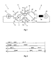
- FIG. 1 is a circuit diagram illustrating a diverter switch of the kind to which the present invention relates.
- the figure shows switching of one phase only and it should be clear that a corresponding diverter switch is arranged for each phase in case of, for example, a three-phase design.
- the diverter switch has a main branch 1 and a resistance branch 2 connected in parallel therewith.
- the main branch 1 comprises a rotary selector contact 11 in series with a vacuum switch 22.
- the resistance branch comprises a resistance contact 21 and a vacuum switch 22.
- the resistance branch 2 also comprises a resistance 30.
- the main contact has a movable contact member 17 which is designed to be rotatable in a counterclockwise direction, as is shown in the embodiment according to Figure 1 , and four fixed contact members 13-16.
- the movable contact member 17 is designed to contact the fixed contact members pairwise to alternate the connection.
- the resistance contact 21 has the same fundamental composition and function.
- the diverter switch In the position shown, the diverter switch is in a position where it connects an output line 5 to a line 3 connected to a tapping point of, for example, a transformer. It may be mentioned here that, in a diverter switch of a three-phase design, the line 5 corresponds to the common neutral point.
- Numeral 4 designates the line to a second tapping point of the transformer. The connections of lines 3 and 4 to the relevant tapping point of the transformer are achieved by a selector (not shown in the figure).
- Line 3 is connected, via a branch 28, to the fixed contact members 13 and 23.
- Line 4 is connected, via a branch 29, to the fixed contact members 16 and 26.
- the output line 5 is connected to that tapping point on the transformer which is connected to the line 4.
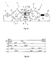
- Figure 2 illustrates the process in a diagram with the x-axis as the time axis.
- the state of each component 11, 12, 21 and 22 during different stages of the process is indicated.
- position 1 means that the fixed contact members 13 and 15 are connected and position 2 means that the fixed contact members 14 and 16 are connected.
- position 1 means that the fixed contact members 23 and 25 are connected and position 2 means that the fixed contact members 24 and 26 are connected.
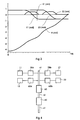
- Figure 3 illustrates the process in a diagram with the x-axis as the time axis and where the circuit breakers and the positions of the rotary selector contacts in relation to the respective initial positions are indicated in centimetres and radians on the y-axis.
- the movement curves of the different components are indicated with the reference numeral of the respective component.
- the movement curve A indicates the rotary motion of an operating shaft which, via movement transfer members, transmits the movement to the respective component.
- Figure 4 is a block diagram schematically illustrating the mechanical operating members that achieve the movement of the components of the diverter switch.
- An input drive member 41 is connected to an intermediate shaft 51 via a movement transformation member 40.
- the drive member 41 is such that, when being operated, it may rotate in one or the other direction.
- the movement transformation member 40 is designed such that a rotary motion is always imparted to the intermediate shaft 51 in one and the same direction independently of in which direction the drive shaft 41 is rotated.
- the movement transformation member 40 illustrated in Figure 4 substantially consists of a system of cooperating gear wheels.
- the energy accumulator 50 substantially consists of a torsion spring of a flat helical spring type.
- the energy accumulator 50 may substantially be in the form of a plurality of flat helical springs connected in parallel with each other.
- the helical spring or springs in the energy accumulator are always tensioned in one and the same direction of rotation, that is, the spring/springs preferably exhibit a predetermined charge direction and discharge direction, respectively, independently of in which direction the drive member 41 rotates.
- the movement transfer members 70a and 70b are substantially in the form of Geneva mechanisms and the movement transfer members 60a and 60b are substantially in the form of cam mechanisms.
- Figure 1a is a circuit diagram illustrating a diverter switch of the kind having a bypass function according to claim 12.
- the diverter switch according to Figure 1a is provided with a bypass branch 200 with a bypass contact 201.
- the bypass contact 201 comprises a movable contact member 202 which at its fixed end is electrically connected to a contact member 203 and at its movable end is alternately connected to the contact members 204 and 205.
- the main part of the load current is passed from the line 3 via the bypass contact 201 through the contact members 204 and 203 to the line 5.
- the vacuum switch 12 is not loaded to any major extent, since the resistance through the bypass contact 201 is lower than the resistance of the vacuum switch.
- Figure 2a illustrates the process in a diagram with the x-axis as the time axis. The state of each component 201, 11, 12, 21 and 22 during different stages of the process is indicated.
- position 1 means that the fixed contact members 203 and 204 are connected and position 2 means that the fixed contact members 203 and 204 are connected.
- position 1 means that the fixed contact members 13 and 15 are connected and position 2 means that the fixed contact members 14 and 16 are connected.
- position 1 means that the fixed contact members 23 and 25 are connected and position 2 means that the fixed contact members 24 and 26 are connected.
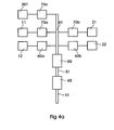
- Figure 4a is a block diagram that schematically illustrates the mechanical operating member that brings about the movement of the components of the diverter switch.
- An input drive member 41 is connected to an intermediate shaft 51 via a movement transformation member 40.
- the drive member 41 is such that, when being operated, it may rotate in one or the other direction.
- the movement transformation member 40 is designed such that a rotary motion is always imparted to the intermediate shaft 51 in one and the same direction independently of in which direction the drive member 41 is rotated.
- the movement transformation member 40 illustrated in Figure 4a substantially consists of a system of cooperating gear wheels as shown in Figure 4 .
- the energy accumulator 50 substantially consists of a torsion spring of a flat helical spring type.
- the energy accumulator 50 may substantially be in the form of a plurality of flat helical springs connected in parallel with each other.
- the helical spring or springs in the energy accumulator are always tensioned in one and the same direction of rotation, that is, the spring/springs preferably exhibit a predetermined charge direction and discharge direction, respectively, independently of in which direction the drive shaft 41a rotates.
- the movement transfer members 70a, 70b and 70c are substantially in the form of Geneva mechanisms and the movement transfer members 60a and 60b are substantially in the form of cam mechanisms.
- FIG. 5 is a schematic longitudinal section through a drive member 41 comprising an input drive shaft 41a and a drive pulley 41b connected thereto, a cylindrical gear wheel 80, a driving pin 41c and a shaft 41d rigidly connected to the gear wheel 80, the movement transformation member 40, the intermediate shaft 51, the energy accumulator 50, and the operating shaft 61.
- the cylindrical gear wheel 80 is in engagement with the drive pulley 41b by means of the driving pin 41c via a recess in the drive pulley 41b.
- the driving pin 41c is thus adapted to transmit rotary motion from the drive shaft 41a to the gear wheel 80.
- the drive pulley 41b constitutes the mechanical interface in the diverter switch housing which is separate from the diverter switch.
- the input drive shaft 41a is thus connected to the intermediate shaft 51 via a number of cylindrical gear wheels, that is, to the shaft that leads to the operation of the diverter switch.
- the gear wheel 80 is rigidly connected to the shaft 41d and in engagement with the gear wheel 81, which in turn is in engagement with the gear wheel 82.
- a ratchet gearing 86 with a pawl 48 the gear wheel 81 is connected to a shaft 42 that is rigidly connected to the gear wheel 83, and by means of a corresponding ratchet gearing 87, the gear wheel 82 is connected to a shaft 43 that is rigidly connected to the gear wheel 84.
- Each ratchet gearing 86, 87 is designed to transmit rotary motion in a clockwise direction from the lower gear wheel to the respective upper wheel and to freewheel, that is, allow relative rotation during a counterclockwise rotary motion of the respective lower gear wheel.
- Each of the two upper gear wheels 83, 84 is in a driving connection with a gear wheel 85 for transmission of rotary motion to the intermediate shaft 51.
- the intermediate shaft 51 is always rotated in one and the same direction independently of whether the input drive shaft is rotated in a clockwise or a counterclockwise direction.
- FIGS 8 and 9 illustrate this manner of operation of the movement transformation member 40.
- the energy accumulator 50 that connects the intermediate shaft 51 to the operating shaft 61 comprises a flat helical spring 52.
- This spring is supported at one end by a holding means (not shown) on a drum 54 rigidly connected to the operating shaft 61.
- the other end of the helical spring makes contact with a carrier element 55 rigidly connected to the intermediate shaft 51.
- a catch 58 is designed to lock the drum 54 and hence also the operating shaft 61 against rotation.
- the catch is designed to be released by means of a release mechanism 59, allowing the drum 54 and the operating shaft to be rotated.
- the carrier element 55 accompanies the shaft in this movement, and, by its contact with the spring 52, it will tension the spring so as to achieve an energy accumulation.
- the release mechanism 59 is designed to release the catch 58 after a predetermined rotary motion, typically smaller than 360°, preferably about 310°.
- the spring mechanism results in a strong time ratio. Whereas the time for rotating the shaft 51 may typically amount to about 5 seconds, the rotation of the operating shaft 61 occurs during a time of approximately 0.2 seconds.
- the movement of the operating shaft 61 is then transmitted via a cam slot 91 to the vacuum switches and a mechanism 71 with pins 72, 73 to the contacts.
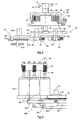
- Figure 6 illustrates the principle of how the rotary motion of the operating shaft 61 is transmitted, via the movement transfer members 60a, 60b, to the respective vacuum switches 12, 22.
- a cam slot 91 is arranged in the drum 54 of the drive shaft 61.
- a cam follower 93 runs in the cam track, and the cam track 91 guides the cam follower 93 in a vertical movement pattern in the figure.
- the cam follower 93 is attached to a rocker arm 100 which is pivotally suspended from a support 101 and is rotatable about an axis perpendicular to the plane of the figure.
- the rocker arm 100 is connected at its other end to a lower yoke 102, which via operating rods 95 is attached to an upper yoke 97.
- the upper yoke is connected via operating rods 96 to the main vacuum switch 12a in the respective phase.
- the operating rods 96 are connected to the upper yoke via a respective spring 99, the point of engagement of which may be adjusted with the aid of a nut 98.
- the operating shaft 61 is provided with a Geneva mechanism 71, rigidly connected thereto, with two axially directed pins 72, 73 for transmitting motion to the rotary selector contacts 11, 21 via the movement transfer members 70a, 70b (see Figure 4 ).
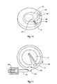
- FIG. 7 shows a perspective view of the two Geneva mechanisms which constitute said movement transfer members 70a, 70b.
- the two pins 72, 73 arranged on the Geneva mechanism 71 are located at a definite angular distance from each other.
- a Geneva wheel 74, 75 On each side is a Geneva wheel 74, 75, arranged to cooperate with the pins.
- the Geneva wheel 74 is rigidly connected, with a shaft (not shown), to the movable contact member 17 in the main contact 11 (see Figure 1 ).
- the pin 73 cooperates with the righthand Geneva wheel 75 for operation of the resistance contact 21.
- the time relationship between the operation of the respective rotary selector contact will be determined by the mechanics of the Geneva mechanisms. For example, a different time relationship may be obtained by selecting a different relative mutual angular position for the pins 72, 73 from what has been shown in Figure 7 .
- FIG 10 illustrates the locking mechanism that corresponds to parts 86, 87 in Figure 5 .
- the outer wheel ring may be assumed to be constituted by the gear wheel 81 which is arranged to transmit a conditioned rotary motion to the shaft 42 that is rigidly connected to the gear wheel 83.
- the wheel 81 is provided with a spring-loaded pawl 48 rotatable about an axis of rotation 49 which is parallel to the intermediate shaft 42.
- a recess 56 In the cylindrical opening of the wheel 81, there is a recess 56 that is large enough to accommodate the pawl when in its depressed position.
- the shaft 42 On that part of the shaft 42 which in the figure is located axially opposite to the pawl 48, the shaft 42 is provided with a radially directed notch 57 that renders the circumferential surface slightly helical.
- the wheel 81 When the wheel 81 is rotated clockwise, the pawl 48 will press against the notch 57, thus forcing the shaft 52 to rotate along with it. If, on the other hand, the wheel 81 is rotated in a counterclockwise direction, the shaft 42 will not be carried along. This causes the pawl 48 to be gradually pressed into the recess 56, and after a completed turn it will again snap up into the shown position.
- the wheel 81 is provided with a leaf spring, which has a function corresponding to that of the spring-loaded pawl.
- the drum 54 (see Fig. 5 ), connected to the driven shaft 61, is provided with a device for braking the rotation of the drum in the end position, that is, after almost one turn, whereby the braking power is transmitted to the rotary element 55 that is connected to the intermediate shaft 51.
- This device is illustrated schematically in Figure 11 , which shows the device immediately before the catch is released to permit rotation of the drum 54.
- the drum 54 is provided with an outer lug 103 arranged on the outside and an inner lug 104 arranged on the inside. In the figure, the outer lug makes contact with the catch 19.
- a brake spring 105 is mounted in the carrier element 55.
- the carrier element 55 exhibits a sector-shaped recess 27, which permits the brake spring 105 to be bent outwards and hence be tensioned.
- the drum 54 causes the carrier element 55 to rotate along with it until 360° has been completed, whereby the outer lug 103 of the drum strikes against the catch 19.
- the catch 19 is provided with a damping spring 106 arranged in a damping unit.
- the damping unit may be formed such that also viscous damping is achieved in connection with the damping spring 106 being activated (compressed).
- the system of gear wheels described with reference to Figures 5 , 8 and 9 may alternatively be replaced by a system of conical gear wheels.
- the drive shaft is provided with a bevel gear wheel with a 45° skew that cooperates with a corresponding bevel gear wheel arranged on the intermediate shaft 51.
- the latter is connected by means of an intermediate conical wheel to a second conical wheel arranged on the intermediate shaft 51.
- the two gear wheels arranged on the intermediate shaft are connected thereto with a ratchet gearing of a kind corresponding to that illustrated in Figure 10 .
Landscapes
- High-Tension Arc-Extinguishing Switches Without Spraying Means (AREA)
- Rotary Switch, Piano Key Switch, And Lever Switch (AREA)
Claims (26)
- Commutateur comprenant un élément d'actionnement et un circuit électrique avec une branche principale (1) et une branche de résistance (2), dans lequel ladite branche principale (1) comprend un contact principal (11) ayant une partie contact mobile (17) et un interrupteur à vide principal (12) et ladite branche de résistance (2) comprend un contact de résistance (21) ayant une partie contact mobile (27), un interrupteur à vide de résistance (22) et une résistance (30), ledit élément d'actionnement étant agencé, pendant l'actionnement, de façon à actionner tout d'abord le contact principal (11), puis le contact de résistance (21), caractérisé en ce que l'élément d'actionnement est agencé, pendant l'actionnement, de façon à toujours tourner au moins la partie contact mobile du contact principal (11) dans un et le même sens de rotation, en ce que l'élément d'actionnement comprend un axe d'actionnement (61), un premier moyen de transfert de mouvement (70a) pour transmettre le mouvement rotatif de l'axe d'actionnement (61) à un axe rotatif du contact principal et un deuxième moyen de transfert de mouvement (70b) pour transmettre le mouvement rotatif de l'axe d'actionnement (61) à un axe rotatif du contact de résistance (21) et en ce que l'élément d'actionnement comprend un élément d'entraînement (41) raccordé, de façon à transmettre l'entraînement, à l'axe d'entraînement (61) par l'intermédiaire de moyens de transfert de mouvement (40, 50) agencés de façon à transformer le mouvement rotatif alternatif de l'élément d'entraînement (41) en un mouvement rotatif unidirectionnel de l'axe d'actionnement (61).
- Commutateur selon la revendication 1, caractérisé en ce que l'élément d'actionnement est agencé, pendant l'actionnement, de façon à toujours tourner la partie contact mobile du contact de résistance (21) dans un et le même sens de rotation.
- Commutateur selon la revendication 2, caractérisé en ce que la partie contact mobile du contact principal (11) et la partie contact mobile du contact de résistance (21) sont agencées de façon à être tournées dans le même sens.
- Commutateur selon la revendication 2, caractérisé en ce que le contact principal (11) et le contact de résistance (21) sont agencés de façon à être tournés dans des sens opposés.
- Commutateur selon la revendication 2, caractérisé en ce que lesdits premier (70a) et deuxième (70b) moyens de transfert de mouvement sont agencés de façon à ce que la rotation de la partie contact mobile du contact à résistance (21) se produise lorsque l'axe d'actionnement (61) a été tourné d'un angle prédéterminé depuis la position dans laquelle la rotation de la partie contact mobile du contact principal (11) se produit.
- Commutateur selon l'une quelconque des revendications 1 à 5, caractérisé en ce qu'au moins un desdits premier et deuxième moyens de transfert de mouvement (70a, 70b) consiste en un mécanisme de Genève.
- Commutateur selon l'une quelconque des revendications 1 à 6, caractérisé en ce que l'élément d'actionnement est agencé de façon à actionner aussi l'interrupteur à vide principal (12) et l'interrupteur à vide de résistance (22).
- Commutateur selon la revendication 7, caractérisé en ce que l'élément d'actionnement comprend un troisième moyen de transfert de mouvement (60a) pour transformer le mouvement rotatif de l'axe d'actionnement en un mouvement d'actionnement pour l'interrupteur à vide principal (12), et un quatrième moyen de transfert de mouvement pour transformer le mouvement rotatif de l'axe d'actionnement (61) en un mouvement d'actionnement pour l'interrupteur à vide de résistance (22).
- Commutateur selon la revendication 8, caractérisé en ce qu'au moins un desdits troisième et quatrième moyens de transfert de mouvement (60a, 60b) consiste en un mécanisme à came.
- Commutateur selon la revendication 8 ou 9, caractérisé en ce que lesdits premier, deuxième, troisième et quatrième moyens de transfert de mouvement (70a, 70b, 60a, 60b) sont agencés de façon à ce que l'actionnement du contact principal (11), du contact de résistance (21), de l'interrupteur à vide principal (12) et de l'interrupteur à vide de résistance (21) se produise dans une séquence prédéterminée et à des angles prédéterminés du mouvement de l'axe d'actionnement (61).
- Commutateur selon la revendication 1, caractérisé en ce que le circuit électrique comprend aussi une branche de dérivation (200) comprenant un contact de dérivation (201) ayant une partie contact mobile, et en ce que l'élément d'actionnement est agencé, pendant l'actionnement, de façon à toujours tourner la partie contact mobile du contact de dérivation (201) dans un et le même sens.
- Commutateur selon la revendication 11, caractérisé en ce que la partie contact mobile du contact de dérivation (201), la partie contact mobile du contact principal (11) et la partie contact mobile du contact de résistance (21) sont agencées de façon à être tournées dans le même sens.
- Commutateur selon la revendication 11, caractérisé en ce que deux parmi la partie contact mobile du contact de dérivation (201), la partie contact mobile du contact principal (11) et la partie contact mobile du contact de résistance (21) sont agencées de façon à être tournées dans un sens opposé à celui du troisième contact.
- Commutateur selon l'une quelconque des revendications 11 à 12, caractérisé en ce que l'élément d'actionnement comprend un axe d'actionnement (61), un premier élément de transfert de mouvement (70a) pour transmettre le mouvement rotation de l'axe d'actionnement (61) à un axe rotatif du contact principal, et un deuxième élément de transfert de mouvement (70b) pour transmettre le mouvement rotatif de l'axe d'actionnement (61) à un axe rotatif du contact de résistance (21), et un cinquième élément de transfert de mouvement (70c) pour transmettre le mouvement rotatif de l'axe d'actionnement (61) à un axe rotatif du contact de dérivation (201).
- Commutateur selon la revendication 14, caractérisé en ce que lesdits premier (70a), deuxième (70b) et troisième (70c) éléments de transfert de mouvement sont agencés de façon à ce que la rotation de la partie contact mobile du contact à résistance (21) se produise lorsque l'axe d'actionnement (61) a été tourné d'un angle prédéterminé depuis la position dans laquelle la rotation de la partie contact mobile du contact principal (11) se produit, et à ce que la rotation du contact principal (11) se produise lorsque l'axe d'actionnement (61) a été tourné d'un angle prédéterminé depuis la position dans laquelle la rotation du contact de dérivation (201) se produit.
- Commutateur selon la revendication 14 ou 15, caractérisé en ce que ledit cinquième moyen de transfert de mouvement (70c) consiste en un mécanisme de Genève.
- Commutateur selon l'une quelconque des revendications 14 ou 15, caractérisé en ce que l'élément d'actionnement est agencé de façon à actionner aussi l'interrupteur à vide principal (12), l'interrupteur à vide de résistance (22), comme quoi l'élément d'actionnement comprend un troisième élément de transfert de mouvement (60a) pour transformer le mouvement rotatif de l'axe d'actionnement en un mouvement d'actionnement pour l'interrupteur à vide principal (12), et un quatrième élément de transfert de mouvement pour transformer le mouvement rotatif de l'axe d'actionnement (61) en un mouvement d'actionnement pour l'interrupteur à vide de résistance (22).
- Commutateur selon la revendication 17, caractérisé en ce que lesdits premier, deuxième, troisième, quatrième et cinquième éléments de transfert de mouvement (70a, 70b, 60a, 60b, 70c) sont agencés de façon à ce que l'actionnement du contact de dérivation (201), du contact principal (11), du contact de résistance (21), de l'interrupteur à vide principal (12) et de l'interrupteur à vide de résistance (21), respectivement, se produise dans une séquence prédéterminée à des angles prédéterminés du mouvement de l'axe d'actionnement (61).
- Commutateur selon la revendication 1, caractérisé en ce que les moyens de transfert de mouvement (40, 50) comprennent un élément d'accumulation d'énergie mécanique (50) agencé de façon à recevoir de l'énergie du mouvement rotatif de l'élément d'entraînement (41) pendant une première période de temps et à fournir de l'énergie à l'axe d'actionnement (61) pendant une deuxième période de temps, ladite deuxième période de temps étant considérablement plus courte que ladite première période de temps.
- Commutateur selon l'une quelconque des revendications 1 à 12, caractérisé en ce que l'élément d'entraînement (41) est raccordé mécaniquement à l'élément de guidage d'un sélecteur coopérant avec le commutateur, ledit élément de guidage étant raccordé à l'élément d'entraînement de façon à ce qu'un mouvement rotatif soit transmis à l'élément d'entraînement (41) dans des sens différents selon que le transformateur est commandé pour fournir une tension plus haute ou plus basse.
- Procédé pour actionner un commutateur, ledit commutateur comprenant un élément d'actionnement et un circuit électrique avec une branche principale et une branche de résistance, dans lequel ladite branche principale comprend un contact principal ayant une partie contact mobile et un interrupteur à vide et dans lequel ladite branche de résistance comprend un contact de résistance ayant une partie contact mobile, un interrupteur à vide de résistance et une résistance, dans lequel, pendant l'actionnement, le contact principal est actionné avant le contact de résistance, caractérisé en ce que, pendant l'actionnement, la partie contact mobile du contact principal est toujours tournée dans un et le même sens de rotation, en ce que l'élément d'actionnement comprend un axe d'actionnement, un premier moyen de transfert de mouvement pour transmettre le mouvement rotatif de l'axe d'actionnement à un axe rotatif du contact principal et un deuxième moyen de transfert de mouvement pour transmettre le mouvement rotatif de l'axe d'actionnement à un axe rotatif du contact de résistance et en ce que l'élément d'actionnement comprend un élément d'entraînement raccordé, de façon à transmettre l'entraînement, à l'axe d'actionnement par l'intermédiaire d'un moyen de transfert de mouvement transformant un mouvement rotatif alternatif de l'élément d'entraînement en un mouvement rotatif unidirectionnel de l'axe d'actionnement.
- Procédé pour actionner un commutateur selon la revendication 21, dans lequel ledit commutateur comprend aussi une branche de dérivation, laquelle branche de dérivation comprend un contact de dérivation, dans lequel, pendant l'actionnement, le contact de dérivation est actionné avant le contact principal, caractérisé en ce que, pendant l'actionnement, la partie contact mobile du contact de dérivation est toujours tournée dans un et le même sens de rotation.
- Procédé selon la revendication 21 ou 22, caractérisé en ce que ce procédé est effectué en utilisant un commutateur selon l'une quelconque des revendications 1 à 20.
- Utilisation d'un commutateur selon l'une quelconque des revendications 1 à 20 pour commander un transformateur.
- Utilisation d'un commutateur selon l'une quelconque des revendications 1 à 20 pour commander une bobine de réactance.
- Utilisation d'un commutateur selon l'une quelconque des revendications 1 à 20 pour commander un condensateur.
Applications Claiming Priority (3)
| Application Number | Priority Date | Filing Date | Title |
|---|---|---|---|
| SE0401713A SE527252C2 (sv) | 2004-06-30 | 2004-06-30 | Lastkopplare, förfarande för manövrering av sådan och användning av sådan |
| SE0500639A SE0500639L (sv) | 2005-03-17 | 2005-03-17 | Lastkopplare, förfarande för manövrering av sådan och användning av sådan |
| PCT/SE2005/001068 WO2006004527A1 (fr) | 2004-06-30 | 2005-06-29 | Commutateur, procede d'actionnement dudit commutateur et utilisation dudit commutateur |
Publications (2)
| Publication Number | Publication Date |
|---|---|
| EP1779397A1 EP1779397A1 (fr) | 2007-05-02 |
| EP1779397B1 true EP1779397B1 (fr) | 2015-12-02 |
Family
ID=35783180
Family Applications (1)
| Application Number | Title | Priority Date | Filing Date |
|---|---|---|---|
| EP05755013.9A Not-in-force EP1779397B1 (fr) | 2004-06-30 | 2005-06-29 | Commutateur, procede d'actionnement dudit commutateur et utilisation dudit commutateur |
Country Status (7)
| Country | Link |
|---|---|
| US (1) | US7982142B2 (fr) |
| EP (1) | EP1779397B1 (fr) |
| JP (1) | JP2008505479A (fr) |
| KR (1) | KR101242828B1 (fr) |
| BR (1) | BRPI0512861A (fr) |
| RU (1) | RU2345437C2 (fr) |
| WO (1) | WO2006004527A1 (fr) |
Families Citing this family (13)
| Publication number | Priority date | Publication date | Assignee | Title |
|---|---|---|---|---|
| SE529799C2 (sv) * | 2005-12-09 | 2007-11-27 | Abb Research Ltd | Anordning för överföring av vridrörelse |
| SE529735C2 (sv) * | 2006-03-28 | 2007-11-06 | Abb Technology Ltd | Sätt och anordning för överföring av vridrörelse |
| DE102009024938A1 (de) * | 2009-06-09 | 2010-12-16 | Siemens Aktiengesellschaft | Schaltgeräteanordnung |
| DE102010007534A1 (de) * | 2010-02-11 | 2011-08-11 | Maschinenfabrik Reinhausen GmbH, 93059 | Stufenschalter |
| DE102010007535B4 (de) * | 2010-02-11 | 2017-12-21 | Maschinenfabrik Reinhausen Gmbh | Stufenschalter mit Freilaufelement |
| DE102010024326A1 (de) * | 2010-06-18 | 2011-12-22 | Maschinenfabrik Reinhausen Gmbh | Stufenschalter |
| DE102010024327B4 (de) * | 2010-06-18 | 2014-12-11 | Maschinenfabrik Reinhausen Gmbh | Stufenschalter |
| DE102010024612B4 (de) * | 2010-06-22 | 2015-06-03 | Maschinenfabrik Reinhausen Gmbh | Stufenschalter |
| DE102010050264A1 (de) * | 2010-11-02 | 2012-05-03 | Maschinenfabrik Reinhausen Gmbh | Mechanischer Schalter für einen Laststufenschalter |
| DE102010050882A1 (de) * | 2010-11-09 | 2012-05-10 | Maschinenfabrik Reinhausen Gmbh | Stufenschalter |
| DE102011013749B4 (de) | 2011-03-12 | 2015-03-19 | Maschinenfabrik Reinhausen Gmbh | Laststufenschalter |
| DE102013107552B4 (de) * | 2013-07-16 | 2017-03-16 | Maschinenfabrik Reinhausen Gmbh | Laststufenschalter |
| WO2019136431A1 (fr) | 2018-01-08 | 2019-07-11 | Janesville Acoustics, a Unit of Jason Incorporated | Ensemble déflecteur à vide |
Citations (3)
| Publication number | Priority date | Publication date | Assignee | Title |
|---|---|---|---|---|
| GB1329867A (en) * | 1969-10-16 | 1973-09-12 | Smit Nijmegen Electrotec | Polyphase on-load tap-changers for regulating transformers |
| DE19510809C1 (de) * | 1995-03-24 | 1996-07-04 | Reinhausen Maschf Scheubeck | Lastumschalter eines Stufenschalters |
| DE19913814C1 (de) * | 1999-03-26 | 2000-04-20 | Reinhausen Maschf Scheubeck | Kraftspeicher für einen Stufenschalter |
Family Cites Families (26)
| Publication number | Priority date | Publication date | Assignee | Title |
|---|---|---|---|---|
| US1497854A (en) | 1922-07-20 | 1924-06-17 | Laval Separator Co De | Milking machine |
| DE1951089A1 (de) | 1969-10-10 | 1971-04-22 | Monforts Fa A | Einrichtung zur Kompensation von Stoergroessen an Lichtschranken |
| DE2731133C2 (de) | 1977-07-09 | 1982-01-07 | Maschinenfabrik Reinhausen Gebrüder Scheubeck GmbH & Co KG, 8400 Regensburg | Stufenschalter für Stufentransformatoren mit einem unter Öl betriebenen Kontaktsystem |
| JPS6245011A (ja) * | 1985-08-22 | 1987-02-27 | Mitsubishi Electric Corp | 負荷時タツプ切換変圧器 |
| JPH0719706B2 (ja) * | 1986-06-26 | 1995-03-06 | 三菱電機株式会社 | 負荷時タツプ切換器の蓄勢機構 |
| JPH0652688B2 (ja) * | 1987-11-11 | 1994-07-06 | 株式会社東芝 | 負荷時タップ切換器 |
| DE3833126C2 (de) * | 1988-09-29 | 1995-11-30 | Reinhausen Maschf Scheubeck | Lastwähler für Stufentransformatoren |
| BR8805485A (pt) | 1988-10-17 | 1990-06-05 | Brasil Compressores Sa | Circuito eletronico de controle para motor de corrente continua sem escovas |
| DE4315060A1 (de) | 1992-07-16 | 1994-11-10 | Reinhausen Maschf Scheubeck | Lastwähler für Stufenschalter an Stufentransformatoren |
| RO112973B1 (ro) | 1992-07-16 | 1998-02-27 | Reinhausen Maschf Scheubeck | Comutator in trepte |
| JP2719289B2 (ja) * | 1992-10-29 | 1998-02-25 | 三菱電機株式会社 | 負荷時タップ切換器のタップ選択器駆動用1タップ遊び接手 |
| JP2844515B2 (ja) * | 1993-12-27 | 1999-01-06 | 株式会社高岳製作所 | 負荷時タップ切換器 |
| AU2067895A (en) * | 1994-03-09 | 1995-09-25 | Maschinenfabrik Reinhausen Gmbh | Switching arrangement for load change-over switches of step switches and for selector switches |
| DE4439813C1 (de) | 1994-11-08 | 1996-06-20 | Reinhausen Maschf Scheubeck | Stufenschalter und Verfahren zu dessen Überwachung |
| DE19501529C1 (de) * | 1995-01-19 | 1996-06-20 | Reinhausen Maschf Scheubeck | Umschaltanordnung |
| US5693922A (en) * | 1995-11-13 | 1997-12-02 | Abb Power T&D Company Inc. | Diverter switch and link system for load tap changer |
| DE29622685U1 (de) | 1996-05-02 | 1997-09-04 | Maschinenfabrik Reinhausen Gmbh, 93059 Regensburg | Stufenschalter |
| JP3836547B2 (ja) * | 1996-10-15 | 2006-10-25 | 株式会社東芝 | 負荷時タップ切換器 |
| JP3851715B2 (ja) * | 1997-09-25 | 2006-11-29 | 東芝変電機器テクノロジー株式会社 | 負荷時タップ切換器 |
| DE19821775C1 (de) * | 1998-05-14 | 1999-10-14 | Reinhausen Maschf Scheubeck | Lastwähler |
| DE19847745C1 (de) | 1998-10-16 | 2000-01-05 | Reinhausen Maschf Scheubeck | Stufenschalter |
| US6492608B1 (en) * | 1999-04-06 | 2002-12-10 | Bing Sun | Microswitch with shifting gear |
| DE10050895C1 (de) | 2000-10-13 | 2002-08-08 | Reinhausen Maschf Scheubeck | Lastumschalter für einen Stufenschalter |
| DE10050821C1 (de) | 2000-10-13 | 2002-05-02 | Reinhausen Maschf Scheubeck | Mechanischer Schaltkontakt |
| JP2003233459A (ja) * | 2002-02-06 | 2003-08-22 | Seiko Epson Corp | 発電機付入力装置 |
| JP2005032450A (ja) * | 2003-07-07 | 2005-02-03 | Matsushita Electric Ind Co Ltd | スイッチ装置 |
-
2005
- 2005-06-29 KR KR1020077002306A patent/KR101242828B1/ko active IP Right Grant
- 2005-06-29 BR BRPI0512861-7A patent/BRPI0512861A/pt not_active IP Right Cessation
- 2005-06-29 US US11/630,768 patent/US7982142B2/en not_active Expired - Fee Related
- 2005-06-29 RU RU2007103345/09A patent/RU2345437C2/ru not_active IP Right Cessation
- 2005-06-29 EP EP05755013.9A patent/EP1779397B1/fr not_active Not-in-force
- 2005-06-29 WO PCT/SE2005/001068 patent/WO2006004527A1/fr active Application Filing
- 2005-06-29 JP JP2007519169A patent/JP2008505479A/ja active Pending
Patent Citations (3)
| Publication number | Priority date | Publication date | Assignee | Title |
|---|---|---|---|---|
| GB1329867A (en) * | 1969-10-16 | 1973-09-12 | Smit Nijmegen Electrotec | Polyphase on-load tap-changers for regulating transformers |
| DE19510809C1 (de) * | 1995-03-24 | 1996-07-04 | Reinhausen Maschf Scheubeck | Lastumschalter eines Stufenschalters |
| DE19913814C1 (de) * | 1999-03-26 | 2000-04-20 | Reinhausen Maschf Scheubeck | Kraftspeicher für einen Stufenschalter |
Also Published As
| Publication number | Publication date |
|---|---|
| KR101242828B1 (ko) | 2013-03-12 |
| US20080257703A1 (en) | 2008-10-23 |
| JP2008505479A (ja) | 2008-02-21 |
| RU2345437C2 (ru) | 2009-01-27 |
| EP1779397A1 (fr) | 2007-05-02 |
| WO2006004527A1 (fr) | 2006-01-12 |
| KR20070027757A (ko) | 2007-03-09 |
| US7982142B2 (en) | 2011-07-19 |
| RU2007103345A (ru) | 2008-08-10 |
| BRPI0512861A (pt) | 2008-04-08 |
Similar Documents
| Publication | Publication Date | Title |
|---|---|---|
| EP1779397B1 (fr) | Commutateur, procede d'actionnement dudit commutateur et utilisation dudit commutateur | |
| EP2689440B1 (fr) | Preselecteur pour un commutateur de prises en charge | |
| EP3553805B1 (fr) | Mécanisme automatique d'un commutateur à double alimentation | |
| CN102129922A (zh) | 开闭器用操作装置 | |
| CA1118826A (fr) | Commutateur de repositionnement des prises sur transformateur-regulateur | |
| US9127751B2 (en) | Gearbox for a tap changer, a tap changer and a transformer | |
| KR100515886B1 (ko) | 시퀀스 스위치용 에너지 저장기 | |
| CN101326602B (zh) | 用于传递旋转运动的设备及其应用 | |
| CN100495605C (zh) | 转换开关、这样的开关的操作方法及用途 | |
| US3155782A (en) | Switch actuating mechanism for controlled speed tap changer | |
| CN107221463B (zh) | 一种真空有载分接开关 | |
| CN102067259B (zh) | 用于开关设备的控制器单元 | |
| JP2021515386A (ja) | 負荷時タップ切換器、および、負荷時タップ切換器を有するローカルネットワーク変圧器 | |
| KR101753107B1 (ko) | 초고압 차단기용 개폐장치 | |
| EP2535910A1 (fr) | Accumulateur d'énergie pour actionner un dispositif de commutation, changeur de prise et transformateur | |
| JP2004023026A (ja) | 真空バルブ式負荷時タップ切換装置 | |
| KR20230080503A (ko) | 부하시 탭 절환기용의 스위칭 시스템, 부하시 탭 절환기 및 부하시 탭 절환기의 탭 연결의 스위칭 방법 | |
| AU2020381819A1 (en) | On-load tap changer | |
| EP2591484A1 (fr) | Procédé et système pour un présélecteur dans un changeur de prise | |
| CN203312051U (zh) | 用于分接开关中的预选器的预选器致动装置 | |
| US3852553A (en) | Vacuum switch with toggle assembly operating mechanism | |
| EP2093780B1 (fr) | Unité de commande de ressort, dispositif de commande pour appareil de commutation électrique et procédé de chargement et/ou déchargement d'un ressort dans un dispositif de fonctionnement pour un appareil de commutation électrique | |
| SU951441A1 (ru) | Электродвигательный привод дл переключателей | |
| EP1156502A1 (fr) | Actionneur d'interrupteur a coupure en charge | |
| KR20230138014A (ko) | 온-로드 탭 체인저를 위한 구동 시스템 |
Legal Events
| Date | Code | Title | Description |
|---|---|---|---|
| PUAI | Public reference made under article 153(3) epc to a published international application that has entered the european phase |
Free format text: ORIGINAL CODE: 0009012 |
|
| 17P | Request for examination filed |
Effective date: 20070126 |
|
| AK | Designated contracting states |
Kind code of ref document: A1 Designated state(s): AT BE BG CH CY CZ DE DK EE ES FI FR GB GR HU IE IS IT LI LT LU MC NL PL PT RO SE SI SK TR |
|
| RIN1 | Information on inventor provided before grant (corrected) |
Inventor name: VALDEMARSSON, STEFAN Inventor name: NILSSON, PETTER Inventor name: LARSSON, TOMMY Inventor name: JONSSON, LARS |
|
| DAX | Request for extension of the european patent (deleted) | ||
| 17Q | First examination report despatched |
Effective date: 20130724 |
|
| GRAP | Despatch of communication of intention to grant a patent |
Free format text: ORIGINAL CODE: EPIDOSNIGR1 |
|
| INTG | Intention to grant announced |
Effective date: 20150629 |
|
| GRAS | Grant fee paid |
Free format text: ORIGINAL CODE: EPIDOSNIGR3 |
|
| GRAA | (expected) grant |
Free format text: ORIGINAL CODE: 0009210 |
|
| AK | Designated contracting states |
Kind code of ref document: B1 Designated state(s): AT BE BG CH CY CZ DE DK EE ES FI FR GB GR HU IE IS IT LI LT LU MC NL PL PT RO SE SI SK TR |
|
| REG | Reference to a national code |
Ref country code: GB Ref legal event code: FG4D |
|
| REG | Reference to a national code |
Ref country code: AT Ref legal event code: REF Ref document number: 763953 Country of ref document: AT Kind code of ref document: T Effective date: 20151215 Ref country code: CH Ref legal event code: EP |
|
| REG | Reference to a national code |
Ref country code: IE Ref legal event code: FG4D |
|
| REG | Reference to a national code |
Ref country code: DE Ref legal event code: R096 Ref document number: 602005048009 Country of ref document: DE |
|
| REG | Reference to a national code |
Ref country code: NL Ref legal event code: MP Effective date: 20160302 |
|
| REG | Reference to a national code |
Ref country code: LT Ref legal event code: MG4D |
|
| REG | Reference to a national code |
Ref country code: AT Ref legal event code: MK05 Ref document number: 763953 Country of ref document: AT Kind code of ref document: T Effective date: 20151202 |
|
| PG25 | Lapsed in a contracting state [announced via postgrant information from national office to epo] |
Ref country code: LT Free format text: LAPSE BECAUSE OF FAILURE TO SUBMIT A TRANSLATION OF THE DESCRIPTION OR TO PAY THE FEE WITHIN THE PRESCRIBED TIME-LIMIT Effective date: 20151202 Ref country code: ES Free format text: LAPSE BECAUSE OF FAILURE TO SUBMIT A TRANSLATION OF THE DESCRIPTION OR TO PAY THE FEE WITHIN THE PRESCRIBED TIME-LIMIT Effective date: 20151202 |
|
| PG25 | Lapsed in a contracting state [announced via postgrant information from national office to epo] |
Ref country code: FI Free format text: LAPSE BECAUSE OF FAILURE TO SUBMIT A TRANSLATION OF THE DESCRIPTION OR TO PAY THE FEE WITHIN THE PRESCRIBED TIME-LIMIT Effective date: 20151202 Ref country code: PL Free format text: LAPSE BECAUSE OF FAILURE TO SUBMIT A TRANSLATION OF THE DESCRIPTION OR TO PAY THE FEE WITHIN THE PRESCRIBED TIME-LIMIT Effective date: 20151202 Ref country code: NL Free format text: LAPSE BECAUSE OF FAILURE TO SUBMIT A TRANSLATION OF THE DESCRIPTION OR TO PAY THE FEE WITHIN THE PRESCRIBED TIME-LIMIT Effective date: 20151202 Ref country code: AT Free format text: LAPSE BECAUSE OF FAILURE TO SUBMIT A TRANSLATION OF THE DESCRIPTION OR TO PAY THE FEE WITHIN THE PRESCRIBED TIME-LIMIT Effective date: 20151202 Ref country code: SE Free format text: LAPSE BECAUSE OF FAILURE TO SUBMIT A TRANSLATION OF THE DESCRIPTION OR TO PAY THE FEE WITHIN THE PRESCRIBED TIME-LIMIT Effective date: 20151202 Ref country code: GR Free format text: LAPSE BECAUSE OF FAILURE TO SUBMIT A TRANSLATION OF THE DESCRIPTION OR TO PAY THE FEE WITHIN THE PRESCRIBED TIME-LIMIT Effective date: 20160303 |
|
| PG25 | Lapsed in a contracting state [announced via postgrant information from national office to epo] |
Ref country code: IS Free format text: LAPSE BECAUSE OF FAILURE TO SUBMIT A TRANSLATION OF THE DESCRIPTION OR TO PAY THE FEE WITHIN THE PRESCRIBED TIME-LIMIT Effective date: 20151202 |
|
| PG25 | Lapsed in a contracting state [announced via postgrant information from national office to epo] |
Ref country code: CZ Free format text: LAPSE BECAUSE OF FAILURE TO SUBMIT A TRANSLATION OF THE DESCRIPTION OR TO PAY THE FEE WITHIN THE PRESCRIBED TIME-LIMIT Effective date: 20151202 Ref country code: IT Free format text: LAPSE BECAUSE OF FAILURE TO SUBMIT A TRANSLATION OF THE DESCRIPTION OR TO PAY THE FEE WITHIN THE PRESCRIBED TIME-LIMIT Effective date: 20151202 |
|
| PG25 | Lapsed in a contracting state [announced via postgrant information from national office to epo] |
Ref country code: RO Free format text: LAPSE BECAUSE OF FAILURE TO SUBMIT A TRANSLATION OF THE DESCRIPTION OR TO PAY THE FEE WITHIN THE PRESCRIBED TIME-LIMIT Effective date: 20151202 Ref country code: IS Free format text: LAPSE BECAUSE OF FAILURE TO SUBMIT A TRANSLATION OF THE DESCRIPTION OR TO PAY THE FEE WITHIN THE PRESCRIBED TIME-LIMIT Effective date: 20160402 Ref country code: PT Free format text: LAPSE BECAUSE OF FAILURE TO SUBMIT A TRANSLATION OF THE DESCRIPTION OR TO PAY THE FEE WITHIN THE PRESCRIBED TIME-LIMIT Effective date: 20160404 Ref country code: SK Free format text: LAPSE BECAUSE OF FAILURE TO SUBMIT A TRANSLATION OF THE DESCRIPTION OR TO PAY THE FEE WITHIN THE PRESCRIBED TIME-LIMIT Effective date: 20151202 Ref country code: EE Free format text: LAPSE BECAUSE OF FAILURE TO SUBMIT A TRANSLATION OF THE DESCRIPTION OR TO PAY THE FEE WITHIN THE PRESCRIBED TIME-LIMIT Effective date: 20151202 |
|
| REG | Reference to a national code |
Ref country code: DE Ref legal event code: R097 Ref document number: 602005048009 Country of ref document: DE |
|
| PLBE | No opposition filed within time limit |
Free format text: ORIGINAL CODE: 0009261 |
|
| STAA | Information on the status of an ep patent application or granted ep patent |
Free format text: STATUS: NO OPPOSITION FILED WITHIN TIME LIMIT |
|
| PG25 | Lapsed in a contracting state [announced via postgrant information from national office to epo] |
Ref country code: DK Free format text: LAPSE BECAUSE OF FAILURE TO SUBMIT A TRANSLATION OF THE DESCRIPTION OR TO PAY THE FEE WITHIN THE PRESCRIBED TIME-LIMIT Effective date: 20151202 |
|
| 26N | No opposition filed |
Effective date: 20160905 |
|
| PG25 | Lapsed in a contracting state [announced via postgrant information from national office to epo] |
Ref country code: SI Free format text: LAPSE BECAUSE OF FAILURE TO SUBMIT A TRANSLATION OF THE DESCRIPTION OR TO PAY THE FEE WITHIN THE PRESCRIBED TIME-LIMIT Effective date: 20151202 |
|
| PG25 | Lapsed in a contracting state [announced via postgrant information from national office to epo] |
Ref country code: BE Free format text: LAPSE BECAUSE OF FAILURE TO SUBMIT A TRANSLATION OF THE DESCRIPTION OR TO PAY THE FEE WITHIN THE PRESCRIBED TIME-LIMIT Effective date: 20151202 |
|
| PG25 | Lapsed in a contracting state [announced via postgrant information from national office to epo] |
Ref country code: MC Free format text: LAPSE BECAUSE OF FAILURE TO SUBMIT A TRANSLATION OF THE DESCRIPTION OR TO PAY THE FEE WITHIN THE PRESCRIBED TIME-LIMIT Effective date: 20151202 |
|
| REG | Reference to a national code |
Ref country code: CH Ref legal event code: PL |
|
| GBPC | Gb: european patent ceased through non-payment of renewal fee |
Effective date: 20160629 |
|
| REG | Reference to a national code |
Ref country code: IE Ref legal event code: MM4A |
|
| REG | Reference to a national code |
Ref country code: FR Ref legal event code: ST Effective date: 20170228 |
|
| PG25 | Lapsed in a contracting state [announced via postgrant information from national office to epo] |
Ref country code: LI Free format text: LAPSE BECAUSE OF NON-PAYMENT OF DUE FEES Effective date: 20160630 Ref country code: FR Free format text: LAPSE BECAUSE OF NON-PAYMENT OF DUE FEES Effective date: 20160630 Ref country code: CH Free format text: LAPSE BECAUSE OF NON-PAYMENT OF DUE FEES Effective date: 20160630 |
|
| PG25 | Lapsed in a contracting state [announced via postgrant information from national office to epo] |
Ref country code: IE Free format text: LAPSE BECAUSE OF NON-PAYMENT OF DUE FEES Effective date: 20160629 Ref country code: GB Free format text: LAPSE BECAUSE OF NON-PAYMENT OF DUE FEES Effective date: 20160629 |
|
| PG25 | Lapsed in a contracting state [announced via postgrant information from national office to epo] |
Ref country code: CY Free format text: LAPSE BECAUSE OF FAILURE TO SUBMIT A TRANSLATION OF THE DESCRIPTION OR TO PAY THE FEE WITHIN THE PRESCRIBED TIME-LIMIT Effective date: 20151202 Ref country code: HU Free format text: LAPSE BECAUSE OF FAILURE TO SUBMIT A TRANSLATION OF THE DESCRIPTION OR TO PAY THE FEE WITHIN THE PRESCRIBED TIME-LIMIT; INVALID AB INITIO Effective date: 20050629 |
|
| PG25 | Lapsed in a contracting state [announced via postgrant information from national office to epo] |
Ref country code: TR Free format text: LAPSE BECAUSE OF FAILURE TO SUBMIT A TRANSLATION OF THE DESCRIPTION OR TO PAY THE FEE WITHIN THE PRESCRIBED TIME-LIMIT Effective date: 20151202 Ref country code: LU Free format text: LAPSE BECAUSE OF NON-PAYMENT OF DUE FEES Effective date: 20160629 |
|
| REG | Reference to a national code |
Ref country code: DE Ref legal event code: R081 Ref document number: 602005048009 Country of ref document: DE Owner name: ABB SCHWEIZ AG, CH Free format text: FORMER OWNER: ABB RESEARCH LTD., ZUERICH, CH Ref country code: DE Ref legal event code: R081 Ref document number: 602005048009 Country of ref document: DE Owner name: ABB POWER GRIDS SWITZERLAND AG, CH Free format text: FORMER OWNER: ABB RESEARCH LTD., ZUERICH, CH |
|
| REG | Reference to a national code |
Ref country code: DE Ref legal event code: R081 Ref document number: 602005048009 Country of ref document: DE Owner name: ABB POWER GRIDS SWITZERLAND AG, CH Free format text: FORMER OWNER: ABB SCHWEIZ AG, BADEN, CH |
|
| PGFP | Annual fee paid to national office [announced via postgrant information from national office to epo] |
Ref country code: DE Payment date: 20210618 Year of fee payment: 17 |
|
| PGFP | Annual fee paid to national office [announced via postgrant information from national office to epo] |
Ref country code: BG Payment date: 20210618 Year of fee payment: 17 |
|
| REG | Reference to a national code |
Ref country code: DE Ref legal event code: R119 Ref document number: 602005048009 Country of ref document: DE |
|
| PG25 | Lapsed in a contracting state [announced via postgrant information from national office to epo] |
Ref country code: DE Free format text: LAPSE BECAUSE OF NON-PAYMENT OF DUE FEES Effective date: 20230103 |
|
| PG25 | Lapsed in a contracting state [announced via postgrant information from national office to epo] |
Ref country code: BG Free format text: LAPSE BECAUSE OF NON-PAYMENT OF DUE FEES Effective date: 20220629 |