EP1156502A1 - Actionneur d'interrupteur a coupure en charge - Google Patents
Actionneur d'interrupteur a coupure en charge Download PDFInfo
- Publication number
- EP1156502A1 EP1156502A1 EP00937248A EP00937248A EP1156502A1 EP 1156502 A1 EP1156502 A1 EP 1156502A1 EP 00937248 A EP00937248 A EP 00937248A EP 00937248 A EP00937248 A EP 00937248A EP 1156502 A1 EP1156502 A1 EP 1156502A1
- Authority
- EP
- European Patent Office
- Prior art keywords
- cylindrical roller
- shaft
- output shaft
- rotating lever
- contact
- Prior art date
- Legal status (The legal status is an assumption and is not a legal conclusion. Google has not performed a legal analysis and makes no representation as to the accuracy of the status listed.)
- Withdrawn
Links
Images


Classifications
-
- H—ELECTRICITY
- H02—GENERATION; CONVERSION OR DISTRIBUTION OF ELECTRIC POWER
- H02B—BOARDS, SUBSTATIONS OR SWITCHING ARRANGEMENTS FOR THE SUPPLY OR DISTRIBUTION OF ELECTRIC POWER
- H02B13/00—Arrangement of switchgear in which switches are enclosed in, or structurally associated with, a casing, e.g. cubicle
-
- H—ELECTRICITY
- H01—ELECTRIC ELEMENTS
- H01H—ELECTRIC SWITCHES; RELAYS; SELECTORS; EMERGENCY PROTECTIVE DEVICES
- H01H3/00—Mechanisms for operating contacts
- H01H3/32—Driving mechanisms, i.e. for transmitting driving force to the contacts
- H01H3/42—Driving mechanisms, i.e. for transmitting driving force to the contacts using cam or eccentric
-
- H—ELECTRICITY
- H01—ELECTRIC ELEMENTS
- H01H—ELECTRIC SWITCHES; RELAYS; SELECTORS; EMERGENCY PROTECTIVE DEVICES
- H01H3/00—Mechanisms for operating contacts
- H01H3/22—Power arrangements internal to the switch for operating the driving mechanism
-
- H—ELECTRICITY
- H01—ELECTRIC ELEMENTS
- H01H—ELECTRIC SWITCHES; RELAYS; SELECTORS; EMERGENCY PROTECTIVE DEVICES
- H01H3/00—Mechanisms for operating contacts
- H01H3/22—Power arrangements internal to the switch for operating the driving mechanism
- H01H3/26—Power arrangements internal to the switch for operating the driving mechanism using dynamo-electric motor
-
- H—ELECTRICITY
- H01—ELECTRIC ELEMENTS
- H01H—ELECTRIC SWITCHES; RELAYS; SELECTORS; EMERGENCY PROTECTIVE DEVICES
- H01H3/00—Mechanisms for operating contacts
- H01H3/32—Driving mechanisms, i.e. for transmitting driving force to the contacts
-
- H—ELECTRICITY
- H01—ELECTRIC ELEMENTS
- H01H—ELECTRIC SWITCHES; RELAYS; SELECTORS; EMERGENCY PROTECTIVE DEVICES
- H01H3/00—Mechanisms for operating contacts
- H01H3/32—Driving mechanisms, i.e. for transmitting driving force to the contacts
- H01H3/40—Driving mechanisms, i.e. for transmitting driving force to the contacts using friction, toothed, or screw-and-nut gearing
- H01H2003/405—Driving mechanisms, i.e. for transmitting driving force to the contacts using friction, toothed, or screw-and-nut gearing using a walking nut
Definitions
- This invention relates to an operating apparatus for an electric power load break switch such as a disconnect switch or a grounding switch.
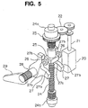
- Figure 5 shows the state in which the contacts (not shown) of an operating mechanism in a conventional electric power load break switch are open
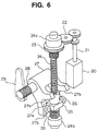
- Figure 6 shows the state in which the contacts are closed.
- 20 is a drive mechanism which can be driven by an electric motor or manually
- 21 is a drive shaft of the drive mechanism 20.
- the torque of the drive shaft 21 is transmitted to a spur gear 23 by a spur gear 22.
- 24 is an input shaft in the form of a shaft with a trapezoidal thread. It is supported by bearings 24a and 24b at both end portions, and spur gear 23 is secured to one end portion.
- a nut 25 with a trapezoidal thread having a roughly rectangular outer shape is threaded onto the trapezoidal thread shaft 24.
- Rollers 26 are mounted on both side surfaces of the trapezoidal thread nut 25 so as to be orthogonal to the trapezoidal thread shaft 24.
- a V-shaped lever 27 having at both side portions a portion joined to one of the rollers 26 and formed into roughly the shape of a V by a curved portion 27a and two straight portions 27b is secured to an output shaft 28 which is parallel to the rollers 26.
- An operating member 29 (shown by the double dot chain line in Figures 5 and 6) is secured to one end of the output shaft 28. The operating member 29 performs switching operation of an unillustrated contact mechanism, and it opens and closes an electric circuit.
- Stop control of the electric motor which forms the drive source of the drive mechanism 20 is performed by detecting the rotational position of the operating member 29 after the completion of switching of the unillustrated contacts.
- the electric motor performs a few rotations due to inertia after stopping operation. This phenomenon is the same in either forward or reverse, i.e., in both the direction performing closing operation or the direction performing opening operation of the contacts. Due to this rotation, the rollers 26 perform extra linear movement by this amount. However, it is necessary for the stopped position of the contacts not to change as a result of this.
- the linear portions 27b are formed on both sides of the curved portions 27a of the V-shaped lever 27 so that even if the rollers 26 continue linear movement in either the forward or reverse direction, the V-shaped lever 27 does not rotate and is fixed in a prescribed position.
- the length of the trapezoidal thread shaft 24 is insufficient for the length of the trapezoidal thread shaft 24 to be only a length necessary to drive the V-shaped lever 27, and it must be lengthened by an amount by which the rollers 26 perform linear movement while the rollers 26 contact the linear portions 27b.
- the bearings 24a and 24b for the shaft 24 are disposed and secured outside the drive region of the rollers 26.
- V-shaped lever 27 contacts the rollers 26 and performs rotational movement due to the rollers 26, since it has a cantilever structure, bending stresses are generated, and the base portions of the V-shaped lever 27 must have a stiffness which can withstand the bending stresses which are generated. Therefore, it was necessary for the V-shaped lever 27 to have a somewhat large shape or to have its strength increased by heat treatment or the like. Furthermore, when the V-shaped lever 27 is made large, the range of its operation increases, and there was the problem that further free space was necessary in order to guarantee its operating range.
- This invention was made in order to solve problems like those described above. Its object is to provide an operating apparatus for an electric power load break switch which renders unnecessary a trapezoidal thread screw and a V-shaped lever, which require wasted space and bending stiffness, and which increases the efficiency of power transmission and seeks decrease in size.
- the present invention is one having a drive mechanism with a drive source in the form of an electric motor, a drive shaft, and the like, an input shaft which transmits rotational drive force from the drive mechanism, an input spur gear which is secured to the input shaft and which rotates with the input shaft, a cylindrical roller which has a shaft center which is spaced from the input shaft and is parallel to the input shaft and which projects from the side surface of the input spur gear and which is formed so as to revolve about the input shaft due to rotation of the input spur gear, an output shaft which is disposed so as to be parallel to the input shaft and the cylindrical roller, a rotating lever which has at one end a cam hole which is in contact with the side surface of the cylindrical roller and which has another end through which the output shaft passes and which is secured to the output shaft and rotates as a single member with the output shaft, and an operating member which operates a contact mechanism by the torque of the output shaft, wherein the end surface of the cam hole of the rotating lever has two cam surface portions for forward and reverse rotation
- the cam hole is formed so that the two recessed curved surface portions for forward and reverse rotation are joined to each other at their ends.
- an electric power load break switch constituted as described above, rotational movement from the drive shaft is transmitted to the operating member secured to the output shaft as rotational movement through the input spur gear, the cylindrical roller, and the rotating lever without being converted to linear movement.
- an electric power load break switch according to this invention does not need a large-diameter trapezoidal thread screw which requires wasted space and bending stiffness, and additionally, the transmission efficiency is increased, so the input force is decreased.
- the rotating lever which transmits rotational movement to the operating member which operates the contact mechanism has a cam hole, and it does not need a conventional roughly V-shaped member.
- the shape of the cam hole is such as to be closed at the ends thereof, the section modulus of the rotating lever with respect to bending at the time of contacting the cylindrical roller can be increased, and the stiffness of the rotating lever can be increased, so the rotating lever can be made compact.
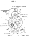
- 1 is a drive mechanism which is constituted so as to be capable of being driven by an electric motor and manually. As shown in Figure 3, it is secured to one side (the left side in Figure 3) of two support plates 11 and 12 which are perpendicular to a casing 13 and parallel to each other.
- This drive mechanism 1 has a manual operating shaft 1 a and a drive shaft 1b. Torque from the drive shaft 1b of the drive mechanism 1 is transmitted to an input spur gear 3, which is secured to an input shaft 4, through an intermediate transmission mechanism made from intermediate spur gears 2a, 2b, 2c, and the like and disposed between the two support plates 11 and 12.
- the input spur gear 3 is selectively rotated forwards or in reverse in direction A or B (see Figure 1).
- the input shaft 4 is mounted on the casing 13 by suitable means.
- a cylindrical roller 5 is mounted on the side surface portion of the input spur gear 3.
- the shaft center of the cylindrical roller 5 is parallel to the shaft center of the input shaft 4.
- 6 is an output shaft which is parallel to and spaced from the input shaft 4 and the cylindrical roller 5.
- the output shaft 6 is supported by bearings 6a and 6b mounted on the casing 13.
- a rotating lever 7 is secured to the output shaft 6.
- the rotating lever 7 has roughly the shape of the sole of a shoe.
- a roughly gourd-shaped cam hole 8 which is in line contact with the side surface of the cylindrical roller 5 is formed in the end side portion (the opposite side from the output shaft 6) of the rotating lever 7.
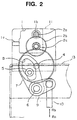
- the cam hole 8 is for the purpose of transmitting the torque of the input spur gear 3 to the output shaft 6 through the cylindrical roller 5. This point will be described more concretely.
- the electric motor within the drive mechanism 1 is stopped when the cylindrical roller 5 rotates to angular position B 2 (A 0 ), but the electric motor further rotates due to inertia, so the cylindrical roller 5 further rotates in direction B.
- Recessed surface portion Fb of the cam hole 8 has a curved surface which coincides with the path of rotation of the cylindrical roller 5 so that at this time, the output shaft 6 will not further rotate in direction b due to the rotation of the cylindrical roller 5.
- play surface portion Nb is formed so that the side surface of the cylindrical roller 5 will not interfere with the cam hole 8.
- This play surface portion Nb is formed so that a roughly elliptical space which is slightly larger than the diameter of the cylindrical roller 5 is formed.
- the end portion of the cam hole 8 between recessed surface portion Fa and recessed surface portion Fb extends recessed surface portion Fa and recessed surface portion Fb and joins them, and it is a play surface portion Nt which is formed with a shape which closes the cam hole 8.
- operating members 9 which are formed as levers for operating unillustrated contact mechanisms are secured to the output shaft 6.
- a rod 10 which converts the rotational movement of one of the operating members 9 into linear movement and transmits it to a contact mechanism is rotatably supported at the end portion of each operating member 9.
- direction A is the rotational direction of the input spur gear 3 when the unillustrated contacts are closed.
- direction B is the rotational direction of the input spur gear 3 when the unillustrated contacts are opened.
- stop control of the electric motor within the drive mechanism 1 is carried out by an unillustrated limit switch, but the electric motor rotates several times due to inertia.
- the cylindrical roller 5 further rotates, but as described above, the side surface of the cylindrical roller 5 is contacting recessed surface portion Fa of the cam hole 8, so the rotating lever 7 does not further rotate, and the contacts of the unillustrated electric power load break switch are maintained with certainty in a closed state.
- stop control of the electric motor within the drive mechanism 1 is carried out by an unillustrated limit switch, but the electric motor performs several rotations due to inertia.
- the cylindrical roller 5 further rotates, but the side surface of the cylindrical roller 5 contacts recessed surface portion Fb of the cam hole 8, so the rotating lever 7 does not further rotate, and the contacts of the unillustrated electric power load break switch are maintained with certainty in an open position.
- a contact mechanism for an electric power load break switch which is operated by the operating members 9 and the rods 10
- one which is of the type in which contacts are disposed inside a vacuum chamber and elastic force from a spring is utilized as force for maintaining the contacts in a closed state may be used.
- the contacts are maintained inside a vacuum chamber, so a self-closing force (namely, a force for closing on its own) acts when the contacts are open. Accordingly, in this case, the self-closing force acts on the operating members 9.
- the structure is such that the self-closing force is overcome and the contacts are maintained with certainty in an open state. While operating the contacts from an open state to a closed state, the torque for rotating the rotating lever 7 can be decreased by the amount of the self-closing force.
- one in which blade-type contacts are disposed in air or in a gas may be used as the contact mechanism for the electric power load break switch.
- the contact mechanism for the electric power load break switch in order to press in the blade-type contacts, it is sufficient to have a force which can just overcome the frictional force necessary to dose the blade-type contacts, so the drive force of the drive mechanism 1 can be decreased. Accordingly, the cylindrical roller 5 and the rotating lever 7 can be made more compact, and the operating apparatus for the electric power load break switch can be made more compact.
- This invention is constituted as described above, so effects like those described below can be provided.
- rotational movement from a drive mechanism can be transmitted as such to an operating member which operates a contact mechanism of an electric power load break switch by an input spur gear, a rotating lever, etc., and a member which converts rotational movement to linear movement is not used, so a trapezoidal thread screw which is conventionally used and which requires wasted space and a large bending stiffness is not necessary. Accordingly, the transmission efficiency is increased, the input force is decreased, the electric motor may be a small one with a low output force, and the force during manual operation can also be decreased.
- the shape of the rotating lever is not that of a V but is one having a closed cam hole, so it can have a large section modulus to resist bending stresses generated by contact between the cylindrical roller and the cam surfaces. Accordingly, it can have a higher stiffness and be made more compact than a conventional V-shaped lever.
- the operating range of the rotating lever is smaller than that of a conventional V-shaped lever, so the space required by the operating mechanism for an electric power load break switch can be decreased.
- an operating mechanism for an electric power load break switch can be used in large disconnect switches or grounding switches at transformer substations and the like as one which does not require a motor with a large output force or a large manual force.
Landscapes
- Engineering & Computer Science (AREA)
- Power Engineering (AREA)
- Driving Mechanisms And Operating Circuits Of Arc-Extinguishing High-Tension Switches (AREA)
- Transmission Devices (AREA)
Applications Claiming Priority (3)
| Application Number | Priority Date | Filing Date | Title |
|---|---|---|---|
| JP34464999 | 1999-12-03 | ||
| JP34464999A JP3574367B2 (ja) | 1999-12-03 | 1999-12-03 | 電力用負荷開閉器の操作装置 |
| PCT/JP2000/003906 WO2001041172A1 (fr) | 1999-12-03 | 2000-06-15 | Actionneur d'interrupteur a coupure en charge |
Publications (2)
| Publication Number | Publication Date |
|---|---|
| EP1156502A1 true EP1156502A1 (fr) | 2001-11-21 |
| EP1156502A4 EP1156502A4 (fr) | 2006-10-18 |
Family
ID=18370910
Family Applications (1)
| Application Number | Title | Priority Date | Filing Date |
|---|---|---|---|
| EP00937248A Withdrawn EP1156502A4 (fr) | 1999-12-03 | 2000-06-15 | Actionneur d'interrupteur a coupure en charge |
Country Status (7)
| Country | Link |
|---|---|
| EP (1) | EP1156502A4 (fr) |
| JP (1) | JP3574367B2 (fr) |
| KR (1) | KR100448001B1 (fr) |
| CN (1) | CN1162884C (fr) |
| HK (1) | HK1042162B (fr) |
| TW (1) | TW552603B (fr) |
| WO (1) | WO2001041172A1 (fr) |
Cited By (1)
| Publication number | Priority date | Publication date | Assignee | Title |
|---|---|---|---|---|
| US8035329B2 (en) | 2003-09-13 | 2011-10-11 | Abb Technology Ag | Apparatus for actuating an electrical switching device |
Families Citing this family (3)
| Publication number | Priority date | Publication date | Assignee | Title |
|---|---|---|---|---|
| CN100458996C (zh) * | 2007-03-21 | 2009-02-04 | 冯保明 | 中低压真空断路器通用操动机构 |
| CN106206108B (zh) * | 2016-08-31 | 2018-11-13 | 张力 | 一种直动式隔离开关操作机构 |
| KR101874450B1 (ko) | 2016-11-30 | 2018-07-04 | 이태희 | 부하개폐형 지상변압기의 부하개폐 원격 제어 시스템 |
Citations (1)
| Publication number | Priority date | Publication date | Assignee | Title |
|---|---|---|---|---|
| DE2923019A1 (de) * | 1979-06-07 | 1980-12-11 | Ruhrtal Gmbh | Hochspannungsschalter |
Family Cites Families (2)
| Publication number | Priority date | Publication date | Assignee | Title |
|---|---|---|---|---|
| JPH0280926U (fr) * | 1988-12-09 | 1990-06-21 | ||
| JPH0360729U (fr) * | 1989-10-17 | 1991-06-14 |
-
1999
- 1999-12-03 JP JP34464999A patent/JP3574367B2/ja not_active Expired - Fee Related
-
2000
- 2000-06-15 KR KR10-2001-7009753A patent/KR100448001B1/ko not_active IP Right Cessation
- 2000-06-15 EP EP00937248A patent/EP1156502A4/fr not_active Withdrawn
- 2000-06-15 WO PCT/JP2000/003906 patent/WO2001041172A1/fr active IP Right Grant
- 2000-06-15 CN CNB008031347A patent/CN1162884C/zh not_active Expired - Fee Related
- 2000-06-21 TW TW089112149A patent/TW552603B/zh not_active IP Right Cessation
-
2002
- 2002-05-23 HK HK02103867.2A patent/HK1042162B/zh not_active IP Right Cessation
Patent Citations (1)
| Publication number | Priority date | Publication date | Assignee | Title |
|---|---|---|---|---|
| DE2923019A1 (de) * | 1979-06-07 | 1980-12-11 | Ruhrtal Gmbh | Hochspannungsschalter |
Non-Patent Citations (1)
| Title |
|---|
| See also references of WO0141172A1 * |
Cited By (1)
| Publication number | Priority date | Publication date | Assignee | Title |
|---|---|---|---|---|
| US8035329B2 (en) | 2003-09-13 | 2011-10-11 | Abb Technology Ag | Apparatus for actuating an electrical switching device |
Also Published As
| Publication number | Publication date |
|---|---|
| CN1162884C (zh) | 2004-08-18 |
| HK1042162A1 (en) | 2002-08-02 |
| JP2001160340A (ja) | 2001-06-12 |
| JP3574367B2 (ja) | 2004-10-06 |
| WO2001041172A1 (fr) | 2001-06-07 |
| KR100448001B1 (ko) | 2004-09-08 |
| TW552603B (en) | 2003-09-11 |
| KR20010105340A (ko) | 2001-11-28 |
| EP1156502A4 (fr) | 2006-10-18 |
| CN1338110A (zh) | 2002-02-27 |
| HK1042162B (zh) | 2005-03-18 |
Similar Documents
| Publication | Publication Date | Title |
|---|---|---|
| CN1941244B (zh) | 电力用气体断路器 | |
| JP3025970B2 (ja) | 遮断器用ばね伝動装置 | |
| KR970004303B1 (ko) | 개폐기용 조작 장치 | |
| US7982142B2 (en) | Diverter switch, a method for operating such a switch and use of such a switch | |
| US7932794B2 (en) | Electro-mechanical actuator, and a high or medium voltage disconnector having such an actuator | |
| WO2014044023A1 (fr) | Disjoncteur à haute tension et son mécanisme actionneur | |
| US4681993A (en) | Spring operating mechanism for an electrical switch | |
| EP1156502A1 (fr) | Actionneur d'interrupteur a coupure en charge | |
| KR20030046490A (ko) | 시퀀스 스위치용 에너지 저장기 | |
| EP0177951A2 (fr) | Appareil de commutation du type coffret | |
| JPH11213824A (ja) | 開閉機器用電動ばね操作機構 | |
| CN101414527B (zh) | 开关的操作装置 | |
| KR20150006820A (ko) | 토션 바를 포함하여 이루어지는, 회로 차단기의 접점을 작동시키기 위한 장치 | |
| JP6364358B2 (ja) | ガス遮断器 | |
| JP2004023026A (ja) | 真空バルブ式負荷時タップ切換装置 | |
| JP4271653B2 (ja) | ギヤ切替フォーク | |
| KR100841653B1 (ko) | 스프링 축세 기구를 갖는 전기 개폐기용 조작핸들 | |
| JP2654403B2 (ja) | 三相一括操作型遮断器 | |
| KR100968919B1 (ko) | 개폐기용 스프링 조작기 | |
| RU2812746C2 (ru) | Бустерный механизм срабатывания полюса | |
| JPS6240506Y2 (fr) | ||
| JP3446336B2 (ja) | 負荷時タップ切換え器用蓄勢早切り装置 | |
| RU2388093C2 (ru) | Натяжное устройство | |
| KR100341454B1 (ko) | 가스절연개폐장치의 진공차단기 작동메카니즘 | |
| CN113078007A (zh) | 组合电器机构 |
Legal Events
| Date | Code | Title | Description |
|---|---|---|---|
| PUAI | Public reference made under article 153(3) epc to a published international application that has entered the european phase |
Free format text: ORIGINAL CODE: 0009012 |
|
| 17P | Request for examination filed |
Effective date: 20010822 |
|
| AK | Designated contracting states |
Kind code of ref document: A1 Designated state(s): AT BE CH CY DE DK ES FI FR GB GR IE IT LI LU MC NL PT SE |
|
| RAP1 | Party data changed (applicant data changed or rights of an application transferred) |
Owner name: MITSUBISHI DENKI KABUSHIKI KAISHA |
|
| A4 | Supplementary search report drawn up and despatched |
Effective date: 20060919 |
|
| 17Q | First examination report despatched |
Effective date: 20080515 |
|
| GRAP | Despatch of communication of intention to grant a patent |
Free format text: ORIGINAL CODE: EPIDOSNIGR1 |
|
| RIC1 | Information provided on ipc code assigned before grant |
Ipc: H01H 3/42 20060101ALI20150611BHEP Ipc: H01H 3/26 20060101ALI20150611BHEP Ipc: H01H 3/32 20060101ALI20150611BHEP Ipc: H01H 3/22 20060101AFI20150611BHEP |
|
| INTG | Intention to grant announced |
Effective date: 20150707 |
|
| STAA | Information on the status of an ep patent application or granted ep patent |
Free format text: STATUS: THE APPLICATION IS DEEMED TO BE WITHDRAWN |
|
| 18D | Application deemed to be withdrawn |
Effective date: 20151118 |