EP1774298B1 - Apparatus and method for inspecting ribbed containers - Google Patents
Apparatus and method for inspecting ribbed containers Download PDFInfo
- Publication number
- EP1774298B1 EP1774298B1 EP05767726A EP05767726A EP1774298B1 EP 1774298 B1 EP1774298 B1 EP 1774298B1 EP 05767726 A EP05767726 A EP 05767726A EP 05767726 A EP05767726 A EP 05767726A EP 1774298 B1 EP1774298 B1 EP 1774298B1
- Authority
- EP
- European Patent Office
- Prior art keywords
- container
- sidewall
- sensor
- light
- reflected
- Prior art date
- Legal status (The legal status is an assumption and is not a legal conclusion. Google has not performed a legal analysis and makes no representation as to the accuracy of the status listed.)
- Expired - Lifetime
Links
Images

Classifications
-
- G—PHYSICS
- G01—MEASURING; TESTING
- G01N—INVESTIGATING OR ANALYSING MATERIALS BY DETERMINING THEIR CHEMICAL OR PHYSICAL PROPERTIES
- G01N21/00—Investigating or analysing materials by the use of optical means, i.e. using sub-millimetre waves, infrared, visible or ultraviolet light
- G01N21/84—Systems specially adapted for particular applications
- G01N21/88—Investigating the presence of flaws or contamination
- G01N21/90—Investigating the presence of flaws or contamination in a container or its contents
- G01N21/9045—Inspection of ornamented or stippled container walls
-
- G—PHYSICS
- G01—MEASURING; TESTING
- G01B—MEASURING LENGTH, THICKNESS OR SIMILAR LINEAR DIMENSIONS; MEASURING ANGLES; MEASURING AREAS; MEASURING IRREGULARITIES OF SURFACES OR CONTOURS
- G01B11/00—Measuring arrangements characterised by the use of optical techniques
- G01B11/02—Measuring arrangements characterised by the use of optical techniques for measuring length, width or thickness
- G01B11/06—Measuring arrangements characterised by the use of optical techniques for measuring length, width or thickness for measuring thickness ; e.g. of sheet material
-
- G—PHYSICS
- G01—MEASURING; TESTING
- G01B—MEASURING LENGTH, THICKNESS OR SIMILAR LINEAR DIMENSIONS; MEASURING ANGLES; MEASURING AREAS; MEASURING IRREGULARITIES OF SURFACES OR CONTOURS
- G01B11/00—Measuring arrangements characterised by the use of optical techniques
- G01B11/24—Measuring arrangements characterised by the use of optical techniques for measuring contours or curvatures
- G01B11/25—Measuring arrangements characterised by the use of optical techniques for measuring contours or curvatures by projecting a pattern, e.g. one or more lines, moiré fringes on the object
Definitions
- the present invention is directed to the inspection of containers, and more particularly to an apparatus for detecting commercial variations in ribbed containers.
- various anomalies or variations can occur that affect the commercial acceptability of the containers.
- These anomalies termed “commercial variations,” can involve one or more of numerous attributes of the containers.
- commercial variations can include dimensional characteristics of a container at the container sidewall, the bottom or bearing surface, the container finish, or at the container sealing surface; they can also include variations such as stones or checks within the container finish, the sidewall or the bottom.
- inspection equipment capable of inspecting the containers for commercial variations, mold indicia or other features that warrant inspection.
- the term "inspection” is used in its broadest sense to encompass any optical, electro-optical, mechanical or electrical observation or engagement with the container to measure or determine a potentially variable characteristic, including but not necessarily limited to mold codes and commercial variations.
- U.S. Patent 5,291,271 discloses an apparatus for measuring the sidewall thickness of transparent containers, which includes a source for directing a light beam onto the outer surface of the container sidewall at an angle such that a portion of the light beam is reflected from the outer sidewall surface, and a portion is refracted onto the container sidewall, reflected from the inner sidewall surface and then re-emerges from the outer sidewall surface.
- a lens is disposed between a linear array light sensor and the container sidewall for focusing light energy reflected from the outer and inner sidewall surfaces onto the sensor.
- the lens has an image plane in which the sensor is disposed and an object plane co-linear with the light beam.
- An information processor is responsive to light energy incident on the sensor for determining wall thickness of the container between the inner and outer sidewall surfaces.
- U.S. Patent 6,256,095 discloses an apparatus for inspecting the sealing surface area of a container finish that includes a light source positioned to direct a collimated line-shaped light beam (i.e., having a length dimension many times a width dimension) onto the sealing surface area of a container.
- the line-shaped light beam at the container surface area has a long dimension orthogonal to the container axis, and a narrow dimension tangential to the container axis.
- a light sensor is disposed to receive portions of the line-shaped light beam reflected from the sealing surface area, and provides an electrical output signal that varies with height or level of the sealing surface area with respect to the light source and sensor.
- a lens system is disposed to direct onto the light sensor only light energy reflected from the container sealing surface area in planes parallel to the common plane of the container axis and the sensor.
- the lens system and sensor together comprise a full imagine system for light energy reflected from the sealing surface in planes parallel to the common plane of the container axis and its sensor, but which is substantially immune from stray reflections, including reflections from other points on the container, that are not parallel to this plane.
- JP63228049 shows optically measuring the rib peaks and valleys on a ribbed bottle. A line-shaped beam of light is reflected from the bottle and then detected. The relative positions of the reflected light on the sensor allows working out the rib height, as measured from the valley.
- US6529627 shows optically measuring the external surface of an object.
- EP1288613 discloses measuring internal and external surfaces using a light beam perpendicular to the central axis of the object to be measured.
- US6549288 , US5747822 and EP0878705 show further measurements of object surfaces.
- the invention is directed to an apparatus for inspecting a container having a central axis and a sidewall with at least one circumferentially extending rib, which includes: a light source for directing a line-shaped light beam onto an external surface of the container sidewall, with said line-shaped light beam having a long dimension parallel to said central axis an of sufficient length to illuminate a peak of said at least one rib and at least one valley adjacent to said at least one rib, a light sensor disposed to receive light energy reflected from said container sidewall, and an information processor coupled to said sensor to determine geometric characteristics of the container, wherein said line-shaped light beam is at an angle to said sidewall such that, at said at least one peak, a first portion of said light beam is reflected from an external surface ofsaid sidewall and a second portion of said light beam is reflected from an internal surface of said sidewall, and at said valley a third portion of said light beam is reflected from an external surface of said sidewall and a fourth portion of said light beam is reflected from an internal surface
- FIGS. 1 and 2 there are shown schematic diagrams of a first embodiment of a container inspection apparatus 10 used to detect commercial variations in a container 12, namely variations in the sidewall thickness and/or out-of-round or wobble of the container's ribbed sidewalls.
- Container 12 preferably is a transparent or a translucent glass container having a substantially cylindrical sidewall 14, a central axis 16 and a radius 18.
- the cylindrical sidewall further includes one or more circumferentially extending ribs 20, the size and shape of which vary by application.
- Inspection apparatus 10 can be part of a larger overall container inspection station and/or machine, or it can be a stand-alone inspection apparatus located along a conveyer or other container transportation system. In either case, container inspection apparatus 10 preferably includes a container rotation device 30 ( FIG. 2 ), a light source 32 ( FIG. 1 ), a lens system 34, a light sensor 36 and an information processor 38 ( FIG. 2 ).
- Container rotation device 30 preferably rotates container 12 around central axis 16 so that inspection apparatus 10 can inspect the container through at least one full rotation.
- the rotation device is coupled to information processor 38, and information processor 38 scans sensor 36 at equal angular increments of container rotation, or at equal time increments while the container is rotated at constant velocity.
- the information processor provides the rotation device with instructions as to when to begin rotating the container, how fast to rotate the container, how long to maintain rotation, etc.
- Light source 32 emits an incident line-shaped light beam 50 that impinges upon sidewall 14 such that geometric characteristics of the sidewall and/or ribs, such as those pertaining to thickness and/or out-of-round, can be evaluated for commercial variations.
- the light source is coupled to and controlled by information processor 38, and preferably includes a laser diode for generating a light ray (one-dimensional), an internal lens arrangement for focusing the beam, and a line generator for transforming the ray into a line-shaped beam (two-dimensional).
- the light source directs incident line-shaped coherent light beam 50, which is preferably a collimated beam of coherent light energy, onto sidewall 14 at an incidence angle, preferably of approximately 45° with respect to radius 18 ( FIG. 1 ).
- line-shaped beam 50 preferably has a long dimension parallel to container axis 16 and a short dimension tangential to the container axis.
- other suitable light sources and incident light patterns can be used as well.
- Lens system 34 is located between container sidewall 14 and light sensor 36, and is used to collect and refract light that is reflected from the container sidewall such that it strikes the light sensor.
- Lens system 34 preferably is an anamorphic lens system that includes a cylindrical lens 60 positioned adjacent a spherical or a fresnel lens 62. Selection between a spherical lens and a fresnel lens is made, at least in part, by its focal length, which affects the position of light sensor 36 with respect to lens system 34.
- the lens system is designed to direct certain components of the light reflected from container sidewall 14 towards light sensor 36, while directing other components of the reflected light away from the light sensor. Lens system 34 will be subsequently described in greater detail.
- Light sensor 36 is positioned near the focal point of lens system 34 such that it may receive light from the lens system and transmit electronic signals to information processor 38 that are representative of sidewall 14 and/or ribs 20.
- light sensor 36 includes a linear array sensor having a long dimension ( FIG. 1 ) perpendicular to container axis 16 and a short dimension ( FIG. 2 ) parallel to the container axis.
- Sensor 36 may be provided in a camera, such as a Dalsa Orion series camera, which can have associated focusing optics.
- Sensor 36 alternatively could be an area array sensor, in which only one line of CCD elements is scanned.
- Information processor 38 is coupled to and communicates with various components of inspection apparatus 10, and analyzes geometrical characteristics of the sidewall and/or the ribs based upon information received from light sensor 36.
- information processor 38 includes one or more inputs and/or outputs for communicating with container rotation devices 30, light source 32 and light sensor 36, as well as numerous other electronic components. These components can include, but are not limited to, electronic memory devices, electronic processing devices, integrated circuits, peripheral components, etc., and can be part of inspection apparatus 10 or part of a larger inspection station or machine.
- Container rotation device 30, light source 32 and light sensor 36 preferably are all controlled by information processor 38.
- inspection apparatus 10 inspects geometric characteristics of container sidewall 14 and ribs 20 by analyzing light that has been emitted by the light source, reflected from the container sidewall, passed through the lens system, and received by the light sensor. Such inspection can uncover commercial variations, including those pertaining to sidewall thickness, rib thickness, sidewall out-of-round or wobble, and rib axial separation, to name but a few.
- light source 32 emits line-shaped light beam 50 that illuminates an axial section of container sidewall 14.
- the long, axial dimension of light beam 50 preferably is slightly longer than one cycle of ribs 20 such that at least one peak 72 and at least one valley 74 are illuminated.
- inspection apparatus 10 is that the axial height of container 12, as well as the relative location of the ribs with respect to the inspection apparatus, is not critical. If during inspection the container is slightly moved in the axial direction, then light beam 50 will still strike at least one rib peak and one rib valley such that a proper inspection of the ribs can be performed. Of course, the long, axial dimension of light beam 50 could be elongated even further so that it illuminates an axial section of the sidewall that spans multiple ribs.
- the incident light and the reflected light respectively include a nominal incident axis (aligned with beam 50) and a nominal reflection axis (aligned with beam 80); these are the axes of the incident light and the reflected light under ideal conditions, where a line tangent to the surface of the sidewall is perpendicular to container radius 18.
- the nominal incident axis and the nominal reflection axis preferably are angled at 45° with respect to radius 18, and preferably form an included angle of 90°.
- each of these nominal axes preferably lie in an imaginary horizontal plane that is perpendicular to central axis 16. Because reflected light beam 80 is not necessarily a single ray of light, although it could be, light beam 80 is generally "centered" on the horizontal plane described above. Thus, not all components of reflected light beam 80 may fall on the same horizontal plane, but the reflected light beam as a whole is centered upon a horizontal plane.
- FIG. 1 When line-shaped light beam 50 strikes the container sidewall, light can reflect from several different surfaces of the sidewall. First, there are those components of light seen in the horizontal plane shown in FIG. 1 ; second, there are those components of light seen in the vertical plane shown in FIGS. 2-3A .
- FIG. 1 several exemplary light beams are shown that generally are centered on the horizontal plane, including reflected beams 80-88. Reflected beams 80-88 all reflect from the container sidewall at the same reflection position 90.
- reflection position 90 is located on an angulated sidewall surface (line tangent is not perpendicular to radius 18), whether it be a rib peak, a rib valley or some other sidewall feature, it causes the light to be reflected at an angle other than 45°.
- beams 82-84 and 88 This is the case with beams 82-84 and 88.
- lens system 34 will collect them and direct them toward light sensor 36, such that they strike the light sensor at the same place as nominal axis or beam 80. If, however, the light reflects off of the angulated sidewall surface at an angle that greatly diverges from nominal axis 80, such as with beam 88, then the reflected beam will not be collected by lens system 34 and will not strike light sensor 36.
- Beam 86 originates from a reflection position 92 of the container sidewall surface that is perpendicular to radius 18, but is radially spaced from reflection position 90.
- Lens system 34 refracts beam 86 such that it strikes light sensor 36, but does so at a place slightly spaced from the place where nominal axis 80 and reflected beams 82-84 strike the sensor.
- image positions The places at which the various beams strike light sensor 36 are referred to as "image positions”.
- beams 80-84 all reflect from the container sidewall surface at the same reflection position 90, whether that point is located on a section of the surface that is perpendicular to radius 18 or is slightly angulated, and strike light sensor 36 at the same image position 94.
- image position 96 of beam 86 is displaced from image position 94 of beams 80-84, because reflection position 92 is radially spaced from reflection position 90.
- these beams include nominal reflection axis 80 and beam 86, which have already been discussed, as well as beams 100-104.
- Beams 100 and 102 strike container sidewall 14 at the same place, reflection position 90, as does nominal reflection axis 80.
- beams 100 and 102 impinge upon and reflect from angulated surfaces 100' and 102', respectively. This causes beams 100 and 102 to travel in non-parallel paths, with respect to nominal axis 80, which in turn causes them to be directed away from light sensor 36 by lens system 34.
- beam 104 strikes a vertical surface of the container sidewall, but does so at a reflection position that is axially spaced from position 90. Beam 104 extends in a path that is parallel to nominal reflection axis 80, which causes lens system 34 to direct beam 104 to light sensor 36 such that it strikes the sensor at the same image position 94 as does the nominal reflection axis.
- lens system 34 preferably acts as a telecentric lens system that focuses onto light sensor 36 only those light beams reflected from vertical or near-vertical surfaces of the container sidewall. This feature improves the inspection apparatus' insensitivity to axial movement of the container during rotation, such that small amounts of axial movement do not result in a failed inspection of an otherwise acceptable container.
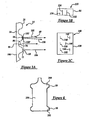
- the apparatus of FIGS. 1-3A produces the image shown in FIG. 3B ; that is, FIG.
- 3B shows the light pattern or image 120 formed on light sensor 36, which in this embodiment is a linear array sensor:
- -Image 120 generally -comprises three image elements 122-126, where the horizontal position of each image element relates to the distance between container sidewall 14 and inspection apparatus 10, and the vertical extent of each image element relates to the signal strength of each reflection.
- Lens system 34 compresses image 120 in the vertical direction such that image element 122 represents two overlapping image elements from two separate rib peaks (beams 80 and 104). This compression can be beneficial in that it reduces the amount of data being produced; a lower data-rate improves problems associated with a slow frame-rate.
- image element 124 is representative of a single rib valley; however, if the container were axially shifted with respect to light line 50 such that two rib valleys 74 were illuminated, then image element 124 would represent two overlapping image elements.
- Image element 126 represents a reflection (beam 86) from an interior surface 106 of the container sidewall. Because light beam 86 passes through the thickness of the sidewall, its strength is attenuated and thus impinges upon light sensor 36 with a lesser signal strength than that of line images 122 and 124. The diminished signal strength produces a line image having a shorter vertical extent.
- image 120 will only include lines 122 and 124.
- light sensor 36 generates a stream of data representative of image 120 which can be provided to information processor 38 in the form of a sensor output signal.
- the information processor preferably scans the light sensor at a constant predetermined interval, either a spatial or a temporal interval, to obtain and analyze this information for various geometric characteristics of container sidewall 14 and ribs 20, including the sidewall thickness, the radial separation of the ribs, the axial separation of the ribs, and any out-of-round conditions of the sidewall and/or the ribs.
- the thickness of the container sidewall between, for example, rib valley 74 and inner sidewall surface 106 is related to the horizontal distance between image elements 124 and 126.
- the thickness or radial separation of the ribs between rib peak 72 and rib valley 74 is related to the horizontal distance between image elements 122 and 124.
- the relative movement of each of the image elements 122, 124 and 126 is representative of out-of-round conditions of the rib peak 72, rib valley 74, and inner sidewall surface 106, respectively.
- element 122 remains in approximately the same image position during rotation of container about its axis 16
- the circumferential surface of the rib peak is round, where if there is a certain degree of movement in the position of element 122, then the rib peak is out-of-round by a certain degree.
- other analysis could be performed with the data provided by light sensor 36. If a container is found to have an unacceptable commercial variation, then that container is flagged as a reject and is removed from the manufacturing process at a downstream station.
- an inspection apparatus is provided as before, only cylindrical lens 60 is removed and light sensor 36 includes an area array sensor 138 instead of a linear array sensor.
- removal of the cylindrical lens creates image 140, where the light beams are not compressed in the vertical direction.
- parallel beams 80 and 104 strike light sensor 36 at different vertical positions and produce separate, non-overlapping image elements 142, 144, respectively, instead of being compressed on top of one another to form a element 122.
- Element 146 is representative of a reflection off of rib valley 74, and elements 148-152 represent reflections from inner surface 106 of the container sidewall.
- cylindrical lens 60 caused only that light reflected from vertical or near-vertical surfaces to impinge upon the light sensor; in this embodiment the lens system allows more light to strike the light sensor.
- image elements 142-146 have a slight curve to them, as they follow the curvature of the ribs more than that of image 120.
- One attribute of this embodiment is that it produces a more detailed image 140 of the container sidewall surface and ribs.
- an inspection station of this embodiment could analyze the axial separation between adjacent rib peaks by monitoring the vertical distance between elements 142 and 144 as the container rotates.
- this embodiment produces a high volume of data or data-rate which can contribute to a slower frame-rate.
- FIG. 4 illustrates implementation of the invention for measuring the height and/or out-of-roundness of one or more ribs that appear as a shoulder bulge 200 and/or a heel bulge 202 on a container 204.
- FIG. 4 illustrates line-shaped beams 50 incident on the shoulder and/or heel bulge.
- the optics and electronics operate in the manner previously described in detail.
Landscapes
- Physics & Mathematics (AREA)
- General Physics & Mathematics (AREA)
- Chemical & Material Sciences (AREA)
- Computer Vision & Pattern Recognition (AREA)
- Health & Medical Sciences (AREA)
- Life Sciences & Earth Sciences (AREA)
- Engineering & Computer Science (AREA)
- Analytical Chemistry (AREA)
- Biochemistry (AREA)
- General Health & Medical Sciences (AREA)
- Immunology (AREA)
- Pathology (AREA)
- Length Measuring Devices By Optical Means (AREA)
- Investigating Materials By The Use Of Optical Means Adapted For Particular Applications (AREA)
Applications Claiming Priority (2)
| Application Number | Priority Date | Filing Date | Title |
|---|---|---|---|
| US10/889,545 US7060999B2 (en) | 2004-07-09 | 2004-07-09 | Apparatus and method for inspecting ribbed containers |
| PCT/US2005/023438 WO2006017041A1 (en) | 2004-07-09 | 2005-06-29 | Apparatus and method for inspecting ribbed containers |
Publications (2)
| Publication Number | Publication Date |
|---|---|
| EP1774298A1 EP1774298A1 (en) | 2007-04-18 |
| EP1774298B1 true EP1774298B1 (en) | 2011-09-21 |
Family
ID=35295340
Family Applications (1)
| Application Number | Title | Priority Date | Filing Date |
|---|---|---|---|
| EP05767726A Expired - Lifetime EP1774298B1 (en) | 2004-07-09 | 2005-06-29 | Apparatus and method for inspecting ribbed containers |
Country Status (12)
| Country | Link |
|---|---|
| US (1) | US7060999B2 (enExample) |
| EP (1) | EP1774298B1 (enExample) |
| JP (1) | JP2008506111A (enExample) |
| CN (1) | CN1985161B (enExample) |
| AR (1) | AR049946A1 (enExample) |
| AT (1) | ATE525639T1 (enExample) |
| AU (1) | AU2005272029B2 (enExample) |
| BR (1) | BRPI0513176A (enExample) |
| MX (1) | MX2007000222A (enExample) |
| MY (1) | MY139150A (enExample) |
| PE (1) | PE20060211A1 (enExample) |
| WO (1) | WO2006017041A1 (enExample) |
Families Citing this family (12)
| Publication number | Priority date | Publication date | Assignee | Title |
|---|---|---|---|---|
| US7148961B1 (en) * | 2004-11-10 | 2006-12-12 | Owens-Brockway Glass Container Inc. | Container sidewall inspection |
| US7480040B2 (en) | 2005-11-22 | 2009-01-20 | Owens-Brockway Glass Container Inc. | Method and apparatus for inspecting container sidewall contour |
| US7582856B2 (en) * | 2006-06-02 | 2009-09-01 | Emhart Glass S.A. | Out of round detector |
| US7385174B2 (en) * | 2006-06-26 | 2008-06-10 | Owens-Brockway Glass Container Inc. | Apparatus and method for measuring sidewall thickness of non-round transparent containers |
| US8548771B2 (en) * | 2008-05-13 | 2013-10-01 | Emhart Glass S.A. | Out-of-round container detection system and method |
| FR2971847B1 (fr) * | 2011-02-18 | 2013-07-19 | Tiama | Procede et dispositif pour detecter des defauts de repartition de matiere dans des recipients transparents |
| US8941825B2 (en) | 2013-03-15 | 2015-01-27 | Owens-Brockway Glass Container Inc. | Container inspection |
| US10012598B2 (en) | 2015-07-17 | 2018-07-03 | Emhart S.A. | Multi-wavelength laser check detection tool |
| JP6769269B2 (ja) * | 2016-12-01 | 2020-10-14 | 富士通株式会社 | 円筒面検査装置および円筒面検査方法 |
| IT201800005143A1 (it) * | 2018-05-08 | 2019-11-08 | Metodo per il controllo di un oggetto in materiale trasparente e relativo sistema di controllo | |
| CN109855547B (zh) * | 2019-01-13 | 2021-04-09 | 宁波鄞科科技咨询有限公司 | 一种汽车玻璃的测量装置 |
| DE102019132655A1 (de) * | 2019-12-02 | 2021-06-02 | Krones Aktiengesellschaft | Verfahren zum Überprüfen einer Wandstärke eines Behälters aus einem zumindest teilweise transparenten Material |
Citations (1)
| Publication number | Priority date | Publication date | Assignee | Title |
|---|---|---|---|---|
| JPS63228049A (ja) * | 1986-10-27 | 1988-09-22 | Fuji Electric Co Ltd | 欠陥検査装置 |
Family Cites Families (44)
| Publication number | Priority date | Publication date | Assignee | Title |
|---|---|---|---|---|
| US3529169A (en) | 1967-12-06 | 1970-09-15 | Fmc Corp | Photoelectric apparatus for detecting shape of bottles |
| JPS4837630B1 (enExample) | 1968-02-02 | 1973-11-12 | ||
| US4021122A (en) | 1973-01-02 | 1977-05-03 | Emhart Zurich S.A. | Glass container inspection machine |
| US3907438A (en) | 1973-06-22 | 1975-09-23 | Gen Electric | Contour measuring system for cylinders |
| FR2378276A1 (fr) | 1977-01-25 | 1978-08-18 | Emballage Ste Gle Pour | Procede et dispositif pour la detection optique de defauts dans des objets transparents, notamment en verre |
| US4368641A (en) | 1981-01-30 | 1983-01-18 | Powers Manufacturing, Inc. | Out-of-round detector |
| IE830387L (en) | 1983-02-23 | 1982-08-16 | Udaras Na Gaeltachta | Inspection apparatus for translucent containers |
| US4672200A (en) | 1985-11-05 | 1987-06-09 | Emhart Industries, Inc. | Optical inspection of transparent layers |
| US4751386A (en) | 1987-03-31 | 1988-06-14 | Emhart Industries, Inc. | Lean detector for determining the offset of an axis of symmetry of a container from its norm |
| CH672955A5 (enExample) | 1987-05-12 | 1990-01-15 | Elpatronic Ag | |
| JPS63304146A (ja) | 1987-06-04 | 1988-12-12 | Kirin Brewery Co Ltd | 壜の胴部検査装置 |
| EP0320139A3 (en) | 1987-12-08 | 1990-08-08 | Emhart Industries, Inc. | Optical measurement of wall thickness of transparent articles |
| JPH0627717B2 (ja) | 1988-04-13 | 1994-04-13 | 株式会社キリンテクノシステム | 壜の胴部検査装置 |
| JPH01299443A (ja) | 1988-05-27 | 1989-12-04 | Kirin Brewery Co Ltd | 光軸変更式壜検査装置 |
| JPH0641924B2 (ja) | 1988-05-27 | 1994-06-01 | 株式会社キリンテクノシステム | 壜胴部の欠陥検出装置 |
| EP0344617B1 (en) | 1988-05-30 | 1995-08-02 | Kabushiki Kaisha Kirin Techno System | Method and apparatus for inspecting sidewalls of bottles |
| FR2642164B1 (fr) | 1989-01-26 | 1991-04-12 | Saint Gobain Cinematique Contr | Controle d'objets a forte cadence |
| EP0456910A1 (en) | 1990-05-14 | 1991-11-21 | Owens-Brockway Glass Container Inc. | Inspection of container finish |
| JPH0465612A (ja) * | 1990-07-05 | 1992-03-02 | Brother Ind Ltd | 光学式表面粗さ測定方法および装置 |
| JPH0736001B2 (ja) | 1990-10-31 | 1995-04-19 | 東洋ガラス株式会社 | びんの欠陥検査方法 |
| US5291271A (en) | 1992-08-19 | 1994-03-01 | Owens-Brockway Glass Container Inc. | Measurement of transparent container wall thickness |
| JPH0785061B2 (ja) | 1993-04-12 | 1995-09-13 | 東洋ガラス株式会社 | 透明ガラス容器の裾底部の異物検査装置 |
| EP0657732A1 (de) | 1993-12-06 | 1995-06-14 | Elpatronic Ag | Verfahren und Vorrichtung zur optischen Prüfung eines durchsichtigen Behälterbereichs, insbesondere des Mündungsbereichs |
| US5489987A (en) | 1994-04-07 | 1996-02-06 | Owens-Brockway Glass Container Inc. | Container sealing surface inspection |
| US5442446A (en) | 1994-08-19 | 1995-08-15 | Owens-Brockaway Glass Container Inc. | Inspection of transparent containers |
| US5747822A (en) | 1994-10-26 | 1998-05-05 | Georgia Tech Research Corporation | Method and apparatus for optically digitizing a three-dimensional object |
| JP2769797B2 (ja) * | 1995-03-15 | 1998-06-25 | 東洋ガラス株式会社 | 透明物体中の微小欠陥検出方法 |
| US6025910A (en) | 1995-09-12 | 2000-02-15 | Coors Brewing Company | Object inspection method utilizing a corrected image to find unknown characteristic |
| JPH09119902A (ja) * | 1995-09-13 | 1997-05-06 | Nippon Glass Kk | 瓶口部・ネジ部ビリ検査装置 |
| JPH09133640A (ja) * | 1995-11-07 | 1997-05-20 | Oji Koei Kk | 欠陥検査方法およびその装置 |
| US5896195A (en) | 1997-05-15 | 1999-04-20 | Owens-Brockway Glass Container Inc. | Container sealing surface area inspection |
| JP3013324B2 (ja) | 1997-10-06 | 2000-02-28 | 株式会社プレシジョン | ガラス容器の口部・ネジ部ビリ検査装置 |
| JPH11248644A (ja) * | 1998-02-26 | 1999-09-17 | Sumitomo Metal Ind Ltd | 容器の欠陥検査方法及びその装置 |
| US6275287B1 (en) | 1998-04-25 | 2001-08-14 | Nihon Yamamura Glass Co., Ltd. | Check detector for glass bottle neck and finish portion |
| AU3991799A (en) | 1998-05-14 | 1999-11-29 | Metacreations Corporation | Structured-light, triangulation-based three-dimensional digitizer |
| US6175107B1 (en) * | 1998-05-27 | 2001-01-16 | Owens-Brockway Glass Container Inc. | Inspection of containers employing a single area array sensor and alternately strobed light sources |
| US6211952B1 (en) * | 1998-10-02 | 2001-04-03 | Agr International, Inc. | Method and apparatus for inspecting glass containers for checks |
| IT1305329B1 (it) | 1998-10-22 | 2001-05-04 | Omso Spa | Dispositivo automatico di rilevazione della qualita' di stampa suflaconi o bottiglie di forma qualunque |
| US6415051B1 (en) | 1999-06-24 | 2002-07-02 | Geometrix, Inc. | Generating 3-D models using a manually operated structured light source |
| US6104482A (en) * | 1999-12-02 | 2000-08-15 | Owens-Brockway Glass Container Inc. | Container finish check detection |
| US6256095B1 (en) | 2000-01-21 | 2001-07-03 | Owens-Brockway Glass Container Inc. | Container sealing surface area inspection |
| US6549292B1 (en) * | 2000-10-17 | 2003-04-15 | Agr International, Inc. | Method and apparatus for inspecting hollow transparent articles |
| US6806459B1 (en) | 2001-08-30 | 2004-10-19 | Owens-Brockway Glass Container Inc. | Measurement of transparent container sidewall thickness |
| JP3917856B2 (ja) * | 2001-12-27 | 2007-05-23 | 大和製罐株式会社 | 容器のネジ部検査装置および検査方法 |
-
2004
- 2004-07-09 US US10/889,545 patent/US7060999B2/en not_active Expired - Lifetime
-
2005
- 2005-06-27 AR ARP050102640A patent/AR049946A1/es active IP Right Grant
- 2005-06-29 BR BRPI0513176-6A patent/BRPI0513176A/pt active Search and Examination
- 2005-06-29 AT AT05767726T patent/ATE525639T1/de not_active IP Right Cessation
- 2005-06-29 EP EP05767726A patent/EP1774298B1/en not_active Expired - Lifetime
- 2005-06-29 CN CN2005800228731A patent/CN1985161B/zh not_active Expired - Fee Related
- 2005-06-29 AU AU2005272029A patent/AU2005272029B2/en not_active Ceased
- 2005-06-29 WO PCT/US2005/023438 patent/WO2006017041A1/en not_active Ceased
- 2005-06-29 MX MX2007000222A patent/MX2007000222A/es active IP Right Grant
- 2005-06-29 JP JP2007520392A patent/JP2008506111A/ja active Pending
- 2005-07-07 MY MYPI20053113A patent/MY139150A/en unknown
- 2005-07-07 PE PE2005000793A patent/PE20060211A1/es not_active Application Discontinuation
Patent Citations (1)
| Publication number | Priority date | Publication date | Assignee | Title |
|---|---|---|---|---|
| JPS63228049A (ja) * | 1986-10-27 | 1988-09-22 | Fuji Electric Co Ltd | 欠陥検査装置 |
Also Published As
| Publication number | Publication date |
|---|---|
| JP2008506111A (ja) | 2008-02-28 |
| ATE525639T1 (de) | 2011-10-15 |
| AU2005272029A1 (en) | 2006-02-16 |
| EP1774298A1 (en) | 2007-04-18 |
| CN1985161A (zh) | 2007-06-20 |
| CN1985161B (zh) | 2010-12-15 |
| PE20060211A1 (es) | 2006-03-20 |
| AR049946A1 (es) | 2006-09-20 |
| BRPI0513176A (pt) | 2008-04-29 |
| WO2006017041A1 (en) | 2006-02-16 |
| MX2007000222A (es) | 2007-03-30 |
| US7060999B2 (en) | 2006-06-13 |
| AU2005272029B2 (en) | 2010-08-19 |
| MY139150A (en) | 2009-08-28 |
| US20060006352A1 (en) | 2006-01-12 |
Similar Documents
| Publication | Publication Date | Title |
|---|---|---|
| US8941825B2 (en) | Container inspection | |
| EP0698776B1 (en) | Optical inspection of container finish dimensional parameters | |
| US6256095B1 (en) | Container sealing surface area inspection | |
| EP1774298B1 (en) | Apparatus and method for inspecting ribbed containers | |
| US20170118457A1 (en) | Non-contact method and system for inspecting a manufactured part at an inspection station having a measurement axis | |
| EP0397833A4 (en) | Article inspections system for analyzing end and adjacent sides | |
| JPH10505680A (ja) | 環状レンズを用いた容器フランジ検査システム | |
| US7010863B1 (en) | Optical inspection apparatus and method for inspecting container lean | |
| CN104870932B (zh) | 用于测量容器壁厚度的设备 | |
| MXPA06008334A (en) | Optical inspection for container lean | |
| JPH11351849A (ja) | 欠陥検査装置及び欠陥検査方法 | |
| JPH02206746A (ja) | 表面検査装置 |
Legal Events
| Date | Code | Title | Description |
|---|---|---|---|
| PUAI | Public reference made under article 153(3) epc to a published international application that has entered the european phase |
Free format text: ORIGINAL CODE: 0009012 |
|
| 17P | Request for examination filed |
Effective date: 20061220 |
|
| AK | Designated contracting states |
Kind code of ref document: A1 Designated state(s): AT BE BG CH CY CZ DE DK EE ES FI FR GB GR HU IE IS IT LI LT LU MC NL PL PT RO SE SI SK TR |
|
| AX | Request for extension of the european patent |
Extension state: AL BA HR LV MK YU |
|
| GRAP | Despatch of communication of intention to grant a patent |
Free format text: ORIGINAL CODE: EPIDOSNIGR1 |
|
| GRAS | Grant fee paid |
Free format text: ORIGINAL CODE: EPIDOSNIGR3 |
|
| GRAA | (expected) grant |
Free format text: ORIGINAL CODE: 0009210 |
|
| AK | Designated contracting states |
Kind code of ref document: B1 Designated state(s): AT BE BG CH CY CZ DE DK EE ES FI FR GB GR HU IE IS IT LI LT LU MC NL PL PT RO SE SI SK TR |
|
| AX | Request for extension of the european patent |
Extension state: AL BA HR LV MK YU |
|
| REG | Reference to a national code |
Ref country code: GB Ref legal event code: FG4D |
|
| REG | Reference to a national code |
Ref country code: CH Ref legal event code: NV Representative=s name: BOVARD AG Ref country code: CH Ref legal event code: EP |
|
| REG | Reference to a national code |
Ref country code: IE Ref legal event code: FG4D |
|
| REG | Reference to a national code |
Ref country code: DE Ref legal event code: R096 Ref document number: 602005030153 Country of ref document: DE Effective date: 20111117 |
|
| REG | Reference to a national code |
Ref country code: SE Ref legal event code: TRGR |
|
| REG | Reference to a national code |
Ref country code: NL Ref legal event code: VDEP Effective date: 20110921 |
|
| PG25 | Lapsed in a contracting state [announced via postgrant information from national office to epo] |
Ref country code: FI Free format text: LAPSE BECAUSE OF FAILURE TO SUBMIT A TRANSLATION OF THE DESCRIPTION OR TO PAY THE FEE WITHIN THE PRESCRIBED TIME-LIMIT Effective date: 20110921 Ref country code: LT Free format text: LAPSE BECAUSE OF FAILURE TO SUBMIT A TRANSLATION OF THE DESCRIPTION OR TO PAY THE FEE WITHIN THE PRESCRIBED TIME-LIMIT Effective date: 20110921 |
|
| LTIE | Lt: invalidation of european patent or patent extension |
Effective date: 20110921 |
|
| PG25 | Lapsed in a contracting state [announced via postgrant information from national office to epo] |
Ref country code: GR Free format text: LAPSE BECAUSE OF FAILURE TO SUBMIT A TRANSLATION OF THE DESCRIPTION OR TO PAY THE FEE WITHIN THE PRESCRIBED TIME-LIMIT Effective date: 20111222 Ref country code: SI Free format text: LAPSE BECAUSE OF FAILURE TO SUBMIT A TRANSLATION OF THE DESCRIPTION OR TO PAY THE FEE WITHIN THE PRESCRIBED TIME-LIMIT Effective date: 20110921 Ref country code: CY Free format text: LAPSE BECAUSE OF FAILURE TO SUBMIT A TRANSLATION OF THE DESCRIPTION OR TO PAY THE FEE WITHIN THE PRESCRIBED TIME-LIMIT Effective date: 20110921 Ref country code: AT Free format text: LAPSE BECAUSE OF FAILURE TO SUBMIT A TRANSLATION OF THE DESCRIPTION OR TO PAY THE FEE WITHIN THE PRESCRIBED TIME-LIMIT Effective date: 20110921 |
|
| REG | Reference to a national code |
Ref country code: AT Ref legal event code: MK05 Ref document number: 525639 Country of ref document: AT Kind code of ref document: T Effective date: 20110921 |
|
| PG25 | Lapsed in a contracting state [announced via postgrant information from national office to epo] |
Ref country code: BE Free format text: LAPSE BECAUSE OF FAILURE TO SUBMIT A TRANSLATION OF THE DESCRIPTION OR TO PAY THE FEE WITHIN THE PRESCRIBED TIME-LIMIT Effective date: 20110921 |
|
| PG25 | Lapsed in a contracting state [announced via postgrant information from national office to epo] |
Ref country code: SK Free format text: LAPSE BECAUSE OF FAILURE TO SUBMIT A TRANSLATION OF THE DESCRIPTION OR TO PAY THE FEE WITHIN THE PRESCRIBED TIME-LIMIT Effective date: 20110921 Ref country code: IS Free format text: LAPSE BECAUSE OF FAILURE TO SUBMIT A TRANSLATION OF THE DESCRIPTION OR TO PAY THE FEE WITHIN THE PRESCRIBED TIME-LIMIT Effective date: 20120121 |
|
| PG25 | Lapsed in a contracting state [announced via postgrant information from national office to epo] |
Ref country code: EE Free format text: LAPSE BECAUSE OF FAILURE TO SUBMIT A TRANSLATION OF THE DESCRIPTION OR TO PAY THE FEE WITHIN THE PRESCRIBED TIME-LIMIT Effective date: 20110921 Ref country code: NL Free format text: LAPSE BECAUSE OF FAILURE TO SUBMIT A TRANSLATION OF THE DESCRIPTION OR TO PAY THE FEE WITHIN THE PRESCRIBED TIME-LIMIT Effective date: 20110921 Ref country code: PL Free format text: LAPSE BECAUSE OF FAILURE TO SUBMIT A TRANSLATION OF THE DESCRIPTION OR TO PAY THE FEE WITHIN THE PRESCRIBED TIME-LIMIT Effective date: 20110921 Ref country code: RO Free format text: LAPSE BECAUSE OF FAILURE TO SUBMIT A TRANSLATION OF THE DESCRIPTION OR TO PAY THE FEE WITHIN THE PRESCRIBED TIME-LIMIT Effective date: 20110921 Ref country code: PT Free format text: LAPSE BECAUSE OF FAILURE TO SUBMIT A TRANSLATION OF THE DESCRIPTION OR TO PAY THE FEE WITHIN THE PRESCRIBED TIME-LIMIT Effective date: 20120123 |
|
| PLBE | No opposition filed within time limit |
Free format text: ORIGINAL CODE: 0009261 |
|
| STAA | Information on the status of an ep patent application or granted ep patent |
Free format text: STATUS: NO OPPOSITION FILED WITHIN TIME LIMIT |
|
| PG25 | Lapsed in a contracting state [announced via postgrant information from national office to epo] |
Ref country code: DK Free format text: LAPSE BECAUSE OF FAILURE TO SUBMIT A TRANSLATION OF THE DESCRIPTION OR TO PAY THE FEE WITHIN THE PRESCRIBED TIME-LIMIT Effective date: 20110921 |
|
| 26N | No opposition filed |
Effective date: 20120622 |
|
| REG | Reference to a national code |
Ref country code: DE Ref legal event code: R097 Ref document number: 602005030153 Country of ref document: DE Effective date: 20120622 |
|
| PG25 | Lapsed in a contracting state [announced via postgrant information from national office to epo] |
Ref country code: MC Free format text: LAPSE BECAUSE OF NON-PAYMENT OF DUE FEES Effective date: 20120630 |
|
| REG | Reference to a national code |
Ref country code: IE Ref legal event code: MM4A |
|
| PG25 | Lapsed in a contracting state [announced via postgrant information from national office to epo] |
Ref country code: IE Free format text: LAPSE BECAUSE OF NON-PAYMENT OF DUE FEES Effective date: 20120629 |
|
| PG25 | Lapsed in a contracting state [announced via postgrant information from national office to epo] |
Ref country code: BG Free format text: LAPSE BECAUSE OF FAILURE TO SUBMIT A TRANSLATION OF THE DESCRIPTION OR TO PAY THE FEE WITHIN THE PRESCRIBED TIME-LIMIT Effective date: 20111221 |
|
| PGFP | Annual fee paid to national office [announced via postgrant information from national office to epo] |
Ref country code: SE Payment date: 20130627 Year of fee payment: 9 Ref country code: CH Payment date: 20130627 Year of fee payment: 9 |
|
| PG25 | Lapsed in a contracting state [announced via postgrant information from national office to epo] |
Ref country code: ES Free format text: LAPSE BECAUSE OF FAILURE TO SUBMIT A TRANSLATION OF THE DESCRIPTION OR TO PAY THE FEE WITHIN THE PRESCRIBED TIME-LIMIT Effective date: 20120101 |
|
| PG25 | Lapsed in a contracting state [announced via postgrant information from national office to epo] |
Ref country code: TR Free format text: LAPSE BECAUSE OF FAILURE TO SUBMIT A TRANSLATION OF THE DESCRIPTION OR TO PAY THE FEE WITHIN THE PRESCRIBED TIME-LIMIT Effective date: 20110921 |
|
| PG25 | Lapsed in a contracting state [announced via postgrant information from national office to epo] |
Ref country code: LU Free format text: LAPSE BECAUSE OF NON-PAYMENT OF DUE FEES Effective date: 20120629 |
|
| PG25 | Lapsed in a contracting state [announced via postgrant information from national office to epo] |
Ref country code: HU Free format text: LAPSE BECAUSE OF FAILURE TO SUBMIT A TRANSLATION OF THE DESCRIPTION OR TO PAY THE FEE WITHIN THE PRESCRIBED TIME-LIMIT Effective date: 20050629 |
|
| PG25 | Lapsed in a contracting state [announced via postgrant information from national office to epo] |
Ref country code: SE Free format text: LAPSE BECAUSE OF NON-PAYMENT OF DUE FEES Effective date: 20140630 |
|
| REG | Reference to a national code |
Ref country code: CH Ref legal event code: PL |
|
| REG | Reference to a national code |
Ref country code: SE Ref legal event code: EUG |
|
| PG25 | Lapsed in a contracting state [announced via postgrant information from national office to epo] |
Ref country code: LI Free format text: LAPSE BECAUSE OF NON-PAYMENT OF DUE FEES Effective date: 20140630 Ref country code: CH Free format text: LAPSE BECAUSE OF NON-PAYMENT OF DUE FEES Effective date: 20140630 |
|
| PGFP | Annual fee paid to national office [announced via postgrant information from national office to epo] |
Ref country code: CZ Payment date: 20150611 Year of fee payment: 11 Ref country code: GB Payment date: 20150629 Year of fee payment: 11 |
|
| PGFP | Annual fee paid to national office [announced via postgrant information from national office to epo] |
Ref country code: IT Payment date: 20150625 Year of fee payment: 11 |
|
| REG | Reference to a national code |
Ref country code: FR Ref legal event code: PLFP Year of fee payment: 12 |
|
| PGFP | Annual fee paid to national office [announced via postgrant information from national office to epo] |
Ref country code: FR Payment date: 20160628 Year of fee payment: 12 |
|
| PG25 | Lapsed in a contracting state [announced via postgrant information from national office to epo] |
Ref country code: CZ Free format text: LAPSE BECAUSE OF NON-PAYMENT OF DUE FEES Effective date: 20160629 |
|
| GBPC | Gb: european patent ceased through non-payment of renewal fee |
Effective date: 20160629 |
|
| PG25 | Lapsed in a contracting state [announced via postgrant information from national office to epo] |
Ref country code: GB Free format text: LAPSE BECAUSE OF NON-PAYMENT OF DUE FEES Effective date: 20160629 |
|
| PG25 | Lapsed in a contracting state [announced via postgrant information from national office to epo] |
Ref country code: IT Free format text: LAPSE BECAUSE OF NON-PAYMENT OF DUE FEES Effective date: 20160629 |
|
| REG | Reference to a national code |
Ref country code: FR Ref legal event code: ST Effective date: 20180228 |
|
| PG25 | Lapsed in a contracting state [announced via postgrant information from national office to epo] |
Ref country code: FR Free format text: LAPSE BECAUSE OF NON-PAYMENT OF DUE FEES Effective date: 20170630 |
|
| PGFP | Annual fee paid to national office [announced via postgrant information from national office to epo] |
Ref country code: DE Payment date: 20190627 Year of fee payment: 15 |
|
| REG | Reference to a national code |
Ref country code: DE Ref legal event code: R119 Ref document number: 602005030153 Country of ref document: DE |
|
| PG25 | Lapsed in a contracting state [announced via postgrant information from national office to epo] |
Ref country code: DE Free format text: LAPSE BECAUSE OF NON-PAYMENT OF DUE FEES Effective date: 20210101 |