EP1774190B1 - Joint homocinetique rotatif - Google Patents
Joint homocinetique rotatif Download PDFInfo
- Publication number
- EP1774190B1 EP1774190B1 EP04763885A EP04763885A EP1774190B1 EP 1774190 B1 EP1774190 B1 EP 1774190B1 EP 04763885 A EP04763885 A EP 04763885A EP 04763885 A EP04763885 A EP 04763885A EP 1774190 B1 EP1774190 B1 EP 1774190B1
- Authority
- EP
- European Patent Office
- Prior art keywords
- antifriction bearing
- rotary
- joint part
- rolling bearing
- ring
- Prior art date
- Legal status (The legal status is an assumption and is not a legal conclusion. Google has not performed a legal analysis and makes no representation as to the accuracy of the status listed.)
- Not-in-force
Links
Images


Classifications
-
- F—MECHANICAL ENGINEERING; LIGHTING; HEATING; WEAPONS; BLASTING
- F16—ENGINEERING ELEMENTS AND UNITS; GENERAL MEASURES FOR PRODUCING AND MAINTAINING EFFECTIVE FUNCTIONING OF MACHINES OR INSTALLATIONS; THERMAL INSULATION IN GENERAL
- F16D—COUPLINGS FOR TRANSMITTING ROTATION; CLUTCHES; BRAKES
- F16D3/00—Yielding couplings, i.e. with means permitting movement between the connected parts during the drive
- F16D3/16—Universal joints in which flexibility is produced by means of pivots or sliding or rolling connecting parts
- F16D3/20—Universal joints in which flexibility is produced by means of pivots or sliding or rolling connecting parts one coupling part entering a sleeve of the other coupling part and connected thereto by sliding or rolling members
- F16D3/202—Universal joints in which flexibility is produced by means of pivots or sliding or rolling connecting parts one coupling part entering a sleeve of the other coupling part and connected thereto by sliding or rolling members one coupling part having radially projecting pins, e.g. tripod joints
- F16D3/205—Universal joints in which flexibility is produced by means of pivots or sliding or rolling connecting parts one coupling part entering a sleeve of the other coupling part and connected thereto by sliding or rolling members one coupling part having radially projecting pins, e.g. tripod joints the pins extending radially outwardly from the coupling part
- F16D3/2055—Universal joints in which flexibility is produced by means of pivots or sliding or rolling connecting parts one coupling part entering a sleeve of the other coupling part and connected thereto by sliding or rolling members one coupling part having radially projecting pins, e.g. tripod joints the pins extending radially outwardly from the coupling part having three pins, i.e. true tripod joints
-
- F—MECHANICAL ENGINEERING; LIGHTING; HEATING; WEAPONS; BLASTING
- F16—ENGINEERING ELEMENTS AND UNITS; GENERAL MEASURES FOR PRODUCING AND MAINTAINING EFFECTIVE FUNCTIONING OF MACHINES OR INSTALLATIONS; THERMAL INSULATION IN GENERAL
- F16D—COUPLINGS FOR TRANSMITTING ROTATION; CLUTCHES; BRAKES
- F16D3/00—Yielding couplings, i.e. with means permitting movement between the connected parts during the drive
- F16D3/16—Universal joints in which flexibility is produced by means of pivots or sliding or rolling connecting parts
- F16D3/20—Universal joints in which flexibility is produced by means of pivots or sliding or rolling connecting parts one coupling part entering a sleeve of the other coupling part and connected thereto by sliding or rolling members
- F16D3/202—Universal joints in which flexibility is produced by means of pivots or sliding or rolling connecting parts one coupling part entering a sleeve of the other coupling part and connected thereto by sliding or rolling members one coupling part having radially projecting pins, e.g. tripod joints
- F16D2003/2026—Universal joints in which flexibility is produced by means of pivots or sliding or rolling connecting parts one coupling part entering a sleeve of the other coupling part and connected thereto by sliding or rolling members one coupling part having radially projecting pins, e.g. tripod joints with trunnion rings, i.e. with tripod joints having rollers supported by a ring on the trunnion
Definitions
- the present invention relates to a constant velocity universal joint according to the preamble of claim 1.
- Constant velocity universal joints are well known and are used in the drive train of vehicles, for example in steerable, driven axles and to compensate for vehicle suspension on the driven wheels.
- Such constant velocity universal joints have the advantage that, while maintaining a uniform, vibration-free torsion transmission, a relatively large angle between the drive part and driven part of the joint can be made possible.
- Constant velocity joints for example, from the published patent applications DE 4210894 A1 and DE 10206733 A1 known.
- a constant velocity universal joint of Tripodebauart is described in which rolling bearings are used with a curvature having outer surface in tracks of the outer joint part.
- the lateral guide surfaces of the webs have a curvature adapted to the rolling bearing, so that each support the rolling bearing at a contact point in the guideway of the outer joint part.
- a disadvantage of this prior art is that the geometric shape of the lateral guide surfaces of the webs due to the curvature manufacturing technology of great effort. Moreover, there is a fairly high Hertzian stress at the contact points under load (stress on contact of two bodies according to the theory of Hertz), so that material fatigue can occur at these points. Furthermore, the rolling bearing in the track has a relatively large amount of play, the so-called backlash, which can lead to the tilting movement of the bearing in the track and thus to restless running of the rotary joint.
- the constant velocity universal joint according to the published patent application DE 102 06 733 A1 also has an adapted to the curvature of the pivot pin of the inner joint part inner ring of the rolling bearing, so that higher tilting forces act through the pivot pin on the rolling bearing.
- each lateral guide surface consists of at least two linear surfaces extending at a specific angle to one another.
- a rolling bearing introduced into a guideway is supported on at least two contact points corresponding to the loading direction on a lateral guide surface of the guideway.
- the force occurring in the loading direction is distributed in this way to two different contact points, so that the Hertzian pressure is reduced at the contact points between the rolling bearing outer surface and the guide surface of the guideway.
- a low backlash can be realized, so that a smooth running of the constant velocity joint is made possible. Due to the geometrically simple linear surfaces of the lateral guide surfaces of the guideways, the outer joint part is relatively easy and inexpensive to manufacture.
- the rolling bearing outer surfaces of the rolling bearing on a curvature in a plane orthogonal to the equatorial plane of the rolling bearing, whose radius is greater than the outer radius in the equatorial plane of the rolling bearing.
- the rolling bearing outer surface of the rolling bearing is spherical, wherein the center of the spherical shape is located on the central axis of the rolling bearing.
- the angle of the mutually extending linear surfaces of the lateral guide surface is adapted to the curvature of the roller bearing outer surface. That way is one Particularly good investment of the guideway to the rolling bearing outer surface possible, whereby the backlash can be kept very low.
- the linear surfaces of the lateral guide surface at the contact points of the rolling contact bearing in each case form a tangential plane to the curvature of the roller bearing outer surface.
- the connecting line from the center of the curvature of the roller bearing outer surface to one of the contact points between rolling bearing outer surface and lateral guide surface with the equatorial plane of the rolling bearing forms an angle which is between 0.5 ° and arcsin [B / (2 ⁇ r)] - Is 0.5 °, preferably between 2 ° and arcsin [B / (2 ⁇ r)] - 2 °, where r is the radius of curvature of the rolling bearing outer surface and B is the width of the rolling bearing in the axial direction of the rolling bearing.
- the contact points between the roller bearing outer surface and lateral guide surface to the side edges of the rolling bearing have a sufficiently large distance, so that there is no breakouts of the material on the rolling bearing outer surface.
- the two contact points on the rolling bearing outer surface are at a sufficient distance to ensure a tilting stability of the rolling bearing in the guideway.
- a rolling bearing introduced into a guideway between the rolling bearing outer surface and the lateral guide surfaces has a clearance of not more than 0.2 mm, preferably not more than 0.1 mm. This makes it possible that with a low tendency to tilt of the bearing in the guideway sufficient lubrication between the guideway and roller bearings is possible, so that the bearings can easily be moved linearly in the guideway.
- the rolling bearing is rounded at the end edges and that the rolling bearing outer surface forms a highlighted, offset from the end edges surface.
- a highlighted surface allows easy production of such rolling bearings with a required for the smooth and trouble-free running of the bearing in the guideway sized surface of the rolling bearing outer surface.
- the invention provides that in each case a lubricant channel is arranged between the lateral guide surfaces of the guide track and the roller bearing outer surfaces. This can be located between the contact points of the rolling bearing outer surfaces with the lateral guide surfaces.
- the pivot pins of the inner joint part each have a coaxial to the axis of the pivot barrel shape.
- the barrel shape preferably has circular curvatures of the outer surface in two mutually orthogonal planes.
- the radius of curvature of the outer surface in the plane of the axis is preferably smaller than the radius of the barrel shape in the equatorial plane orthogonal to the axis of the pivot.
- the rolling bearing has an inner surface, wherein the inner surface and a pivot of the inner joint part are adapted to each other, such that the pivot pin is linearly displaceable in the axial direction of the rolling bearing. Due to the possibility of linear displacement of the pivot in the rolling bearing a lower axial force is exerted on the rolling bearing, whereby the risk of tipping the rolling bearing is reduced. Moreover, the pivot can be particularly easily inserted into the rolling bearing. The manufacture and finishing of such inner surfaces can also be made relatively easy and inexpensive.
- the rolling bearing may consist of a rolling bearing inner ring and a roller bearing outer ring with rolling elements arranged therebetween, wherein the rolling bearing inner ring and the rolling bearing outer ring are fixed against each other in the axial direction of the rolling bearing.
- the rolling elements are fixed in the rolling bearing outer ring.
- the roller bearing inner ring can be pushed in a simple manner in the rolling bearing outer ring during assembly of the rolling bearing, such that the rolling elements between rolling bearing outer ring and roller bearing inner ring are.
- roller bearing inner ring is fixed relative to the rolling bearing outer ring by means of a snap ring and / or a flat ring.
- the roller bearing inner ring relative to the rolling bearing outer ring can be fixed by means of a pressed ring.
- Both alternatives offer a simple way to fix the roller bearing inner ring relative to the roller bearing outer ring. Since the pivot pin is linearly displaceable in the axial direction in one embodiment in the inner ring of the rolling bearing, no large axial forces occur between the rolling bearing inner ring and rolling bearing outer ring, so that correspondingly the explosive, flat and / or pressed-in rings also do not have to absorb any large axial forces. Further, with the aid of this fixation, it is possible to mount the rolling bearing in a simple manner prior to installation in the constant velocity universal joint, so that it can be installed as a unit.
- the outer surface of the outer joint part has a circular cylindrical or a tripodic shape.
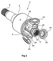
- Fig. 1 an inventive constant velocity joint 1 is shown in an exploded view.
- the constant velocity universal joint consists of a cup-shaped outer joint part 2 and an inner joint part 8.
- the outer joint part 2 has at the distal end a splined shaft 5, which can be used for connection to drive shafts on the axle drive side or for connection to an output shaft.
- the outer joint part 2 has an outer surface 3 and an inner surface 4. Over the circumference of the inner surface 4 at least three extending in the axial direction of the outer joint part 2 guideways 6 are incorporated evenly distributed.
- the outer surface 3 has a circular cylindrical shape.
- the outer surface of the outer joint part 2 may also have a tripodic shape or a tulip shape.
- the circular cylindrical shape has the advantage that it is very easy to manufacture.
- the inner joint part 8 has an annular structure. Inside a wreath 7 is arranged with a splined to which a drive or output shaft can be connected.
- the inner joint part 8 of Fig. 2 has according to the number of guideways 6 of the outer joint part 2 radially projecting at a mutual angle of 120 ° pivot 10.
- the in the Fig. 2 shown preferred embodiment has three guideways 6 and three pivot pins 10, wherein the inner joint part 8 has the shape of a tripod star.
- rolling bearings 12 are pushed.
- the guideways 6 of the outer joint part 2 and the bearings 12 are adapted to each other so that the inner joint part 8 can be inserted with mounted roller bearings 12 in the outer joint part 2, such that the rolling bearings 12 linearly in the axial direction of the constant velocity joint 1 in the guideways 6 of the outer joint part 2 are displaced.
- the rolling bearings 12 are guided by the lateral guide surfaces 16 of the guideways 6, wherein the rolling bearings 12 slide with the rolling bearing outer surfaces 14 along the lateral guide surfaces 16.
- Fig. 2 an inventive constant velocity joint is shown in section.
- the rolling bearings 12 are placed on the pivot pin 10 of the inner joint part 8 and together with the inner joint part 8 in the outer joint part 2 has been inserted.
- the outer joint part 2 the drive part of the constant velocity joint 1, while the inner joint part 8 is a driven part.
- the outer joint part 2 is driven according to the direction of rotation indicated by the arrow.
- the guide surfaces 16 of the guideways 6 abut against the rolling bearing outer surface 14 of the rolling bearings 12.
- each lateral guide surfaces 16 of a guide track 6 and the rolling bearing surface 14 of a rolling bearing 12 each have at least two contact points 20. In this way, a rotational movement of the outer joint part 2 are transmitted to the inner joint part 8, which is also indicated by an arrow of the direction of rotation.
- Fig. 5 a detailed view of a guide track 6 with an inserted roller bearing 12 in the unloaded state shown schematically.
- the lateral guide surface 16 consists in the illustrated example of two at a certain angle ⁇ to each other extending linear surfaces 18a and 18b.
- the rolling bearing outer surface 14 has a curvature with a constant radius, to which the angle ⁇ of the linear surfaces 18a and 18b is adapted such that the linear surfaces 18a and 18b respectively at the contact surfaces 20 form a tangential plane to the curvature of the rolling bearing outer surface.
- the gap between the lateral guide surface 16 and the roller bearing outer surface 14 is widened in the region of the contact edge of the two linear surfaces 18a and 18b, so that a lubricant channel 30 is formed.
- the force to be transmitted is divided equally between the two contact points 20, so that at the contact points 20 there is a lower Hertzian pressure compared to the prior art.
- the tilting stability of the rolling bearing 12 in the guide track 6 is increased because the clearance between the guide track 6 and the rolling bearing 12 is kept particularly small can.
- the lateral guide surfaces 18a and 18b are made linear in the longitudinal direction, they can be easily manufactured and sized particularly well. This is a game or a gap size of max. 0.2 mm, sometimes even max. 0.1 mm, possible.
- the shape of the roller bearing outer surface 14 has two different radii R and r.
- the radius R describes the radius of the rolling bearing 12 in the equatorial plane 24 orthogonal to the axial axis of the rolling bearing. It therefore describes the nominal diameter (maximum outside diameter) of the roller bearing 12.
- the curvature of the roller bearing outer surface 14 rolling bearing 12 In the image plane of Fig. 4 has the radius r. In the in Fig. 4 illustrated embodiment, the radius r is greater than the radius R.
- the rolling bearing outer surface 14 a symmetrical to the equatorial spherical layer of a ball with a center on the central axis 22 of the rolling bearing 12th describes, however, it is advantageous if the radius r of the curvature of the rolling bearing outer surface 14 in the axial direction of the rolling bearing 12 is as large as possible, since in this way the contact points between 20 rolling bearing outer surface 14 and lateral guide surface 16 of the guideways 6 are increased and thus the Hertzian pressure at the contact points 20 is reduced.
- the rolling bearings 12 offset end edges 28, so that the rolling bearing outer surface 14 forms a highlighted offset from the end edges 28 rolling surface.
- the end edges 28 of the rolling bearing 12 are not rounded, so that the roller bearing outer surface 14 extends to the end edges 28.
- the embodiment shown has the advantage that the rolling bearing outer surface 14 can be finished or sized particularly well due to the emphasis.
- the contact points 20 between the roller bearing outer surface 14 and the lateral guide surface 16 should be as far apart as possible to ensure the highest possible tilting stability of the rolling bearing in the guideway, but only so close to the end edges 28 and on the side Edges of the rolling bearing outer surface 14 may be that there may be no material eruptions on the rolling bearing outer surface 14 due to the pressure load at the contact points 20.
- the connecting line 26 from the center of the curvature to one of the contact points 20 between roller bearing outer surface 14 and the lateral guide surface 16 with the equatorial plane 24 of the rolling bearing 12 forms an angle ⁇ , which in the range between 0.5 ° and arcsin [B / (2 ⁇ R)] - 0.5 °.
- the angle ⁇ is between 2 ° and arcsin [B / (2 * r)] -2 °.
- r describes the radius of curvature and B as in FIG Fig. 3 shown, the width of the rolling bearing outer surface in the axial direction of the rolling bearing 12th
- the rolling bearings 12 consist of a roller bearing inner ring 34 and a roller bearing outer ring 36. Rolling elements 38 are arranged between the roller bearing rings.
- the rolling bearing inner ring 34 has an inner surface 32, wherein the inner surface 32 and the pivot pin 10 of the inner joint part 8 are adapted to each other that the pivot pin 10 can slide along the inner surface 32 and thus tilt in the rolling bearing 12 and are linearly displaced relative to the roller bearing 12 can.
- the pivot 10 has in the in Fig. 6 illustrated embodiment, a barrel shape in which the radius of curvature in the axial direction of the pivot pin is smaller than the radius of the pivot in the equatorial plane 33 of the pivot. In other words, the radius of curvature is smaller than the nominal diameter of the pivot 10 determining Radius.
- This so-called radius offset is in Fig. 6 schematically indicated by the parallel to the center line 22 of the pivot 10 guided lines.
- This barrel shape has the advantage that the pivot pin 10 is more easily tilted in the rolling bearing 12 and thus exerts lower forces on the roller bearing 12 during the tilting movement. As a result, the tilting tendency of the roller bearing 12 in the guide track 6 is kept low.
- the rolling bearings 12 can be designed differently.
- the roller bearing inner rings 34 are always fixed relative to the roller bearing outer rings 36 in the axial direction of the rolling bearing.
- the rolling elements 38 are fixed in the rolling bearing outer ring 36.
- the rolling bearing inner ring 34 is pushed into the rolling bearing outer ring 36.
- the roller bearing inner ring 34 can be fixed by means of a flat ring against the rolling bearing outer ring 36. Since no large axial forces occur between roller bearing inner ring 34 and roller bearing outer ring 36, such a flat ring 42 is sufficient for fixing the roller bearing inner ring 34 with respect to the roller bearing outer ring 36.
- a flat ring 42 is sufficient for fixing the roller bearing inner ring 34 with respect to the roller bearing outer ring 36.
- roller bearing inner ring are fixed by means of a pressed-ring 44.
- Fig. 6 illustrated third embodiment of the rolling bearing of the rolling bearing inner ring 34 is fixed with a flat ring 42 and a snap ring 40 relative to the rolling bearing outer ring 36.
Claims (14)
- Joint homocinétique rotatif (1) formé par- une partie externe du joint (2) avec une face externe (3) et une face interne (4), la partie externe du joint (2) comprenant au moins trois chemins de guidage (6) uniformément repartis sur la périphérie de la face interne (4) et s'étendant dans la direction axiale,- une partie interne du joint (8) avec au moins trois tourillons (10) uniformément repartis sur la périphérie et s'étendant dans la direction axiale, et- des roulements à rouleaux situés entre la partie externe du joint (2) et la partie interne du joint (8) et supportés sur les tourillons (10), chaque roulement à rouleaux (12) respectivement comprenant une face externe du roulement à rouleaux (14) adaptée aux chemins de guidage (6) de la partie externe du joint (2) pour le déplacement linéaire de la partie interne du joint (8) dans la direction axiale,- les chemins de guidage (6) respectivement comprenant deux faces de guidage (16) latérales, opposées l'une à l'autre, pour le guidage du roulement à rouleaux (12) dans la direction axiale,caractérisé en ce que
chaque face de guidage (16) latérale est formée par au moins deux faces linéaires (18a, 18b) s'étendant sous un angle (α) défini l'une par rapport à l'autre, de manière à ce que
un roulement à rouleaux (12), inséré dans un chemin de guidage (6), s'appui par au moins deux points de contact (20), en fonction de la direction de charge, sur une face de guidage (16) latérale du chemin de guidage (6), et
la face externe du roulement à rouleaux (14) dudit roulement à rouleaux (12) comprend une courbure dans un plan s'étendant orthogonalement par rapport au plan équatorien (24) du roulement à rouleaux (12), le rayon (r) étant supérieure au rayon externe (R) du roulement à rouleaux (12) dans le plan équatorien (24). - Joint homocinétique rotatif selon la revendication 1, caractérisé en ce que l'angle (α) des faces (18a, 18b) linéaires de la face de guidage (16) latérale, s'étendant l'une vers l'autre, est adapté à la courbure de la face externe du roulement à rouleaux (14).
- Joint homocinétique rotatif selon la revendication 1 ou 2, caractérisé en ce qu'en cas de contact, les faces (18a, 18b) linéaires de la face de guidage (16) latérale respectivement forment un plan tangentiel à la courbure de la face externe du roulement à rouleaux (14) aux points de contact (20) du roulement à rouleaux (12).
- Joint homocinétique rotatif selon l'une des revendications 1 à 3, caractérisé en ce que la ligne de jonction (26) à partir du centre de la courbure jusqu'à un des points de contact (20) forme un angle (β) avec le plan équatorien (24) du roulement à rouleaux (12) entre la face externe du roulement à rouleaux (14) et la face de guidage (16) latérale, ledit angle se situant entre 0,5° et arcsin[B/(2·r)]-2°, de préférence entre 2° et arcsin[B/(2·r)]-2°, où r est le rayon de la courbure et B est la largeur de la face externe du roulement à rouleaux dans la direction axiale du roulement à rouleaux (12).
- Joint homocinétique rotatif selon l'une des revendications 1 à 4, caractérisé en ce qu'un roulement à rouleaux (12) inséré dans un chemin de guidage (6) présente un jeu de 0,2 mm au maximum, de préférence 0,1 mm au maximum, entre la face externe du roulement à rouleaux (14) et les faces de guidage (16) latérales (18a, 18b).
- Joint homocinétique rotatif selon l'une des revendications 1 à 5, caractérisé en ce que le roulement à rouleaux (12) est arrondi aux bords de front (28) et que la face externe du roulement à rouleaux (14) forme une face en relief, étagée des bords de front (28).
- Joint homocinétique rotatif selon l'une des revendications 1 à 6, caractérisé en ce qu'un canal de lubrifiant (30) est respectivement formé entre les faces de guidage (16) latérales des chemins de guidage (6) et les faces externes du roulement à rouleaux (14).
- Joint homocinétique rotatif selon l'une des revendications 1 à 7, caractérisé en ce que les tourillons (10) de la partie interne du joint (8) respectivement ont une forme de tonneau coaxiale à l'axe du tourillon (10), la forme de tonneau préférentiellement comprenant deux courbures de la face externe, en forme de cercle dans deux plans orthogonaux l'un par rapport à l'autre.
- Joint homocinétique rotatif selon l'une des revendications 1 à 8, caractérisé en ce que le roulement à rouleaux (12) comprend une face interne (32), ladite face interne (32) et un tourillon (10) de la partie interne du joint (18) sont adaptés l'un à l'autre de sorte que le tourillon (10) est déplaçable linéairement dans la direction axiale du roulement à rouleaux (12).
- Joint homocinétique rotatif selon l'une des revendications 1 à 9, caractérisé en ce qu'un roulement à rouleaux (12) est formé par un anneau interne du roulement à rouleaux (34) et un anneau externe du roulement à rouleaux (36) avec des corps de rouleaux (38) interposés entre les deux, ledit anneau interne du roulement à rouleaux (34) et ledit anneau externe du roulement à rouleaux (36) sont fixés l'un par rapport à l'autre dans la direction axiale du roulement à rouleaux.
- Joint homocinétique rotatif selon la revendication 10, caractérisé en ce que les corps de rouleaux (38) sont fixés dans ledit anneau externe du roulement à rouleaux (36).
- Joint homocinétique rotatif selon l'une des revendications 10 ou 11, caractérisé en ce que ledit anneau interne du roulement à rouleaux (34) est fixé par rapport audit anneau externe du roulement à rouleaux (36) par un jonc (40) et/ou un anneau plat (42).
- Joint homocinétique rotatif selon la revendication 10 ou 11, caractérisé en ce que ledit anneau interne du roulement à rouleaux (34) est fixé par rapport audit anneau externe du roulement à rouleaux (36) par un anneau (44) pressé là-dedans.
- Joint homocinétique rotatif selon l'une des revendications 1 à 13, caractérisé en ce que la face externe (3) de la partie externe du joint (2) présente une forme circulaire cylindrique ou tripodique.
Applications Claiming Priority (1)
| Application Number | Priority Date | Filing Date | Title |
|---|---|---|---|
| PCT/EP2004/008855 WO2006015610A1 (fr) | 2004-08-06 | 2004-08-06 | Joint homocinetique rotatif |
Publications (2)
| Publication Number | Publication Date |
|---|---|
| EP1774190A1 EP1774190A1 (fr) | 2007-04-18 |
| EP1774190B1 true EP1774190B1 (fr) | 2009-10-21 |
Family
ID=34958467
Family Applications (1)
| Application Number | Title | Priority Date | Filing Date |
|---|---|---|---|
| EP04763885A Not-in-force EP1774190B1 (fr) | 2004-08-06 | 2004-08-06 | Joint homocinetique rotatif |
Country Status (6)
| Country | Link |
|---|---|
| US (1) | US20090305793A1 (fr) |
| EP (1) | EP1774190B1 (fr) |
| JP (1) | JP2008509345A (fr) |
| AT (1) | ATE446456T1 (fr) |
| DE (2) | DE112004002969A5 (fr) |
| WO (1) | WO2006015610A1 (fr) |
Families Citing this family (7)
| Publication number | Priority date | Publication date | Assignee | Title |
|---|---|---|---|---|
| DE102007053999A1 (de) | 2007-11-13 | 2009-05-14 | Volkswagen Ag | Tripodegelenk |
| DE102007059377A1 (de) | 2007-12-10 | 2009-06-18 | Volkswagen Ag | Tripodegelenk |
| KR20120069802A (ko) * | 2010-12-21 | 2012-06-29 | 현대위아 주식회사 | 고절각형 트라이포드 등속조인트 |
| US20140205363A1 (en) * | 2013-01-18 | 2014-07-24 | Dennis Ray Fogle | Coupling Device |
| US10174793B2 (en) * | 2013-10-30 | 2019-01-08 | Steering Solutions Ip Holding Corporation | Tripot constant velocity joint |
| US11098764B2 (en) * | 2017-05-22 | 2021-08-24 | Steering Solutions Ip Holding Corporation | Universal joint or constant velocity joint torque transmission interface |
| DE102018100959A1 (de) * | 2018-01-17 | 2019-07-18 | Schaeffler Technologies AG & Co. KG | Verfahren zur Montage einer Tripodenrolle, Tripodenrolle sowie Gleichlaufgelenk mit der Tripodenrolle |
Family Cites Families (11)
| Publication number | Priority date | Publication date | Assignee | Title |
|---|---|---|---|---|
| JPS62233522A (ja) * | 1986-04-02 | 1987-10-13 | Ntn Toyo Bearing Co Ltd | 等速自在継手 |
| GB8829530D0 (en) * | 1988-12-17 | 1989-02-01 | Spicer Hardy Ltd | Constant velocity ratio universal joints |
| US5167583A (en) * | 1989-11-03 | 1992-12-01 | Gkn Automotive Ag | Tripod joint having an inner part with spherical journals provided with roller members guided in an outer part |
| JPH10246241A (ja) * | 1997-03-05 | 1998-09-14 | Toyoda Mach Works Ltd | トリポード型等速ジョイント |
| FR2785342B1 (fr) * | 1998-11-02 | 2002-05-10 | Ntn Toyo Bearing Co Ltd | Joint homocinetique universel |
| JP2001027257A (ja) * | 1999-07-12 | 2001-01-30 | Derufai Saginoo Nsk Kk | トリポード型等速ジョイント |
| US7022020B2 (en) * | 2000-05-22 | 2006-04-04 | Ntn Corporation | Tripod constant velocity universal joint |
| JP3947342B2 (ja) * | 2000-05-22 | 2007-07-18 | Ntn株式会社 | トリポード型等速自在継手 |
| JP3817415B2 (ja) * | 2000-09-06 | 2006-09-06 | Ntn株式会社 | 等速自在継手 |
| JP4446581B2 (ja) * | 2000-10-03 | 2010-04-07 | デルファイ・テクノロジーズ・インコーポレーテッド | トリポード型等速ジョイント |
| JP3894760B2 (ja) * | 2001-09-26 | 2007-03-22 | Ntn株式会社 | 等速自在継手 |
-
2004
- 2004-08-06 US US11/659,474 patent/US20090305793A1/en not_active Abandoned
- 2004-08-06 WO PCT/EP2004/008855 patent/WO2006015610A1/fr active Application Filing
- 2004-08-06 JP JP2007524182A patent/JP2008509345A/ja active Pending
- 2004-08-06 AT AT04763885T patent/ATE446456T1/de not_active IP Right Cessation
- 2004-08-06 DE DE112004002969T patent/DE112004002969A5/de not_active Withdrawn
- 2004-08-06 EP EP04763885A patent/EP1774190B1/fr not_active Not-in-force
- 2004-08-06 DE DE502004010280T patent/DE502004010280D1/de active Active
Also Published As
| Publication number | Publication date |
|---|---|
| US20090305793A1 (en) | 2009-12-10 |
| DE112004002969A5 (de) | 2007-07-05 |
| WO2006015610A1 (fr) | 2006-02-16 |
| JP2008509345A (ja) | 2008-03-27 |
| ATE446456T1 (de) | 2009-11-15 |
| DE502004010280D1 (de) | 2009-12-03 |
| EP1774190A1 (fr) | 2007-04-18 |
Similar Documents
| Publication | Publication Date | Title |
|---|---|---|
| DE2343540C3 (de) | Gleichgang-Universalgelenk des Tripod-Typs | |
| DE69737661T2 (de) | Gleichlauf-Universalgelenk mit drei Zapfen | |
| DE3134270A1 (de) | Gleichlaufdrehgelenk | |
| WO2002064989A1 (fr) | Dispositif de guidage lineaire pour la transmission de couples | |
| EP2391832B1 (fr) | Joint homocinétique à propriétés de montage améliorées | |
| EP1957811A1 (fr) | Roulement radial, en particulier roulement rainure a une rangee | |
| DE3521174A1 (de) | Gleichlaufgelenk, insbesondere fuer antriebswellen mit hoher drehzahl | |
| DE102010008272A1 (de) | Universalgelenk | |
| EP2126388A2 (fr) | Palier à roulement | |
| DE102006039365B4 (de) | Radial vorgespanntes Wälzlager | |
| EP1774190B1 (fr) | Joint homocinetique rotatif | |
| DE10325116A1 (de) | Gleichlaufdrehgelenk | |
| DE602004009249T2 (de) | Gleichlaufgelenk | |
| EP1286072B1 (fr) | Joint tripode | |
| EP2391833B1 (fr) | Joint homocinétique à propriétés de montage améliorée | |
| EP0552801B1 (fr) | Accouplement à rouleaux | |
| DE112007003668T5 (de) | Tripodegelenk und Rollenkörper für ein Tripodegelenk | |
| DE112005003687B4 (de) | Tripodegelenk mit federnd abgestützten Rollenanordnungen | |
| DE19834142A1 (de) | Homokinetisches Antriebsgelenk in einer Tripodebauart | |
| DE102021212715B4 (de) | Gelenkkreuz für ein Kreuzgelenk, Kreuzgelenk, Lenkwelle eines Kraftfahrzeugs und Lenksystem für ein Kraftfahrzeug | |
| EP2964970B1 (fr) | Joint homocinétique | |
| DE102021206348A1 (de) | Kreuzgelenk für eine Lenkwelle eines Kraftfahrzeugs, Lenkwelle für eine Kraftfahrzeuglenkung, Lenksystem für ein Kraftfahrzeug und Gelenkkreuz für ein Kreuzgelenk | |
| DE10032065C2 (de) | Tripodegelenk mit auf Zapfen und schwenkbaren Segmenten laufenden Rollen | |
| DE102006027300A1 (de) | Tripodegelenk | |
| DE60103787T2 (de) | Stufenlos regelbares Getriebe der toroidalen Bauart |
Legal Events
| Date | Code | Title | Description |
|---|---|---|---|
| PUAI | Public reference made under article 153(3) epc to a published international application that has entered the european phase |
Free format text: ORIGINAL CODE: 0009012 |
|
| 17P | Request for examination filed |
Effective date: 20070131 |
|
| AK | Designated contracting states |
Kind code of ref document: A1 Designated state(s): AT BE BG CH CY CZ DE DK EE ES FI FR GB GR HU IE IT LI LU MC NL PL PT RO SE SI SK TR |
|
| DAX | Request for extension of the european patent (deleted) | ||
| 17Q | First examination report despatched |
Effective date: 20080229 |
|
| GRAP | Despatch of communication of intention to grant a patent |
Free format text: ORIGINAL CODE: EPIDOSNIGR1 |
|
| GRAS | Grant fee paid |
Free format text: ORIGINAL CODE: EPIDOSNIGR3 |
|
| GRAA | (expected) grant |
Free format text: ORIGINAL CODE: 0009210 |
|
| AK | Designated contracting states |
Kind code of ref document: B1 Designated state(s): AT BE BG CH CY CZ DE DK EE ES FI FR GB GR HU IE IT LI LU MC NL PL PT RO SE SI SK TR |
|
| REG | Reference to a national code |
Ref country code: GB Ref legal event code: FG4D Free format text: NOT ENGLISH |
|
| REG | Reference to a national code |
Ref country code: CH Ref legal event code: EP |
|
| REG | Reference to a national code |
Ref country code: IE Ref legal event code: FG4D |
|
| REF | Corresponds to: |
Ref document number: 502004010280 Country of ref document: DE Date of ref document: 20091203 Kind code of ref document: P |
|
| NLV1 | Nl: lapsed or annulled due to failure to fulfill the requirements of art. 29p and 29m of the patents act | ||
| PG25 | Lapsed in a contracting state [announced via postgrant information from national office to epo] |
Ref country code: SE Free format text: LAPSE BECAUSE OF FAILURE TO SUBMIT A TRANSLATION OF THE DESCRIPTION OR TO PAY THE FEE WITHIN THE PRESCRIBED TIME-LIMIT Effective date: 20091021 Ref country code: ES Free format text: LAPSE BECAUSE OF FAILURE TO SUBMIT A TRANSLATION OF THE DESCRIPTION OR TO PAY THE FEE WITHIN THE PRESCRIBED TIME-LIMIT Effective date: 20100201 Ref country code: PT Free format text: LAPSE BECAUSE OF FAILURE TO SUBMIT A TRANSLATION OF THE DESCRIPTION OR TO PAY THE FEE WITHIN THE PRESCRIBED TIME-LIMIT Effective date: 20100222 Ref country code: FI Free format text: LAPSE BECAUSE OF FAILURE TO SUBMIT A TRANSLATION OF THE DESCRIPTION OR TO PAY THE FEE WITHIN THE PRESCRIBED TIME-LIMIT Effective date: 20091021 |
|
| REG | Reference to a national code |
Ref country code: IE Ref legal event code: FD4D |
|
| PG25 | Lapsed in a contracting state [announced via postgrant information from national office to epo] |
Ref country code: SI Free format text: LAPSE BECAUSE OF FAILURE TO SUBMIT A TRANSLATION OF THE DESCRIPTION OR TO PAY THE FEE WITHIN THE PRESCRIBED TIME-LIMIT Effective date: 20091021 Ref country code: PL Free format text: LAPSE BECAUSE OF FAILURE TO SUBMIT A TRANSLATION OF THE DESCRIPTION OR TO PAY THE FEE WITHIN THE PRESCRIBED TIME-LIMIT Effective date: 20091021 |
|
| PG25 | Lapsed in a contracting state [announced via postgrant information from national office to epo] |
Ref country code: RO Free format text: LAPSE BECAUSE OF FAILURE TO SUBMIT A TRANSLATION OF THE DESCRIPTION OR TO PAY THE FEE WITHIN THE PRESCRIBED TIME-LIMIT Effective date: 20091021 Ref country code: DK Free format text: LAPSE BECAUSE OF FAILURE TO SUBMIT A TRANSLATION OF THE DESCRIPTION OR TO PAY THE FEE WITHIN THE PRESCRIBED TIME-LIMIT Effective date: 20091021 Ref country code: IE Free format text: LAPSE BECAUSE OF FAILURE TO SUBMIT A TRANSLATION OF THE DESCRIPTION OR TO PAY THE FEE WITHIN THE PRESCRIBED TIME-LIMIT Effective date: 20091021 Ref country code: EE Free format text: LAPSE BECAUSE OF FAILURE TO SUBMIT A TRANSLATION OF THE DESCRIPTION OR TO PAY THE FEE WITHIN THE PRESCRIBED TIME-LIMIT Effective date: 20091021 Ref country code: BG Free format text: LAPSE BECAUSE OF FAILURE TO SUBMIT A TRANSLATION OF THE DESCRIPTION OR TO PAY THE FEE WITHIN THE PRESCRIBED TIME-LIMIT Effective date: 20100121 |
|
| PLBE | No opposition filed within time limit |
Free format text: ORIGINAL CODE: 0009261 |
|
| STAA | Information on the status of an ep patent application or granted ep patent |
Free format text: STATUS: NO OPPOSITION FILED WITHIN TIME LIMIT |
|
| PG25 | Lapsed in a contracting state [announced via postgrant information from national office to epo] |
Ref country code: SK Free format text: LAPSE BECAUSE OF FAILURE TO SUBMIT A TRANSLATION OF THE DESCRIPTION OR TO PAY THE FEE WITHIN THE PRESCRIBED TIME-LIMIT Effective date: 20091021 Ref country code: CZ Free format text: LAPSE BECAUSE OF FAILURE TO SUBMIT A TRANSLATION OF THE DESCRIPTION OR TO PAY THE FEE WITHIN THE PRESCRIBED TIME-LIMIT Effective date: 20091021 |
|
| 26N | No opposition filed |
Effective date: 20100722 |
|
| PG25 | Lapsed in a contracting state [announced via postgrant information from national office to epo] |
Ref country code: GR Free format text: LAPSE BECAUSE OF FAILURE TO SUBMIT A TRANSLATION OF THE DESCRIPTION OR TO PAY THE FEE WITHIN THE PRESCRIBED TIME-LIMIT Effective date: 20100122 |
|
| BERE | Be: lapsed |
Owner name: IFA TECHNOLOGIES G.M.B.H. Effective date: 20100831 |
|
| PGFP | Annual fee paid to national office [announced via postgrant information from national office to epo] |
Ref country code: DE Payment date: 20101027 Year of fee payment: 7 |
|
| PG25 | Lapsed in a contracting state [announced via postgrant information from national office to epo] |
Ref country code: MC Free format text: LAPSE BECAUSE OF NON-PAYMENT OF DUE FEES Effective date: 20100831 Ref country code: IT Free format text: LAPSE BECAUSE OF FAILURE TO SUBMIT A TRANSLATION OF THE DESCRIPTION OR TO PAY THE FEE WITHIN THE PRESCRIBED TIME-LIMIT Effective date: 20091021 |
|
| REG | Reference to a national code |
Ref country code: CH Ref legal event code: PL |
|
| PG25 | Lapsed in a contracting state [announced via postgrant information from national office to epo] |
Ref country code: CH Free format text: LAPSE BECAUSE OF NON-PAYMENT OF DUE FEES Effective date: 20100831 Ref country code: LI Free format text: LAPSE BECAUSE OF NON-PAYMENT OF DUE FEES Effective date: 20100831 |
|
| PG25 | Lapsed in a contracting state [announced via postgrant information from national office to epo] |
Ref country code: BE Free format text: LAPSE BECAUSE OF NON-PAYMENT OF DUE FEES Effective date: 20100831 |
|
| PG25 | Lapsed in a contracting state [announced via postgrant information from national office to epo] |
Ref country code: AT Free format text: LAPSE BECAUSE OF NON-PAYMENT OF DUE FEES Effective date: 20100806 |
|
| PGFP | Annual fee paid to national office [announced via postgrant information from national office to epo] |
Ref country code: GB Payment date: 20110824 Year of fee payment: 8 Ref country code: FR Payment date: 20110829 Year of fee payment: 8 |
|
| PG25 | Lapsed in a contracting state [announced via postgrant information from national office to epo] |
Ref country code: CY Free format text: LAPSE BECAUSE OF FAILURE TO SUBMIT A TRANSLATION OF THE DESCRIPTION OR TO PAY THE FEE WITHIN THE PRESCRIBED TIME-LIMIT Effective date: 20091021 |
|
| PG25 | Lapsed in a contracting state [announced via postgrant information from national office to epo] |
Ref country code: HU Free format text: LAPSE BECAUSE OF FAILURE TO SUBMIT A TRANSLATION OF THE DESCRIPTION OR TO PAY THE FEE WITHIN THE PRESCRIBED TIME-LIMIT Effective date: 20100422 Ref country code: LU Free format text: LAPSE BECAUSE OF NON-PAYMENT OF DUE FEES Effective date: 20100806 Ref country code: NL Free format text: LAPSE BECAUSE OF FAILURE TO SUBMIT A TRANSLATION OF THE DESCRIPTION OR TO PAY THE FEE WITHIN THE PRESCRIBED TIME-LIMIT Effective date: 20091021 |
|
| PG25 | Lapsed in a contracting state [announced via postgrant information from national office to epo] |
Ref country code: TR Free format text: LAPSE BECAUSE OF FAILURE TO SUBMIT A TRANSLATION OF THE DESCRIPTION OR TO PAY THE FEE WITHIN THE PRESCRIBED TIME-LIMIT Effective date: 20091021 |
|
| GBPC | Gb: european patent ceased through non-payment of renewal fee |
Effective date: 20120806 |
|
| REG | Reference to a national code |
Ref country code: FR Ref legal event code: ST Effective date: 20130430 |
|
| PG25 | Lapsed in a contracting state [announced via postgrant information from national office to epo] |
Ref country code: DE Free format text: LAPSE BECAUSE OF NON-PAYMENT OF DUE FEES Effective date: 20130301 Ref country code: GB Free format text: LAPSE BECAUSE OF NON-PAYMENT OF DUE FEES Effective date: 20120806 |
|
| PG25 | Lapsed in a contracting state [announced via postgrant information from national office to epo] |
Ref country code: FR Free format text: LAPSE BECAUSE OF NON-PAYMENT OF DUE FEES Effective date: 20120831 |
|
| REG | Reference to a national code |
Ref country code: DE Ref legal event code: R119 Ref document number: 502004010280 Country of ref document: DE Effective date: 20130301 |