EP1768580B1 - Wasserstrahlchirurgiepumpe - Google Patents
Wasserstrahlchirurgiepumpe Download PDFInfo
- Publication number
- EP1768580B1 EP1768580B1 EP05761607.0A EP05761607A EP1768580B1 EP 1768580 B1 EP1768580 B1 EP 1768580B1 EP 05761607 A EP05761607 A EP 05761607A EP 1768580 B1 EP1768580 B1 EP 1768580B1
- Authority
- EP
- European Patent Office
- Prior art keywords
- pressure
- pump according
- valve
- fluid outlet
- cylinders
- Prior art date
- Legal status (The legal status is an assumption and is not a legal conclusion. Google has not performed a legal analysis and makes no representation as to the accuracy of the status listed.)
- Expired - Lifetime
Links
Images


Classifications
-
- A—HUMAN NECESSITIES
- A61—MEDICAL OR VETERINARY SCIENCE; HYGIENE
- A61B—DIAGNOSIS; SURGERY; IDENTIFICATION
- A61B17/00—Surgical instruments, devices or methods
- A61B17/32—Surgical cutting instruments
- A61B17/3203—Fluid jet cutting instruments
-
- F—MECHANICAL ENGINEERING; LIGHTING; HEATING; WEAPONS; BLASTING
- F04—POSITIVE - DISPLACEMENT MACHINES FOR LIQUIDS; PUMPS FOR LIQUIDS OR ELASTIC FLUIDS
- F04B—POSITIVE-DISPLACEMENT MACHINES FOR LIQUIDS; PUMPS
- F04B1/00—Multi-cylinder machines or pumps characterised by number or arrangement of cylinders
- F04B1/02—Multi-cylinder machines or pumps characterised by number or arrangement of cylinders having two cylinders
-
- F—MECHANICAL ENGINEERING; LIGHTING; HEATING; WEAPONS; BLASTING
- F04—POSITIVE - DISPLACEMENT MACHINES FOR LIQUIDS; PUMPS FOR LIQUIDS OR ELASTIC FLUIDS
- F04B—POSITIVE-DISPLACEMENT MACHINES FOR LIQUIDS; PUMPS
- F04B49/00—Control, e.g. of pump delivery, or pump pressure of, or safety measures for, machines, pumps, or pumping installations, not otherwise provided for, or of interest apart from, groups F04B1/00 - F04B47/00
- F04B49/02—Stopping, starting, unloading or idling control
- F04B49/03—Stopping, starting, unloading or idling control by means of valves
- F04B49/035—Bypassing
-
- F—MECHANICAL ENGINEERING; LIGHTING; HEATING; WEAPONS; BLASTING
- F04—POSITIVE - DISPLACEMENT MACHINES FOR LIQUIDS; PUMPS FOR LIQUIDS OR ELASTIC FLUIDS
- F04B—POSITIVE-DISPLACEMENT MACHINES FOR LIQUIDS; PUMPS
- F04B53/00—Component parts, details or accessories not provided for in, or of interest apart from, groups F04B1/00 - F04B23/00 or F04B39/00 - F04B47/00
- F04B53/007—Cylinder heads
Definitions
- the invention relates to a water jet surgery pump according to the preamble of claim 1.
- liver surgery the water jet surgery has been used for some time, as this organ has tissue structures of different strength (parenchyma, blood vessels, bile ducts) and thus the applied water jet cuts the tissue to be cut (parenchyma), but the blood vessels and bile ducts undamaged leaves.
- tissue structures of different strength parenchyma, blood vessels, bile ducts
- the applied water jet cuts the tissue to be cut (parenchyma), but the blood vessels and bile ducts undamaged leaves.
- an exact control of the cutting pressure is necessary for this.
- a water jet surgery pump having the features of the preamble of claim 1 is known in which a storage vessel is provided, which is closed by a piston.
- the piston is actuated by a motor so that the cutting fluid is ejected below a predetermined pressure from the engine power.
- the pressure control is complex and inaccurate.
- the invention is based on the object to show a water jet surgery pump which, despite simple and therefore suitable for single use construction allows improved cutting performance.
- This pump comprises an adjustable pressure regulating valve to limit the pressure at a fluid outlet to a presettable maximum value and at least two pistons with piston rods for displacing the pistons in cylinders and coupling to a pump actuator, a cylinder head for closing the cylinders to the pistons, valve means for Connecting a respective pressure chamber in the cylinders with at least one fluid outlet and at least one fluid inlet, wherein the fluid outlet communicating with the fluid inlet via an adjustable pressure control valve is connected such that the pressure in the fluid outlet can be limited to a presettable maximum value, wherein the pressure regulating valve the fluid inlet is arranged to connect with the fluid outlet.
- the pump works with two piston / cylinder devices, an improved, especially uniform flow rate can be achieved.
- the construction is simple, so that a cost-effective manufacturability is guaranteed.
- the (already improved) promotion of the working fluid can be further improved, in particular evened and simultaneously adjusted according to the particular application purposes.
- valve devices and / or the pressure regulating valve preferably comprise an elastic or elastically acted upon valve membrane. This ensures a very cost-effective manufacturability with high reliability.
- valve means may comprise two spring-loaded ball check valves, which are also produced in a simple manner.
- the pressure regulating valve is preferably designed as a force-controlled valve such that the maximum value can be adjusted by a force acting on an actuator of the pressure regulating valve actuating force.
- it is advantageously very easy to couple the medical pump to the pump actuator, with a particularly accurate spatial positioning of the pump to the pump actuator is not necessary.
- the pressure adjustment is not proportional to the distance but just force proportional, it does not depend on the position of the pressure control valve to an actuator (which would require a precise adjustment of the pump to the pump actuator), but it depends only on the position independent force , with which the adjusting member actuates the pressure regulating valve.
- the pressure regulating valve is arranged between the fluid inlet and the fluid outlet such that when the maximum value is exceeded, fluid can be returned from the fluid outlet to the fluid inlet. In this way, independent of the flow rate setting of the pressure is possible.
- the pistons or the piston rods are preferably connected via a bellows, a rolling diaphragm or the like sliding seal with the cylinders tight and impermeable to germs.
- a bellows, a rolling diaphragm or the like sliding seal with the cylinders tight and impermeable to germs.
- valve means and / or the pressure regulating valve are mounted in the cylinder head. This results in a simple, consisting of a few individual pieces construction.
- the cylinders are preferably individually connectable to the cylinder head. This facilitates the manufacturability.
- the outlet has connection means for irreversibly connecting to a pressure hose. This can be ensured that a faulty installation of the pump and also an unauthorized reuse of the pump is avoided.
- the cylinder head preferably has holding devices, in particular retaining projections for latching holding pawls which are attached to the pump actuating device.
- a pressure storage device is provided and formed and connected to the fluid outlet, that pressure fluctuations of the fluid at the fluid outlet are compensated in the manner of a low-pass function. This results in a further homogenization of the cutting beam and thus a Improvement of the intended cutting function of the device.
- the pressure storage devices are preferably arranged in the cylinder head or connected thereto, which facilitates the construction of the overall arrangement.
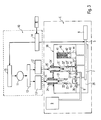
- a pump actuator 10 which includes a motor controller 15 for controlling two motors 11, 11 'connected via gears 12, 12' and coupling means 13, 13 'to piston rods 25, 25'.
- An operator B can by appropriate switching means (foot switch, finger switch) the engine control 15 actuate such that the motors 11, 11 'via the chain described the piston rods 25, 25' and thus pistons 22, 22 'in cylinders 21, 21' of a pump unit 20 alternately move so that pressure chambers 16, 16 'of the pump unit 20 are alternately increased in size and reduced in size.
- seals 23, 23' are provided on the pistons 22, 22 '.
- the piston rods 25, 25 ' via rolling diaphragms 24, 24', which are firmly connected on the one hand with the cylinders 21, 21 'and on the other hand with the piston rods 25, 25', sealed germ-tight. In this way, germs that escape from the ambient air without these rolling diaphragms 24, 24 'on the inner walls of the cylinders 21, 21' and are passed by the seals 23, 23 ', do not mix with the working fluid or get into this.
- Suction valves 26, 26 'and pressure valves 27, 27' are connected to the pressure chambers 16, 16 '.
- a clamping valve 14 is provided, via which (in addition to the motor control 15) an adjustment of the fluid flow by the operator B can take place.
- FIG. 2 embodiment of the invention shown differs from the FIG. 1 in that in accordance with the invention a pressure control valve 35 is provided which can open and close a connection channel between the fluid outlet 7 and the fluid inlet 6 by means of a valve membrane 36.
- the membrane 36 is actuated via a push rod 34 and a spring 33 and a force meter 31 by a servomotor 30.
- the dynamometer 31 delivers a force-proportional output signal to a controller 32, via which an operator B can specify a maximum pressure.
- an actuating current of the servo motor 30 can be measured, which is also proportional to force.
- a pressure accumulator 40 which comprises a cylinder 44 and in this a seal 43 sealed by a piston 42, which is acted upon by a spring 41.
- the space above the piston is connected to the fluid outlet, so that with increasing pressure at the fluid outlet 7, the spring 41 is compressed, while with decreasing pressure, the spring 41, the piston 42 drives. In this way, a homogenization of the applied pressure to the applicator 8 is achieved in the manner of a low-pass function.
- This pressure accumulator 40 is arranged in a cylinder head 29 which closes off the cylinders 21, 21 '.
- the pressure regulating valve 35 can be combined with the pressure accumulator 40.
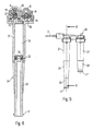
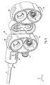
- FIG. 4 a constructive embodiment of the pumping device 20 is shown in an exploded perspective view.
- the pressure and suction valves 26/27 comprise balls 19 which are urged by springs 18 onto valve seats (not visible in the figure), as is known in principle.
- the cylinder head 29 has two sections for coupling the cylinders 21, 21 ', the valves sitting between the cylinders 21, 21' and the cylinder head 29.
- the pistons are formed in this embodiment of the invention by proximal ends of the piston rods 25, 25 'with attached caps 28, which at the same time hold the seals 23, 23' firmly on the piston rods 25, 25 '.
- the pressure hose 5 is irreversibly attached to the cylinder head 29 via a union neck 37, a crimping tube 38 and an inner tube to be inserted into the pressure tube 5, the union neck 37 being held in the cylinder head 29 by means of a snap tongue 45 after plugging together (in a manner known per se), which keeps the union neck 37 in the cylinder head 29 irreversible.
- FIGS. 7 and 8 a section through the pressure regulating valve 35 is shown, from which it can be seen that the membrane 36 can be pressed by the push rod 34 onto a valve seat ( FIG. 7 shows the opened, FIG. 8 the closed state), so that a more or less "short circuit" of the pump unit 20 is generated between the fluid outlet 7 and the fluid inlet 6, depending on the position of the membrane 36. Since the membrane 36 is acted upon by the pressure in the fluid outlet 7, a force-controlled valve is present here.
- FIG. 4 go further constructive details of the cylinder head 29 and the valve means contained therein (suction valve, pressure valve and pressure control valve) forth.
- FIG. 9 Also holding projections 46 shown, via which the pump unit 20 can be coupled to the pump actuator 10 and held firmly on this.
- the pressure control valve 35 is designed as a diaphragm valve, but also the two pressure valves 27, 27 'and suction valves 26, 26' are formed as diaphragm valves instead of the ball valves shown here. This makes the arrangement even more cost effective. Finally, it is also possible to make the arrangement such that not only all valves as diaphragm valves are formed, but all membranes can be integrally connected to each other, so that the number of parts continues to decrease.
Landscapes
- Engineering & Computer Science (AREA)
- Mechanical Engineering (AREA)
- General Engineering & Computer Science (AREA)
- Health & Medical Sciences (AREA)
- Life Sciences & Earth Sciences (AREA)
- Surgery (AREA)
- Heart & Thoracic Surgery (AREA)
- Biomedical Technology (AREA)
- Nuclear Medicine, Radiotherapy & Molecular Imaging (AREA)
- Medical Informatics (AREA)
- Molecular Biology (AREA)
- Animal Behavior & Ethology (AREA)
- General Health & Medical Sciences (AREA)
- Public Health (AREA)
- Veterinary Medicine (AREA)
- Details Of Reciprocating Pumps (AREA)
- Reciprocating Pumps (AREA)
Applications Claiming Priority (2)
| Application Number | Priority Date | Filing Date | Title |
|---|---|---|---|
| DE102004031673A DE102004031673B4 (de) | 2004-06-30 | 2004-06-30 | Medizinische Pumpe |
| PCT/EP2005/006755 WO2006002817A1 (de) | 2004-06-30 | 2005-06-22 | Medizinische pumpe |
Publications (2)
| Publication Number | Publication Date |
|---|---|
| EP1768580A1 EP1768580A1 (de) | 2007-04-04 |
| EP1768580B1 true EP1768580B1 (de) | 2013-09-18 |
Family
ID=34979089
Family Applications (1)
| Application Number | Title | Priority Date | Filing Date |
|---|---|---|---|
| EP05761607.0A Expired - Lifetime EP1768580B1 (de) | 2004-06-30 | 2005-06-22 | Wasserstrahlchirurgiepumpe |
Country Status (7)
Families Citing this family (49)
| Publication number | Priority date | Publication date | Assignee | Title |
|---|---|---|---|---|
| US9232959B2 (en) | 2007-01-02 | 2016-01-12 | Aquabeam, Llc | Multi fluid tissue resection methods and devices |
| US12290277B2 (en) | 2007-01-02 | 2025-05-06 | Aquabeam, Llc | Tissue resection with pressure sensing |
| EP2222957B1 (en) | 2007-12-10 | 2017-01-25 | Bayer Healthcare LLC | Continuous fluid delivery system and method |
| EP2077132A1 (en) | 2008-01-02 | 2009-07-08 | Boehringer Ingelheim Pharma GmbH & Co. KG | Dispensing device, storage device and method for dispensing a formulation |
| EP3622910B1 (en) | 2008-03-06 | 2024-07-10 | AquaBeam LLC | Tissue ablation and cautery with optical energy carried in fluid stream |
| US9848904B2 (en) | 2009-03-06 | 2017-12-26 | Procept Biorobotics Corporation | Tissue resection and treatment with shedding pulses |
| US10011906B2 (en) | 2009-03-31 | 2018-07-03 | Beohringer Ingelheim International Gmbh | Method for coating a surface of a component |
| US9265910B2 (en) | 2009-05-18 | 2016-02-23 | Boehringer Ingelheim International Gmbh | Adapter, inhalation device, and nebulizer |
| EP2275160A1 (de) * | 2009-07-13 | 2011-01-19 | Boehringer Ingelheim International Gmbh | Hochdruckkammer |
| JP5658268B2 (ja) | 2009-11-25 | 2015-01-21 | ベーリンガー インゲルハイム インターナショナル ゲゼルシャフト ミット ベシュレンクテル ハフツング | ネブライザ |
| US10016568B2 (en) | 2009-11-25 | 2018-07-10 | Boehringer Ingelheim International Gmbh | Nebulizer |
| MX2012005961A (es) | 2009-11-25 | 2012-06-14 | Boehringer Ingelheim Int | Nebulizador. |
| US8337175B2 (en) * | 2009-12-22 | 2012-12-25 | Smith & Nephew, Inc. | Disposable pumping system and coupler |
| US9943654B2 (en) | 2010-06-24 | 2018-04-17 | Boehringer Ingelheim International Gmbh | Nebulizer |
| CN101862480B (zh) * | 2010-07-19 | 2012-06-13 | 刘晓程 | 心脏辅助用容量放大器 |
| WO2012130757A1 (de) | 2011-04-01 | 2012-10-04 | Boehringer Ingelheim International Gmbh | Medizinisches gerät mit behälter |
| US9827384B2 (en) | 2011-05-23 | 2017-11-28 | Boehringer Ingelheim International Gmbh | Nebulizer |
| EP2819599B1 (en) | 2012-02-29 | 2018-05-23 | Procept Biorobotics Corporation | Automated image-guided tissue resection and treatment |
| WO2013152894A1 (de) | 2012-04-13 | 2013-10-17 | Boehringer Ingelheim International Gmbh | Zerstäuber mit kodiermitteln |
| EP2711545A1 (de) * | 2012-09-19 | 2014-03-26 | Erbe Elektromedizin GmbH | Pumpeinheit für die Wasserstrahlchirurgie |
| JP6119197B2 (ja) * | 2012-11-07 | 2017-04-26 | セイコーエプソン株式会社 | 液体供給装置、液体供給装置の制御方法、医療機器システム |
| JP6107065B2 (ja) * | 2012-11-12 | 2017-04-05 | セイコーエプソン株式会社 | 液体供給装置、供給方法及び医療機器システム |
| JP6403695B2 (ja) | 2013-02-14 | 2018-10-10 | プロセプト バイオロボティクス コーポレイション | アクアアブレーションアクアビーム眼科手術方法および装置 |
| CN103195681B (zh) * | 2013-04-12 | 2015-06-24 | 中国人民解放军军事医学科学院卫生装备研究所 | 一种医用水刀的双凸轮传动机构 |
| ES2836977T3 (es) | 2013-08-09 | 2021-06-28 | Boehringer Ingelheim Int | Nebulizador |
| WO2015018904A1 (en) | 2013-08-09 | 2015-02-12 | Boehringer Ingelheim International Gmbh | Nebulizer |
| EP2913525A1 (en) * | 2014-02-26 | 2015-09-02 | Garniman SA | Hydraulically driven bellows pump |
| US20170234307A1 (en) * | 2014-03-02 | 2017-08-17 | Swissinnov Product Sarl | Volumetric pump with bleed mechanism |
| US10722666B2 (en) | 2014-05-07 | 2020-07-28 | Boehringer Ingelheim International Gmbh | Nebulizer with axially movable and lockable container and indicator |
| DK3928818T3 (da) | 2014-05-07 | 2023-04-17 | Boehringer Ingelheim Int | Forstøver og beholder |
| AU2015257878B2 (en) | 2014-05-07 | 2019-08-08 | Boehringer Ingelheim International Gmbh | Container, nebulizer and use |
| CN104265619A (zh) * | 2014-09-30 | 2015-01-07 | 罗凤玲 | 一种医用高压泵 |
| WO2016101991A1 (en) * | 2014-12-22 | 2016-06-30 | Synergio Ab | An implantable hydraulic displacement actuator, system, manufacturing and methods thereof |
| CA3207200A1 (en) | 2015-01-09 | 2016-07-14 | Bayer Healthcare Llc | Multiple fluid delivery system with multi-use disposable set and features thereof |
| CN106286201B (zh) * | 2015-05-14 | 2018-12-04 | 惠州海卓科赛医疗有限公司 | 一种稳定高压医用泵 |
| US20170074256A1 (en) * | 2015-09-16 | 2017-03-16 | William Banko | Bi-Metallic Solar Water Filtration Pump |
| EP3258111B8 (de) * | 2016-06-14 | 2018-10-31 | Medaxis Ag | Pumpmodul |
| IT201600072149A1 (it) * | 2016-07-11 | 2018-01-11 | Leuco Spa | Pompa per erogare un liquido. |
| CN106137324A (zh) * | 2016-08-30 | 2016-11-23 | 苏州品诺维新医疗科技有限公司 | 一种供液装置、方法及系统 |
| CN106236200A (zh) * | 2016-08-30 | 2016-12-21 | 苏州品诺维新医疗科技有限公司 | 一种手术器械的蓄水装置、手术器械及操作方法 |
| CN106308886B (zh) * | 2016-08-30 | 2019-04-12 | 苏州涵轩信息科技有限公司 | 一种补液装置及方法 |
| WO2018086137A1 (zh) * | 2016-11-14 | 2018-05-17 | 惠州科赛医疗有限公司 | 一种泵体卡紧装置 |
| WO2018086136A1 (zh) * | 2016-11-14 | 2018-05-17 | 惠州科赛医疗有限公司 | 一种稳压泵 |
| GB2576343B (en) * | 2018-08-15 | 2021-03-17 | Dyson Technology Ltd | Pump assembly |
| RU2685353C1 (ru) * | 2018-10-02 | 2019-04-18 | Общество с ограниченной ответственностью "ТОРЕГ" | Насосная установка |
| NL2024158B1 (en) * | 2019-11-05 | 2021-07-20 | Univ Delft Tech | Waterjet cutting system |
| EP4382746A3 (de) | 2020-11-27 | 2024-09-04 | Erbe Elektromedizin GmbH | Pumpeneinheit für medizinische zwecke |
| DE102021112843A1 (de) | 2021-05-18 | 2022-11-24 | Andreas Pein | Steriler Druckstromerzeuger |
| CN116035659B (zh) * | 2022-12-30 | 2025-04-29 | 南京大地水刀股份有限公司 | 一种医用水刀用超高压发生装置 |
Citations (1)
| Publication number | Priority date | Publication date | Assignee | Title |
|---|---|---|---|---|
| US3958898A (en) * | 1972-03-06 | 1976-05-25 | Waters Associates, Incorporated | Pump control systems |
Family Cites Families (42)
| Publication number | Priority date | Publication date | Assignee | Title |
|---|---|---|---|---|
| US2777456A (en) * | 1952-05-14 | 1957-01-15 | Ey Victor | Gas pressure regulators |
| US3692052A (en) * | 1970-03-27 | 1972-09-19 | Hamish A G Cattanach | Pressure controlled variable pump output by-pass system |
| JPS5312503A (en) * | 1976-07-21 | 1978-02-04 | Atsugi Motor Parts Co Ltd | Reciprocating plunger pumps having automatic centering means |
| US4664136A (en) * | 1981-10-01 | 1987-05-12 | South Bend Controls Inc. | Pressure regulating transducer |
| EP0100784B1 (de) * | 1982-08-13 | 1986-11-20 | Vickers Systems GmbH | Druckbegrenzungsventil mit elektrisch einstellbarem Ansprechwert |
| JPS6285000A (ja) * | 1985-10-08 | 1987-04-18 | 株式会社 タムラ製作所 | ウオ−タジエツト加工方法およびその装置 |
| JPS62151496A (ja) * | 1985-12-26 | 1987-07-06 | 住友精化株式会社 | 獣皮革香気組成物の抽出法 |
| US5066282A (en) * | 1987-09-23 | 1991-11-19 | Leocor, Inc. | Positive displacement piston driven blood pump |
| JPH0284068A (ja) * | 1988-09-20 | 1990-03-26 | Toshiba Corp | 高電圧用サイリスタバルブ |
| US5061241A (en) * | 1989-01-19 | 1991-10-29 | Stephens Jr Harry W | Rapid infusion device |
| JPH07109255B2 (ja) * | 1990-11-24 | 1995-11-22 | 株式会社イー、ピー、ルーム | パルス的流体圧制御装置 |
| JPH04288155A (ja) * | 1991-03-18 | 1992-10-13 | Olympus Optical Co Ltd | 医療用送液装置 |
| JPH0626449A (ja) * | 1991-03-20 | 1994-02-01 | Nissan Motor Co Ltd | 能動型脈圧吸収装置 |
| DE4200976C2 (de) | 1992-01-16 | 1995-08-24 | Andreas Pein | Vorrichtung zum Trennen einer biologischen Struktur, insbesondere des menschlichen Gewebes |
| JPH06192A (ja) * | 1992-06-19 | 1994-01-11 | Olympus Optical Co Ltd | ウォータージェット手術装置 |
| DE4222918A1 (de) * | 1992-07-11 | 1994-01-13 | Karl Eickmann | Hochdruck Anordnung(en) |
| US5295967A (en) * | 1992-09-23 | 1994-03-22 | Becton, Dickinson And Company | Syringe pump having continuous pressure monitoring and display |
| EP0693437B1 (en) * | 1994-07-18 | 1998-12-16 | Wilhelm A. Keller | A cartridge with an exchangeable content package |
| JPH08280697A (ja) * | 1995-04-20 | 1996-10-29 | Olympus Optical Co Ltd | 手術用マニピュレータシステム |
| US6216573B1 (en) * | 1995-06-07 | 2001-04-17 | Hydrocision, Inc. | Fluid jet cutting system |
| US5843022A (en) * | 1995-10-25 | 1998-12-01 | Scimied Life Systems, Inc. | Intravascular device utilizing fluid to extract occlusive material |
| JPH10159719A (ja) * | 1996-11-28 | 1998-06-16 | Hitachi Constr Mach Co Ltd | 油圧ポンプの脈動低減装置 |
| WO1998030260A1 (fr) * | 1997-01-10 | 1998-07-16 | Japan Servo Co., Ltd. | Appareil de transport de liquides |
| US6368080B1 (en) * | 1997-08-04 | 2002-04-09 | Anatole J. Sipin | Continuous fluid injection pump |
| GB9910985D0 (en) * | 1999-05-12 | 1999-07-14 | Smiths Industries Plc | Syringe pumps |
| US6220569B1 (en) * | 2000-01-07 | 2001-04-24 | Clippard Instrument Laboratory, Inc. | Electrically controlled proportional valve |
| WO2001097901A2 (en) * | 2000-06-22 | 2001-12-27 | The Research Foundation Of The State University Of New York At Buffalo | Micro-injection pump |
| DE60131653T2 (de) * | 2000-07-20 | 2008-10-30 | ACIST Medical Systems, Inc., Eden Prairie | Spritzenkolbenverriegelungsmechanismus |
| US6610027B1 (en) * | 2000-08-17 | 2003-08-26 | Mohamed Kaled Mohamed El Hatu | Hemodialysis |
| US6652006B1 (en) * | 2000-10-31 | 2003-11-25 | Frank Digiacomo | Fluid transfer device |
| US6382928B1 (en) * | 2000-11-28 | 2002-05-07 | Kun-Lin Chang | Miniature air pump |
| US20020176788A1 (en) * | 2001-04-27 | 2002-11-28 | Moutafis Timothy E. | High pressure pumping cartridges for medical and surgical pumping and infusion applications |
| JP3946510B2 (ja) * | 2001-12-17 | 2007-07-18 | 新キャタピラー三菱株式会社 | 電気リリーフ弁 |
| DE20200885U1 (de) * | 2002-01-22 | 2003-05-28 | B. Braun Melsungen Ag, 34212 Melsungen | Spritzenpumpe mit Kolbenbremse |
| AU2003215164A1 (en) * | 2002-02-13 | 2003-09-04 | Kuchta, John | Controlled cerebrospinal infusion and shunt system |
| JP2004073373A (ja) * | 2002-08-13 | 2004-03-11 | Atom Medical Corp | シリンジポンプ |
| DE20309616U1 (de) * | 2003-06-20 | 2003-11-13 | Pein, Andreas, 23911 Einhaus | Wasserstrahleinrichtung zum Trennen einer biologischen Struktur |
| DE10348832A1 (de) * | 2003-09-30 | 2006-05-18 | Erbe Elektromedizin Gmbh | Fördereinrichtung für sterile Medien |
| ITMO20040028A1 (it) * | 2004-02-06 | 2004-05-06 | Sidam Di Azzolini Graziano E C | Pompa di infusione per siringhe |
| US7290991B2 (en) * | 2004-02-18 | 2007-11-06 | General Motors Corporation | Dual oil supply pump |
| US20050220639A1 (en) * | 2004-04-02 | 2005-10-06 | Japan Servo Co., Ltd. | Extrusion-type liquid delivery apparatus |
| DE102004021035B3 (de) * | 2004-04-07 | 2005-11-17 | Erbe Elektromedizin Gmbh | Gerät für die Wasserstrahlchirurgie |
-
2004
- 2004-06-30 DE DE102004031673A patent/DE102004031673B4/de not_active Expired - Fee Related
-
2005
- 2005-06-22 JP JP2007518508A patent/JP4925213B2/ja not_active Expired - Fee Related
- 2005-06-22 CN CNB2005800222913A patent/CN100534395C/zh not_active Expired - Fee Related
- 2005-06-22 WO PCT/EP2005/006755 patent/WO2006002817A1/de active Application Filing
- 2005-06-22 EP EP05761607.0A patent/EP1768580B1/de not_active Expired - Lifetime
- 2005-06-22 US US11/630,613 patent/US20090060764A1/en not_active Abandoned
- 2005-06-22 AU AU2005259594A patent/AU2005259594B2/en not_active Ceased
Patent Citations (1)
| Publication number | Priority date | Publication date | Assignee | Title |
|---|---|---|---|---|
| US3958898A (en) * | 1972-03-06 | 1976-05-25 | Waters Associates, Incorporated | Pump control systems |
Also Published As
| Publication number | Publication date |
|---|---|
| AU2005259594B2 (en) | 2010-07-15 |
| JP2008504086A (ja) | 2008-02-14 |
| US20090060764A1 (en) | 2009-03-05 |
| CN1980609A (zh) | 2007-06-13 |
| AU2005259594A1 (en) | 2006-01-12 |
| CN100534395C (zh) | 2009-09-02 |
| JP4925213B2 (ja) | 2012-04-25 |
| DE102004031673B4 (de) | 2009-04-16 |
| EP1768580A1 (de) | 2007-04-04 |
| WO2006002817A1 (de) | 2006-01-12 |
| DE102004031673A1 (de) | 2006-01-26 |
| WO2006002817A8 (de) | 2006-04-20 |
Similar Documents
| Publication | Publication Date | Title |
|---|---|---|
| EP1768580B1 (de) | Wasserstrahlchirurgiepumpe | |
| EP1771117B1 (de) | Medizinische pumpe | |
| EP0259668B1 (de) | Kolbenpumpe für ein Medikamentendosiergerät | |
| EP3591273A1 (de) | Magnetventil | |
| EP0386754A1 (de) | Membranpumpe mit freischwingender Metallmembran | |
| EP0175105A1 (de) | Membranpumpe, insbesondere zum Dosieren von Flüssigkeiten | |
| DE102008003454A1 (de) | Hydraulikfluidpumpe mit einem Dichtelement | |
| DE3248622A1 (de) | Hochdruckreinigungsgeraet | |
| EP0226070B1 (de) | Pumpenanordnung zur dosierten Abgabe von mindestens zwei Komponenten | |
| EP1392962B1 (de) | Kraftstoffeinspritzeinrichtung mit druckübersetzungseinrichtung und druckübersetzungseinrichtung | |
| EP1851098B9 (de) | Kombinierter federspeicher- und betriebsbremszylinder mit einer beatmungseinrichtung | |
| EP1664713A1 (de) | Frostsicherer flüssigkeits drucksensor für abgasreduziersysteme ( dieselmotor ) | |
| EP0361183B1 (de) | Schaltventil mit Keramik-Ventilelementen | |
| EP0187222B1 (de) | Ventilsteuereinrichtung für ein zahnärztliches Gerät | |
| DE102005038483B3 (de) | Mikropumpe | |
| WO2006013142A1 (de) | Kolbenpumpe mit kompakter haltevorrichtung für eine rückstellfeder | |
| DE202004020772U1 (de) | Medizinische Pumpe | |
| DE202019102210U1 (de) | Hydraulischer doppeltwirkender Stellantrieb | |
| DE102008024157B4 (de) | Druckmittelzylinder mit Mitteln zur Erzeugung eines Mindestauslösedrucks | |
| DE102005044582A1 (de) | Hydraulische Aktuatoren | |
| WO2001094821A1 (de) | Ventil zum steuern von flüssigkeiten | |
| DE19921951A1 (de) | Piezobetätigte Kolbenpumpe | |
| DE19951603A1 (de) | Aktuatorvorrichtung zur Erzeugung einer Kraft und/oder einer Bewegung | |
| EP2877745B1 (de) | Dosieranlage sowie dosierpumpe hierfür | |
| DE2452094A1 (de) | Doppelsitzventil |
Legal Events
| Date | Code | Title | Description |
|---|---|---|---|
| PUAI | Public reference made under article 153(3) epc to a published international application that has entered the european phase |
Free format text: ORIGINAL CODE: 0009012 |
|
| 17P | Request for examination filed |
Effective date: 20070130 |
|
| AK | Designated contracting states |
Kind code of ref document: A1 Designated state(s): DE FR GB IT |
|
| 17Q | First examination report despatched |
Effective date: 20070514 |
|
| DAX | Request for extension of the european patent (deleted) | ||
| RBV | Designated contracting states (corrected) |
Designated state(s): DE FR GB IT |
|
| REG | Reference to a national code |
Ref country code: DE Ref legal event code: R079 Ref document number: 502005013983 Country of ref document: DE Free format text: PREVIOUS MAIN CLASS: A61B0017320000 Ipc: A61B0017320300 |
|
| GRAP | Despatch of communication of intention to grant a patent |
Free format text: ORIGINAL CODE: EPIDOSNIGR1 |
|
| RIC1 | Information provided on ipc code assigned before grant |
Ipc: F04B 53/16 20060101ALI20130606BHEP Ipc: F04B 49/22 20060101ALI20130606BHEP Ipc: A61B 17/3203 20060101AFI20130606BHEP Ipc: F04B 11/00 20060101ALI20130606BHEP |
|
| INTG | Intention to grant announced |
Effective date: 20130624 |
|
| GRAS | Grant fee paid |
Free format text: ORIGINAL CODE: EPIDOSNIGR3 |
|
| GRAA | (expected) grant |
Free format text: ORIGINAL CODE: 0009210 |
|
| AK | Designated contracting states |
Kind code of ref document: B1 Designated state(s): DE FR GB IT |
|
| REG | Reference to a national code |
Ref country code: GB Ref legal event code: FG4D Free format text: NOT ENGLISH |
|
| REG | Reference to a national code |
Ref country code: DE Ref legal event code: R096 Ref document number: 502005013983 Country of ref document: DE Effective date: 20131107 |
|
| REG | Reference to a national code |
Ref country code: DE Ref legal event code: R097 Ref document number: 502005013983 Country of ref document: DE |
|
| PLBE | No opposition filed within time limit |
Free format text: ORIGINAL CODE: 0009261 |
|
| STAA | Information on the status of an ep patent application or granted ep patent |
Free format text: STATUS: NO OPPOSITION FILED WITHIN TIME LIMIT |
|
| PGFP | Annual fee paid to national office [announced via postgrant information from national office to epo] |
Ref country code: GB Payment date: 20140630 Year of fee payment: 10 |
|
| 26N | No opposition filed |
Effective date: 20140619 |
|
| PGFP | Annual fee paid to national office [announced via postgrant information from national office to epo] |
Ref country code: IT Payment date: 20140626 Year of fee payment: 10 |
|
| REG | Reference to a national code |
Ref country code: DE Ref legal event code: R097 Ref document number: 502005013983 Country of ref document: DE Effective date: 20140619 |
|
| PGFP | Annual fee paid to national office [announced via postgrant information from national office to epo] |
Ref country code: DE Payment date: 20140829 Year of fee payment: 10 |
|
| PGFP | Annual fee paid to national office [announced via postgrant information from national office to epo] |
Ref country code: FR Payment date: 20140630 Year of fee payment: 10 |
|
| REG | Reference to a national code |
Ref country code: DE Ref legal event code: R119 Ref document number: 502005013983 Country of ref document: DE |
|
| PG25 | Lapsed in a contracting state [announced via postgrant information from national office to epo] |
Ref country code: IT Free format text: LAPSE BECAUSE OF NON-PAYMENT OF DUE FEES Effective date: 20150622 |
|
| GBPC | Gb: european patent ceased through non-payment of renewal fee |
Effective date: 20150622 |
|
| REG | Reference to a national code |
Ref country code: FR Ref legal event code: ST Effective date: 20160229 |
|
| PG25 | Lapsed in a contracting state [announced via postgrant information from national office to epo] |
Ref country code: GB Free format text: LAPSE BECAUSE OF NON-PAYMENT OF DUE FEES Effective date: 20150622 Ref country code: DE Free format text: LAPSE BECAUSE OF NON-PAYMENT OF DUE FEES Effective date: 20160101 |
|
| PG25 | Lapsed in a contracting state [announced via postgrant information from national office to epo] |
Ref country code: FR Free format text: LAPSE BECAUSE OF NON-PAYMENT OF DUE FEES Effective date: 20150630 |