EP1764644B1 - Compensateurs de retardation orientés de maniere optimale - Google Patents
Compensateurs de retardation orientés de maniere optimale Download PDFInfo
- Publication number
- EP1764644B1 EP1764644B1 EP06254535.5A EP06254535A EP1764644B1 EP 1764644 B1 EP1764644 B1 EP 1764644B1 EP 06254535 A EP06254535 A EP 06254535A EP 1764644 B1 EP1764644 B1 EP 1764644B1
- Authority
- EP
- European Patent Office
- Prior art keywords
- axis
- liquid crystal
- wgp
- lcos
- panel
- Prior art date
- Legal status (The legal status is an assumption and is not a legal conclusion. Google has not performed a legal analysis and makes no representation as to the accuracy of the status listed.)
- Not-in-force
Links
- 230000010287 polarization Effects 0.000 claims description 76
- 239000004973 liquid crystal related substance Substances 0.000 claims description 37
- 238000000034 method Methods 0.000 claims description 12
- XUIMIQQOPSSXEZ-UHFFFAOYSA-N Silicon Chemical compound [Si] XUIMIQQOPSSXEZ-UHFFFAOYSA-N 0.000 claims description 7
- 229910052710 silicon Inorganic materials 0.000 claims description 7
- 239000010703 silicon Substances 0.000 claims description 7
- 230000001419 dependent effect Effects 0.000 claims description 6
- 239000004988 Nematic liquid crystal Substances 0.000 claims 2
- 230000003287 optical effect Effects 0.000 description 37
- 230000005540 biological transmission Effects 0.000 description 25
- 238000010586 diagram Methods 0.000 description 23
- 239000011521 glass Substances 0.000 description 21
- 239000000758 substrate Substances 0.000 description 16
- 238000005259 measurement Methods 0.000 description 15
- 238000005286 illumination Methods 0.000 description 10
- 239000010410 layer Substances 0.000 description 10
- 239000000463 material Substances 0.000 description 9
- 238000005070 sampling Methods 0.000 description 8
- 238000004088 simulation Methods 0.000 description 8
- 229920000106 Liquid crystal polymer Polymers 0.000 description 7
- 229910052782 aluminium Inorganic materials 0.000 description 6
- XAGFODPZIPBFFR-UHFFFAOYSA-N aluminium Chemical compound [Al] XAGFODPZIPBFFR-UHFFFAOYSA-N 0.000 description 6
- 239000013078 crystal Substances 0.000 description 6
- 238000009826 distribution Methods 0.000 description 6
- 238000005457 optimization Methods 0.000 description 6
- 239000010409 thin film Substances 0.000 description 6
- 230000008901 benefit Effects 0.000 description 5
- 230000008033 biological extinction Effects 0.000 description 5
- 230000000694 effects Effects 0.000 description 5
- 239000004977 Liquid-crystal polymers (LCPs) Substances 0.000 description 4
- 229920002301 cellulose acetate Polymers 0.000 description 4
- 239000006059 cover glass Substances 0.000 description 4
- 239000010408 film Substances 0.000 description 4
- 239000011888 foil Substances 0.000 description 4
- 239000000203 mixture Substances 0.000 description 4
- 229920000642 polymer Polymers 0.000 description 4
- 239000013598 vector Substances 0.000 description 4
- 238000004364 calculation method Methods 0.000 description 3
- 239000011248 coating agent Substances 0.000 description 3
- 238000000576 coating method Methods 0.000 description 3
- 239000005262 ferroelectric liquid crystals (FLCs) Substances 0.000 description 3
- 230000002829 reductive effect Effects 0.000 description 3
- 239000007787 solid Substances 0.000 description 3
- 206010010071 Coma Diseases 0.000 description 2
- 230000004075 alteration Effects 0.000 description 2
- 238000004458 analytical method Methods 0.000 description 2
- 201000009310 astigmatism Diseases 0.000 description 2
- 230000015556 catabolic process Effects 0.000 description 2
- 230000008859 change Effects 0.000 description 2
- 238000006243 chemical reaction Methods 0.000 description 2
- 150000001875 compounds Chemical class 0.000 description 2
- 238000006731 degradation reaction Methods 0.000 description 2
- 230000005684 electric field Effects 0.000 description 2
- 230000001747 exhibiting effect Effects 0.000 description 2
- 230000004907 flux Effects 0.000 description 2
- 230000000670 limiting effect Effects 0.000 description 2
- 229910052751 metal Inorganic materials 0.000 description 2
- 239000002184 metal Substances 0.000 description 2
- 230000036961 partial effect Effects 0.000 description 2
- 230000008685 targeting Effects 0.000 description 2
- 235000010724 Wisteria floribunda Nutrition 0.000 description 1
- 238000010521 absorption reaction Methods 0.000 description 1
- 238000012512 characterization method Methods 0.000 description 1
- 239000011247 coating layer Substances 0.000 description 1
- 230000000295 complement effect Effects 0.000 description 1
- 238000000354 decomposition reaction Methods 0.000 description 1
- 230000003111 delayed effect Effects 0.000 description 1
- 238000013461 design Methods 0.000 description 1
- 238000005516 engineering process Methods 0.000 description 1
- 230000002708 enhancing effect Effects 0.000 description 1
- 238000005530 etching Methods 0.000 description 1
- 238000002474 experimental method Methods 0.000 description 1
- 230000010354 integration Effects 0.000 description 1
- 238000004519 manufacturing process Methods 0.000 description 1
- 239000011159 matrix material Substances 0.000 description 1
- 238000012986 modification Methods 0.000 description 1
- 230000004048 modification Effects 0.000 description 1
- 238000000059 patterning Methods 0.000 description 1
- 229920002120 photoresistant polymer Polymers 0.000 description 1
- 229920006254 polymer film Polymers 0.000 description 1
- 230000004044 response Effects 0.000 description 1
- 230000000717 retained effect Effects 0.000 description 1
- 230000002441 reversible effect Effects 0.000 description 1
Images


Classifications
-
- H—ELECTRICITY
- H04—ELECTRIC COMMUNICATION TECHNIQUE
- H04N—PICTORIAL COMMUNICATION, e.g. TELEVISION
- H04N9/00—Details of colour television systems
- H04N9/12—Picture reproducers
- H04N9/31—Projection devices for colour picture display, e.g. using electronic spatial light modulators [ESLM]
- H04N9/3141—Constructional details thereof
- H04N9/315—Modulator illumination systems
- H04N9/3167—Modulator illumination systems for polarizing the light beam
-
- G—PHYSICS
- G02—OPTICS
- G02B—OPTICAL ELEMENTS, SYSTEMS OR APPARATUS
- G02B5/00—Optical elements other than lenses
- G02B5/30—Polarising elements
- G02B5/3025—Polarisers, i.e. arrangements capable of producing a definite output polarisation state from an unpolarised input state
- G02B5/3058—Polarisers, i.e. arrangements capable of producing a definite output polarisation state from an unpolarised input state comprising electrically conductive elements, e.g. wire grids, conductive particles
-
- G—PHYSICS
- G02—OPTICS
- G02B—OPTICAL ELEMENTS, SYSTEMS OR APPARATUS
- G02B5/00—Optical elements other than lenses
- G02B5/30—Polarising elements
- G02B5/3083—Birefringent or phase retarding elements
-
- G—PHYSICS
- G02—OPTICS
- G02F—OPTICAL DEVICES OR ARRANGEMENTS FOR THE CONTROL OF LIGHT BY MODIFICATION OF THE OPTICAL PROPERTIES OF THE MEDIA OF THE ELEMENTS INVOLVED THEREIN; NON-LINEAR OPTICS; FREQUENCY-CHANGING OF LIGHT; OPTICAL LOGIC ELEMENTS; OPTICAL ANALOGUE/DIGITAL CONVERTERS
- G02F1/00—Devices or arrangements for the control of the intensity, colour, phase, polarisation or direction of light arriving from an independent light source, e.g. switching, gating or modulating; Non-linear optics
- G02F1/01—Devices or arrangements for the control of the intensity, colour, phase, polarisation or direction of light arriving from an independent light source, e.g. switching, gating or modulating; Non-linear optics for the control of the intensity, phase, polarisation or colour
- G02F1/13—Devices or arrangements for the control of the intensity, colour, phase, polarisation or direction of light arriving from an independent light source, e.g. switching, gating or modulating; Non-linear optics for the control of the intensity, phase, polarisation or colour based on liquid crystals, e.g. single liquid crystal display cells
- G02F1/133—Constructional arrangements; Operation of liquid crystal cells; Circuit arrangements
- G02F1/1333—Constructional arrangements; Manufacturing methods
- G02F1/1335—Structural association of cells with optical devices, e.g. polarisers or reflectors
- G02F1/13363—Birefringent elements, e.g. for optical compensation
- G02F1/133632—Birefringent elements, e.g. for optical compensation with refractive index ellipsoid inclined relative to the LC-layer surface
-
- G—PHYSICS
- G02—OPTICS
- G02F—OPTICAL DEVICES OR ARRANGEMENTS FOR THE CONTROL OF LIGHT BY MODIFICATION OF THE OPTICAL PROPERTIES OF THE MEDIA OF THE ELEMENTS INVOLVED THEREIN; NON-LINEAR OPTICS; FREQUENCY-CHANGING OF LIGHT; OPTICAL LOGIC ELEMENTS; OPTICAL ANALOGUE/DIGITAL CONVERTERS
- G02F1/00—Devices or arrangements for the control of the intensity, colour, phase, polarisation or direction of light arriving from an independent light source, e.g. switching, gating or modulating; Non-linear optics
- G02F1/01—Devices or arrangements for the control of the intensity, colour, phase, polarisation or direction of light arriving from an independent light source, e.g. switching, gating or modulating; Non-linear optics for the control of the intensity, phase, polarisation or colour
- G02F1/13—Devices or arrangements for the control of the intensity, colour, phase, polarisation or direction of light arriving from an independent light source, e.g. switching, gating or modulating; Non-linear optics for the control of the intensity, phase, polarisation or colour based on liquid crystals, e.g. single liquid crystal display cells
- G02F1/133—Constructional arrangements; Operation of liquid crystal cells; Circuit arrangements
- G02F1/1333—Constructional arrangements; Manufacturing methods
- G02F1/1335—Structural association of cells with optical devices, e.g. polarisers or reflectors
- G02F1/13363—Birefringent elements, e.g. for optical compensation
- G02F1/133634—Birefringent elements, e.g. for optical compensation the refractive index Nz perpendicular to the element surface being different from in-plane refractive indices Nx and Ny, e.g. biaxial or with normal optical axis
-
- G—PHYSICS
- G02—OPTICS
- G02F—OPTICAL DEVICES OR ARRANGEMENTS FOR THE CONTROL OF LIGHT BY MODIFICATION OF THE OPTICAL PROPERTIES OF THE MEDIA OF THE ELEMENTS INVOLVED THEREIN; NON-LINEAR OPTICS; FREQUENCY-CHANGING OF LIGHT; OPTICAL LOGIC ELEMENTS; OPTICAL ANALOGUE/DIGITAL CONVERTERS
- G02F1/00—Devices or arrangements for the control of the intensity, colour, phase, polarisation or direction of light arriving from an independent light source, e.g. switching, gating or modulating; Non-linear optics
- G02F1/01—Devices or arrangements for the control of the intensity, colour, phase, polarisation or direction of light arriving from an independent light source, e.g. switching, gating or modulating; Non-linear optics for the control of the intensity, phase, polarisation or colour
- G02F1/13—Devices or arrangements for the control of the intensity, colour, phase, polarisation or direction of light arriving from an independent light source, e.g. switching, gating or modulating; Non-linear optics for the control of the intensity, phase, polarisation or colour based on liquid crystals, e.g. single liquid crystal display cells
- G02F1/137—Devices or arrangements for the control of the intensity, colour, phase, polarisation or direction of light arriving from an independent light source, e.g. switching, gating or modulating; Non-linear optics for the control of the intensity, phase, polarisation or colour based on liquid crystals, e.g. single liquid crystal display cells characterised by the electro-optical or magneto-optical effect, e.g. field-induced phase transition, orientation effect, guest-host interaction or dynamic scattering
- G02F1/139—Devices or arrangements for the control of the intensity, colour, phase, polarisation or direction of light arriving from an independent light source, e.g. switching, gating or modulating; Non-linear optics for the control of the intensity, phase, polarisation or colour based on liquid crystals, e.g. single liquid crystal display cells characterised by the electro-optical or magneto-optical effect, e.g. field-induced phase transition, orientation effect, guest-host interaction or dynamic scattering based on orientation effects in which the liquid crystal remains transparent
- G02F1/1393—Devices or arrangements for the control of the intensity, colour, phase, polarisation or direction of light arriving from an independent light source, e.g. switching, gating or modulating; Non-linear optics for the control of the intensity, phase, polarisation or colour based on liquid crystals, e.g. single liquid crystal display cells characterised by the electro-optical or magneto-optical effect, e.g. field-induced phase transition, orientation effect, guest-host interaction or dynamic scattering based on orientation effects in which the liquid crystal remains transparent the birefringence of the liquid crystal being electrically controlled, e.g. ECB-, DAP-, HAN-, PI-LC cells
-
- H—ELECTRICITY
- H04—ELECTRIC COMMUNICATION TECHNIQUE
- H04N—PICTORIAL COMMUNICATION, e.g. TELEVISION
- H04N9/00—Details of colour television systems
- H04N9/12—Picture reproducers
- H04N9/31—Projection devices for colour picture display, e.g. using electronic spatial light modulators [ESLM]
- H04N9/3102—Projection devices for colour picture display, e.g. using electronic spatial light modulators [ESLM] using two-dimensional electronic spatial light modulators
- H04N9/3105—Projection devices for colour picture display, e.g. using electronic spatial light modulators [ESLM] using two-dimensional electronic spatial light modulators for displaying all colours simultaneously, e.g. by using two or more electronic spatial light modulators
-
- G—PHYSICS
- G02—OPTICS
- G02F—OPTICAL DEVICES OR ARRANGEMENTS FOR THE CONTROL OF LIGHT BY MODIFICATION OF THE OPTICAL PROPERTIES OF THE MEDIA OF THE ELEMENTS INVOLVED THEREIN; NON-LINEAR OPTICS; FREQUENCY-CHANGING OF LIGHT; OPTICAL LOGIC ELEMENTS; OPTICAL ANALOGUE/DIGITAL CONVERTERS
- G02F1/00—Devices or arrangements for the control of the intensity, colour, phase, polarisation or direction of light arriving from an independent light source, e.g. switching, gating or modulating; Non-linear optics
- G02F1/01—Devices or arrangements for the control of the intensity, colour, phase, polarisation or direction of light arriving from an independent light source, e.g. switching, gating or modulating; Non-linear optics for the control of the intensity, phase, polarisation or colour
- G02F1/13—Devices or arrangements for the control of the intensity, colour, phase, polarisation or direction of light arriving from an independent light source, e.g. switching, gating or modulating; Non-linear optics for the control of the intensity, phase, polarisation or colour based on liquid crystals, e.g. single liquid crystal display cells
- G02F1/133—Constructional arrangements; Operation of liquid crystal cells; Circuit arrangements
- G02F1/136—Liquid crystal cells structurally associated with a semi-conducting layer or substrate, e.g. cells forming part of an integrated circuit
- G02F1/1362—Active matrix addressed cells
- G02F1/136277—Active matrix addressed cells formed on a semiconductor substrate, e.g. of silicon
-
- G—PHYSICS
- G02—OPTICS
- G02F—OPTICAL DEVICES OR ARRANGEMENTS FOR THE CONTROL OF LIGHT BY MODIFICATION OF THE OPTICAL PROPERTIES OF THE MEDIA OF THE ELEMENTS INVOLVED THEREIN; NON-LINEAR OPTICS; FREQUENCY-CHANGING OF LIGHT; OPTICAL LOGIC ELEMENTS; OPTICAL ANALOGUE/DIGITAL CONVERTERS
- G02F2203/00—Function characteristic
- G02F2203/02—Function characteristic reflective
-
- G—PHYSICS
- G02—OPTICS
- G02F—OPTICAL DEVICES OR ARRANGEMENTS FOR THE CONTROL OF LIGHT BY MODIFICATION OF THE OPTICAL PROPERTIES OF THE MEDIA OF THE ELEMENTS INVOLVED THEREIN; NON-LINEAR OPTICS; FREQUENCY-CHANGING OF LIGHT; OPTICAL LOGIC ELEMENTS; OPTICAL ANALOGUE/DIGITAL CONVERTERS
- G02F2413/00—Indexing scheme related to G02F1/13363, i.e. to birefringent elements, e.g. for optical compensation, characterised by the number, position, orientation or value of the compensation plates
- G02F2413/10—Indexing scheme related to G02F1/13363, i.e. to birefringent elements, e.g. for optical compensation, characterised by the number, position, orientation or value of the compensation plates with refractive index ellipsoid inclined, or tilted, relative to the LC-layer surface O plate
Definitions
- the present application relates generally to polarization compensation for projection displays, and in particular, to optimally clocked trim retarders and LCD-based projection systems including the same.
- LCDs Liquid-crystal displays
- a high power beam of light is passed through a polarizer before being incident on a LCD panel.
- the LCD panel controls the polarization of the incident light pixel-by-pixel and redirects it towards the corresponding polarizer/analyzer, which then redirects light having the proper polarization to a projection lens that projects an image onto a screen.
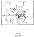
- One particularly successful LCD-based projection system is a WGP-based LCoS microdisplay system, which uses both wire grid polarizers (WGPs) and liquid crystal on silicon (LCoS) panels.
- WGPs wire grid polarizers
- LCD liquid crystal on silicon
- This microdisplay system which has been proven to exhibit both high resolution and high image contrast when compared to other microdisplay technologies such as transmissive liquid crystal (xLCD), digital light processor (DLP), and direct-view LCD, typically uses three or more microdisplay panels (e.g., one for each primary color band) to improve on-screen brightness.
- xLCD transmissive liquid crystal
- DLP digital light processor
- direct-view LCD typically uses three or more microdisplay panels (e.g., one for each primary color band) to improve on-screen brightness.
- the microdisplay system includes a light source 5, which for example is a high-pressure discharge lamp, and a light rod 7.
- the light rod 7 homogenizes the cone of light produced by the light source 5 to ensure a spatially uniform light distribution.
- the light rod 7 is a polarization conversion light pipe (PCLP) for producing linearly polarized light.
- a first lens 8a passes the light from the light pipe 7 to a first folding mirror 9, which directs the light to a first dichroic filter 10.
- the dichroic filter 10 separates out the blue light from the remaining light, and directs the blue light via second 8b and third 8c lenses, and second 17 and third 16 folding mirrors to a first LCoS display panel 20a.
- the remaining light, which is transmitted through the dichroic filter 10, is directed via fourth and fifth lenses 8d and 8e and a fourth folding mirror 11 to a second dichroic filter 12.
- the second dichroic filter 12 separates the remaining light into green and red light, the former of which is directed to a second LCoS display panel 20b and the latter of which passes to a third LCoS display panel 20c.
- Each WGP 15, 14, and 13 is a polarizer/analysisr formed from a plurality of parallel micro-wires that transmits light having a polarization orthogonal to the direction of the parallel micro-wires and reflects light having a polarization parallel to the direction of the wires (e.g., if the polarizers are designed to pass horizontal or P- polarized light, as illustrated in Fig. 1 , the micro-wires will be perpendicular to the plane of Fig. 1 ).
- Each LCoS panel 20a, 20b, and 20c alters the polarization of the linearly polarized incident light pixel-by-pixel and reflects the modulated light back to the corresponding WGP 15, 14, and 13. Since each WGP 15, 14, and 13 is orientated at approximately ⁇ 45° with respect to the principal direction of light propagation, in addition to serving as a polarizer/analyzer, each WGP 15, 13 and 14 also serves as a beamsplitter for separating the incoming light from the outgoing light by steering or deflecting the light reflected from the each LCoS panel along an output optical path orthogonal to the incoming optical path.
- each WGP 15, 14, and 13 reflects S-polarized light (e.g., polarized light rotated by 90° by pixels in an ON state) to the X-cube 19.
- the X-cube 19 aggregates (i.e., converges) the image from each of the three color channels and, via the projection lens 18, projects the final image onto a large screen (not shown).
- each color channel further includes a pre-polarizer (not shown) and/or a clean-up analyzer (not shown), which for example, may include one or more WGPs and/or dichroic sheet polarizers.
- trim retarder compensators 21a, 21b, and 21c are compensating elements used to improve the contrast performance level of the microdisplay system, which is otherwise limited by the residual birefringence of the LCoS panels in the dark (e.g., off) state.
- each trim retarder 21a, 21b, and 21c introduces a phase retardance that cancels the retardance resulting from the inherent birefringence of the corresponding LCoS panel.
- the term 'retardance' or 'retardation' refers to linear retardance magnitude as opposed to circular retardance magnitude, unless stated otherwise.
- Linear retardance is the difference between two orthogonal indices of refraction times the thickness of the optical element.
- Linear retardance causes a phase difference between two orthogonal linear polarizations, where one polarization is aligned parallel to the extra-ordinary axis of the linear retarder and the other polarization is aligned parallel to the ordinary axis of the linear retarder.
- circular retardance causes a relative phase difference between right- and left-handed circular polarized light.
- Linear retardance may be described as either in-plane or out-of-plane retardance.
- In-plane retardance expressed as optical path length difference, refers to the difference between two orthogonal in-plane indices of refraction times the physical thickness of the optical element.
- Out-of-plane retardance refers to the difference of the index of refraction along the thickness direction (z direction) of the optical element and one in-plane index of refraction (or an average of in-plane indices of refraction), times the physical thickness of the optical element.
- Normal incidence rays in a cone bundle see only in-plane retardance, whereas off-axis rays including oblique rays (i.e.
- the P-polarized polarized light that illuminates each microdisplay panel in the dark (off) state is slightly elliptically polarized upon reflection due to the residual birefringence of the LCoS panels 20a-c.
- the elliptically polarized light which contains both a P- and an S- component, is transmitted to the corresponding WGP 15, 14, 13, the S component is reflected to the X-cube thus allowing dark state light leakage onto the large screen and limiting the contrast of the projection system.
- trim retarders 21a-c improves the contrast level by providing in-plane retardance that compensates for the retardance resulting from the residual birefringence in the LCoS panels 20a-c. More specifically, the trim retarders 21 a-c are oriented such that their slow axes are configured at orthogonal azimuthal alignment to the slow axes of the LCoS panels 20a-c (termed "crossed axes"), while their fast axes are configured at orthogonal azimuthal alignment to the fast axes of the LCoS panels 20a-c.
- the terms slow axis (SA) and fast axis (FA), as used herein, refer to the two orthogonal birefringent axes when the linear retardance is measured at normal incidence. Notably, the SA and FA locations change with off-axis illumination as well as reversing the SA/FA roles for a negative out-of-plane retardance component at a large angle of incidence.
- the role of the fast/slow axes switches from the trim retarder 21a-c to the LCoS panel 20a-c for normal incidence light.
- light having a specific polarization is alternately delayed more then less, or vice-versa, in the trim retarder 21a-c and the LCoS panel 20a-c, respectively.
- the net effect is zero relative delay for the incoming polarization, and as a result, an unchanged polarization (i.e., the output light is not elliptically polarized).
- the corresponding WGP 15, 14, 13 and/or optional clean-up polarizer then rejects the output light so that the dark-state panel leakage does not appear on the screen. Since the trim retarders 21a-c do not alter significantly the throughput of the panel on-state, the resulting sequential contrast (full on/full off) is excellent.
- trim retarders 21a-c In addition to providing in-plane retardance, it is common for trim retarders 21a-c to also provide out-of-plane retardance to increase the field of view. More specifically, it is common for trim retarders to include both an A-plate compensation component for compensating the in-plane retardance and a -C-plate compensation component for compensating for out-of plane retardance. Optionally, trim retarders 21a-c also include an O-plate component.
- An A-plate is an optical retarder formed from a uniaxially birefringent material having its extraordinary axis oriented parallel to the plane of the plate.
- a C-plate is an optical retarder formed from a uniaxially birefringent material having its extraordinary axis oriented perpendicular to the plane of the plate (i.e. parallel to the direction of normally incident light).
- a -C-plate exhibits negative birefringence.
- An O-plate is an optical retarder formed from a uniaxial birefringent element having its extraordinary axis (i.e., its optic axis or c-axis) oriented at an oblique angle with respect to the plane of the plate.
- each trim retarder 21a-c ideally provides an A-plate retardance that matches the in-plane retardance of the corresponding LCoS panel 20a-c in the off-state.
- the A-plate retardance of both the LCoS panels 20a-c and the trim retarders 21a-c tends to vary within each component due to manufacturing tolerances in device thickness and material birefringence control, as well as operational drifts (temperature, mechanical stress etc).
- the trim retarder 21a-c tends to vary within each component due to manufacturing tolerances in device thickness and material birefringence control, as well as operational drifts (temperature, mechanical stress etc).
- to ensure adequate compensation it is common to provide a higher A-plate retardance in the trim retarders 21a-c than that exhibited by the LCoS panels 20a-c.
- VAN vertical aligned nematic
- this mismatch in A-plate value requires offsetting of the optic axis of the trim retarder 21a-c, relative to the nominal crossed axes configuration described above.
- the trim retarder is 'clocked-in' by rotating its azimuth orientation away from the crossed-axes configuration.
- K. Tan et al "Design and Characterization of a Compensator for High Contrast LCoS Projection Systems” SID 05, p. 1880, 2005 and/or M. Duelli et al, "High Performance Contrast Enhancing Films for VAN-mode LCoS Panels” SID 05, p. 892, 2005 , on which the preamble of claim 1 is based.
- the slow axis of the panel is typically oriented to be substantially parallel to the bisector of the S- and P-planes (i.e., slow axis at ⁇ 45° and ⁇ 135°, when P-polarization is parallel to 0°/180° and S-polarization is parallel to ⁇ 90°).
- the VAN-LCoS functions approximately as a quarter-waveplate retarder in single pass when the panel is in an on-state.
- the over-clocking angle of a higher value trim retarder is calculated from the following equation: Over ⁇ clocking azimuthal angle ⁇ cos ⁇ 1 ⁇ a LC / ⁇ a TR 2 where ⁇ a (TR) is the trim retarder A-plate retardance and ⁇ a (LC) is the LCoS A-plate retardance.
- Table 1 the calculated over-clocking angles for trim retarders providing 2 to 10 nm A-plate retardance for compensating an LCoS panel exhibiting 2 nm A-plate retardance are shown. Both positive and negative azimuthal offsets are given. In addition, two more azimuthal locations are found in the opposite quadrant (i.e., the listed over-clocking angles ⁇ 180°). Table 1: Approximate over-clocking angles of the trim retarder compensator/VAN-LCoS pair from the nominal crossed-axes configuration.
- the instant invention relates to a method of clocking trim retarders that allows LCoS engines having different panel orientations and/or PBS orientations to exhibit similar system contrasts. More specifically, the instant invention relates to a method of clocking a trim retarder to an azimuthal orientation that is optimal for any one of the four slow-axis quadrant locations of the VAN-LCoS panel and/or for any one of two wiregrid polarizer tilt orientations.
- liquid crystal display based projection system as defined in claim 1.
- a WGP-based LCoS microdisplay system such as the one illustrated in Fig. 1
- these optics form a subsystem including a pre-polarizer 200, a WGP 201, a trim retarder 202, a VAN-mode LCoS panel 203, and a clean-up polarizer 204.
- the pre-polarizer 200 is a polarizer oriented to transmit P-polarized light (e.g., which is shown as a horizontal double-sided arrow).
- the pre-polarizer includes one or more stages of substantially parallel elements of grid-based (reflective) polarizers (e.g., aluminum wiregrid) or regular dichroic sheet (absorptive) polarizers.
- the WGP 201 is a polarizer formed from a plurality of parallel micro-wires disposed on a transparent substrate, as is well known to those skilled in the art.
- the WGP 201 is oriented such that its transmission axis is substantially parallel to the transmission axis of the pre-polarizer 201 and such that the micro-wires are aligned parallel to the y-axis (i.e., so that it also only transmits P-polarized light).
- the wires are located on the rear-side of the WGP substrate (away from the pre-polarizer 201) so that the linear polarized light is less affected by thermal and/or mechanical stress-induced birefringence in the substrate.
- a second benefit of such a WGP arrangement is to reduce astigmatism and coma aberrations of optical elements in the projection path.
- the WGP 201 is not, however, oriented at normal incidence with respect to the central ray of the incident cone bundle. Rather, the WGP 201 is tilted by about 45° degrees with respect to the z-axis. More specifically, the WGP is rotated at +45° about the +y-axis from its initial alignment of being parallel to the XY plane (or simply tilted at +45° w.r.t. z-axis). This adheres to the convention of Euler angle rotation with a right-handed XYZ coordinate system (RH-XYZ). When used in off-normal incidence, as illustrated in Figs.
- the WGP 201 operates in a high polarization-contrast mode if the transmitted linear polarization (e.g., P-polarization) is contained in the plane of incidence (P-plane).
- P-plane plane of incidence
- this high contrast configuration requires the micro-wires to be oriented parallel to the S-plane (orthogonal to the plane of incidence with respect to the central ray).
- the sub-system requires the use of a moderate numerical aperture of each optical element. It is typical to configure the optical elements to function well with f/2.4 system (approximately ⁇ 12° in air incidence).
- the P- and S-plane of polarizations then refer to the linear polarization of the central ray in the cone bundle (hereafter term the principal ray) with respect to each local WGP element.
- the trim retarder 202 is a compensating element, which as discussed above, is used to improve the contrast performance level of the microdisplay system.
- the trim retarder 202 includes an A-plate component and, optionally, a C-plate and/or O-plate component. More specifically, the trim retarder 202 provides a higher A-plate retardance than the in-plane retardance of LCoS 204. As a result, the trim retarder 202 is over-clocked such that its SA 230 is oriented in the neighboring quadrant (i.e., quadrant 3 with respect to RH-XYZ coordinate system) in a non-crossed manner.
- the location of the SA 230 is typically less than 30°, and still more preferably less than 15° from the closest 'S' or 'P' axis.
- Trim retarders are well known in the art. Some examples of materials used to form trim retarders include isotropic polymer that has been stretched either in one or two axes to form a biaxial or uniaxial negative birefringent layer, biaxial organic foil such as cellulose acetate, discotic film, birefringent crystal, inorganic thin film, distorted helix ferroelectric liquid crystal polymer, and/or a liquid crystal mixture crossed linked into a polymer host (LCP).
- LCP polymer host
- the latter has been proven to be very versatile in terms of reliability, uniformity and ease of retardance targeting, and furthermore, to be integrated with inorganic thin-films to provide -C-plate functionality.
- the resulting full function trim retarder has been further proven to provide excellent contrast compensation as well as be environmentally stable.
- the VAN-LCoS panel 203 is a vertically aligned nematic mode liquid crystal on silicon panel, as is well known in the art.
- the panel 203 is shown to include an opaque substrate 203a and a switchable liquid crystal layer 203b. The cover glass and metal reflectors are not shown.
- the LCoS panel 203 is oriented with its slow-axis (SA) 220 located in the fourth quadrant of a RH-XYZ coordinate system, while looking at the beam coming to the observer in the first pass (RH-XYZ).
- SA 220 of a VAN-LCoS panel reference is made to the azimuthal orientation of the SA 220 with a polar angle tilt towards +z axis (positive tilt).
- the fast-axis (FA) 221 of the VAN-LCoS panel is orthogonal to the SA orientation (i.e., ⁇ 90° azimuthal offset to SA).
- the FA 221 is located in quadrant 1, at 45° azimuthal angle from the x-axis.
- the VAN-LCoS 203 is shown being aligned in portrait mode. More specifically, the rectangularly shaped (e.g., 4:3 or 16:9 aspect ratio) display unit is oriented such that the longest dimension is aligned parallel to the WGP wires.
- An advantage of using portrait mode is that the dimension of tilted WGP has to be increased by a factor of ⁇ 1.41 (i.e., 1/cos(45°)) vs. a non-tilted WGP. Therefore the 16/9 aspect ratio of the WGP at normal incidence becomes ⁇ 1.26, rather than ⁇ 2.51 if a landscape mode for VAN-LCoS is chosen.
- a near unity aspect ratio ensures that WGP flexing at high heat and high flux conditions is minimized.
- a VAN-LCoS 203 aligned in landscape mode is also possible.
- the clean-up polarizer 204 is a polarizer oriented to transmit S-polarized light (e.g., which is represented with a vertical double-sided arrow in Fig. 2a and a dot in Fig. 2b ). Both the pre-polarizer 200 and the clean-up polarizer 204 are similarly located and non-tilted with respect to the principal ray propagation direction. According to one embodiment, the clean-up polarizer 204 includes one or more stages of substantially parallel absorptive polarizer elements.
- unpolarized or partial polarized light 240 output from a prior stage illumination is passed through the pre-polarizer 200 to obtain P-polarized light 241.
- the light is transmitted through the WGP 201 and its polarization extinction ratio enhanced.
- the trim retarder 202 preconditions the incoming P-polarization beam and creates an elliptical output. Ideally, the ellipticity in the polarized light incident onto the LCoS panel 204, which is in a dark (off) state, is undone by the residual panel retardance.
- the reflected light after completing a double pass through the VAN-LCoS panel 203 and the trim retarder 202, thus remains P-polarized.
- the exiting light will have accumulated some ellipticity 243.
- the slightly elliptically polarized light 243 is analyzed by the WGP 201. More specifically, the S-polarized component 244 of the elliptically polarized light is deflected by the wire side of the WGP 201 to an orthogonal path 212. This component is termed 'S-leakage' and passes through the clean-up polarizer 204. The leakage is relayed to the screen (not shown) by a projection lens (not shown), and contributes to the degradation of sequential contrast. The remaining P-polarization component 245 transmitted by the WGP 201 is injected back into the illumination system via optical path 213 and is eventually lost.
- Figs. 2c and 2d selected optics from another color-channel of the WGP-based LCoS microdisplay system is shown. These optics form a subsystem including a pre-polarizer 300, a WGP 301, a trim retarder 302, a VAN-mode LCoS panel 303, and a clean-up polarizer 304.
- the pre-polarizer 300 is a polarizer oriented to transmit P-polarized light (e.g., which is shown as a horizontal double-sided arrow).
- the pre-polarizer includes one or more stages of substantially parallel elements of grid-based (reflective) polarizers (e.g., aluminum wiregrid) or regular dichroic sheet (absorptive) polarizers.
- the WGP 301 is a polarizer formed from a plurality of parallel micro-wires disposed on a transparent substrate, as is well known to those skilled in the art.
- the WGP 301 is oriented such that its transmission axis is substantially parallel to the transmission axis of the pre-polarizer 301 and such that the micro-wires are aligned parallel to the y-axis (i.e., so that it also only transmits P-polarized light).
- the wires are located on the rear-side of the WGP substrate (away from the pre-polarizer 301) so that the linear polarized light is less affected by thermal and/or mechanical stress-induced birefringence in the substrate.
- a second benefit of such a WGP arrangement is to reduce astigmatism and coma aberrations of optical elements in the projection path.
- the WGP 301 is not, however, oriented at normal incidence with respect to the central ray of the incident cone bundle. Rather, the WGP 301 is tilted by about 45° degrees with respect to the z-axis. More specifically, the WGP is rotated at -45° about the +y-axis from its initial alignment of being parallel to the XY plane (or simply tilted at -45° w.r.t. z-axis). This adheres to the convention of Euler angle rotation with a right-handed XYZ coordinate system (RH-XYZ). When used in off-normal incidence, as illustrated in Figs.
- the WGP 301 operates in a high polarization-contrast mode if the transmitted linear polarization (e.g., P-polarization) is contained in the plane of incidence (P-plane).
- P-plane plane of incidence
- this high contrast configuration requires the micro-wires to be oriented parallel to the S-plane (orthogonal to the plane of incidence with respect to the central ray).
- the sub-system requires the use of a moderate numerical aperture of each optical element. It is typical to configure the optical elements to function well with f/2.4 system (approximately ⁇ 12° in air incidence).
- the P- and S-plane of polarizations then refer to the linear polarization of the central ray in the cone bundle (hereafter term the principal ray) with respect to each local WGP element.
- the trim retarder 302 is a compensating element, which as discussed above, is used to improve the contrast performance level of the microdisplay system.
- the trim retarder 302 includes an A-plate component and, optionally, a C-plate and/or O-plate component. More specifically, the trim retarder 302 provides a higher A-plate retardance than the in-plane retardance of LCoS 304. As a result, the trim retarder 302 is over-clocked such that its SA 330 is oriented in the neighboring quadrant (i.e., quadrant 3 with respect to RH-XYZ coordinate system) in a non-crossed manner.
- the location of the SA 330 is typically less than 30°, and still more preferably less than 15° from the closest'S' or 'P' axis.
- Trim retarders are well known in the art. Some examples of materials used to form trim retarders include isotropic polymer that has been stretched either in one or two axes to form a biaxial or uniaxial negative birefringent layer, biaxial organic foil such as cellulose acetate, discotic film, birefringent crystal, inorganic thin film, distorted helix ferroelectric liquid crystal polymer, and/or a liquid crystal mixture crossed linked into a polymer host (LCP).
- LCP polymer host
- the latter has been proven to be very versatile in terms of reliability, uniformity and ease of retardance targeting, and furthermore, to be integrated with inorganic thin-films to provide -C-plate functionality.
- the resulting full function trim retarder has been further proven to provide excellent contrast compensation as well as be environmentally stable.
- the VAN-LCoS panel 303 is a vertically aligned nematic mode liquid crystal on silicon panel, as is well known in the art.
- the panel 303 is shown to include an opaque substrate 303a and a switchable liquid crystal layer 303b. The cover glass and metal reflectors are not shown.
- the LCoS panel 303 is oriented with its slow-axis (SA) 320 located in the fourth quadrant of a RH-XYZ coordinate system, while looking at the beam coming to the observer in the first pass (RH-XYZ).
- SA slow-axis
- the fast-axis (FA) 321 of the VAN-LCoS panel is orthogonal to the SA orientation (i.e., ⁇ 90° azimuthal offset to SA).
- the FA 321 is located in quadrant 1, at 45° azimuthal angle from the x-axis.
- the VAN-LCoS 303 is shown being aligned in portrait mode. More specifically, the rectangularly shaped (e.g., 4:3 or 16:9 aspect ratio) display unit is oriented such that the longest dimension is aligned parallel to the WGP wires.
- An advantage of using portrait mode is that the dimension of tilted WGP has to be increased by a factor of ⁇ 1.41 (i.e., 1/cos(45°)) vs. a non-tilted WGP. Therefore the 16/9 aspect ratio of the WGP at normal incidence becomes ⁇ 1.26, rather than ⁇ 2.51 if a landscape mode for VAN-LCoS is chosen.
- a near unity aspect ratio ensures that WGP flexing at high heat and high flux conditions is minimized.
- a VAN-LCoS 303 aligned in landscape mode is also possible.
- the clean-up polarizer 304 is a polarizer oriented to transmit S-polarized light (e.g., which is represented with a vertical double-sided arrow in Fig. 2c and a dot in Fig. 2d ). Both the pre-polarizer 300 and the clean-up polarizer 304 are similarly located and non-tilted with respect to the principal ray propagation direction. According to one embodiment, the clean-up polarizer 304 includes one or more stages of substantially parallel absorptive polarizer elements.
- unpolarized or partial polarized light 340 output from a prior stage illumination is passed through the pre-polarizer 300 to obtain P-polarized light 341.
- the light is transmitted through the WGP 301 and its polarization extinction ratio enhanced.
- the trim retarder 302 preconditions the incoming P-polarization beam and creates an elliptical output.
- the ellipticity in the polarized light incident onto the LCoS panel 304 which is in a dark (off) state, is undone by the residual panel retardance.
- the reflected light after completing a double pass through the VAN-LCoS panel 303 and the trim retarder 302, thus remains P-polarized.
- the exiting light will have accumulated some ellipticity 343.
- the slightly elliptically polarized light 343 is analyzed by the WGP 301. More specifically, the S-polarized component 344 of the elliptically polarized light is deflected by the wire side of the WGP 301 to an orthogonal path 312. This component is termed 'S-leakage' and passes through the clean-up polarizer 304. The leakage is relayed to the screen (not shown) by a projection lens (not shown), and contributes to the degradation of sequential contrast. The remaining P-polarization component 345 transmitted by the WGP 301 is injected back into the illumination system via optical path 313 and is eventually lost.
- the WGP 201 illustrated in Figs. 2a and 2b is tilted at +45° w.r.t. the z-axis, which is the same orientation used in the red and blue color channels of the LCoS projection system illustrated in Fig. 1 (i.e., analogous to 13, 15), whereas the WGP 301 illustrated in Figs. 2c and 2d is tilted at - 45° w.r.t. the z-axis, which is the same orientation used in the green color channel (i.e., analogous to 14). More specifically, the first WGP 201 is the mirror image of the second WGP 301. When the subsystems illustrated in Figs.
- trim retarders 202 and 302 are used in the same LCoS projection system, as for example illustrated in Fig. 1 , the trim retarders 202 and 302 will or will not be identically oriented. Ideally, the same trim retarder is usable for a given LCoS panel for two different orientations of the WGP with indistinguishable overall contrast performance.
- Table 2 Device parameters, assumptions and performance parameters of a simulation of two-stage trim retarder compensator and VAN-LCoS panel birefringence compensation.
- the system baseline contrast is the cone-weighted photopic contrast ratio of the optical system when the panel is replaced by a high quality mirror and the TR is removed from its typical location.
- This baseline quantity measures the off-axis leakage light of the crossed polarizers, including WGP.
- the polarization contrast of the pre-polarizers, WGP and clean-up polarizers is obtained from published data. Assuming that the WGP is only used as a beam-splitting device and both the pre- and clean-up polarizers are made of dichroic sheets, the polarization contrast of the light that is incident on the TR is approximately given by the product of WGP transmitted polarization contrast and dichroic transmitted polarization contrast: 450x1000.
- the overall system contrast is not dependent on the orientation of the slow-axis of the TR.
- numerical results indicate contrast ratio variations of ⁇ 1% for different TR orientations.
- the LCoS panel has its SA oriented at - 45° LH-XYZ system, whereas the nominal SA of the TR is oriented at -98.1° LH-XYZ system.
- the over-clocking angle obtained from the approximate analytic expression is ⁇ 36.7° azimuthal offset from the crossed axes configuration or a further 180° offset of these two locations. None of the four TR orientations in the numerical model produces appreciable difference from the nominal contrast ratio of 6,700:1, assuming a 10,000:1 system baseline contrast.
- the WGP configuration in the experimental set-up was similar to that shown in Fig. 2c , with the WGP tilted at - 45° w.r.t. the z-axis. More specifically, the WGP was tilted at - 45° w.r.t. the z-axis and the SA of the panel was oriented at -45° with reference to LH-XYZ coordinate system (i.e., in the fourth quadrant).
- This configuration which is labelled 540, is clearly illustrated in Fig. 5c .
- the four possible TR SA orientations, which are labelled 546, 547, 548, and 549, were found using the ⁇ over-clocking angles and their ⁇ 180° variants.
- SA orientations 548 and 549 are located in quadrant 1, whereas SA orientations 546 and 547 are located in quadrant 3.
- the actual azimuthal over-clocked angle is dependent on the exact A-plate retardance of the TR and the VAN-LCoS panel, in each color band.
- the experimental contrast ratios were obtained by ratioing the photopically weighted on-stage intensity and off-state intensity values.
- the wavelength range for each color band is given in Table 3.
- the measured system baseline values were 12,000:1, 10,000:1 and 6,000:1, in the red, green and blue wavelength bands, respectively, for a convergent f/2.4 cone of light.
- the optimal system contrast ratios are approximately 4,500, 5,900 and 7,900 to 1 in the blue, green and red wavelength bands, respectively.
- This optimal orientation which corresponds to the TR SA 547 located in quadrant 3, is located between 180° and 225° azimuth angle w.r.t. LH-XYZ coordinate system.
- the gain from comparing the worst TR SA orientation and the optimal TR SA orientation is approximately 35%, 20% and 15%, in the blue, green and red wavelength bands, respectively.
- the azimuthal angles used here are referenced to the RH-XYZ coordinate system.
- the RH-XYZ coordinate system is referenced to the incidence; when viewing the transmitted field, RH-XYZ coordinate system is referenced to the transmitted beam; when viewing the reflected or double-pass transmission field, the RH-XYZ coordinate system is referenced to the returned beam.
- the coordinate sets in the transmitted and incident sides are consistent to each other but the coordinate set in the reflected side has a left-right mirror property versus the incident coordinate set.
- the sign of elliptical eigenpolarization is used consistently in the incident, transmitted and reflected sides.
- the RH-XYZ coordinate system is shown in Fig. 4a .
- the coordinate axes represent the RH-XYZ when specifying the Euler angles (two angles for uniaxial medium and three angles for biaxial medium) w.r.t. viewing the incident beam head-on.
- Polar and azimuthal angles of each uniaxial layer are represented by ( ⁇ c , ⁇ c ).
- the RH-XYZ system is maintained by reversing the direction of the X-axis.
- the RH-XYZ coordinate set for reflection viewing is equivalent to a LH-XYZ coordinate set as referenced to the incident beam (i.e., viewing the back of the incidence).
- the azimuthal angle is defined positive for counter clockwise (CCW) rotation from the positive x-axis.
- CCW counter clockwise
- This axis orientation is used for example to describe the fast/slow axes of a retarder.
- the transmitted viewing plane is aligned to the plane of incidence.
- the viewing plane has a 180° offset from the plane of incidence (for a 360° azimuthal plane range and a 0 to 90° polar angle range).
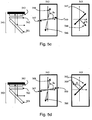
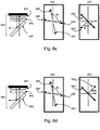
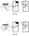
- Figs. 5a-d shows a first configuration 500 including four possible SA orientations (506, 507, 508, and 509) of the TR 502 for a first LCoS panel 503 orientation wherein the LCoS SA 504 is located in quadrant 3 substantially orthogonal to the fast axis 505.
- Fig. 5a shows a first configuration 500 including four possible SA orientations (506, 507, 508, and 509) of the TR 502 for a first LCoS panel 503 orientation wherein the LCoS SA 504 is located in quadrant 3 substantially orthogonal to the fast axis 505.
- FIG. 5b shows a second configuration 520 including four possible SA orientations (526, 527, 528, and 529) of the TR 522 for a second LCoS panel 523 orientation wherein the LCoS SA 524 is located in quadrant 1 substantially orthogonal to the fast axis 525.
- Fig. 5c shows a third configuration 540 including four possible SA orientations (546, 547, 548, and 549) of the TR 542 for a third LCoS panel 543 orientation wherein the LCoS SA 544 is located in quadrant 4 substantially orthogonal to the fast axis 545.
- Fig. 5c shows a third configuration 540 including four possible SA orientations (546, 547, 548, and 549) of the TR 542 for a third LCoS panel 543 orientation wherein the LCoS SA 544 is located in quadrant 4 substantially orthogonal to the fast axis 545.
- 5d shows a fourth configuration 560 including four possible SA orientations (566, 567, 568, and 569) of the TR 562 for a fourth LCoS panel 563 orientation wherein the LCoS SA 564 is located in quadrant 2 substantially XYZ to the fast axis 565.
- These configurations 500, 520, 540 and 560 are referenced to LH-XYZ coordinate system.
- the SA 504, 524, 544, and 564 of the panels are assumed to substantially bisect the system S- and P-polarization directions (for example within ⁇ 10° of bisector).
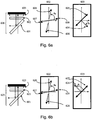
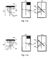
- Figs. 6a-d the four possible LCoS panel SA orientations, and sixteen possible TR SA orientations, when the WGP is oriented at + 45° w.r.t. z-axis, are shown. More specifically, Fig. 6a shows a first configuration 600 including four possible SA orientations (606, 607, 608, and 609) of the TR 602 for the third LCoS panel 603 orientation wherein the LCoS SA 604 is located in quadrant 4 substantially orthogonal to the fast axis 605. Fig.
- FIG. 6b shows a second configuration 620 including four possible SA orientations (626, 627, 628, and 629) of the TR 622 for the fourth LCoS panel 623 orientation wherein the LCoS SA 624 is located in quadrant 2 substantially orthogonal to the fast axis 625.
- Fig. 6c shows a third configuration 640 including four possible SA orientations (646, 647, 648, and 649) of the TR 642 for the first LCoS panel 643 orientation wherein the LCoS SA 644 is located in quadrant 3 substantially orthogonal to the fast axis 645.
- FIG. 6d shows a fourth configuration 660 including four possible SA orientations (666, 667, 668, and 669) of the TR 662 for the second LCoS panel 663 orientation wherein the LCoS SA 664 is located in quadrant 1 substantially orthogonal to the fast axis 665.
- the four possible optical system configurations which are referred to as 600, 620, 640 and 660, are mirror images (about the y-axis) of configurations 500, 520, 540 and 560, respectively.
- orientations of the TR and LCoS slow axes actually mean that the optic-axis of the O-plate birefringent media (in LCoS and possibly in TR devices) is tilted towards the +z direction, w.r.t. the incident light.
- the numerical model does not predict substantially different contrast levels for the differing TR clocking angles, without incorporating the role of tilted WGP in the model, experimental data has been used to quantify the system performance.
- the experiments used a f/2.4 convergent cone of light.
- WGP, TR and LCoS the mirror properties between the configurations shown in Figs. 5 and 6 were used to eliminate 16 non-unique configurations.
- trim retarder compensator two variants of trim retarder compensator were used.
- the first type of TR has an asymmetric profile of net linear retardance vs. angles of incidence (AOI), when measured along its SA-plane.
- the second type of TR has a symmetric linear retardance profile vs. AOI along its SA-plane.
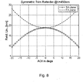
- the SA- and FA-plane net linear retardance profiles for the asymmetric and symmetric TRs are shown in Figs. 7 and 8 , respectively.
- the asymmetric TR shows a peak linear retardance at about 5° AOI.
- the asymmetric retarder will contain a tilted structure, either as an inhomogeneous uniaxial O-plate/- C-plate cascade or a homogeneous tilted biaxial O-plate. Referring to Fig.
- the two-axis profiles of the symmetric TR are mirrored about normal incidence.
- the single-pass transmitted retardance components i.e., linear retardance, linear retarder axis and circular retardance
- the SA orientation of the asymmetric retarder at normal incidence is approximately aligned at -85°, w.r.t. RH-XYZ coordinate system when viewing the beam head-on.
- the SA orientation of the symmetric retarder at normal incidence is approximately aligned at -65°, w.r.t. RH-XYZ coordinate system when viewing the beam head-on.
- the asymmetric TR does not show any significant circular retardance, up to ⁇ 20° AOI over all viewing azimuths.
- the experimental contrast results were collected with a PR-705 spectro-radiometer.
- the VAN-LCoS panel was not driven in the light-off state.
- Tables 4a-d for configurations 500, 520, 540 and 560, respectively.
- the experimental results for configurations 600, 620, 640 and 660 were derived from the configurations for 500, 520, 540, and 560, respectively, taking into account the mirror symmetry in the optical configurations.
- Table 4(a) Experimental contrast measurements in the blue-band for optical configuration 500.
- Configuration 500 TR SA Contrast ratio (asymmetric TR) Contrast ratio (symmetric TR) 506 4100 4400 507 3400 2700 508 4400 4000 509 3700 2600 Table 4(b): Experimental contrast measurements in the blue-band for optical configuration 520.
- Configuration 520 TR SA Contrast ratio (asymmetric TR) Contrast ratio (symmetric TR) 526 3600 3300 527 3300 2400 528 4200 3500 529 3300 2400 Table 4(c): Experimental contrast measurements in the blue-band for optical configuration 540.
- Configuration 540 TR SA Contrast ratio (asymmetric TR) Contrast ratio (symmetric TR) 546 3100 2400 547 4400 3400 548 3200 2300 549 3400 3800 Table 4(d): Experimental contrast measurements in the blue-band for optical configuration 560.
- Configuration 560 TR SA Contrast ratio (asymmetric TR) Contrast ratio (symmetric TR) 566 4000 2200 567 4700 4100 568 3400 2600 569 4300 4500 Table 5(a): Experimental contrast measurements in the blue-band for optical configuration 600.
- Configuration 600 TR SA Contrast ratio (asymmetric TR) Contrast ratio (symmetric TR) 606 3400 2700 607 4100 4400 608 3700 2600 609 4400 4000 Table 5(b): Experimental contrast measurements in the blue-band for optical configuration 620.
- Configuration 620 TR SA Contrast ratio (asymmetric TR) Contrast ratio (symmetric TR) 626 3300 2400 627 3600 3300 628 3300 2400 629 4200 3500 Table 5(c): Experimental contrast measurements in the blue-band for optical configuration 640.
- Configuration 640 TR SA Contrast ratio (asymmetric TR) Contrast ratio (symmetric TR) 646 4400 3400 647 3100 2400 648 3400 3800 649 3200 2300 Table 5(d): Experimental contrast measurements in the blue-band for optical configuration 660.
- Configuration 660 TR SA Contrast ratio (asymmetric TR) Contrast ratio (symmetric TR) 666 4700 4100 667 4000 2200 668 4300 4500 669 3400 2600
- the optimal TR orientation is aligned such that the slow-axis of the trim retarder at normal incidence is closest to the linear polarization input into the system.
- Slow axis orientation here refers to the azimuth with a positive uniaxial director tilt in a RH-XYZ coordinate system and negative uniaxial director tilt in a LH-XYZ coordinate system.
- the SA of the TR is substantially parallel to the incoming linear polarization to the optical system (for example within ⁇ 30° or more preferably within ⁇ 15° of the x-axis in the optical set-ups illustrated here).
- the optimal TR SA location is selected within a particular 1/8 th circle as listed in Table 6(a).
- the optimal SA orientation within one 1/8 th circle region for an asymmetric TR and within two 1/8 th circle regions for a symmetric TR, as outlined in Tables 6a and 6b, respectively, allow for substantially equal image contrast performance regardless of the orientation of WGP and the orientations of LCoS panel SA in a projection system.
- the nominal SA of the VAN-LCoS panel has been nominally pegged at ⁇ 45° and ⁇ 135°. In practice, there is a small tolerance range of this nominal SA orientation. The tolerance is typically within ⁇ 15°, more preferably within ⁇ 10° and still more preferably within ⁇ 5° deviation from the above mentioned VAN-LCoS panel nominal SA orientations. These small azimuthal angle deviations of panel SA orientations from the intended SP-bisector in a given quadrant has no impact on the optimal TR SA orientation regions reported in Table 6(a) and (b).
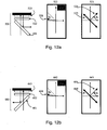
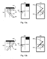
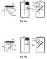
- the optimal range of the TR SA orientation for all four VAN-LCoS panel orientations is shown in Figs. 11a /b, 12a/b, 13a/b, and 14a/b when the TR is an asymmetric TR.
- the TR is an asymmetric TR.
- the choice of this orientation in the shaded region i.e., within the predetermined 1/8 circle) provides an optimal orientation that allows for substantially equal contrast performance with any one of the LCoS panel SA orientations, for both WGP orientations.
- the sole optimal orientation for an asymmetric trim retarder in each optical configuration has its SA azimuthal angle located in a quadrant that is mirrored to the quadrant location of the LCoS panel SA about the y-axis.
- the y-axis is also the axis of rotation for the two WGP orientations ( ⁇ 45° tilt w.r.t. z-axis).
- the optimal TR SA orientation is contained within 1/8 th of the circle, nearest to the incoming polarization axis, in the quadrant that is mirrored to the quadrant location of the LCoS panel SA. This observation is valid for all values of TR A-plate retardance, up to a halfwave. Beyond a halfwave TR A-plate value, the role of slow- and fast-axes switches.
- the asymmetric trim retarder optimally oriented for configurations 500 and 640 i.e., panel orientation #1
- the trim retarder is rotated about the y-axis by 180°.
- the marked SA location is mirrored about the y-axis.
- the SA orientation with reference to positive tilt w.r.t. z-axis
- configurations 520 and 660 i.e., panel orientation #2
- configurations 560 and 620 i.e., panel orientation #4
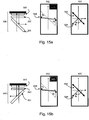
- the graphical representations of the optimal TR SA orientations with a symmetric TR are given in Figs. 15a /b, 16a/b, 17a/b and 18a/b.
- the choice of WGP orientation makes a difference in the absolute contrast numbers at the optimal TR SA locations, when the TR is a symmetric TR.
- the experimental contrast measurements in the blue-band shows a maximum of 3500 for configuration 520 and a maximum of 4500 for configuration 660, both of which use panel orientation #2.
- there is a relatively small difference i.e., between 4200 and 4300 for configurations 520 and 660, respectively.
- the VAN-LCoS panel used in the projection display was modeled as an obliquely aligned LC device (i.e., an O-plate configuration).
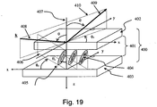
- Fig. 19 shows an example of an LC cell 400 in an obliquely aligned LCoS device.
- the LC layer 401 is sandwiched between a cover glass 402 and a silicon substrate 403.
- Very-large scale integration (VLSI) electronic circuits and optical-quality reflective electrodes are fabricated on the top surface of the substrate 403.
- the applied voltages at the mirrors drive the LC molecules 404, with a counter transparent electrode on the cover glass 402 providing the other electrical contact.
- VLSI Very-large scale integration
- the long-range averaged LC directors 405 are slightly tilted from the device normal (z-direction) 407.
- This polar angle ⁇ c has a projection onto the device plane at an azimuthal angle ⁇ c .
- the azimuthal plane is also the tilt-plane 406.
- the polar angle ⁇ c is a positive angle w.r.t to the +z-axis and is constrained to a value between 0 and 90°.
- the azimuthal angle ⁇ c of the LC director is defined within a 360° range.
- the tilt-plane and the polar angles are shown with a "RH-XYZ" coordinate system in Fig. 19 .
- the pair of ( ⁇ c , ⁇ c ) angles uniquely specifies the orientation of the average LC director.
- the LCoS device is illuminated with a substantially on-axis cone (i.e., the cone axis is parallel to the device normal).
- the plane of incidence 410 contains the wavevector 408 where it is inclined at a polar angle ⁇ w.r.t. the device normal 407.
- a reflective device such as the LCoS, it is convenient to show the viewing angles in a LH-XYZ coordinate system.
- the incident wavevector is reflected as 409. This viewing plane (which is at 180° azimuthal angle difference to the plane of incidence) makes an angle ⁇ v with the x-axis of the LH-XYZ system.
- the pair of ( ⁇ , ⁇ v ) angles uniquely specifies the viewing position.
- the LC mixtures used in the VAN-LCoS panels are positive uniaxial materials with a negative dielectric anisotropy. Some examples of these types of LC mixtures include Merck MLC-6608 and MLC-6610.
- the LC directors are rotated towards the device plane.
- the LC cell is driven below the threshold voltage required for switching or is not driven at all.
- the LC directors are nearly homeotropic in the light-off-state.
- the small pre-tilt angle is typically set to between 5° and 10° to avoid disclination of the LC directors, to be less affected by fringe-field switching, and to speed up the switching response at normal operation.
- the tilt-plane of the VAN-LCoS corresponds to the slow-axis plane.
- the azimuthal angle containing the positive tilt of the LC molecules was determined.
- the LC pre-tilt in VAN-LCoS was assumed homogeneous across the thickness of the cell. For a transmissive device, this O-plate structure does not produce any meaningful circular retardance over the entire viewing cone (for example, up to ⁇ 30° polar angles). However, the homogenous O-plate structure gives rise to measurable circular retardance on reflection.
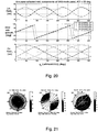
- Fig. 20 illustrates the simulated reflected retardance components of the modeled VAN-LCoS panel for the determination of the slow-axis orientation having the positive tilt. More specifically, Fig. 20 shows a simulation of the VAN-LCoS at 30° AOI for all azimuthal viewing planes. When the viewing plane coincides with the tilt plane, the observer (or the measuring instrument) sees the largest linear retardance but no circular retardance. This is the plane containing the slow-axis of the LC cell. Conversely, when the viewing plane coincides with the fast-axis plane (orthogonal to the tilt plane), the observer sees a dip in the linear retardance while the circular retardance magnitude is the largest.
- Circular retardance is assigned positive and negative signs, associated with left-handed and right-handed circular polarization, respectively. This convention conforms to the natural nomenclature discussed in Yeh et al., "Optics of liquid crystals displays," John Wiley & Sons, New York .
- the plot shows the locations of ⁇ circular retardance signs for [45°, 135°, 225°, 315°] LH-XYZ of LCoS SA orientations (the tilt-plane of the LC having a positive polar angle w.r.t. z-axis).
- Fig. 21 gives the LCoS retardation components for viewing cone up to ⁇ 30° polar angles. These retardance components: linear retardance, retardation axis and circular retardance are shown in (a), (b) and (c), respectively.
- the LC director in the LCoS model is located at 135° (w.r.t. RH-XYZ convention) and thus the SA lies along the north-east/south-west line (w.r.t. LH-XYZ viewing cone). While it is possible to determine the VAN-LCoS tilt plane by the linear retardance map, it is not possible to discern the sense of LC positive vs. negative tilt unless the circular retardance map is utilized.
- the circular retardance magnitude is nearly zero along the SA plane.
- the circular retardance reaches a maximum magnitude.
- the sign of the maximum circular retardance magnitude is positive at 90-deg. CCW viewing azimuth rotation, and negative at 90-deg. CW viewing azimuth rotation, from the VAN-LCoS SA azimuth with positive LC director tilt, (rotation in LH-XYZ coordinate system).
- the magnitude of circular retardance can be measured readily.
- the two-stage model which includes a trim retarder and a VAN-LCoS panel, does not predict the dependencies of compensation efficacy w.r.t. trim retarder SA orientations (i.e., the four possible over-clocking angles provide approximately the same compensation).
- the input polarizer and output analyzer in the model were not birefringent, although suitable polarization extinction ratios were included.
- a wiregrid PBS is utilized to provide for wide wavelength band and wide angle acceptance.
- a second undesirable aspect of the WGP is the phase retardance of the device.
- the WGP is a birefringent device having an effective medium theory (EMT) indicatrix (although its primary function is still one of beam splitter and polarizer).
- EMT effective medium theory
- the WGP indicatrix in projection applications, is tilted from the nominal system XY plane.
- the WGP possesses a birefringence property that impacts the residual retardance compensation of VAN-LCoS panel.
- the very high extinction ratio should eliminate the birefringence effects.
- skew ray effects become a limiting factor in achieving the intrinsic contrast of a TR/LCoS pair.
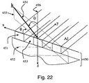
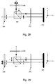
- the modeled wiregrid 450 is shown schematically in Fig. 22 .
- a series of parallel microwires 451 are deposited on a glass substrate 452 to form a one-dimensional grating.
- the grating vector is aligned parallel to the x-axis.
- air 453 fills the gap between the wires.
- the incident wavevector 454 is shown at ⁇ polar angle w.r.t. device normal 456.
- the wavevector is contained within the plane of incidence 455. This plane of incidence makes an azimuthal angle of ⁇ w.r.t. x-axis.
- a RH-XYZ coordinate system is utilized.
- the glass substrate 452 is typically oriented to face the light source (not shown).
- the incoming light is passed through the WGP 450 from glass 452 to grating 451 as a convergent cone.
- the divergent cone is incident on the wire side 451 and the reflection of the wiregrid 451 is deflected towards the analyzer/projection lens.
- the polar and azimuthal angle offsets of the cone illumination, with respect to the WGP device normal are shown in Fig. 23 .
- a f/2.4 cone ⁇ 12° half cone width in air
- the total azimuthal angle range is approximately ⁇ 15.5° (given by arcsine of half-cone width divided by the WGP tilt angle) whereas the largest AOI span ranges from 33° to 57°.
- the AOI range is dependent on the selected viewing azimuth.
- the azimuthal planes are the local planes of incidence.
- each azimuth of samples is maintained, but the ray angles are reduced by Snell's law.
- the cross-section of the cone in the glass medium is oval, with extended cone width along the axis of rotation (y-axis).
- the AOI range along the principal plane of incidence i.e., XZ-plane
- ranges from 21° to 33.5°, approximately, for a glass index of 1.52.
- the microwires are assumed to have 150 nm of width, with 170 nm of depth and 47% duty cycle ratio of wires vs. grating period. There are no additional coating layers above or beneath the wires.
- the model which was modeled using software such as GSolver from Grating Solver Dev. Corp., PO Box 353, Allen, Texas 75013, used a combination of modal-analysis and rigorous coupled-wave analysis to compute the vector diffraction outputs of the wiregrid grating. Owing to the short grating pitch within the visible wavelength band, this grating produced only a zeroth order for both transmission and refection (other orders are evanescent).
- the aluminum wiregrid was modeled as a tabulated list of (n,k) complex indices (e.g., from the Handbook of optical constants of solids, Ed. E.D. Palik, Academic Press, Orlando, 1985 ). Some examples of optical constants for the Al layer, as well as the glass substrate, are provided in Table 7. Table 7: Optical constant of Aluminum layer and Glass substrate used in modelling the WGP. Materials Blue band (450nm) Green band (550nm) Red band (650nm) Al 0.626 - 5.506i 0.974 - 6.723i 1.499 - 7.835i Glass 1.5248 1.5208 1.5158
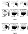
- Figs. 24 and 25 In the first pass through the WGP in transmission (from glass to wires), the diattenuation and retardation components of the transmitted field are shown in Figs. 24 and 25 , respectively.
- the diattenuation components according to these calculation angle ranges are shown in the top half of Fig. 24 , where (a) is a linear diattenuation map, (b) is a transmitted polarizer axis map and (c) is a circular diattenuation map, each map covering at least f/2.4 sampling cone for transmission from glass to wiregrid.
- This segment of the viewing cone is slightly larger than the refracted (actual) cone in glass (the actual refracted cone in Fig. 23 is at tangent to the four sides of the cone segment centered at device-normal). The sharp corners of the segment do not represent ray angles in the actual cone of light and these data points are. ⁇ neglected
- the diattenuation components within the viewing cone are shown in the bottom half of Fig. 24 , where (d) is a linear diattenuation map, (e) is a transmitted polarizer axis map, and (f) is a circular diattenuation map, each map covering only the required f/2.4 sampling cone for transmission from glass to wiregrid. These latter three viewing cone coordinates are referenced to the cone-axis in air.
- the linear diattenuation of the WGP in transmission is very high, nearly 100% as shown in Fig. 24(d) .
- the linear diattenuation axis is termed 'higher-amplitude' axis (HA), to avoid the confusion of transmission and absorption axes used in traditional absorptive and wiregrid reflective polarizers.
- HA 'higher-amplitude' axis
- Fig. 24(e) indicates that there could be as much as ⁇ 1.7° of diattenuator axis change, for a typical f/2.4 cone in air.
- the circular diattenuation picks up at non-principal plane incidences.
- the circular diattenuation of the WGP in transmission reaches approximately ⁇ 3.4%.
- Fig. 25 The corresponding simulated retardation results are shown in Fig. 25 , including a linear retardance map (a), a slow axis map (b), and a circular retardance map (c), where each map covers the required sampling f/2.4 cone.
- the linear retardance magnitude is rather uniform at any viewing position.
- the slow axis map indicates a similar, but not identical, distribution of linear retarder axis distribution when compared to linear diattenuator axis distribution.
- the slow axis is distributed over 90° ⁇ 2.5° within an equivalent of f/2.4 cone in air.
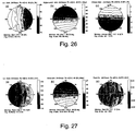
- the polar decomposition method adopted here assumes a diattenuator followed by a retarder.
- the linear diattenuation map (a) shows that the linear diattenuation is now severely dependent on the view cone position (ranging from approximately 78% to 87% from the largest AOI to the smallest AOI, or about 57° to 33° AOI in air).
- the slow axis map (b) shows that the linear diattenuator axis ranges up to ⁇ 4.7°, within the f/2.4 cone (vs. ⁇ 1.7° range in the first pass).
- the circular diattenuation map (c) shows that the circular diattenuation is also of larger magnitude than the circular diattenuation in the transmitted first pass, at up to ⁇ 6.1 % within the f/2.4 cone.
- the significantly poorer reflection diattenuation characteristics are compounded by poor reflection retardation properties.
- the tilt of the wiregrid equivalent indicatrix has been aligned at about + 45° w.r.t. system XY plane. Note that, the simulation has been performed as a convergent cone.
- the second pass at the WGP uses a divergent cone, this means the diattenuation and retardation properties are rotated by 180° azimuth, about its cone axis.
- the slow-axis distribution of the reflected field (b) varies up to ⁇ 3.8°, slightly worse than the transmitted first pass, whereas circular retardance (c) is not present in the reflected field.
- the birefringence compensation in a VAN-LCoS based projection system is appreciably affected by the presence of a WGP at a nominal ⁇ 45° tilt w.r.t. system z-axis.
- the first pass through the wiregrid (from glass to aluminum), introduces non-negligible circular retardance into the already linearly polarized light beam.
- the retardation property of the WGP in transmission resembles a negative uniaxial A-plate (with a very small optic axis tilt). This property has been exploited such that the WGP is rotated in-plane, and used as a compensator.
- trim retarder element that also shows viewing-cone dependent circular retardance
- some orientations of the trim retarder element would be less optimal when the sign of the circular retardance in each quadrant of the viewing cone is not arranged appropriately. This explains the variations in the actual compensated panel contrast values, obtained with a symmetric retarder having non-negligible circular retardance.
- the trim retarder should be oriented appropriately in order to realize the very high system contrast ratios.
- the retardation properties of the WGP at ⁇ 45° tilt w.r.t. z-axis are rather dispersive with wavelength of operation.
- the reflected field of the WGP has an associated equivalent O-plate birefringence.
- the trim retarder is clocked to an optimal azimuthal orientation such that the overall system contrast is substantially unaffected by the azimuthal location of the slow axis in the liquid crystal display panel and/or the orientation of the WGP.
- the measured contrast levels listed in Tables 4a-d include 4100, 4400, 3600, 4200, 4400, 3400, 4700, and 4300 for the four different panel orientations.
- the difference in measured contrast levels is further reduced by selecting the starting over-clocking angle to be in a quadrant that is mirrored to the quadrant location of the SA of the LCD panel about an axis perpendicular to the polarization axis of the incident light (i.e., the y-axis).
- the measured contrast levels include 4100, 4200, 4400, and 4300.
- the trim retarder in each of these four configurations is clocked to an optimal azimuthal orientation that results in an overall system contrast that is substantially unaffected by the azimuthal location of the slow axis in the liquid crystal display panel.
- the measured contrast levels listed in Tables 5a-d include 4100, 4400, 3600, 4200, 4400, 3400, 4700, and 4300 for four different panel orientations. Again, this difference in measured contrast levels is further reduced by selecting the starting over-clocking angle to be in a quadrant that is mirrored to the quadrant location of the SA of the LCD panel about an axis perpendicular to the polarization axis of the incident light (i.e., the y-axis).
- the resulting contrast levels are measured as 4400, 4300, 4100, and 4200.
- the trim retarder in each of these four configurations is also clocked to an optimal azimuthal orientation that results in an overall system contrast that is substantially unaffected by the azimuthal location of the slow axis in the liquid crystal display panel.
- the instant invention results in a commercially valuable optimization technique that results in consistent overall system contrast levels, thus standardizing the contrast ratio of the product. More specifically, the optimization technique allows a set of trim retarders, diced with their SA oriented in the appropriate optimal region, to be used for differently oriented LCD panels and/or oriented WGPs, in the same or different projection systems, while still maintaining similar contrast levels.
- the optimization technique provided by the instant invention is significantly different than experimentally determining the azimuthal orientation of the trim retarder that corresponds to the highest overall system contrast.
- the optimal azimuthal angle of an asymmetric trim retarder for a LCoS in panel orientation #1 is between 0 and -44°, regardless of the orientation of the WGP (e.g., this produces similar contrast levels of 4100 and 4400 for configurations 500 and 640, respectively).
- the highest experimental contrast measurement for panel orientation #1 and a WGP orientated at -45° is 4400 for trim retarder SA orientation 508, which is between 136 and 180°.
- the measured contrast levels listed in Tables 4a-d are 4400, 4000, 3300, 3500, 3400, 3800, 4100, and 4500 for the four panel orientations and a wire grid orientation of -45°.
- These measured contrast ratios provide a maximum variation of 1200 compared to the maximum variation of 2300 (i.e., orientations 566 vs. 569) when the slow axis of the trim retarder is arbitrarily selected.
- the trim retarder in each of these eight configurations is said to be clocked to an optimal azimuthal orientation that provides an overall system contrast that is substantially unaffected by the azimuthal location of the slow axis of the liquid crystal display panel.
- the measured contrast levels listed in Tables 5a-d are 4400, 4000, 3300, 3500, 3400, 3800, 4100, and 4500 for the four panel orientations and a wire grid orientation of +45°. These measured contrast ratios provide a maximum variation of 1200 compared to the maximum variation of 2300 (i.e., configuration 667 vs. 668) when the slow axis of the trim retarder is arbitrarily selected.
- the trim retarder in each of these eight configurations is said to be clocked to an optimal azimuthal orientation that provides an overall system contrast that is substantially unaffected by the azimuthal location of the slow axis of the liquid crystal display panel.
- the orientation of the WGP plays an important role in determining the overall system contrast when the trim retarder is asymmetric.
- an asymmetric trim retarder selected to compensate for a specific type of LCD panel is positioned between a WGP and the LCD panel and is rotated such that its slow axis is within a predetermined optimal range selected in dependence upon the orientation of the slow axis of the LCD panel. For example, if the slow axis of the LCD panel corresponds to panel orientation #1, then the predetermined optimal range will be between 0 and -44°, whereas if the slow axis of the LCD panel corresponds to panel orientation #2, #3, or #4, then the predetermined optimal range will be between 136 and 180°, -136 and -180°, and 0 and 44°, respectively.
- the trim retarder is clocked to the exact optimal azimuthal angle (e.g., using a calculated over-clocking angle and/or experimental fine tuning).
- a second asymmetric trim retarder manufactured with the same parameters as the first trim retarder is positioned between a second WGP and a second LCD panel and is rotated such that its slow axis is within a second predetermined optimal range selected in dependence upon the orientation of the slow axis of the second LCD panel.
- the first and second trim retarders, WGPs, and LCD panels are either part of different projection systems or different color channels in the same projection system. With regard to the latter, different color channels may have differently oriented WGPs and/or differently oriented LCD panels.
- this optimization technique results in an overall system contrast is substantially unaffected by the slow axis orientation of the first and second LCDs and/or the orientation of the two WGPs.
- suitable materials for the asymmetric trim retarder include a) liquid crystal polymer configured as a uniaxial O-plate, with an optional -C-plate element such as a form birefringence coating, b) tilted discotic (negative) uniaxial O-plate (such as Fuji Wideview film) where the -C-plate element is integrated homogeneously with the O-plate element, c) tilted negative biaxial organic foil, such as cellulose acetate compound, where the c-axis of the biaxial medium is tilted from the device normal, d) birefringent crystal (solid) configured as an O-plate (having one or more layers), both positive and negative birefringence crystal may be applicable, e) obliquely coated inorganic thin-film retarder where the resultant equivalent index indicatrix is a tilted uniaxial or biaxial birefringence, and/or f) distorted (or deformed) helix ferroelectric liquid crystal polymer where each LC director is tilt
- a symmetric trim retarder can be selected to compensate for a specific type of LCD panel is positioned between the WGP and the LCD panel and can be rotated such that its slow axis is within one of two predetermined optimal ranges selected in dependence upon the orientation of the slow axis of the LCD panel.
- the two predetermined optimal ranges will be 0 to -44° and 136 to 180°
- the predetermined optimal ranges will be 0 to -44° and 136 to 180°, 0 to 44° and - 136 to -180°, and 0 to 44° and -136 to -180°, respectively.
- the trim retarder is clocked to the exact optimal azimuthal angle (e.g., using a calculated over-clocking angle and/or experimental fine tuning).
- a second symmetric trim retarder manufactured with the same parameters as the first trim retarder is positioned between a second WGP and a second LCD panel and is rotated such that its slow axis is within one of two predetermined optimal ranges selected in dependence upon the orientation of the slow axis of the second LCD panel.
- the first and second trim retarders, WGPs, and LCD panels are either part of different projection systems or different color channels in the same projection system. With regard to the latter, different color channels may have differently oriented WGPs and/or differently oriented LCD panels.
- this optimization technique results in an overall system contrast is substantially unaffected by the slow axis orientation of the first and second LCDs and/or the orientation of the WGPs.
- suitable symmetric trim retarders include a) liquid crystal polymer retarder configured as an uniaxial A-plate (optic axis in the plane of the trim retarder device), with an optional -C-plate element such as form birefringence elements, b) a zero-order grating (ZOG) where the grating pitch is substantially shorter than the wavelength of illumination and the grating is equivalent to an effective form-birefringence medium having its optic axis aligned in the plane of the retarder device (where the ZOG may be written on a UV-sensitive layer, with E-beam encoding, or photoresist patterning and etching of suitable substrate or coated materials), c) non-tilted organic biaxial organic foil, such as cellulose acetate compound, where the c-axis of the biaxial medium is parallel to the display system z-axis, d) Birefringent crystals (solid) configured as an A-plate, both positive and negative birefringence crystal may be applicable, and/or
- the present invention has been described with reference to subsystems including a pre-polarizer, a WGP, a trim retarder, a VAN-mode LCoS panel, and a clean-up polarizer 204, for exemplary purposes.
- a pre-polarizer for exemplary purposes.
- WGP Wood-Green-Glass
- trim retarder for exemplary purposes.
- VAN-mode LCoS panel for exemplary purposes.
- clean-up polarizer 204 for exemplary purposes.
- the instant invention provides an optimization technique for compensators in microdisplay projection systems that use a MacNeille-type or 3M polymer-film polarization beam splitter (PBS) cube 501 rather than a WGP (wherein the coated tilted hypotenuse of the PBS gives rise to an asymmetric EMF indicatrix).
- PBS MacNeille-type or 3M polymer-film polarization beam splitter
- the optimal range for the trim retarder SA may vary for different embodiments.
- the optimal range for the trim retarder SA will be closer to the second linear polarization (i.e., orthogonal to the incoming polarization). Accordingly, the scope of the invention is therefore intended to be limited solely by the scope of the appended claims.
Landscapes
- Physics & Mathematics (AREA)
- Nonlinear Science (AREA)
- General Physics & Mathematics (AREA)
- Optics & Photonics (AREA)
- Chemical & Material Sciences (AREA)
- Crystallography & Structural Chemistry (AREA)
- Mathematical Physics (AREA)
- Engineering & Computer Science (AREA)
- Multimedia (AREA)
- Signal Processing (AREA)
- Liquid Crystal (AREA)
- Projection Apparatus (AREA)
- Polarising Elements (AREA)
- Transforming Electric Information Into Light Information (AREA)
Claims (12)
- Un système de projection à base d'affichage à cristaux liquides comprenant :une source de lumière ;un diviseur de faisceau de polarisation (201) conçu pour recevoir de la lumière provenant de la source de lumière et pour transmettre une première lumière polarisée de façon linéaire ayant une première lumière polarisée de façon linéaire (241, 242) ayant un axe de polarisation linéaire correspondant à l'axe X d'un système de coordonnées XYZ à droite avec des axes orthogonaux ;un panneau d'affichage à cristaux liquides réfléchissant (203) conçu pour moduler de façon optique la première lumière polarisée de façon linéaire, le panneau d'affichage à cristaux liquides ayant un axe lent (220) et un axe rapide (221) ;le diviseur de faisceau de polarisation étant conçu pour recevoir la lumière modulée de façon optique (243) et pour faire dévier une deuxième lumière polarisée de façon linéaire (244) ayant un deuxième axe de polarisation linéaire correspondant à l'axe Y, une lentille de projection conçue pour projeter la deuxième lumière polarisée de façon linéaire sur un écran ; etun ajusteur de retard (202) disposé entre le panneau d'affichage à cristaux liquides et le diviseur de faisceau de polarisation, l'ajusteur de retard ayant un retardement dans le plan supérieur à un retardement résiduel dans le plan du panneau d'affichage à cristaux liquides et ayant un axe lent (230),dans lequel l'angle azimutal de l'axe lent de l'ajusteur de retard est inférieur à 45 degrés à partir du premier axe de polarisation linéaire ;caractérisé en ce que l'ajusteur de retard a un profil asymétrique de retardement linéaire net par rapport à un angle d'incidence, lorsque mesuré le long du plan d'axe lent de l'ajusteur de retard ;dans lequel l'ajusteur de retard est orienté de telle sorte qu'un angle azimutal de l'axe lent de l'ajusteur de retard soit dans un quadrant qui reflète un quadrant contenant l'axe lent du panneau d'affichage à cristaux liquides autour du deuxième axe de polarisation linéaire, pour fournir un niveau de contraste de système qui n'est substantiellement pas affecté par au moins soit des orientations différentes de l'axe lent du panneau d'affichage à cristaux liquides, soit des orientations différentes du diviseur de faisceau de polarisation,dans lequel chacune desdites orientations différentes de l'axe lent du panneau d'affichage à cristaux liquides divise substantiellement en deux les premier et deuxième axes de polarisation linéaires dans un quadrant différent du panneau d'affichage à cristaux liquides etdans lequel chacune desdites orientations différentes du diviseur de faisceau de polarisation est de +45 degrés ou -45 degrés par rapport à l'axe Z.
- Le système de projection à base d'affichage à cristaux liquides selon la revendication 1, dans lequel le diviseur de faisceau de polarisation est un cube diviseur de faisceau de polarisation de type MacNeille.
- Le système de projection à base d'affichage à cristaux liquides selon la revendication 1, dans lequel le diviseur de faisceau de polarisation est un polariseur à grille de fil métallique orienté à une incidence éloignée de la normale.
- Le système de projection à base d'affichage à cristaux liquides selon la revendication 3, comprenant un pré-polariseur (200) conçu pour transmettre la première lumière polarisée de façon linéaire (241) à un premier côté du polariseur à grille de fil métallique et un polariseur de nettoyage (204) conçu pour recevoir la deuxième lumière polarisée de façon linéaire (244) réfléchie à partir d'un deuxième côté opposé du polariseur à grille de fil métallique.
- Le système de projection à base d'affichage à cristaux liquides selon la revendication 3, dans lequel le panneau d'affichage à cristaux liquides comprend un cristal liquide nématique verticalement aligné sur un panneau en silicium.
- Le système de projection à base de cristaux liquides selon n'importe lesquelles des revendications 1 à 5, dans lequel l'angle azimutal est inférieur à 30 degrés à partir du premier axe de polarisation linéaire.
- Une méthode de synchronisation de l'ajusteur de retard dans un système de projection à base de dispositif d'affichage à cristaux liquides selon la revendication 1, la méthode comprenant :le fait de fournir l'ajusteur de retard (202) pour compenser un retardement résiduel dans le plan du panneau d'affichage à cristaux liquides (203),le fait de déterminer une première étendue d'angle azimutal pour l'angle azimutal de l'axe lent du premier ajusteur de retard, la première étendue d'angle azimuta étant sélectionnée pour fournir un tel niveau de contraste de système ;le fait d'orienter l'ajusteur de retard de telle façon que l'angle azimutal de son axe lent soit compris dans les limites de la première étendue d'angle azimutal,dans laquelle le fait de déterminer la première étendue d'angle azimuta inclut le fait de sélectionner la première étendue d'angle azimuta pour qu'elle soit comprise entre 0 et 44° à partir du premier axe de polarisation linéaire.
- Une méthode selon la revendication 7, comprenant :le fait de fournir un deuxième ajusteur de retard pour compenser un retardement résiduel dans le plan d'un deuxième panneau d'affichage à cristaux liquides, le deuxième ajusteur de retard ayant un retardement dans le plan supérieur au retardement résiduel dans le plan du deuxième panneau d'affichage à cristaux liquides et ayant un axe lent ;le fait de déterminer une deuxième étendue d'angle azimutal pour un angle azimutal de l'axe lent du deuxième ajusteur de retard, la deuxième étendue d'angle azimuta étant sélectionnée pour fournir ledit niveau de contraste de système ; etle fait d'orienter le deuxième ajusteur de retard de telle façon que l'angle azimutal de son axe lent soit compris dans les limites de la deuxième étendue d'angle azimutal.
- Une méthode selon la revendication 8, dans laquelle le diviseur de faisceau de polarisation comprend un polariseur à grille de fil métallique et le panneau d'affichage à cristaux liquides comprend un cristal liquide nématique verticalement aligné sur un panneau en silicium.
- Une méthode selon la revendication 7, dans laquelle le fait de déterminer la première étendue d'angle azimutal inclut le fait de calculer quatre angles de sur-synchronisation possibles et le fait de sélectionner la première étendue d'angle azimuta pour exclure des angles de sur-synchronisation qui fournissent les niveaux de contraste de système qui dépendent le plus de l'orientation du diviseur de faisceau de polarisation.
- Une méthode selon la revendication 7, dans laquelle le fait de déterminer la première étendue d'angle azimuta inclut le fait de sélectionner la première étendue d'angle azimutal pour qu'elle soit comprise entre 0 et 30° à partir du premier axe de polarisation linéaire.
- Une méthode selon la revendication 8, dans laquelle les premier et deuxième retardateurs de compensation sont fabriqués avec substantiellement les mêmes paramètres.
Applications Claiming Priority (2)
| Application Number | Priority Date | Filing Date | Title |
|---|---|---|---|
| US71582905P | 2005-09-09 | 2005-09-09 | |
| US73711305P | 2005-11-16 | 2005-11-16 |
Publications (3)
| Publication Number | Publication Date |
|---|---|
| EP1764644A2 EP1764644A2 (fr) | 2007-03-21 |
| EP1764644A3 EP1764644A3 (fr) | 2007-10-24 |
| EP1764644B1 true EP1764644B1 (fr) | 2017-08-30 |
Family
ID=37684078
Family Applications (1)
| Application Number | Title | Priority Date | Filing Date |
|---|---|---|---|
| EP06254535.5A Not-in-force EP1764644B1 (fr) | 2005-09-09 | 2006-08-31 | Compensateurs de retardation orientés de maniere optimale |
Country Status (4)
| Country | Link |
|---|---|
| US (1) | US7714945B2 (fr) |
| EP (1) | EP1764644B1 (fr) |
| JP (1) | JP5095162B2 (fr) |
| CN (1) | CN1928632B (fr) |
Families Citing this family (56)
| Publication number | Priority date | Publication date | Assignee | Title |
|---|---|---|---|---|
| JP4661510B2 (ja) * | 2005-10-03 | 2011-03-30 | 日本ビクター株式会社 | 投射表示装置及び3板式液晶プロジェクタ |
| KR100976623B1 (ko) * | 2006-09-08 | 2010-08-18 | 주식회사 엘지화학 | 반사형 편광판을 사용한 거울형 액정 디스플레이 장치 |
| JP2008216867A (ja) * | 2007-03-07 | 2008-09-18 | Sanyo Electric Co Ltd | 投写型表示装置 |
| EP1980902B1 (fr) * | 2007-04-10 | 2015-07-15 | JDS Uniphase Corporation | Compensation de contraste xLCD nématique en hélice avec retardateurs de plaque inclinée |
| USRE44483E1 (en) | 2007-06-20 | 2013-09-10 | Reald Inc. | ZSCREEN® modulator with wire grid polarizer for stereoscopic projection |
| US7633666B2 (en) * | 2007-06-20 | 2009-12-15 | Real D | ZScreen® modulator with wire grid polarizer for stereoscopic projection |
| CN101918880B (zh) * | 2008-01-22 | 2014-03-26 | 阿尔卡特朗讯美国公司 | 用于光学图像投影的光调制器 |
| US20090213281A1 (en) * | 2008-02-26 | 2009-08-27 | Young Garrett J | System and method for improved contrast ratio in a projection system |
| CN102725688B (zh) * | 2009-07-10 | 2015-04-01 | 管理前街不同收入阶层的前街投资管理有限公司 | 使用单成像路径生成三维图像信息的方法和装置 |
| EP2282231A3 (fr) * | 2009-08-07 | 2011-05-04 | JDS Uniphase Corporation | Retardement optique multi-segments pour la création d'images 3D |
| CN102483566B (zh) * | 2009-09-11 | 2015-11-25 | 汤姆森许可贸易公司 | 三维(3d)投影的方法和系统 |
| JP5573197B2 (ja) | 2010-01-27 | 2014-08-20 | セイコーエプソン株式会社 | 反射型液晶プロジェクター |
| JP5471674B2 (ja) | 2010-03-23 | 2014-04-16 | セイコーエプソン株式会社 | プロジェクター |
| CN102096187B (zh) * | 2010-12-23 | 2014-10-15 | 福建福晶科技股份有限公司 | 一种宽带消色差索利尔-巴比涅补偿器 |
| JP5703774B2 (ja) * | 2011-01-21 | 2015-04-22 | セイコーエプソン株式会社 | プロジェクター |
| JP5930600B2 (ja) * | 2011-04-08 | 2016-06-08 | キヤノン株式会社 | 偏光分離素子および画像投射装置 |
| US8867001B2 (en) | 2011-06-13 | 2014-10-21 | Benq Materials Corp. | Patterned retardation film comprising relief-like stripe structures and sub micron grooves |
| TWI450780B (zh) * | 2011-07-07 | 2014-09-01 | Benq Materials Corp | 用於製造相位差薄膜之滾輪的製造方法及使用該滾輪的相位差膜製造方法與相位差膜 |
| CN203405635U (zh) * | 2013-09-05 | 2014-01-22 | 深圳市时代华影科技开发有限公司 | 一种低投射比高光效立体投影装置及立体投影系统 |
| EP3369034B1 (fr) | 2015-10-26 | 2023-07-05 | RealD Spark, LLC | Système de confidentialité intelligent, appareil et procédé associés |
| US11079619B2 (en) | 2016-05-19 | 2021-08-03 | Reald Spark, Llc | Wide angle imaging directional backlights |
| KR101915843B1 (ko) * | 2016-06-29 | 2018-11-08 | 한국과학기술원 | 복굴절 매질을 이용한 영상 깊이 추정 방법 및 장치 |
| US10126575B1 (en) | 2017-05-08 | 2018-11-13 | Reald Spark, Llc | Optical stack for privacy display |
| EP3622342A4 (fr) | 2017-05-08 | 2021-02-17 | RealD Spark, LLC | Empilement optique pour affichage directionnel |
| JP6575563B2 (ja) | 2017-06-29 | 2019-09-18 | セイコーエプソン株式会社 | 液晶表示装置および電子機器 |
| TW201921060A (zh) | 2017-09-15 | 2019-06-01 | 美商瑞爾D斯帕克有限責任公司 | 用於可切換定向顯示器的光學堆疊結構 |
| US10948648B2 (en) | 2017-09-29 | 2021-03-16 | Reald Spark, Llc | Backlights having stacked waveguide and optical components with different coefficients of friction |
| US11109014B2 (en) | 2017-11-06 | 2021-08-31 | Reald Spark, Llc | Privacy display apparatus |
| EP3710889B1 (fr) * | 2017-11-17 | 2023-07-26 | Meta Platforms Technologies, LLC | Commutateur de retard à cristaux liquides à compensation automatique |
| US10976578B2 (en) | 2018-01-25 | 2021-04-13 | Reald Spark, Llc | Reflective optical stack for privacy display |
| JP7353007B2 (ja) | 2018-01-25 | 2023-09-29 | リアルディー スパーク エルエルシー | プライバシー表示用タッチスクリーン |
| KR20200141459A (ko) | 2018-03-22 | 2020-12-18 | 리얼디 스파크, 엘엘씨 | 지향성 백라이트용 광학 도파관 |
| US11079645B2 (en) | 2018-06-29 | 2021-08-03 | Reald Spark, Llc | Stabilization for privacy display |
| CN112602011A (zh) | 2018-07-18 | 2021-04-02 | 瑞尔D斯帕克有限责任公司 | 用于可切换定向显示器的光学堆叠 |
| JP7177617B2 (ja) * | 2018-07-24 | 2022-11-24 | スタンレー電気株式会社 | ランプユニット、車両用灯具システム |
| US11106103B2 (en) | 2018-10-03 | 2021-08-31 | Reald Spark, Llc | Privacy display apparatus controlled in response to environment of apparatus |
| TW202107181A (zh) | 2018-11-07 | 2021-02-16 | 美商瑞爾D斯帕克有限責任公司 | 定向顯示裝置 |
| US11287677B2 (en) | 2019-01-07 | 2022-03-29 | Reald Spark, Llc | Optical stack for privacy display |
| WO2020167680A1 (fr) | 2019-02-12 | 2020-08-20 | Reald Spark, Llc | Diffuseur pour afficheur de confidentialité |
| CN110261317B (zh) * | 2019-06-17 | 2021-11-16 | 西安理工大学 | 一种Mueller矩阵光谱的测量系统及方法 |
| TW202102883A (zh) | 2019-07-02 | 2021-01-16 | 美商瑞爾D斯帕克有限責任公司 | 定向顯示設備 |
| CN114174903A (zh) * | 2019-07-26 | 2022-03-11 | 奇跃公司 | 面板延迟测量 |
| JP2022543020A (ja) | 2019-08-02 | 2022-10-07 | リアルディー スパーク エルエルシー | プライバシーディスプレイ用光学スタック |
| US11114063B2 (en) | 2019-10-02 | 2021-09-07 | Reald Spark, Llc | Privacy display apparatus |
| KR20220098382A (ko) | 2019-11-13 | 2022-07-12 | 리얼디 스파크, 엘엘씨 | 축외 디스플레이 디바이스 |
| EP4025952A4 (fr) * | 2019-11-22 | 2023-11-08 | Valve Corporation | Visiocasque (hmd) comprenant une optique à retardateur variant dans l'espace |
| WO2021118936A1 (fr) | 2019-12-10 | 2021-06-17 | Reald Spark, Llc | Contrôle du reflet d'un dispositif d'affichage |
| EP4078254A4 (fr) | 2019-12-18 | 2023-11-01 | RealD Spark, LLC | Commande de lumière ambiante pour un dispositif d'affichage de confidentialité |
| EP4143632A1 (fr) | 2020-04-30 | 2023-03-08 | RealD Spark, LLC | Appareil d'affichage directionnel |
| CN115867854A (zh) | 2020-04-30 | 2023-03-28 | 瑞尔D斯帕克有限责任公司 | 定向显示设备 |
| WO2021222606A1 (fr) | 2020-04-30 | 2021-11-04 | Reald Spark, Llc | Appareil d'affichage directionnel |
| TW202204818A (zh) | 2020-07-29 | 2022-02-01 | 美商瑞爾D斯帕克有限責任公司 | 光瞳照明裝置 |
| EP4189285A1 (fr) | 2020-07-29 | 2023-06-07 | RealD Spark, LLC | Rétroéclairage pour affichage directionnel commutable |
| US11892717B2 (en) | 2021-09-30 | 2024-02-06 | Reald Spark, Llc | Marks for privacy display |
| US11977286B2 (en) | 2022-02-09 | 2024-05-07 | Reald Spark, Llc | Observer-tracked privacy display |
| WO2023196440A1 (fr) | 2022-04-07 | 2023-10-12 | Reald Spark, Llc | Appareil d'affichage directionnel |
Family Cites Families (51)
| Publication number | Priority date | Publication date | Assignee | Title |
|---|---|---|---|---|
| US2478385A (en) | 1946-12-07 | 1949-08-09 | Libbey Owens Ford Glass Co | Multilayer low light reflecting film |
| US3185020A (en) | 1961-09-07 | 1965-05-25 | Optical Coating Laboratory Inc | Three layer anti-reflection coating |
| US3463574A (en) | 1967-06-26 | 1969-08-26 | Perkin Elmer Corp | Multilayer antireflection coating for low index materials |
| US3604784A (en) | 1969-01-21 | 1971-09-14 | Bausch & Lomb | Antireflection coatings |
| US3565509A (en) | 1969-03-27 | 1971-02-23 | Bausch & Lomb | Four layered antireflection coatings |
| US3936136A (en) | 1970-12-29 | 1976-02-03 | Nippon Kogaku K.K. | Multilayer anti-reflection film for ultraviolet rays |
| FR2149311B1 (fr) | 1971-08-19 | 1974-05-10 | Anvar | |
| JPS5310861B2 (fr) | 1972-04-26 | 1978-04-17 | ||
| US3781090A (en) | 1972-11-06 | 1973-12-25 | Minolta Camera Kk | Four layer anti-reflection coating |
| US4313647A (en) | 1975-12-23 | 1982-02-02 | Mamiya Koki Kabushiki Kaisha | Nonreflective coating |
| US4666250A (en) | 1985-04-16 | 1987-05-19 | Rockwell International Corporation | Interference filter design using flip-flop optimization |
| EP0379315B1 (fr) | 1989-01-19 | 1994-05-18 | Seiko Epson Corporation | Dispositif d'affichage électro-optique à cristal liquide |
| JP2565563B2 (ja) | 1989-03-18 | 1996-12-18 | 株式会社日立製作所 | 液晶表示装置の製法および液晶表示装置用位相板の製法 |
| JP2558905B2 (ja) * | 1990-02-01 | 1996-11-27 | シャープ株式会社 | 液晶表示装置 |
| US5184237A (en) | 1990-03-27 | 1993-02-02 | Ricoh Company, Ltd. | Super-twisted nematic type liquid crystal display device |
| US5196953A (en) | 1991-11-01 | 1993-03-23 | Rockwell International Corporation | Compensator for liquid crystal display, having two types of layers with different refractive indices alternating |
| FR2693020B1 (fr) * | 1992-06-26 | 1999-01-22 | Thomson Consumer Electronics | Dispositif d'affichage a cristal liquide nematique en helice. |
| JP2624116B2 (ja) | 1993-04-22 | 1997-06-25 | 松下電器産業株式会社 | 液晶表示装置およびそれを用いた投写型表示装置 |
| US5986733A (en) * | 1993-04-30 | 1999-11-16 | Rockwell International Corporation | Negative optical compensator tilted in respect to liquid crystal cell for liquid crystal display |
| JP2968152B2 (ja) * | 1993-07-27 | 1999-10-25 | シャープ株式会社 | 液晶表示装置 |
| JP3041169B2 (ja) * | 1993-09-14 | 2000-05-15 | シャープ株式会社 | 液晶表示装置 |
| EP0725942B1 (fr) | 1994-08-23 | 2003-07-16 | Koninklijke Philips Electronics N.V. | Dispositif d'affichage a cristaux liquides et feuille retardatrice |
| US5638200A (en) | 1995-02-03 | 1997-06-10 | Ois Optical Imaging Systems, Inc. | Liquid crystal display with tilted retardation film |
| JP3776126B2 (ja) | 1995-02-23 | 2006-05-17 | コーニンクレッカ フィリップス エレクトロニクス エヌ ヴィ | 液晶ディスプレイ装置及びリタルデーション箔 |
| JP3462334B2 (ja) * | 1995-03-08 | 2003-11-05 | セイコーエプソン株式会社 | 投写型表示装置 |
| JPH10161106A (ja) * | 1996-11-28 | 1998-06-19 | Matsushita Electric Ind Co Ltd | 投写型液晶表示装置 |
| GB2321529A (en) | 1997-01-24 | 1998-07-29 | Sharp Kk | Broadband cholesteric optical device |
| JPH10282487A (ja) | 1997-02-05 | 1998-10-23 | Sharp Corp | 液晶表示素子 |
| US5895106A (en) | 1997-06-13 | 1999-04-20 | Ois Optical Imaging Systems, Inc. | NW twisted nematic LCD with negative tilted retarders on one side of liquid crystal cell |
| FR2781892B1 (fr) | 1998-07-28 | 2002-08-30 | Sextant Avionique | Amelioration de l'angle de vue d'un ecran lcd par nouvel empilement de films birefringents |
| JP2000347177A (ja) * | 1999-03-29 | 2000-12-15 | Minolta Co Ltd | 表示光学装置及びそれを用いたプロジェクター表示装置 |
| JP4367585B2 (ja) | 1999-07-27 | 2009-11-18 | ソニー株式会社 | 液晶プロジェクタ装置 |
| EP1212655B1 (fr) | 1999-09-16 | 2015-01-07 | Merck Patent GmbH | Compensateur optique et dispositif d'affichage a cristaux liquides i |
| US6590707B1 (en) | 2000-03-31 | 2003-07-08 | 3M Innovative Properties Company | Birefringent reflectors using isotropic materials and form birefringence |
| US6587172B1 (en) * | 2000-05-03 | 2003-07-01 | Three-Five Systems, Inc. | Controlled angle retarder with liquid crystal cell bias tuned for a sequence of wavelengths |
| JP3724335B2 (ja) * | 2000-05-31 | 2005-12-07 | ソニー株式会社 | 液晶プロジェクタ装置及びコントラストの改善方法 |
| EP1160617B1 (fr) | 2000-05-31 | 2004-10-13 | Sony Corporation | Projecteur à cristaux liquides à contraste amélioré |
| JP2002072209A (ja) | 2000-08-28 | 2002-03-12 | Sharp Corp | 液晶表示装置 |
| US6585378B2 (en) | 2001-03-20 | 2003-07-01 | Eastman Kodak Company | Digital cinema projector |
| ATE392093T1 (de) * | 2001-06-11 | 2008-04-15 | 3M Innovative Properties Co | Projektionssystem mit geringem astigmatismus |
| US6857747B2 (en) | 2001-08-06 | 2005-02-22 | Advanced Digital Optics, Inc. | Color management system |
| US6909473B2 (en) | 2002-01-07 | 2005-06-21 | Eastman Kodak Company | Display apparatus and method |
| US7006184B2 (en) * | 2002-04-12 | 2006-02-28 | Eastman Kodak Company | Bend aligned namatic liquid crystal imaging display with compensation film |
| US6805445B2 (en) * | 2002-06-05 | 2004-10-19 | Eastman Kodak Company | Projection display using a wire grid polarization beamsplitter with compensator |
| JP2004126496A (ja) * | 2002-08-05 | 2004-04-22 | Hitachi Ltd | 光学ユニット及びそれを用いた投射型映像表示装置 |
| JP4386407B2 (ja) | 2002-11-20 | 2009-12-16 | 富士フイルム株式会社 | 位相差補償システム及び液晶プロジェクタ |
| US6950454B2 (en) * | 2003-03-24 | 2005-09-27 | Eastman Kodak Company | Electronic imaging system using organic laser array illuminating an area light valve |
| US6805924B1 (en) | 2003-04-14 | 2004-10-19 | Eastman Kodak Company | Compensation films for LCD |
| EP1542044A1 (fr) * | 2003-12-11 | 2005-06-15 | JDS Uniphase Corporation | Compensateurs de retardation comprenant une biréfringence négative |
| US7626661B2 (en) | 2003-12-11 | 2009-12-01 | Jds Uniphase Corporation | Polarization controlling elements |
| JP3972371B2 (ja) * | 2005-03-15 | 2007-09-05 | ソニー株式会社 | 位相差補償板、位相差補償器、液晶表示装置および投射型画像表示装置 |
-
2006
- 2006-08-31 US US11/468,860 patent/US7714945B2/en active Active
- 2006-08-31 EP EP06254535.5A patent/EP1764644B1/fr not_active Not-in-force
- 2006-09-06 JP JP2006241082A patent/JP5095162B2/ja not_active Expired - Fee Related
- 2006-09-11 CN CN2006101269735A patent/CN1928632B/zh not_active Expired - Fee Related
Non-Patent Citations (1)
| Title |
|---|
| None * |
Also Published As
| Publication number | Publication date |
|---|---|
| JP5095162B2 (ja) | 2012-12-12 |
| EP1764644A3 (fr) | 2007-10-24 |
| CN1928632A (zh) | 2007-03-14 |
| US20070064163A1 (en) | 2007-03-22 |
| JP2007094399A (ja) | 2007-04-12 |
| CN1928632B (zh) | 2012-03-28 |
| EP1764644A2 (fr) | 2007-03-21 |
| US7714945B2 (en) | 2010-05-11 |
Similar Documents
| Publication | Publication Date | Title |
|---|---|---|
| EP1764644B1 (fr) | Compensateurs de retardation orientés de maniere optimale | |
| US7518662B2 (en) | Contrast enhancement for liquid crystal based projection systems | |
| TWI427374B (zh) | 遲延度補償元件、垂直配向向列型液晶顯示裝置、及液晶投影機 | |
| JP2007094399A5 (fr) | ||
| JP4608459B2 (ja) | 傾斜cプレート・リターダおよびそれを組み込んだディスプレイ・システム | |
| US7345723B2 (en) | LC panel compensators | |
| US8537310B2 (en) | Polarization-independent liquid crystal display devices including multiple polarization grating arrangements and related devices | |
| WO2019090246A1 (fr) | Appareil d'affichage de confidentialité | |
| JP4805130B2 (ja) | 反射型液晶表示素子及び反射型液晶プロジェクタ | |
| JP2009545773A (ja) | 形態複屈折型偏光ビームスプリッタを用いたLCoSプロジェクションシステム用の補償スキーム | |
| EP1980902B1 (fr) | Compensation de contraste xLCD nématique en hélice avec retardateurs de plaque inclinée | |
| EP2141533B1 (fr) | Compensation de contraste de panneaux à micro-affichage incluant une lame de retardement d'ordre supérieur | |
| KR20110105351A (ko) | 액정 장치 및 투사형 표시 장치 | |
| WO2007021981A2 (fr) | Amelioration de contrastes pour des systemes de projection fondes sur des cristaux liquides | |
| US11796828B2 (en) | Control of reflections of a display device | |
| JP2003322853A (ja) | プロジェクタ | |
| CN113646695A (zh) | 用于防窥显示器的漫射器 |
Legal Events
| Date | Code | Title | Description |
|---|---|---|---|
| PUAI | Public reference made under article 153(3) epc to a published international application that has entered the european phase |
Free format text: ORIGINAL CODE: 0009012 |
|
| AK | Designated contracting states |
Kind code of ref document: A2 Designated state(s): AT BE BG CH CY CZ DE DK EE ES FI FR GB GR HU IE IS IT LI LT LU LV MC NL PL PT RO SE SI SK TR |
|
| AX | Request for extension of the european patent |
Extension state: AL BA HR MK YU |
|
| PUAL | Search report despatched |
Free format text: ORIGINAL CODE: 0009013 |
|
| AK | Designated contracting states |
Kind code of ref document: A3 Designated state(s): AT BE BG CH CY CZ DE DK EE ES FI FR GB GR HU IE IS IT LI LT LU LV MC NL PL PT RO SE SI SK TR |
|
| AX | Request for extension of the european patent |
Extension state: AL BA HR MK YU |
|
| 17P | Request for examination filed |
Effective date: 20080423 |
|
| 17Q | First examination report despatched |
Effective date: 20080521 |
|
| AKX | Designation fees paid |
Designated state(s): AT BE BG CH CY CZ DE DK EE ES FI FR GB GR HU IE IS IT LI LT LU LV MC NL PL PT RO SE SI SK TR |
|
| RAP1 | Party data changed (applicant data changed or rights of an application transferred) |
Owner name: VIAVI SOLUTIONS INC. |
|
| RIC1 | Information provided on ipc code assigned before grant |
Ipc: H04N 9/31 20060101ALI20160922BHEP Ipc: G02B 5/30 20060101ALI20160922BHEP Ipc: G02F 1/1362 20060101ALN20160922BHEP Ipc: G02F 1/13363 20060101AFI20160922BHEP Ipc: G02F 1/139 20060101ALI20160922BHEP |
|
| GRAP | Despatch of communication of intention to grant a patent |
Free format text: ORIGINAL CODE: EPIDOSNIGR1 |
|
| STAA | Information on the status of an ep patent application or granted ep patent |
Free format text: STATUS: GRANT OF PATENT IS INTENDED |
|
| INTG | Intention to grant announced |
Effective date: 20161111 |
|
| RIC1 | Information provided on ipc code assigned before grant |
Ipc: G02F 1/13363 20060101AFI20161028BHEP Ipc: G02F 1/1362 20060101ALN20161028BHEP Ipc: G02F 1/139 20060101ALI20161028BHEP Ipc: G02B 5/30 20060101ALI20161028BHEP Ipc: H04N 9/31 20060101ALI20161028BHEP |
|
| GRAJ | Information related to disapproval of communication of intention to grant by the applicant or resumption of examination proceedings by the epo deleted |
Free format text: ORIGINAL CODE: EPIDOSDIGR1 |
|
| STAA | Information on the status of an ep patent application or granted ep patent |
Free format text: STATUS: EXAMINATION IS IN PROGRESS |
|
| INTC | Intention to grant announced (deleted) | ||
| GRAP | Despatch of communication of intention to grant a patent |
Free format text: ORIGINAL CODE: EPIDOSNIGR1 |
|
| STAA | Information on the status of an ep patent application or granted ep patent |
Free format text: STATUS: GRANT OF PATENT IS INTENDED |
|
| RIC1 | Information provided on ipc code assigned before grant |
Ipc: H04N 9/31 20060101ALI20170307BHEP Ipc: G02F 1/139 20060101ALI20170307BHEP Ipc: G02F 1/13363 20060101AFI20170307BHEP Ipc: G02B 5/30 20060101ALI20170307BHEP Ipc: G02F 1/1362 20060101ALN20170307BHEP |
|
| RIC1 | Information provided on ipc code assigned before grant |
Ipc: G02B 5/30 20060101ALI20170315BHEP Ipc: H04N 9/31 20060101ALI20170315BHEP Ipc: G02F 1/13363 20060101AFI20170315BHEP Ipc: G02F 1/139 20060101ALI20170315BHEP Ipc: G02F 1/1362 20060101ALN20170315BHEP |
|
| INTG | Intention to grant announced |
Effective date: 20170327 |
|
| GRAS | Grant fee paid |
Free format text: ORIGINAL CODE: EPIDOSNIGR3 |
|
| GRAA | (expected) grant |
Free format text: ORIGINAL CODE: 0009210 |
|
| STAA | Information on the status of an ep patent application or granted ep patent |
Free format text: STATUS: THE PATENT HAS BEEN GRANTED |
|
| AK | Designated contracting states |
Kind code of ref document: B1 Designated state(s): AT BE BG CH CY CZ DE DK EE ES FI FR GB GR HU IE IS IT LI LT LU LV MC NL PL PT RO SE SI SK TR |
|
| REG | Reference to a national code |
Ref country code: GB Ref legal event code: FG4D |
|
| REG | Reference to a national code |
Ref country code: CH Ref legal event code: EP |
|
| REG | Reference to a national code |
Ref country code: AT Ref legal event code: REF Ref document number: 924125 Country of ref document: AT Kind code of ref document: T Effective date: 20170915 |
|
| REG | Reference to a national code |
Ref country code: IE Ref legal event code: FG4D |
|
| REG | Reference to a national code |
Ref country code: DE Ref legal event code: R096 Ref document number: 602006053455 Country of ref document: DE |
|
| PGFP | Annual fee paid to national office [announced via postgrant information from national office to epo] |
Ref country code: GB Payment date: 20170830 Year of fee payment: 12 |
|
| REG | Reference to a national code |
Ref country code: NL Ref legal event code: MP Effective date: 20170830 |
|
| REG | Reference to a national code |
Ref country code: LT Ref legal event code: MG4D |
|
| REG | Reference to a national code |
Ref country code: AT Ref legal event code: MK05 Ref document number: 924125 Country of ref document: AT Kind code of ref document: T Effective date: 20170830 |
|
| PG25 | Lapsed in a contracting state [announced via postgrant information from national office to epo] |
Ref country code: AT Free format text: LAPSE BECAUSE OF FAILURE TO SUBMIT A TRANSLATION OF THE DESCRIPTION OR TO PAY THE FEE WITHIN THE PRESCRIBED TIME-LIMIT Effective date: 20170830 Ref country code: LT Free format text: LAPSE BECAUSE OF FAILURE TO SUBMIT A TRANSLATION OF THE DESCRIPTION OR TO PAY THE FEE WITHIN THE PRESCRIBED TIME-LIMIT Effective date: 20170830 Ref country code: SE Free format text: LAPSE BECAUSE OF FAILURE TO SUBMIT A TRANSLATION OF THE DESCRIPTION OR TO PAY THE FEE WITHIN THE PRESCRIBED TIME-LIMIT Effective date: 20170830 Ref country code: FI Free format text: LAPSE BECAUSE OF FAILURE TO SUBMIT A TRANSLATION OF THE DESCRIPTION OR TO PAY THE FEE WITHIN THE PRESCRIBED TIME-LIMIT Effective date: 20170830 |
|
| PG25 | Lapsed in a contracting state [announced via postgrant information from national office to epo] |
Ref country code: IS Free format text: LAPSE BECAUSE OF FAILURE TO SUBMIT A TRANSLATION OF THE DESCRIPTION OR TO PAY THE FEE WITHIN THE PRESCRIBED TIME-LIMIT Effective date: 20171230 Ref country code: ES Free format text: LAPSE BECAUSE OF FAILURE TO SUBMIT A TRANSLATION OF THE DESCRIPTION OR TO PAY THE FEE WITHIN THE PRESCRIBED TIME-LIMIT Effective date: 20170830 Ref country code: GR Free format text: LAPSE BECAUSE OF FAILURE TO SUBMIT A TRANSLATION OF THE DESCRIPTION OR TO PAY THE FEE WITHIN THE PRESCRIBED TIME-LIMIT Effective date: 20171201 Ref country code: LV Free format text: LAPSE BECAUSE OF FAILURE TO SUBMIT A TRANSLATION OF THE DESCRIPTION OR TO PAY THE FEE WITHIN THE PRESCRIBED TIME-LIMIT Effective date: 20170830 Ref country code: BG Free format text: LAPSE BECAUSE OF FAILURE TO SUBMIT A TRANSLATION OF THE DESCRIPTION OR TO PAY THE FEE WITHIN THE PRESCRIBED TIME-LIMIT Effective date: 20171130 |
|
| REG | Reference to a national code |
Ref country code: DE Ref legal event code: R119 Ref document number: 602006053455 Country of ref document: DE |
|
| REG | Reference to a national code |
Ref country code: CH Ref legal event code: PL |
|
| PG25 | Lapsed in a contracting state [announced via postgrant information from national office to epo] |
Ref country code: NL Free format text: LAPSE BECAUSE OF FAILURE TO SUBMIT A TRANSLATION OF THE DESCRIPTION OR TO PAY THE FEE WITHIN THE PRESCRIBED TIME-LIMIT Effective date: 20170830 |
|
| PG25 | Lapsed in a contracting state [announced via postgrant information from national office to epo] |
Ref country code: RO Free format text: LAPSE BECAUSE OF FAILURE TO SUBMIT A TRANSLATION OF THE DESCRIPTION OR TO PAY THE FEE WITHIN THE PRESCRIBED TIME-LIMIT Effective date: 20170830 Ref country code: CZ Free format text: LAPSE BECAUSE OF FAILURE TO SUBMIT A TRANSLATION OF THE DESCRIPTION OR TO PAY THE FEE WITHIN THE PRESCRIBED TIME-LIMIT Effective date: 20170830 Ref country code: CH Free format text: LAPSE BECAUSE OF NON-PAYMENT OF DUE FEES Effective date: 20170831 Ref country code: PL Free format text: LAPSE BECAUSE OF FAILURE TO SUBMIT A TRANSLATION OF THE DESCRIPTION OR TO PAY THE FEE WITHIN THE PRESCRIBED TIME-LIMIT Effective date: 20170830 Ref country code: DK Free format text: LAPSE BECAUSE OF FAILURE TO SUBMIT A TRANSLATION OF THE DESCRIPTION OR TO PAY THE FEE WITHIN THE PRESCRIBED TIME-LIMIT Effective date: 20170830 Ref country code: LI Free format text: LAPSE BECAUSE OF NON-PAYMENT OF DUE FEES Effective date: 20170831 |
|
| REG | Reference to a national code |
Ref country code: IE Ref legal event code: MM4A |
|
| PG25 | Lapsed in a contracting state [announced via postgrant information from national office to epo] |
Ref country code: IT Free format text: LAPSE BECAUSE OF FAILURE TO SUBMIT A TRANSLATION OF THE DESCRIPTION OR TO PAY THE FEE WITHIN THE PRESCRIBED TIME-LIMIT Effective date: 20170830 Ref country code: SK Free format text: LAPSE BECAUSE OF FAILURE TO SUBMIT A TRANSLATION OF THE DESCRIPTION OR TO PAY THE FEE WITHIN THE PRESCRIBED TIME-LIMIT Effective date: 20170830 Ref country code: EE Free format text: LAPSE BECAUSE OF FAILURE TO SUBMIT A TRANSLATION OF THE DESCRIPTION OR TO PAY THE FEE WITHIN THE PRESCRIBED TIME-LIMIT Effective date: 20170830 Ref country code: MC Free format text: LAPSE BECAUSE OF FAILURE TO SUBMIT A TRANSLATION OF THE DESCRIPTION OR TO PAY THE FEE WITHIN THE PRESCRIBED TIME-LIMIT Effective date: 20170830 |
|
| REG | Reference to a national code |
Ref country code: BE Ref legal event code: MM Effective date: 20170831 |
|
| PG25 | Lapsed in a contracting state [announced via postgrant information from national office to epo] |
Ref country code: LU Free format text: LAPSE BECAUSE OF NON-PAYMENT OF DUE FEES Effective date: 20170831 |
|
| PLBE | No opposition filed within time limit |
Free format text: ORIGINAL CODE: 0009261 |
|
| STAA | Information on the status of an ep patent application or granted ep patent |
Free format text: STATUS: NO OPPOSITION FILED WITHIN TIME LIMIT |
|
| RAP2 | Party data changed (patent owner data changed or rights of a patent transferred) |
Owner name: VIAVI SOLUTIONS INC. |
|
| PG25 | Lapsed in a contracting state [announced via postgrant information from national office to epo] |
Ref country code: IE Free format text: LAPSE BECAUSE OF NON-PAYMENT OF DUE FEES Effective date: 20170831 Ref country code: DE Free format text: LAPSE BECAUSE OF NON-PAYMENT OF DUE FEES Effective date: 20180301 |
|
| 26N | No opposition filed |
Effective date: 20180531 |
|
| REG | Reference to a national code |
Ref country code: FR Ref legal event code: ST Effective date: 20180716 |
|
| PG25 | Lapsed in a contracting state [announced via postgrant information from national office to epo] |
Ref country code: SI Free format text: LAPSE BECAUSE OF FAILURE TO SUBMIT A TRANSLATION OF THE DESCRIPTION OR TO PAY THE FEE WITHIN THE PRESCRIBED TIME-LIMIT Effective date: 20170830 Ref country code: BE Free format text: LAPSE BECAUSE OF NON-PAYMENT OF DUE FEES Effective date: 20170831 |
|
| PG25 | Lapsed in a contracting state [announced via postgrant information from national office to epo] |
Ref country code: FR Free format text: LAPSE BECAUSE OF NON-PAYMENT OF DUE FEES Effective date: 20171030 |
|
| GBPC | Gb: european patent ceased through non-payment of renewal fee |
Effective date: 20180831 |
|
| PG25 | Lapsed in a contracting state [announced via postgrant information from national office to epo] |
Ref country code: HU Free format text: LAPSE BECAUSE OF FAILURE TO SUBMIT A TRANSLATION OF THE DESCRIPTION OR TO PAY THE FEE WITHIN THE PRESCRIBED TIME-LIMIT; INVALID AB INITIO Effective date: 20060831 |
|
| PG25 | Lapsed in a contracting state [announced via postgrant information from national office to epo] |
Ref country code: GB Free format text: LAPSE BECAUSE OF NON-PAYMENT OF DUE FEES Effective date: 20180831 Ref country code: CY Free format text: LAPSE BECAUSE OF NON-PAYMENT OF DUE FEES Effective date: 20170830 |
|
| PG25 | Lapsed in a contracting state [announced via postgrant information from national office to epo] |
Ref country code: TR Free format text: LAPSE BECAUSE OF FAILURE TO SUBMIT A TRANSLATION OF THE DESCRIPTION OR TO PAY THE FEE WITHIN THE PRESCRIBED TIME-LIMIT Effective date: 20170830 |
|
| PG25 | Lapsed in a contracting state [announced via postgrant information from national office to epo] |
Ref country code: PT Free format text: LAPSE BECAUSE OF FAILURE TO SUBMIT A TRANSLATION OF THE DESCRIPTION OR TO PAY THE FEE WITHIN THE PRESCRIBED TIME-LIMIT Effective date: 20170830 |