EP1764231A2 - Düsenauftragssystem für Klebstoff - Google Patents
Düsenauftragssystem für Klebstoff Download PDFInfo
- Publication number
- EP1764231A2 EP1764231A2 EP06120570A EP06120570A EP1764231A2 EP 1764231 A2 EP1764231 A2 EP 1764231A2 EP 06120570 A EP06120570 A EP 06120570A EP 06120570 A EP06120570 A EP 06120570A EP 1764231 A2 EP1764231 A2 EP 1764231A2
- Authority
- EP
- European Patent Office
- Prior art keywords
- adhesive
- application
- application system
- nozzle opening
- opening
- Prior art date
- Legal status (The legal status is an assumption and is not a legal conclusion. Google has not performed a legal analysis and makes no representation as to the accuracy of the status listed.)
- Withdrawn
Links
Images




Classifications
-
- B—PERFORMING OPERATIONS; TRANSPORTING
- B42—BOOKBINDING; ALBUMS; FILES; SPECIAL PRINTED MATTER
- B42C—BOOKBINDING
- B42C9/00—Applying glue or adhesive peculiar to bookbinding
- B42C9/0006—Applying glue or adhesive peculiar to bookbinding by applying adhesive to a stack of sheets
-
- B—PERFORMING OPERATIONS; TRANSPORTING
- B05—SPRAYING OR ATOMISING IN GENERAL; APPLYING FLUENT MATERIALS TO SURFACES, IN GENERAL
- B05C—APPARATUS FOR APPLYING FLUENT MATERIALS TO SURFACES, IN GENERAL
- B05C5/00—Apparatus in which liquid or other fluent material is projected, poured or allowed to flow on to the surface of the work
- B05C5/001—Apparatus in which liquid or other fluent material is projected, poured or allowed to flow on to the surface of the work incorporating means for heating or cooling the liquid or other fluent material
-
- B—PERFORMING OPERATIONS; TRANSPORTING
- B05—SPRAYING OR ATOMISING IN GENERAL; APPLYING FLUENT MATERIALS TO SURFACES, IN GENERAL
- B05C—APPARATUS FOR APPLYING FLUENT MATERIALS TO SURFACES, IN GENERAL
- B05C5/00—Apparatus in which liquid or other fluent material is projected, poured or allowed to flow on to the surface of the work
- B05C5/02—Apparatus in which liquid or other fluent material is projected, poured or allowed to flow on to the surface of the work the liquid or other fluent material being discharged through an outlet orifice by pressure, e.g. from an outlet device in contact or almost in contact, with the work
- B05C5/0225—Apparatus in which liquid or other fluent material is projected, poured or allowed to flow on to the surface of the work the liquid or other fluent material being discharged through an outlet orifice by pressure, e.g. from an outlet device in contact or almost in contact, with the work characterised by flow controlling means, e.g. valves, located proximate the outlet
- B05C5/0229—Apparatus in which liquid or other fluent material is projected, poured or allowed to flow on to the surface of the work the liquid or other fluent material being discharged through an outlet orifice by pressure, e.g. from an outlet device in contact or almost in contact, with the work characterised by flow controlling means, e.g. valves, located proximate the outlet the valve being a gate valve or a sliding valve
- B05C5/0233—Apparatus in which liquid or other fluent material is projected, poured or allowed to flow on to the surface of the work the liquid or other fluent material being discharged through an outlet orifice by pressure, e.g. from an outlet device in contact or almost in contact, with the work characterised by flow controlling means, e.g. valves, located proximate the outlet the valve being a gate valve or a sliding valve rotating valve, e.g. rotating perforated cylinder
-
- B—PERFORMING OPERATIONS; TRANSPORTING
- B05—SPRAYING OR ATOMISING IN GENERAL; APPLYING FLUENT MATERIALS TO SURFACES, IN GENERAL
- B05C—APPARATUS FOR APPLYING FLUENT MATERIALS TO SURFACES, IN GENERAL
- B05C5/00—Apparatus in which liquid or other fluent material is projected, poured or allowed to flow on to the surface of the work
- B05C5/02—Apparatus in which liquid or other fluent material is projected, poured or allowed to flow on to the surface of the work the liquid or other fluent material being discharged through an outlet orifice by pressure, e.g. from an outlet device in contact or almost in contact, with the work
- B05C5/0254—Coating heads with slot-shaped outlet
- B05C5/0258—Coating heads with slot-shaped outlet flow controlled, e.g. by a valve
-
- B—PERFORMING OPERATIONS; TRANSPORTING
- B05—SPRAYING OR ATOMISING IN GENERAL; APPLYING FLUENT MATERIALS TO SURFACES, IN GENERAL
- B05C—APPARATUS FOR APPLYING FLUENT MATERIALS TO SURFACES, IN GENERAL
- B05C5/00—Apparatus in which liquid or other fluent material is projected, poured or allowed to flow on to the surface of the work
- B05C5/02—Apparatus in which liquid or other fluent material is projected, poured or allowed to flow on to the surface of the work the liquid or other fluent material being discharged through an outlet orifice by pressure, e.g. from an outlet device in contact or almost in contact, with the work
- B05C5/0254—Coating heads with slot-shaped outlet
- B05C5/0266—Coating heads with slot-shaped outlet adjustable in length, e.g. for coating webs of different width
Definitions
- the invention relates to an application system for adhesive according to the preamble of patent claim 1.
- adhesive is either applied to a book spine using roller applicators or alternatively with application nozzles.
- the adhesive is dispersion adhesives, hot melt adhesives or dispersion / hot melt adhesive combinations.
- the adhesive polyurethane PUR for short
- PUR polyurethane
- This adhesive is also advantageous for poorer paper quality, with poorer paper quality meant as coated papers in which the proportion of coating ingredients outweighs the fiber content required for the strength, and also roughen poorer to expose the fiber for bonding.
- nozzle application systems are also increasingly being used, such as in the US Pat US Pat. No. 4,667,879 , of the European patent application EP 1 033 262 and the European patent application EP 550 913 shown. All of these publications are mean that after Because of the desire to vary the width of the adhesive trace. This is important for nozzles, since, unlike in a roller application system, the adhesive outside the surface to be bonded can not flow back into the system and so contamination of the system or a higher-level device can not be avoided if the nozzle is set too wide.
- the US 4,667,879 solves this problem of width adjustment of the adhesive track through a cylindrical adhesive chamber in which a cylindrical metering roller is arranged, wherein the cylindrical metering roller has a recess on the circumference, which has different lengths in the axial direction, in particular has the shape of a trapezoid.
- the cylindrical metering roller has a recess on the circumference, which has different lengths in the axial direction, in particular has the shape of a trapezoid.
- This device is particularly suitable for very long traces of glue, such as can be used in wood processing.
- the system is intended for regular hot glue, which does not show the problem of the ausreagierenden adhesive to the extent.
- a coating system for adhesive with a cylindrical adhesive chamber wherein within the cylindrical adhesive chamber, a cylindrical metering roller is arranged, wherein the cylindrical metering roller has a recess on the circumference, which has different length in the axial direction, such as a trapezoid, a rhombus , an oval or a triangle, wherein the recess of the cylindrical metering roller interacts with the application nozzle openings of the application system, wherein the length of the recess in the axial direction which is opposite theminutedüsenö Maschinen, the adhesive application width of theaiddüsenö réelle is substantially predetermined, with the characterizing features of claim 1 solved. Further features emerge from the subclaims and the following description of preferred embodiments.
- the application system according to the invention has closure means for the application nozzle opening.
- the closure means of the application nozzle opening is a two-part nozzle plate having at least one closure edge, wherein the closure edge is slidably disposed relative to the applicator nozzle opening, such that overlapping the closure edge and the applicator nozzle opening Adhesive flow can be interrupted.
- the two-part nozzle plate be designed such that both parts of the two-part nozzle plate are movable to bring the sealing edge on the applicator nozzle opening and close tightly or part of the two-part nozzle plate is stationary.
- the closure means of the application nozzle opening is a one-piece nozzle plate having at least one nozzle plate opening, wherein the nozzle plate opening is slidably disposed relative to the applicator nozzle opening, such that only at an at least partial overlap of the nozzle plate opening and the application nozzle opening can flow adhesive.
- the nozzle plate opening is slidably disposed relative to the applicator nozzle opening, such that only at an at least partial overlap of the nozzle plate opening and the application nozzle opening can flow adhesive.
- An advantage of using a one-piece or two-part nozzle plate is that this nozzle plate can be very thin and thus little space between the nozzle opening and the medium to which the adhesive is applied, such as a book block is needed.
- One possible adjusting means of the nozzle plate which realizes the displacement between the nozzle plate opening and the application nozzle opening, can be arranged further away from the application nozzle opening, at a location where more space is available for this purpose.
- the nozzle plate opening consists of a double row of mutually offset holes, through which the adhesive flows depending on the application width during application. This leads to a stabilization of the nozzle plate, because no continuous slot along the application width is required.
- a seal which terminates with the cylindrical adhesive chamber is arranged on the metering roller along the depression.
- the seal is advantageously such to ensure that it also protrudes into the applicator nozzle opening so far as to prevent a lateral wide flow of the adhesive in the nozzle.
- the application nozzle opening advantageously has a weakening at this point.
- a lubricating grease is applied in the side area between the cylindrical adhesive chamber and the metering roller outside the depression, which has high-viscosity properties at the temperature of the hot adhesive.
- the temperature at which PUR is processed is about 130 ° C.
- the metering roller and / or the cylindrical adhesive chamber is covered with adhesion-reducing materials or constructed of materials with low adhesion, such as PTFE (polytetrafluoroethylene, Teflon). This promotes the possibility of quickly cleaning the application system.
- adhesion-reducing materials such as PTFE (polytetrafluoroethylene, Teflon).
- the application head 10 of the application system 100 can be seen in section.
- the application head 10 has a cylindrical adhesive chamber 11, within which the metering roller 20 is arranged. Through an adhesive inlet opening 12, adhesive 2 is introduced into the adhesive chamber 11.
- the metering roller 20 is, as shown in Fig. 2, constructed such that it has a recess 22 on its periphery.
- This recess 22 may have different geometric shapes, such as a triangle, a trapezoid, a rhombus, an oval or other shape, these forms of the recess 22 is common that the width of the recess 22 is different in the axial direction.
- the recess 22 is bounded laterally by sealing rings 26a, 26b.
- 20 further sealing rings 26 b are mounted on the metering roll, which also complete the side portion 23 between the recess and the edge of the metering roller 20.
- a highly viscous lubricating grease is applied, especially one which is highly viscous at the operating temperature of the nozzle roller, for example at 130 ° C for PUR.
- the metering roller 20 is rotatable about its axis in the direction of the double arrow marked with the reference numeral 25.
- a drive 28 serves this purpose.
- At least one heating element 40 is arranged.
- a higher-level controller 50 controls both the drive 28 for adjusting the metering roller 20 and the control of the heating element 40 to keep the metering roller 20 at the desired operating temperature.
- the adhesive 2 flows into the recess 22 on the metering roller 20 and leaves the applicator head 10 through the applicator nozzle opening 16 to be applied as a glue trace 2 on a book spine of a book block 1.
- a weakening 14 is provided below the application nozzle opening 16, which reduces the thickness of the application head 10 in the region of the application nozzle opening 16 to a minimum.
- the sealing rings 26a come as close as possible to the application nozzle opening 16 in order to prevent the adhesive track 2 from flowing on the book block 1.
- a nozzle plate 32, 33 is arranged between the book block 1 and the application nozzle opening 16, a nozzle plate 32, 33 is arranged.
- An adjustment means 30, which is also controlled by the controller 50, is capable of displacing the nozzle plate 32, 33 relative to the applicator nozzle opening 16 such that opening or closing of the applicator nozzle opening 16 is possible so as to meter the adhesive 2 onto the book block 1 to ensure. In addition, this can complete the system 100 at rest against the outside atmosphere.
- Fig. 3 is a detail view of a two-part nozzle plate 33 is shown.
- the application nozzle opening 16 is closed by the closing edge 37 of the movable part of the two-part nozzle plate 33.
- an opening angle ⁇ is also shown, which is provided between the application plane and the two-part nozzle plate 33.
- a pull-wedge 36 which is used for sensitive adjustment and adjustment of the clear width of the gap in the two-part nozzle plate.
- FIGS. 5 and 6 show a further embodiment of the application device 100 according to the invention, wherein a one-piece nozzle plate 32 is attached above the application nozzle opening 16 by means of screws 35.
- a valve 18 is shown, which regulates the flow of adhesive into the adhesive chamber 11.
- the one-piece nozzle plate 32 has a slot 38, in a different embodiment shown in FIG. 8a a double row 39 consisting of spaced holes 39a of diameter D and distance A from center to center within a row, wherein the distance A is less than two distances D, so that over the entire width of the double row 39 adhesive 2 can flow.
- This embodiment with the holes 39a has a higher stability than a continuous slot 38.
- an opening angle ⁇ is also provided between the one-piece nozzle plate 32 and the application level, which prevents the adhesive trace 2 from coming into contact with the application head 10 after application to the book block 1.
- deviationating from circular holes 39a other shapes are conceivable, such as triangles or hexagonal openings.
- the one-piece nozzle plate 32 can be easily removed by loosening the screws 35 from the applicator head 10 to clean or replace it.
- the application system 100 has been described in particular in connection with the adhesive binding of book blocks 1, but can also be used in other applications in which a defined amount of adhesive must be applied in different widths to a surface, for example in wood processing.
Landscapes
- Coating Apparatus (AREA)
Abstract
Description
- Die Erfindung betrifft ein Auftragssystem für Klebstoff gemäß dem Oberbegriff von Patentanspruch 1.
- Bei der Buchherstellung im Klebebindeverfahren wird Klebstoff entweder mit Walzenauftragswerken auf einen Buchrücken aufgetragen oder alternativ mit Auftragsdüsen. Bei dem Klebstoff handelt es sich dabei um Dispersionsklebstoffe, Schmelzklebstoffe oder Dispersions-Schmelzklebstoff-Kombinationen. Dabei hat sich in den letzten Jahren der Klebstoff Polyurethan (kurz: PUR) als Schmelzklebstoff herausgestellt, der eine besonders gute Blattausreißfestigkeit aufweist sowie bei dem Buchblock 180° Aufschlagverhalten, dem so genannten Lay-Flat-Verhalten besonders vorteilhafte Ergebnisse erzielt. Dieser Klebstoff ist auch für schlechtere Papierqualität vorteilhaft einsetzbar, wobei bei schlechterer Papierqualität etwa gestrichene Papiere gemeint, bei denen der Anteil der Strichbestandteile den für die Festigkeit erforderlichen Faseranteil überwiegt, und die sich auch schlechter aufrauen lassen, um die Faser für die Verklebung freizulegen.
- Problematisch bei dem Einsatz von PUR ist die nur begrenzte Einsatzfähigkeit für Walzenauftragswerke, da die relativ dünnen Klebeschichten von wenigen 100 Mikrometern in einem Walzenauftragswerk technisch nur schwer beherrschbar sind, sowie der Einstell-, Bedien- und Reinigungsaufwand sehr hoch ist. Überdies setzt der Klebstoff im Kontakt mit der Umgebung gesundheitsschädliche Isocyanate frei, was ebenfalls die Einsatzfähigkeit des PUR-Klebstoffs für Walzenauftragswerke einschränkt. Zudem härtet das PUR an einer Sauerstoffatmosphäre und unter Einfluss von Luftfeuchtigkeit vorzeitig aus, insbesondere bei traditionellen Walzenauftragswerken, die eine große Oberfläche gegenüber der Atmosphäre aufweisen. Dieser Nachteil der Walzenauftragswerke zeigt sich insbesondere bei Kleinauflagen und häufig wechselnden Papiersorten, wie diese durch den Digitaldruck in zunehmendem Maße entstehen. Um diese Nachteile zu umgehen, werden zunehmend auch Düsenauftragssysteme verwendet, etwa wie in dem
US-Patent US 4,667,879 , derEuropäischen Patentanmeldung EP 1 033 262 und der Europäischen PatentanmeldungEP 550 913 - Die
US 4,667,879 löst dieses Problem der Breitenanpassung der Klebstoffspur durch eine zylindrische Klebstoffkammer, in der eine zylindrische Dosierwalze angeordnet ist, wobei die zylindrische Dosierwalze am Umfang eine Vertiefung aufweist, die in axialer Richtung unterschiedliche Längen hat, insbesondere die Form eines Trapezes aufweist. Je nach Drehwinkel der Dosierwalze ist damit nur die der entsprechenden Breite der Vertiefung auf der Dosierwalze zugeordnete Auftragsdüsenöffnung für den Klebstoff zugänglich, so dass entsprechend nur in diesem Bereich Klebstoff durch die Düse austreten kann, der Rest wird durch die Seitenbereiche der Dosierwalze versperrt. Diese Vorrichtung eignet sich besonders für sehr lange Leimspuren, wie sie etwa bei der Holzverarbeitung verwendet werden können. Überdies ist das System für regulären Heißleim gedacht, bei dem sich die Problematik des ausreagierenden Klebstoffes nicht in dem Maße zeigt. - In der
EP 1 033 262 ist ein anderes Düsenauftragssystem gezeigt, bei dem die Düsenbreite über einen Schieber der oberhalb der Düse angeordnet ist, hervorragt. Zudem ist ein Verschluss der Düsenöffnung vorgesehen, der allerdings unterhalb der Düsenöffnung liegt und damit nur schwer zugänglich ist. Problematisch am Stand der Technik gemäß derUS 4,667,879 ist es, dass für ein Verschlussmittel der Düsenöffnung gemäß derEP 1 033 262 kein ausreichender Platz vorhanden ist. - Es ist daher die Aufgabe der Erfindung, ein Auftragssystem zu schaffen, das auf einfache Weise Klebstoffspuren einer bestimmten, einstellbaren Breite auf Materialien, insbesondere Buchblöcke, aufbringen kann, das für PUR geeignet ist und Mittel aufweist, die ein vorzeitiges Ausreagieren des PUR-Klebstoffes verhindern, um so die Standzeit des PURs im Auftragssystem zu verlängern, die Reinigung des Systems zu erleichtern sowie die Länge einer Klebstoffspur auf einfache Weise zu dosieren.
- Diese Aufgabe wird mit einem Auftragssystem für Klebstoff mit einer zylindrischen Klebstoffkammer, wobei innerhalb der zylindrischen Klebstoffkammer eine zylindrische Dosierwalze angeordnet ist, wobei die zylindrische Dosierwalze am Umfang eine Vertiefung aufweist, die in axialer Richtung unterschiedliche Länge aufweist, etwa in Form eines Trapezes, einer Raute, eines Ovals oder eines Dreiecks, wobei die Vertiefung der zylindrischen Dosierwalze mit den Auftragsdüsenöffnungen des Auftragssystems wechselwirkt, wobei durch die Länge der Vertiefung in axialer Richtung die gegenüber der Auftragsdüsenöffnung liegt, die Klebstoffauftragsbreite der Auftragsdüsenöffnung im Wesentlichen vorgegeben ist, mit dem kennzeichnenden Merkmalen von Patentanspruch 1 gelöst. Weitere Merkmale ergeben sich aus den Unteransprüchen und der folgenden Beschreibung bevorzugter Ausführungsformen.
- Demzufolge weist das erfindungsgemäße Auftragssystem Verschlussmittel für die Auftragsdüsenöffnung auf. Diese erlauben nun, das System einerseits gegenüber der Umgebungsatmosphäre luftdicht abzuschließen, andererseits die Länge einer aufgetragenen Klebstoffspur auf einfache Weise zu dosieren und so auch den Bedienkomfort der Vorrichtung zu steigern sowie den erforderlichen Reinigungsaufwand sowie Klebstoffverbrauch zu reduzieren.
- In einer vorteilhaften ersten Ausführungsform des erfindungsgemäßen Auftragssystems handelt es sich bei dem Verschlussmittel der Auftragsdüsenöffnung um ein zweigeteiltes Düsenblech, das wenigstens eine Verschlusskante aufweist, wobei die Verschlusskante relativ zu der Auftragsdüsenöffnung verschiebbar angeordnet ist, derart, dass durch eine Überdeckung der Verschlusskante und der Auftragsdüsenöffnung der Klebstofffluss unterbrochen werden kann. Dabei kann einerseits das zweigeteilte Düsenblech derart ausgeführt sein, dass beide Teile des zweigeteilten Düsenblechs beweglich sind, um die Verschlusskante über die Auftragsdüsenöffnung zu bringen und dicht abzuschließen oder ein Teil des zweigeteilten Düsenblechs ist ortsfest. Andererseits wäre es möglich, lediglich ein eingeteiltes Düsenblech einseitig über die Auftragsdüsenöffnung zu schieben und diese abzuschließen. Vorteilhaft ist aber, wenn die Verschlusskante eines Teils des zweigeteilten Düsenblechs an die andere Außenkante des zweiten Teils des Düsenblechs stößt, so dass gegenüber dem zu beklebenden Material eine im Wesentlichen ebene Fläche entgegensteht.
- In einer alternativen vorteilhaften zweiten Ausführungsform des erfindungsgemäßen Auftragssystems handelt es sich bei den Verschlussmitteln der Auftragsdüsenöffnung um ein einteiliges Düsenblech, das wenigstens eine Düsenblechöffnung aufweist, wobei die Düsenblechöffnung relativ zu der Auftragsdüsenöffnung verschiebbar angeordnet ist, derart, dass nur bei einer wenigstens teilweisen Überdeckung der Düsenblechöffnung und der Auftragsdüsenöffnung Klebstoff strömen kann. Durch diese einteilige Variante des Düsenblechs ist automatisch die im Wesentlichen ebene Fläche gegenüber dem Material, auf das der Klebstoff aufgetragen werden soll, gegeben. Alternativ ist auch eine Mischung aus erster und zweiter Ausführungsform denkbar, bei der mehrere Düsenbleche nebeneinander über die Breite der Auftragsvorrichtung angeordnet sind, die dann entweder einteilig oder zweiteilig sind.
- Vorteilhaft an der Verwendung eines einteiligen oder zweiteiligen Düsenbleches ist es, dass dieses Düsenblech sehr dünn sein kann und damit wenig Platz zwischen der Düsenöffnung und dem Medium, auf das der Klebstoff aufgetragen wird, etwa ein Buchblock, benötigt wird. Ein mögliches Verstellmittel des Düsenblechs, das die Verschiebung zwischen der Düsenblechöffnung und der Auftragsdüsenöffnung realisiert, kann weiter entfernt von der Auftragsdüsenöffnung angeordnet sein, an einer Stelle, an der dafür mehr Platz zur Verfügung steht.
- In einer vorteilhaften Weiterbildung des einteiligen Düsenblechs besteht die Düsenblechöffnung aus einer Doppelreihe versetzt zueinander angeordneter Löcher, durch die der Klebstoff je nach Auftragsbreite beim Auftragen strömt. Dies führt zu einer Stabilisierung des Düsenblechs, weil kein durchgehender Schlitz entlang der Auftragsbreite erforderlich ist.
- In einer weiteren vorteilhaften Weiterbildung des erfindungsgemäßen Auftragssystems ist auf der Dosierwalze entlang der Vertiefung eine mit der zylindrischen Klebstoffkammer abschließende Dichtung angeordnet. Dabei ist vorteilhafterweise die Dichtung derart beschaffen, dass sie auch in die Auftragsdüsenöffnung soweit hereinragt, um ein seitliches Breitfließen des Klebstoffs in der Düse zu verhindern. Dazu weist vorteilhafterweise die Auftragsdüsenöffnung an dieser Stelle eine Schwächung auf.
- In einer weiteren vorteilhaften Weiterbildung des erfindungsgemäßen Auftragssystems ist in dem Seitenbereich zwischen der zylindrischen Klebstoffkammer und der Dosierwalze außerhalb der Vertiefung ein Gleitfett aufgetragen, welches bei der Temperatur des heißen Klebstoffs hochviskose Eigenschaften hat. Typischerweise handelt es sich bei der Temperatur, bei der PUR verarbeitet wird, um etwa 130°C. Dadurch ist eine leichte Veränderung der Auftragsweite durch Drehung der Dosierwalze auch im laufenden Betrieb der Vorrichtung möglich.
- In einer weiteren vorteilhaften Weiterbildung des erfindungsgemäßen Auftragssystems ist die Dosierwalze und / oder die zylindrische Klebstoffkammer mit haftungsverringernden Materialien bedeckt oder aus Materialien mit niedriger Haftung aufgebaut, etwa PTFE (Polytetrafluorethylen, Teflon). Dies fördert die Möglichkeit, das Auftragssystem schnell zu reinigen.
- Bevorzugte Ausführungsformen der erfindungsgemäßen Vorrichtung werden im folgenden unter Bezugnahme auf die Zeichnungen im Einzelnen näher beschrieben. Es zeigen in schematischer Darstellung:
- Fig. 1
- eine seitliche Schnittzeichnung durch das erfindungsgemäße Auftragssystem,
- Fig. 2
- eine dreidimensionale Darstellung einer erfindungsgemäßen Dosierwalze,
- Fig. 3
- ein Detail der Auftragsdüse mit einem zweiteiligen Düsenblech,
- Fig. 4
- eine Schnittdarstellung einer weiteren Ausführungsform eines zweigeteilten Düsenblechs,
- Fig. 5
- eine weitere Ausführungsform der erfindungsgemäßen Auftragsvorrichtung in Vorderansicht,
- Fig. 6
- eine Schnittansicht der Ausführungsform von Fig. 5,
- Fig. 7
- eine Ausführungsform eines einteiligen Düsenblechs,
- Fig. 8a
- eine weitere Ausführungsform eines einteiligen Düsenblechs,
- Fig. 8b
- die Detailansicht der Doppelreihe Löcher der Ausführungsform des Düsenblechs aus Fig. 8a.
- Die in den Figuren gezeigten Ausführungsformen sind nur in ihren wesentlichen Merkmalen gezeigt. Weitere dem Fachmann bekannte Elemente solcher erfindungsgemäßen Auftragsvorrichtungen wie Lagerung, Steuerung, Antriebe, Vorschmelzer, Klebstoffzuführung, Buchblockzangen usw. sind zur besseren Übersichtlichkeit weggelassen und entlehnen sich dem wohlbekannten Stand der Technik.
- In Fig. 1 ist der Auftragskopf 10 des erfindungsgemäßen Auftragssystems 100 im Schnitt zu sehen. Der Auftragskopf 10 weist eine zylindrische Klebstoffkammer 11 auf, innerhalb der die Dosierwalze 20 angeordnet ist. Durch eine Klebstoffeinlassöffnung 12 wird Klebstoff 2 in die Klebstoffkammer 11 eingeleitet. Die Dosierwalze 20 ist, wie in Fig. 2 zu sehen ist, derart aufgebaut, dass sie auf ihrem Umfang eine Vertiefung 22 aufweist. Diese Vertiefung 22 kann unterschiedliche geometrische Formen aufweisen, etwa ein Dreieck, ein Trapez, eine Raute, ein Oval oder eine andere Form, wobei diesen Formen der Vertiefung 22 gemein ist, dass die Breite der Vertiefung 22 in axialer Richtung unterschiedlich ist. Die Vertiefung 22 wird seitlich durch Dichtungsringe 26a, 26b begrenzt. Überdies sind auf der Dosierwalze 20 weitere Dichtungsringe 26b angebracht, die auch den Seitenbereich 23 zwischen der Vertiefung und dem Rand der Dosierwalze 20 abschließen. Innerhalb dieses Seitenbereichs 23 ist ein hochviskoses Gleitfett aufgebracht, insbesondere ein solches, das bei der Betriebstemperatur der Düsenwalze z.B. bei 130 °C für PUR hochviskos ist. Die Dosierwalze 20 ist in Richtung des mit dem Bezugszeichen 25 gekennzeichneten Doppelpfeils um ihre Achse rotierbar. Dazu dient ein Antrieb 28. Innerhalb des Auftragskopfes 10 ist wenigstens ein Heizelement 40 angeordnet. Eine übergeordnete Steuerung 50 kontrolliert sowohl den Antrieb 28 zur Verstellung der Dosierwalze 20 als auch die Ansteuerung des Heizelements 40 um die Dosierwalze 20 auf der gewünschten Betriebstemperatur zu halten.
- Der Klebstoff 2 strömt in die Vertiefung 22 auf der Dosierwalze 20 und verlässt den Auftragskopf 10 durch die Auftragsdüsenöffnung 16 um als Klebstoffspur 2 auf einem Buchrücken eines Buchblocks 1 aufgetragen zu werden. Unterhalb der Auftragsdüsenöffnung 16 ist eine Schwächung 14 angebracht, die die Dicke des Auftragskopfes 10 im Bereich der Auftragsdüsenöffnung 16 auf ein Mindestmaß verringert. Außerdem kommen durch diese Schwächung 14 die Dichtungsringe 26a möglichst dicht an die Auftragsdüsenöffnung 16 heran, um ein Breitfließen der Klebstoffspur 2 auf dem Buchblock 1 zu verhindern.
- Zwischen dem Buchblock 1 und der Auftragsdüsenöffnung 16 ist ein Düsenblech 32, 33 angeordnet. Ein Verstellmittel 30, das ebenfalls von der Steuerung 50 angesteuert wird, vermag das Düsenblech 32, 33 derart relativ zu der Auftragsdüsenöffnung 16 zu verschieben, so dass ein Öffnen oder Verschließen der Auftragsdüsenöffnung 16 möglich ist, um so die Dosierung des Klebstoffs 2 auf dem Buchblock 1 zu gewährleisten. Außerdem kann dadurch das System 100 im Ruhezustand gegenüber der Außenatmosphäre abgeschlossen werden.
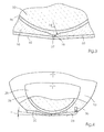
- In Fig. 3 ist eine Detailansicht eines zweiteiligen Düsenblechs 33 gezeigt. Hierbei wird die Auftragsdüsenöffnung 16 durch die Verschlusskante 37 des beweglichen Teils des zweiteiligen Düsenblechs 33 verschlossen. In Fig. 4 ist zudem ein Öffnungswinkel α gezeigt, der zwischen der Auftragsebene und dem zweiteiligen Düsenblech 33 vorgesehen ist. Durch diesen Öffnungswinkel α wird verhindert, dass der aufgetragene Klebstoff 2 auf dem Buchblock 1 nochmals in Kontakt mit dem Düsenblech 33 kommt, so dass die Qualität der Klebstoffspur 2 nicht verschlechtert wird. Außerdem ist in Fig. 4 ein Ziehkeil 36 gezeigt, der zur feinfühligen Ein- und Nachstellung der lichten Weite des Spaltes im zweiteiligen Düsenblech verwendet wird. Durch das zweiteilige Düsenblech 33 ist auf diese Weise eine Einflussnahme auf die gewünschte Schlitzweite möglich.
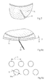
- In Fig. 5 und 6 ist eine weitere Ausführungsform der erfindungsgemäßen Auftragsvorrichtung 100 gezeigt, wobei mittels Schrauben 35 ein einteiliges Düsenblech 32 oberhalb der Auftragsdüsenöffnung 16 angebracht ist. Zudem ist ein Ventil 18 gezeigt, das den Klebstofffluss in die Klebstoffkammer 11 regelt. Wie in Fig. 7 gezeigt ist, weist das einteilige Düsenblech 32 in einer Ausführungsform einen Schlitz 38 auf, in einer in Fig. 8a gezeigten anderen Ausführungsform eine Doppelreihe 39, bestehend aus zueinander versetzten Löchern 39a mit Durchmesser D und Abstand A von Mittelpunkt zu Mittelpunkt innerhalb einer Reihe, wobei der Abstand A kleiner ist als zwei Abstände D, so dass über die gesamte Breite der Doppelreihe 39 Klebstoff 2 fließen kann. Diese Ausführungsform mit den Löchern 39a weist gegenüber einem durchgehenden Schlitz 38 eine höhere Stabilität auf. Vorteilhafterweise ist auch zwischen dem einteiligen Düsenblech 32 und der Auftragsebene ein Öffnungswinkel β vorgesehen, der verhindert, dass die Klebstoffspur 2 nach dem Auftrag auf dem Buchblock 1 noch in Kontakt mit dem Auftragskopf 10 kommt. Abweichend zu kreisrunden Löchern 39a sind auch andere Formen denkbar, etwa Dreiecke oder hexagonale Öffnungen. Das einteilige Düsenblech 32 kann auf einfache Art und Weise durch Lösen der Schrauben 35 von dem Auftragskopf 10 entfernt werden, um es zu reinigen oder auszuwechseln.
- Das erfindungsgemäße Auftragssystem 100 wurde besonders in Verbindung mit der Klebebindung von Buchblöcken 1 beschrieben, ist aber auch in anderen Applikationen verwendbar, bei denen eine definierte Klebstoffmenge in unterschiedlicher Breite auf eine Oberfläche aufgebracht werden muss, etwa bei der Holzverarbeitung.
-
- 1
- Buchblock
- 2
- Klebstoff / Klebstoffspur
- 10
- Auftragskopf
- 11
- Klebstoffkammer
- 12
- Klebstoffeinlassöffnung
- 14
- Schwächung
- 16
- Auftragsdüsenöffnung
- 18
- Ventil
- 20
- Dosierwalze
- 22
- Vertiefung auf der Dosierwalze
- 23
- Seitenbereich
- 25
- Drehrichtung der Dosierwalze
- 26,a,b
- Dichtungsring
- 28
- Antrieb
- 30
- Verstellmittel
- 32
- einteiliges Düsenblech
- 33
- zweiteiliges Düsenblech
- 34
- Düsenblechöffnung
- 35
- Schraube
- 36
- Ziehkeil
- 37
- Verschlusskante des zweiteiligen Düsenblechs
- 38
- Schlitz
- 39
- Doppelreihe
- 39a
- Loch
- 40
- Heizelement
- 50
- Steuerung
- 100
- Auftragsvorrichtung
- A
- Abstand der Löchermittelpunkte
- R
- Radius der Löcher
- α
- Öffnungswinkel zwischen Düsenblech und Buchblock
- β
- Öffnungswinkel zwischen Düsenblech und Buchblock Patentansprüche
Claims (12)
- Auftragssystem (100) für Klebstoff (2) mit einer zylindrischen Klebstoffkammer (11), wobei innerhalb der zylindrischen Klebstoffkammer (11) eine zylindrische Dosierwalze (20) angeordnet ist, wobei die zylindrische Dosierwalze (20) am Umfang eine Vertiefung (22) aufweist, die in axialer Richtung unterschiedliche Länge aufweist, etwa in Form eines Trapezes, einer Raute, eines Ovals, eines Dreiecks oder anderer Formen, wobei die Vertiefung (22) der zylindrischen Dosierwalze (20) mit einer Auftragsdüsenöffnung (16) des Auftragssystems wechselwirkt, wobei durch die Länge der Vertiefung (22) in axialer Richtung die gegenüber der Auftragsdüsenöffnung (16) liegt, die Klebstoffauftragsbreite der Auftragsdüsenöffnung (16) im Wesentlichen vorgegeben ist,
dadurch gekennzeichnet, dass
das Auftragssystem (100) Verschlussmittel (30, 32, 33, 34, 36, 37) für die Auftragsdüsenöffnung (16) umfasst. - Auftragssystem (100) für Klebstoff gemäß Anspruch 1,
dadurch gekennzeichnet, dass
es sich bei dem Verschlussmittel (30, 32, 33, 34, 36, 37) der Auftragsdüsenöffnung (16) um ein zweigeteiltes Düsenblech (33) handelt, dass wenigstens eine Verschlusskante (37) aufweist, wobei die Verschlusskante (37) relativ zu der Auftragsdüsenöffnung (16) verschiebbar angeordnet ist, derart, dass durch eine Überdeckung der Verschlusskante (37) und der Auftragsdüsenöffnung (16) der Klebstofffluss verhinderbar ist. - Auftragssystem (100) für Klebstoff gemäß Anspruch 1,
dadurch gekennzeichnet, dass
es sich bei dem Verschlussmittel (30, 32, 33, 34, 36, 37) der Auftragsdüsenöffnung (16) um ein Düsenblech (32) handelt, dass wenigstens eine Düsenblechöffnung (34) aufweist, wobei die Düsenblechöffnung (34) relativ zu der Auftragsdüsenöffnung (16) verschiebbar angeordnet ist, derart, dass nur bei einer wenigstens teilweisen Überdeckung der Düsenblechöffnung (34) und der Auftragsdüsenöffnung (16) Klebstoff (2) strömen kann. - Auftragssystem (100) für Klebstoff gemäß Anspruch 3,
dadurch gekennzeichnet, dass
das Düsenblech (32) eine Doppelreihe (39) versetzt zueinander angeordneter Löcher (39a) aufweist, durch die der Klebstoff (2) je nach Auftragsbreite beim Auftragen strömt. - Auftragssystem (100) für Klebstoff gemäß Anspruch 1,
dadurch gekennzeichnet, dass
die Verschlussmittel (30, 32, 33, 34, 36, 37) der Auftragsdüsenöffnung (16) ein Verstellmittel (30, 36) aufweisen, vermittels der die Relativbewegung zwischen Auftragsdüsenöffnung (16) und Düsenblechöffnung erzeugbar ist. - Auftragssystem (100) für Klebstoff gemäß Anspruch 1,
dadurch gekennzeichnet, dass
auf der Dosierwalze (20) entlang der Vertiefung (22) ein mit der zylindrischen Klebstoffkammer (11) abschließende Dichtung (26a) angeordnet ist - Auftragssystem (100) für Klebstoff gemäß Anspruch 1,
dadurch gekennzeichnet, dass
in dem Seitenbereich (23) zwischen der zylindrischen Klebstoffkammer (11) und der Dosierwalze (20) außerhalb der Vertiefung (22) ein Gleitfett aufgetragen ist, welches bei der Temperatur des heißen Klebstoffs hochviskose Eigenschaften hat. - Auftragssystem (100) für Klebstoff gemäß Anspruch 1,
dadurch gekennzeichnet, dass
die Dosierwalze (20) und die zylindrischen Klebstoffkammer (11) mit haftungsverringernden Materialien bedeckt oder aus Materialien mit niedriger Haftung aufgebaut sind, etwa PTFE. - Auftragssystem (100) für Klebstoff gemäß Anspruch 1,
dadurch gekennzeichnet, dass
das Auftragssystem (100) eine Steuerung (50) umfasst, zum automatischen Öffnen und Verschließen der Auftragsdüsenöffnung (16) durch die Verschlussmittel (30, 32, 33, 34, 36, 37) der Auftragsdüsenöffnung (16). - Auftragssystem (100) für Klebstoff gemäß Anspruch 1,
dadurch gekennzeichnet, dass
das Auftragssystem (100) eine Steuerung (50) umfasst, wobei mittels der Steuerung (50) und einem Antrieb (28) der Dosierwalze (20) automatisch die Klebstoffauftragsbreite der Auftragsdüsenöffnung (16) durch Rotation der Dosierwalze (20) einstellbar ist. - Auftragssystem (100) für Klebstoff gemäß Anspruch 1,
dadurch gekennzeichnet, dass
das Auftragssystem (100) eine Heizung (40) umfasst. - Auftragssystem (100) für Klebstoff gemäß Anspruch 1,
dadurch gekennzeichnet, dass
es sich bei dem Klebstoff (77) um einen reaktiven Heißklebstoff handelt, insbesondere um Polyurethan.
Applications Claiming Priority (1)
| Application Number | Priority Date | Filing Date | Title |
|---|---|---|---|
| DE200510044273 DE102005044273A1 (de) | 2005-09-16 | 2005-09-16 | Düsenauftragssystem für Klebstoff |
Publications (2)
| Publication Number | Publication Date |
|---|---|
| EP1764231A2 true EP1764231A2 (de) | 2007-03-21 |
| EP1764231A3 EP1764231A3 (de) | 2012-08-29 |
Family
ID=37507610
Family Applications (1)
| Application Number | Title | Priority Date | Filing Date |
|---|---|---|---|
| EP06120570A Withdrawn EP1764231A3 (de) | 2005-09-16 | 2006-09-13 | Düsenauftragssystem für Klebstoff |
Country Status (2)
| Country | Link |
|---|---|
| EP (1) | EP1764231A3 (de) |
| DE (1) | DE102005044273A1 (de) |
Cited By (2)
| Publication number | Priority date | Publication date | Assignee | Title |
|---|---|---|---|---|
| WO2011117676A1 (en) * | 2010-03-24 | 2011-09-29 | New Bind Srl | Glue applicator for bookbinding machines |
| WO2017209926A1 (en) | 2016-05-31 | 2017-12-07 | 3M Innovative Properties Company | Cam die coating systems |
Family Cites Families (9)
| Publication number | Priority date | Publication date | Assignee | Title |
|---|---|---|---|---|
| CH648497A5 (en) * | 1982-09-24 | 1985-03-29 | Billeter Kunststoffpulver Ag | Device for surface coating, directly or according to the transfer printing principle, a substrate |
| US4667879A (en) * | 1985-08-21 | 1987-05-26 | Nordson Corporation | Thermoplastic material applicator having an adjustable slot nozzle |
| JPS6268569A (ja) * | 1985-09-20 | 1987-03-28 | Meiji Kikai Seisakusho:Kk | 接着剤塗付具 |
| DE3804856A1 (de) * | 1988-02-17 | 1989-08-31 | Macon Gmbh Klebstoff Auftragsg | Vorrichtung zum flaechigen auftragen von leim oder dergleichen |
| US5271794A (en) * | 1992-01-09 | 1993-12-21 | Nordson Corporation | Adjustable width coating nozzle and side sealer |
| JP2917127B2 (ja) * | 1996-07-12 | 1999-07-12 | 井上金属工業株式会社 | 塗布装置 |
| EP1042074B1 (de) * | 1997-12-22 | 2003-04-02 | Wolfgang Puffe | Rotationsauftragskopf |
| EP1033262A1 (de) * | 1999-03-01 | 2000-09-06 | Sogno AG | Kleberauftragsstation für Druckerzeugnisse |
| DE10210748B4 (de) * | 2002-03-12 | 2015-06-18 | Nordson Corp. | Rotationsauftragskopf |
-
2005
- 2005-09-16 DE DE200510044273 patent/DE102005044273A1/de not_active Withdrawn
-
2006
- 2006-09-13 EP EP06120570A patent/EP1764231A3/de not_active Withdrawn
Cited By (5)
| Publication number | Priority date | Publication date | Assignee | Title |
|---|---|---|---|---|
| WO2011117676A1 (en) * | 2010-03-24 | 2011-09-29 | New Bind Srl | Glue applicator for bookbinding machines |
| CN102933399A (zh) * | 2010-03-24 | 2013-02-13 | 4B-四邦有限责任公司 | 用于装订机的涂胶器 |
| WO2017209926A1 (en) | 2016-05-31 | 2017-12-07 | 3M Innovative Properties Company | Cam die coating systems |
| EP3463684A4 (de) * | 2016-05-31 | 2020-01-22 | 3M Innovative Properties Company | Nockendüsenbeschichtungssysteme |
| US10882068B2 (en) | 2016-05-31 | 2021-01-05 | 3M Innovative Properties Company | Cam die coating systems |
Also Published As
| Publication number | Publication date |
|---|---|
| EP1764231A3 (de) | 2012-08-29 |
| DE102005044273A1 (de) | 2007-03-29 |
Similar Documents
| Publication | Publication Date | Title |
|---|---|---|
| DE69215223T2 (de) | Düsen | |
| DE1696650C3 (de) | Verfahren und Vorrichtung zum Beschichten von bandförmigem Material mit einer erhitzten thermoplastischen Substanz | |
| DE3438380A1 (de) | Streicheinrichtung zur beschichtung laufender warenbahnen | |
| EP0850697A2 (de) | Vorrichtung zum Auftragen von fliessfähigem Material auf ein Substrat, insbesondere zum intermittierenden Auftragen von flüssigem Klebstoff | |
| DE102018120445B3 (de) | Filtriervorrichtung für hochviskose Medien | |
| EP0158220A2 (de) | Mittels eines Wärme übertragenden Mediums beheizbare Kalanderwalze | |
| DE3931793A1 (de) | Ein geraet zur beschichtung einer fahrenden bahn | |
| DE3513063C2 (de) | ||
| DE2555669A1 (de) | Vorrichtung zum abstreifen ueberschuessiger streichmasse | |
| DE19722117C2 (de) | Beschichtung poröser Träger | |
| DE2935677C2 (de) | Vorrichtung zur Herstellung von einseitiger Wellpappe | |
| DE3530508C2 (de) | ||
| DE2350375B2 (de) | Misch- oder verteilventil | |
| EP0744220B1 (de) | Schlitzdüse | |
| EP0266639B1 (de) | Vorrichtung zur Durchflusssteuerung | |
| DE2359413C3 (de) | Vorrichtung zum Beschichten laufender Werkstoffbahnen aus Papier, Karton, Kunststoff o.dgl. | |
| DD231280A5 (de) | Streichkopf | |
| DE102005044273A1 (de) | Düsenauftragssystem für Klebstoff | |
| DE8812493U1 (de) | Schlitzdüse | |
| EP0166955B1 (de) | Farbkasten für Rotationsdruckmaschinen mit einer Farbdosiereinrichtung | |
| DE69611520T2 (de) | Umlaufender regenerativer wärmetauscher und verfahren zum betreiben eines umlaufenden regenerativen wärmetauschers | |
| EP0056067B1 (de) | Vorrichtung zum Aufbringen einer dünnen Schicht eines Beschichtungsmaterials auf eine laufende Materialbahn | |
| DE202006019724U1 (de) | Vorrichtung mit Schlitzdüsenanordnung zum Abgeben von Fluid | |
| DE10131825C1 (de) | Farbmesseranordnung an einem Farbkasten einer Druckmaschine | |
| DE3308066C1 (de) | Farbdosiervorrichtung fuer eine Farbkastenwalze |
Legal Events
| Date | Code | Title | Description |
|---|---|---|---|
| PUAI | Public reference made under article 153(3) epc to a published international application that has entered the european phase |
Free format text: ORIGINAL CODE: 0009012 |
|
| AK | Designated contracting states |
Kind code of ref document: A2 Designated state(s): AT BE BG CH CY CZ DE DK EE ES FI FR GB GR HU IE IS IT LI LT LU LV MC NL PL PT RO SE SI SK TR |
|
| AX | Request for extension of the european patent |
Extension state: AL BA HR MK YU |
|
| PUAL | Search report despatched |
Free format text: ORIGINAL CODE: 0009013 |
|
| AK | Designated contracting states |
Kind code of ref document: A3 Designated state(s): AT BE BG CH CY CZ DE DK EE ES FI FR GB GR HU IE IS IT LI LT LU LV MC NL PL PT RO SE SI SK TR |
|
| AX | Request for extension of the european patent |
Extension state: AL BA HR MK RS |
|
| RIC1 | Information provided on ipc code assigned before grant |
Ipc: B05C 1/10 20060101ALI20120723BHEP Ipc: B42C 9/00 20060101AFI20120723BHEP |
|
| AKY | No designation fees paid | ||
| REG | Reference to a national code |
Ref country code: DE Ref legal event code: R108 |
|
| REG | Reference to a national code |
Ref country code: DE Ref legal event code: R108 Effective date: 20130508 |
|
| STAA | Information on the status of an ep patent application or granted ep patent |
Free format text: STATUS: THE APPLICATION IS DEEMED TO BE WITHDRAWN |
|
| 18D | Application deemed to be withdrawn |
Effective date: 20130301 |