EP1763099A2 - Stabile Elektrolyt-Gegenanionen für elektrochemische Vorrichtungen - Google Patents
Stabile Elektrolyt-Gegenanionen für elektrochemische Vorrichtungen Download PDFInfo
- Publication number
- EP1763099A2 EP1763099A2 EP06017458A EP06017458A EP1763099A2 EP 1763099 A2 EP1763099 A2 EP 1763099A2 EP 06017458 A EP06017458 A EP 06017458A EP 06017458 A EP06017458 A EP 06017458A EP 1763099 A2 EP1763099 A2 EP 1763099A2
- Authority
- EP
- European Patent Office
- Prior art keywords
- electrolyte
- lithium
- acid
- salt
- polymer
- Prior art date
- Legal status (The legal status is an assumption and is not a legal conclusion. Google has not performed a legal analysis and makes no representation as to the accuracy of the status listed.)
- Granted
Links
- 239000003792 electrolyte Substances 0.000 title claims abstract description 113
- 150000003839 salts Chemical class 0.000 claims abstract description 109
- 229920000642 polymer Polymers 0.000 claims abstract description 61
- 229910052739 hydrogen Inorganic materials 0.000 claims abstract description 49
- 150000001450 anions Chemical class 0.000 claims abstract description 43
- 125000000217 alkyl group Chemical group 0.000 claims abstract description 31
- 239000001257 hydrogen Substances 0.000 claims abstract description 31
- 229910052794 bromium Inorganic materials 0.000 claims abstract description 21
- 229910052801 chlorine Inorganic materials 0.000 claims abstract description 21
- 125000003118 aryl group Chemical group 0.000 claims abstract description 10
- 125000005010 perfluoroalkyl group Chemical group 0.000 claims abstract description 9
- 125000000753 cycloalkyl group Chemical group 0.000 claims abstract description 8
- 125000003709 fluoroalkyl group Chemical group 0.000 claims abstract description 7
- 229910015488 B12Fx Inorganic materials 0.000 claims abstract description 6
- XLYOFNOQVPJJNP-UHFFFAOYSA-N water Substances O XLYOFNOQVPJJNP-UHFFFAOYSA-N 0.000 claims description 106
- 239000002253 acid Substances 0.000 claims description 98
- 239000003990 capacitor Substances 0.000 claims description 73
- 239000000203 mixture Substances 0.000 claims description 69
- 239000000446 fuel Substances 0.000 claims description 50
- 239000002904 solvent Substances 0.000 claims description 31
- 229910052760 oxygen Inorganic materials 0.000 claims description 24
- QVGXLLKOCUKJST-UHFFFAOYSA-N atomic oxygen Chemical compound [O] QVGXLLKOCUKJST-UHFFFAOYSA-N 0.000 claims description 23
- 239000001301 oxygen Substances 0.000 claims description 23
- 150000007513 acids Chemical class 0.000 claims description 22
- 238000000034 method Methods 0.000 claims description 22
- UFHFLCQGNIYNRP-UHFFFAOYSA-N Hydrogen Chemical compound [H][H] UFHFLCQGNIYNRP-UHFFFAOYSA-N 0.000 claims description 19
- 230000008569 process Effects 0.000 claims description 14
- 150000002431 hydrogen Chemical class 0.000 claims description 11
- 125000004793 2,2,2-trifluoroethoxy group Chemical group FC(CO*)(F)F 0.000 claims description 2
- 239000000126 substance Substances 0.000 abstract description 10
- 230000006872 improvement Effects 0.000 abstract description 5
- 125000004435 hydrogen atom Chemical class [H]* 0.000 abstract 2
- -1 aluminum cations Chemical class 0.000 description 64
- 239000000243 solution Substances 0.000 description 60
- 229910052744 lithium Inorganic materials 0.000 description 58
- WHXSMMKQMYFTQS-UHFFFAOYSA-N Lithium Chemical compound [Li] WHXSMMKQMYFTQS-UHFFFAOYSA-N 0.000 description 57
- NBIIXXVUZAFLBC-UHFFFAOYSA-N Phosphoric acid Chemical compound OP(O)(O)=O NBIIXXVUZAFLBC-UHFFFAOYSA-N 0.000 description 56
- 238000012360 testing method Methods 0.000 description 52
- 150000001768 cations Chemical class 0.000 description 41
- 239000004020 conductor Substances 0.000 description 36
- 239000012528 membrane Substances 0.000 description 34
- 239000007787 solid Substances 0.000 description 34
- ZMANZCXQSJIPKH-UHFFFAOYSA-N Triethylamine Chemical compound CCN(CC)CC ZMANZCXQSJIPKH-UHFFFAOYSA-N 0.000 description 33
- BASFCYQUMIYNBI-UHFFFAOYSA-N platinum Chemical compound [Pt] BASFCYQUMIYNBI-UHFFFAOYSA-N 0.000 description 30
- 238000003682 fluorination reaction Methods 0.000 description 28
- 229910001416 lithium ion Inorganic materials 0.000 description 27
- 239000007788 liquid Substances 0.000 description 26
- IEJIGPNLZYLLBP-UHFFFAOYSA-N dimethyl carbonate Chemical compound COC(=O)OC IEJIGPNLZYLLBP-UHFFFAOYSA-N 0.000 description 24
- 239000011777 magnesium Substances 0.000 description 23
- 230000009467 reduction Effects 0.000 description 23
- OKKJLVBELUTLKV-UHFFFAOYSA-N Methanol Chemical compound OC OKKJLVBELUTLKV-UHFFFAOYSA-N 0.000 description 22
- 229910000147 aluminium phosphate Inorganic materials 0.000 description 20
- 229910052749 magnesium Inorganic materials 0.000 description 20
- KMTRUDSVKNLOMY-UHFFFAOYSA-N Ethylene carbonate Chemical compound O=C1OCCO1 KMTRUDSVKNLOMY-UHFFFAOYSA-N 0.000 description 18
- FYYHWMGAXLPEAU-UHFFFAOYSA-N Magnesium Chemical compound [Mg] FYYHWMGAXLPEAU-UHFFFAOYSA-N 0.000 description 18
- 239000007864 aqueous solution Substances 0.000 description 18
- 239000000460 chlorine Substances 0.000 description 18
- 238000002484 cyclic voltammetry Methods 0.000 description 18
- 125000000956 methoxy group Chemical group [H]C([H])([H])O* 0.000 description 18
- HBBGRARXTFLTSG-UHFFFAOYSA-N Lithium ion Chemical compound [Li+] HBBGRARXTFLTSG-UHFFFAOYSA-N 0.000 description 17
- 229910052799 carbon Inorganic materials 0.000 description 17
- 230000003647 oxidation Effects 0.000 description 17
- 238000007254 oxidation reaction Methods 0.000 description 17
- 239000000047 product Substances 0.000 description 17
- OKTJSMMVPCPJKN-UHFFFAOYSA-N Carbon Chemical compound [C] OKTJSMMVPCPJKN-UHFFFAOYSA-N 0.000 description 16
- 238000006243 chemical reaction Methods 0.000 description 16
- 238000002360 preparation method Methods 0.000 description 16
- 238000007600 charging Methods 0.000 description 15
- 229940021013 electrolyte solution Drugs 0.000 description 15
- 230000006870 function Effects 0.000 description 15
- 150000002500 ions Chemical class 0.000 description 15
- 239000011734 sodium Substances 0.000 description 15
- 239000008151 electrolyte solution Substances 0.000 description 14
- 238000005259 measurement Methods 0.000 description 14
- BDAGIHXWWSANSR-UHFFFAOYSA-N methanoic acid Natural products OC=O BDAGIHXWWSANSR-UHFFFAOYSA-N 0.000 description 14
- IJGRMHOSHXDMSA-UHFFFAOYSA-N nitrogen Substances N#N IJGRMHOSHXDMSA-UHFFFAOYSA-N 0.000 description 14
- WEVYAHXRMPXWCK-UHFFFAOYSA-N Acetonitrile Chemical compound CC#N WEVYAHXRMPXWCK-UHFFFAOYSA-N 0.000 description 12
- QAOWNCQODCNURD-UHFFFAOYSA-N Sulfuric acid Chemical compound OS(O)(=O)=O QAOWNCQODCNURD-UHFFFAOYSA-N 0.000 description 12
- RHQDFWAXVIIEBN-UHFFFAOYSA-N Trifluoroethanol Chemical compound OCC(F)(F)F RHQDFWAXVIIEBN-UHFFFAOYSA-N 0.000 description 12
- 239000011575 calcium Substances 0.000 description 12
- 230000001351 cycling effect Effects 0.000 description 12
- 229910052782 aluminium Inorganic materials 0.000 description 11
- XAGFODPZIPBFFR-UHFFFAOYSA-N aluminium Chemical compound [Al] XAGFODPZIPBFFR-UHFFFAOYSA-N 0.000 description 11
- 238000004146 energy storage Methods 0.000 description 11
- 239000003365 glass fiber Substances 0.000 description 11
- RUOJZAUFBMNUDX-UHFFFAOYSA-N propylene carbonate Chemical compound CC1COC(=O)O1 RUOJZAUFBMNUDX-UHFFFAOYSA-N 0.000 description 11
- 229910052791 calcium Inorganic materials 0.000 description 10
- 239000002131 composite material Substances 0.000 description 10
- 239000012535 impurity Substances 0.000 description 10
- 238000002411 thermogravimetry Methods 0.000 description 10
- ZOXJGFHDIHLPTG-UHFFFAOYSA-N Boron Chemical group [B] ZOXJGFHDIHLPTG-UHFFFAOYSA-N 0.000 description 9
- OYPRJOBELJOOCE-UHFFFAOYSA-N Calcium Chemical compound [Ca] OYPRJOBELJOOCE-UHFFFAOYSA-N 0.000 description 9
- 230000008901 benefit Effects 0.000 description 9
- 229910052731 fluorine Inorganic materials 0.000 description 9
- 229920001296 polysiloxane Polymers 0.000 description 9
- 239000002002 slurry Substances 0.000 description 9
- 239000011973 solid acid Substances 0.000 description 9
- CSCPPACGZOOCGX-UHFFFAOYSA-N Acetone Chemical compound CC(C)=O CSCPPACGZOOCGX-UHFFFAOYSA-N 0.000 description 8
- YCKRFDGAMUMZLT-UHFFFAOYSA-N Fluorine atom Chemical compound [F] YCKRFDGAMUMZLT-UHFFFAOYSA-N 0.000 description 8
- PXHVJJICTQNCMI-UHFFFAOYSA-N Nickel Chemical compound [Ni] PXHVJJICTQNCMI-UHFFFAOYSA-N 0.000 description 8
- DOIRQSBPFJWKBE-UHFFFAOYSA-N dibutyl phthalate Chemical compound CCCCOC(=O)C1=CC=CC=C1C(=O)OCCCC DOIRQSBPFJWKBE-UHFFFAOYSA-N 0.000 description 8
- 239000010408 film Substances 0.000 description 8
- 239000011737 fluorine Substances 0.000 description 8
- 229910052757 nitrogen Inorganic materials 0.000 description 8
- 239000003960 organic solvent Substances 0.000 description 8
- 230000002441 reversible effect Effects 0.000 description 8
- 238000012546 transfer Methods 0.000 description 8
- 238000004293 19F NMR spectroscopy Methods 0.000 description 7
- OSWFIVFLDKOXQC-UHFFFAOYSA-N 4-(3-methoxyphenyl)aniline Chemical compound COC1=CC=CC(C=2C=CC(N)=CC=2)=C1 OSWFIVFLDKOXQC-UHFFFAOYSA-N 0.000 description 7
- WMFOQBRAJBCJND-UHFFFAOYSA-M Lithium hydroxide Chemical compound [Li+].[OH-] WMFOQBRAJBCJND-UHFFFAOYSA-M 0.000 description 7
- 230000015572 biosynthetic process Effects 0.000 description 7
- 229910052796 boron Inorganic materials 0.000 description 7
- 235000019253 formic acid Nutrition 0.000 description 7
- 239000000463 material Substances 0.000 description 7
- 230000001590 oxidative effect Effects 0.000 description 7
- 229920000570 polyether Polymers 0.000 description 7
- 239000004642 Polyimide Substances 0.000 description 6
- 238000004458 analytical method Methods 0.000 description 6
- 239000000010 aprotic solvent Substances 0.000 description 6
- 239000003054 catalyst Substances 0.000 description 6
- 230000036571 hydration Effects 0.000 description 6
- 238000006703 hydration reaction Methods 0.000 description 6
- RAXXELZNTBOGNW-UHFFFAOYSA-N imidazole Natural products C1=CNC=N1 RAXXELZNTBOGNW-UHFFFAOYSA-N 0.000 description 6
- 239000000155 melt Substances 0.000 description 6
- 229910052697 platinum Inorganic materials 0.000 description 6
- 229920001721 polyimide Polymers 0.000 description 6
- 230000002829 reductive effect Effects 0.000 description 6
- 238000003860 storage Methods 0.000 description 6
- QTBSBXVTEAMEQO-UHFFFAOYSA-N Acetic acid Chemical compound CC(O)=O QTBSBXVTEAMEQO-UHFFFAOYSA-N 0.000 description 5
- RTZKZFJDLAIYFH-UHFFFAOYSA-N Diethyl ether Chemical compound CCOCC RTZKZFJDLAIYFH-UHFFFAOYSA-N 0.000 description 5
- 239000004698 Polyethylene Substances 0.000 description 5
- 229910052783 alkali metal Inorganic materials 0.000 description 5
- WTEOIRVLGSZEPR-UHFFFAOYSA-N boron trifluoride Chemical compound FB(F)F WTEOIRVLGSZEPR-UHFFFAOYSA-N 0.000 description 5
- 150000001642 boronic acid derivatives Chemical class 0.000 description 5
- 230000008859 change Effects 0.000 description 5
- 150000001875 compounds Chemical class 0.000 description 5
- 229920001577 copolymer Polymers 0.000 description 5
- 239000012043 crude product Substances 0.000 description 5
- 238000011156 evaluation Methods 0.000 description 5
- XLYOFNOQVPJJNP-ZSJDYOACSA-N heavy water Substances [2H]O[2H] XLYOFNOQVPJJNP-ZSJDYOACSA-N 0.000 description 5
- 125000002887 hydroxy group Chemical group [H]O* 0.000 description 5
- 230000008018 melting Effects 0.000 description 5
- 238000002844 melting Methods 0.000 description 5
- 229910052751 metal Inorganic materials 0.000 description 5
- 239000002184 metal Substances 0.000 description 5
- 125000002496 methyl group Chemical group [H]C([H])([H])* 0.000 description 5
- 229920000573 polyethylene Polymers 0.000 description 5
- 239000002243 precursor Substances 0.000 description 5
- 238000010926 purge Methods 0.000 description 5
- 229920005989 resin Polymers 0.000 description 5
- 239000011347 resin Substances 0.000 description 5
- 238000000926 separation method Methods 0.000 description 5
- 238000001179 sorption measurement Methods 0.000 description 5
- 229910015900 BF3 Inorganic materials 0.000 description 4
- KAKZBPTYRLMSJV-UHFFFAOYSA-N Butadiene Chemical group C=CC=C KAKZBPTYRLMSJV-UHFFFAOYSA-N 0.000 description 4
- LYCAIKOWRPUZTN-UHFFFAOYSA-N Ethylene glycol Chemical compound OCCO LYCAIKOWRPUZTN-UHFFFAOYSA-N 0.000 description 4
- 229910010912 Li2B12F12 Inorganic materials 0.000 description 4
- 229920003171 Poly (ethylene oxide) Polymers 0.000 description 4
- 239000004721 Polyphenylene oxide Substances 0.000 description 4
- 239000000654 additive Substances 0.000 description 4
- TZCXTZWJZNENPQ-UHFFFAOYSA-L barium sulfate Chemical compound [Ba+2].[O-]S([O-])(=O)=O TZCXTZWJZNENPQ-UHFFFAOYSA-L 0.000 description 4
- 239000002585 base Substances 0.000 description 4
- 230000001143 conditioned effect Effects 0.000 description 4
- 229960002380 dibutyl phthalate Drugs 0.000 description 4
- 230000000694 effects Effects 0.000 description 4
- 238000001914 filtration Methods 0.000 description 4
- 229910052736 halogen Inorganic materials 0.000 description 4
- 125000005843 halogen group Chemical group 0.000 description 4
- 150000002367 halogens Chemical class 0.000 description 4
- 238000010438 heat treatment Methods 0.000 description 4
- AMXOYNBUYSYVKV-UHFFFAOYSA-M lithium bromide Chemical compound [Li+].[Br-] AMXOYNBUYSYVKV-UHFFFAOYSA-M 0.000 description 4
- MHCFAGZWMAWTNR-UHFFFAOYSA-M lithium perchlorate Chemical compound [Li+].[O-]Cl(=O)(=O)=O MHCFAGZWMAWTNR-UHFFFAOYSA-M 0.000 description 4
- 229910003002 lithium salt Inorganic materials 0.000 description 4
- 159000000002 lithium salts Chemical class 0.000 description 4
- VNWKTOKETHGBQD-UHFFFAOYSA-N methane Chemical compound C VNWKTOKETHGBQD-UHFFFAOYSA-N 0.000 description 4
- 239000011255 nonaqueous electrolyte Substances 0.000 description 4
- 229920002239 polyacrylonitrile Polymers 0.000 description 4
- 239000002516 radical scavenger Substances 0.000 description 4
- 238000003786 synthesis reaction Methods 0.000 description 4
- 229910015486 B12FxH12-x Inorganic materials 0.000 description 3
- 229910011120 Li2B12Fx Inorganic materials 0.000 description 3
- 229910001290 LiPF6 Inorganic materials 0.000 description 3
- JLVVSXFLKOJNIY-UHFFFAOYSA-N Magnesium ion Chemical compound [Mg+2] JLVVSXFLKOJNIY-UHFFFAOYSA-N 0.000 description 3
- ZMXDDKWLCZADIW-UHFFFAOYSA-N N,N-Dimethylformamide Chemical compound CN(C)C=O ZMXDDKWLCZADIW-UHFFFAOYSA-N 0.000 description 3
- SECXISVLQFMRJM-UHFFFAOYSA-N N-Methylpyrrolidone Chemical compound CN1CCCC1=O SECXISVLQFMRJM-UHFFFAOYSA-N 0.000 description 3
- 238000005481 NMR spectroscopy Methods 0.000 description 3
- HEMHJVSKTPXQMS-UHFFFAOYSA-M Sodium hydroxide Chemical compound [OH-].[Na+] HEMHJVSKTPXQMS-UHFFFAOYSA-M 0.000 description 3
- 238000010521 absorption reaction Methods 0.000 description 3
- 230000002378 acidificating effect Effects 0.000 description 3
- 239000003513 alkali Substances 0.000 description 3
- 150000001340 alkali metals Chemical class 0.000 description 3
- 150000001721 carbon Chemical group 0.000 description 3
- 229920001429 chelating resin Polymers 0.000 description 3
- 229910001914 chlorine tetroxide Inorganic materials 0.000 description 3
- XLJKHNWPARRRJB-UHFFFAOYSA-N cobalt(2+) Chemical compound [Co+2] XLJKHNWPARRRJB-UHFFFAOYSA-N 0.000 description 3
- 125000004122 cyclic group Chemical group 0.000 description 3
- 238000004821 distillation Methods 0.000 description 3
- 230000005611 electricity Effects 0.000 description 3
- 238000000157 electrochemical-induced impedance spectroscopy Methods 0.000 description 3
- 239000000706 filtrate Substances 0.000 description 3
- 229910021397 glassy carbon Inorganic materials 0.000 description 3
- 230000000670 limiting effect Effects 0.000 description 3
- 239000007791 liquid phase Substances 0.000 description 3
- 229910001486 lithium perchlorate Inorganic materials 0.000 description 3
- 229910001496 lithium tetrafluoroborate Inorganic materials 0.000 description 3
- MCVFFRWZNYZUIJ-UHFFFAOYSA-M lithium;trifluoromethanesulfonate Chemical compound [Li+].[O-]S(=O)(=O)C(F)(F)F MCVFFRWZNYZUIJ-UHFFFAOYSA-M 0.000 description 3
- 229910001425 magnesium ion Inorganic materials 0.000 description 3
- 230000014759 maintenance of location Effects 0.000 description 3
- 230000007935 neutral effect Effects 0.000 description 3
- 229910052759 nickel Inorganic materials 0.000 description 3
- 239000005486 organic electrolyte Substances 0.000 description 3
- VLTRZXGMWDSKGL-UHFFFAOYSA-M perchlorate Chemical compound [O-]Cl(=O)(=O)=O VLTRZXGMWDSKGL-UHFFFAOYSA-M 0.000 description 3
- 239000012071 phase Substances 0.000 description 3
- 229920002627 poly(phosphazenes) Polymers 0.000 description 3
- 229920002492 poly(sulfone) Polymers 0.000 description 3
- 229920001223 polyethylene glycol Polymers 0.000 description 3
- 229920001343 polytetrafluoroethylene Polymers 0.000 description 3
- 239000004810 polytetrafluoroethylene Substances 0.000 description 3
- 239000002244 precipitate Substances 0.000 description 3
- 239000012078 proton-conducting electrolyte Substances 0.000 description 3
- 238000006479 redox reaction Methods 0.000 description 3
- 239000008247 solid mixture Substances 0.000 description 3
- 239000011877 solvent mixture Substances 0.000 description 3
- 229910001220 stainless steel Inorganic materials 0.000 description 3
- 239000010935 stainless steel Substances 0.000 description 3
- 238000003756 stirring Methods 0.000 description 3
- 125000001424 substituent group Chemical group 0.000 description 3
- 125000005207 tetraalkylammonium group Chemical group 0.000 description 3
- ILWRPSCZWQJDMK-UHFFFAOYSA-N triethylazanium;chloride Chemical compound Cl.CCN(CC)CC ILWRPSCZWQJDMK-UHFFFAOYSA-N 0.000 description 3
- 238000001075 voltammogram Methods 0.000 description 3
- 230000004580 weight loss Effects 0.000 description 3
- 238000004607 11B NMR spectroscopy Methods 0.000 description 2
- OZJPLYNZGCXSJM-UHFFFAOYSA-N 5-valerolactone Chemical compound O=C1CCCCO1 OZJPLYNZGCXSJM-UHFFFAOYSA-N 0.000 description 2
- PAYRUJLWNCNPSJ-UHFFFAOYSA-N Aniline Chemical class NC1=CC=CC=C1 PAYRUJLWNCNPSJ-UHFFFAOYSA-N 0.000 description 2
- 229910015444 B(OH)3 Inorganic materials 0.000 description 2
- CURLTUGMZLYLDI-UHFFFAOYSA-N Carbon dioxide Chemical compound O=C=O CURLTUGMZLYLDI-UHFFFAOYSA-N 0.000 description 2
- OIFBSDVPJOWBCH-UHFFFAOYSA-N Diethyl carbonate Chemical compound CCOC(=O)OCC OIFBSDVPJOWBCH-UHFFFAOYSA-N 0.000 description 2
- XTHFKEDIFFGKHM-UHFFFAOYSA-N Dimethoxyethane Chemical compound COCCOC XTHFKEDIFFGKHM-UHFFFAOYSA-N 0.000 description 2
- LCGLNKUTAGEVQW-UHFFFAOYSA-N Dimethyl ether Chemical compound COC LCGLNKUTAGEVQW-UHFFFAOYSA-N 0.000 description 2
- IAZDPXIOMUYVGZ-UHFFFAOYSA-N Dimethylsulphoxide Chemical compound CS(C)=O IAZDPXIOMUYVGZ-UHFFFAOYSA-N 0.000 description 2
- KRHYYFGTRYWZRS-UHFFFAOYSA-N Fluorane Chemical compound F KRHYYFGTRYWZRS-UHFFFAOYSA-N 0.000 description 2
- MHAJPDPJQMAIIY-UHFFFAOYSA-N Hydrogen peroxide Chemical compound OO MHAJPDPJQMAIIY-UHFFFAOYSA-N 0.000 description 2
- SIKJAQJRHWYJAI-UHFFFAOYSA-N Indole Chemical compound C1=CC=C2NC=CC2=C1 SIKJAQJRHWYJAI-UHFFFAOYSA-N 0.000 description 2
- XEEYBQQBJWHFJM-UHFFFAOYSA-N Iron Chemical compound [Fe] XEEYBQQBJWHFJM-UHFFFAOYSA-N 0.000 description 2
- 229910011117 Li2B12FxH12-x Inorganic materials 0.000 description 2
- 229910002097 Lithium manganese(III,IV) oxide Inorganic materials 0.000 description 2
- VVQNEPGJFQJSBK-UHFFFAOYSA-N Methyl methacrylate Chemical class COC(=O)C(C)=C VVQNEPGJFQJSBK-UHFFFAOYSA-N 0.000 description 2
- 229910019389 Mg(CF3SO3)2 Inorganic materials 0.000 description 2
- YNAVUWVOSKDBBP-UHFFFAOYSA-N Morpholine Chemical compound C1COCCN1 YNAVUWVOSKDBBP-UHFFFAOYSA-N 0.000 description 2
- 229920000557 Nafion® Polymers 0.000 description 2
- NQRYJNQNLNOLGT-UHFFFAOYSA-N Piperidine Chemical compound C1CCNCC1 NQRYJNQNLNOLGT-UHFFFAOYSA-N 0.000 description 2
- JUJWROOIHBZHMG-UHFFFAOYSA-N Pyridine Chemical compound C1=CC=NC=C1 JUJWROOIHBZHMG-UHFFFAOYSA-N 0.000 description 2
- KAESVJOAVNADME-UHFFFAOYSA-N Pyrrole Chemical compound C=1C=CNC=1 KAESVJOAVNADME-UHFFFAOYSA-N 0.000 description 2
- SMWDFEZZVXVKRB-UHFFFAOYSA-N Quinoline Chemical compound N1=CC=CC2=CC=CC=C21 SMWDFEZZVXVKRB-UHFFFAOYSA-N 0.000 description 2
- PPBRXRYQALVLMV-UHFFFAOYSA-N Styrene Chemical compound C=CC1=CC=CC=C1 PPBRXRYQALVLMV-UHFFFAOYSA-N 0.000 description 2
- 229920006362 Teflon® Polymers 0.000 description 2
- DTQVDTLACAAQTR-UHFFFAOYSA-N Trifluoroacetic acid Chemical compound OC(=O)C(F)(F)F DTQVDTLACAAQTR-UHFFFAOYSA-N 0.000 description 2
- 229960000583 acetic acid Drugs 0.000 description 2
- 230000000996 additive effect Effects 0.000 description 2
- 150000008044 alkali metal hydroxides Chemical class 0.000 description 2
- AZDRQVAHHNSJOQ-UHFFFAOYSA-N alumane Chemical class [AlH3] AZDRQVAHHNSJOQ-UHFFFAOYSA-N 0.000 description 2
- PNEYBMLMFCGWSK-UHFFFAOYSA-N aluminium oxide Inorganic materials [O-2].[O-2].[O-2].[Al+3].[Al+3] PNEYBMLMFCGWSK-UHFFFAOYSA-N 0.000 description 2
- 239000011260 aqueous acid Substances 0.000 description 2
- 239000003125 aqueous solvent Substances 0.000 description 2
- 229910052785 arsenic Inorganic materials 0.000 description 2
- 125000004429 atom Chemical group 0.000 description 2
- 239000011230 binding agent Substances 0.000 description 2
- 238000009835 boiling Methods 0.000 description 2
- KGBXLFKZBHKPEV-UHFFFAOYSA-N boric acid Chemical compound OB(O)O KGBXLFKZBHKPEV-UHFFFAOYSA-N 0.000 description 2
- GDTBXPJZTBHREO-UHFFFAOYSA-N bromine Substances BrBr GDTBXPJZTBHREO-UHFFFAOYSA-N 0.000 description 2
- 230000005587 bubbling Effects 0.000 description 2
- 239000006227 byproduct Substances 0.000 description 2
- 159000000007 calcium salts Chemical class 0.000 description 2
- 150000004657 carbamic acid derivatives Chemical class 0.000 description 2
- 229960004424 carbon dioxide Drugs 0.000 description 2
- 235000011089 carbon dioxide Nutrition 0.000 description 2
- 230000015556 catabolic process Effects 0.000 description 2
- 239000000919 ceramic Substances 0.000 description 2
- MEAHOQPOZNHISZ-UHFFFAOYSA-M cesium;hydrogen sulfate Chemical compound [Cs+].OS([O-])(=O)=O MEAHOQPOZNHISZ-UHFFFAOYSA-M 0.000 description 2
- 239000007795 chemical reaction product Substances 0.000 description 2
- 229910017052 cobalt Inorganic materials 0.000 description 2
- 239000010941 cobalt Substances 0.000 description 2
- GUTLYIVDDKVIGB-UHFFFAOYSA-N cobalt atom Chemical compound [Co] GUTLYIVDDKVIGB-UHFFFAOYSA-N 0.000 description 2
- 239000002322 conducting polymer Substances 0.000 description 2
- 229920001940 conductive polymer Polymers 0.000 description 2
- 230000007797 corrosion Effects 0.000 description 2
- 238000005260 corrosion Methods 0.000 description 2
- 238000000354 decomposition reaction Methods 0.000 description 2
- 238000007599 discharging Methods 0.000 description 2
- 238000009826 distribution Methods 0.000 description 2
- 238000001035 drying Methods 0.000 description 2
- 229920001971 elastomer Polymers 0.000 description 2
- UQSQSQZYBQSBJZ-UHFFFAOYSA-N fluorosulfonic acid Chemical compound OS(F)(=O)=O UQSQSQZYBQSBJZ-UHFFFAOYSA-N 0.000 description 2
- 239000007789 gas Substances 0.000 description 2
- 239000011245 gel electrolyte Substances 0.000 description 2
- 239000011521 glass Substances 0.000 description 2
- 238000004442 gravimetric analysis Methods 0.000 description 2
- 229940093915 gynecological organic acid Drugs 0.000 description 2
- 229910000040 hydrogen fluoride Inorganic materials 0.000 description 2
- 230000007062 hydrolysis Effects 0.000 description 2
- 238000006460 hydrolysis reaction Methods 0.000 description 2
- 230000003301 hydrolyzing effect Effects 0.000 description 2
- AQYSYJUIMQTRMV-UHFFFAOYSA-N hypofluorous acid Chemical compound FO AQYSYJUIMQTRMV-UHFFFAOYSA-N 0.000 description 2
- 229910052809 inorganic oxide Inorganic materials 0.000 description 2
- 230000003993 interaction Effects 0.000 description 2
- AWJUIBRHMBBTKR-UHFFFAOYSA-N isoquinoline Chemical compound C1=NC=CC2=CC=CC=C21 AWJUIBRHMBBTKR-UHFFFAOYSA-N 0.000 description 2
- 239000011244 liquid electrolyte Substances 0.000 description 2
- INHCSSUBVCNVSK-UHFFFAOYSA-L lithium sulfate Chemical compound [Li+].[Li+].[O-]S([O-])(=O)=O INHCSSUBVCNVSK-UHFFFAOYSA-L 0.000 description 2
- WPBNNNQJVZRUHP-UHFFFAOYSA-L manganese(2+);methyl n-[[2-(methoxycarbonylcarbamothioylamino)phenyl]carbamothioyl]carbamate;n-[2-(sulfidocarbothioylamino)ethyl]carbamodithioate Chemical compound [Mn+2].[S-]C(=S)NCCNC([S-])=S.COC(=O)NC(=S)NC1=CC=CC=C1NC(=S)NC(=O)OC WPBNNNQJVZRUHP-UHFFFAOYSA-L 0.000 description 2
- 238000004519 manufacturing process Methods 0.000 description 2
- 238000004949 mass spectrometry Methods 0.000 description 2
- 239000011159 matrix material Substances 0.000 description 2
- 230000007246 mechanism Effects 0.000 description 2
- TZIHFWKZFHZASV-UHFFFAOYSA-N methyl formate Chemical compound COC=O TZIHFWKZFHZASV-UHFFFAOYSA-N 0.000 description 2
- 150000007524 organic acids Chemical class 0.000 description 2
- 235000005985 organic acids Nutrition 0.000 description 2
- 229920000620 organic polymer Polymers 0.000 description 2
- 239000007800 oxidant agent Substances 0.000 description 2
- 230000036961 partial effect Effects 0.000 description 2
- 230000000737 periodic effect Effects 0.000 description 2
- 125000001997 phenyl group Chemical group [H]C1=C([H])C([H])=C(*)C([H])=C1[H] 0.000 description 2
- 231100000572 poisoning Toxicity 0.000 description 2
- 230000000607 poisoning effect Effects 0.000 description 2
- 239000003495 polar organic solvent Substances 0.000 description 2
- 239000005518 polymer electrolyte Substances 0.000 description 2
- 229920001451 polypropylene glycol Polymers 0.000 description 2
- 239000011148 porous material Substances 0.000 description 2
- 239000000843 powder Substances 0.000 description 2
- 150000003254 radicals Chemical group 0.000 description 2
- 239000000376 reactant Substances 0.000 description 2
- 239000011541 reaction mixture Substances 0.000 description 2
- 230000027756 respiratory electron transport chain Effects 0.000 description 2
- 229910052710 silicon Inorganic materials 0.000 description 2
- 238000004611 spectroscopical analysis Methods 0.000 description 2
- 150000003457 sulfones Chemical class 0.000 description 2
- 150000003460 sulfonic acids Chemical class 0.000 description 2
- 229910052717 sulfur Inorganic materials 0.000 description 2
- 235000011149 sulphuric acid Nutrition 0.000 description 2
- 239000003115 supporting electrolyte Substances 0.000 description 2
- 229920001169 thermoplastic Polymers 0.000 description 2
- 239000004416 thermosoftening plastic Substances 0.000 description 2
- 229910052723 transition metal Inorganic materials 0.000 description 2
- 150000003624 transition metals Chemical class 0.000 description 2
- ITMCEJHCFYSIIV-UHFFFAOYSA-N triflic acid Chemical compound OS(=O)(=O)C(F)(F)F ITMCEJHCFYSIIV-UHFFFAOYSA-N 0.000 description 2
- 229910000166 zirconium phosphate Inorganic materials 0.000 description 2
- PILOAHJGFSXUAY-UHFFFAOYSA-N 1,1,2,2,3,3,3-heptafluoropropyl methyl carbonate Chemical compound COC(=O)OC(F)(F)C(F)(F)C(F)(F)F PILOAHJGFSXUAY-UHFFFAOYSA-N 0.000 description 1
- NWUYHJFMYQTDRP-UHFFFAOYSA-N 1,2-bis(ethenyl)benzene;1-ethenyl-2-ethylbenzene;styrene Chemical compound C=CC1=CC=CC=C1.CCC1=CC=CC=C1C=C.C=CC1=CC=CC=C1C=C NWUYHJFMYQTDRP-UHFFFAOYSA-N 0.000 description 1
- BCMCBBGGLRIHSE-UHFFFAOYSA-N 1,3-benzoxazole Chemical compound C1=CC=C2OC=NC2=C1 BCMCBBGGLRIHSE-UHFFFAOYSA-N 0.000 description 1
- SBYHFKPVCBCYGV-UHFFFAOYSA-O 1-azoniabicyclo[2.2.2]octane Chemical compound C1CC2CC[NH+]1CC2 SBYHFKPVCBCYGV-UHFFFAOYSA-O 0.000 description 1
- YZUPZGFPHUVJKC-UHFFFAOYSA-N 1-bromo-2-methoxyethane Chemical compound COCCBr YZUPZGFPHUVJKC-UHFFFAOYSA-N 0.000 description 1
- MCTWTZJPVLRJOU-UHFFFAOYSA-N 1-methyl-1H-imidazole Chemical compound CN1C=CN=C1 MCTWTZJPVLRJOU-UHFFFAOYSA-N 0.000 description 1
- ZZDGUXZHFOUZSO-UHFFFAOYSA-N 2,2,2-trifluoroethyl n,n-dimethylcarbamate Chemical compound CN(C)C(=O)OCC(F)(F)F ZZDGUXZHFOUZSO-UHFFFAOYSA-N 0.000 description 1
- OOWFYDWAMOKVSF-UHFFFAOYSA-N 3-methoxypropanenitrile Chemical compound COCCC#N OOWFYDWAMOKVSF-UHFFFAOYSA-N 0.000 description 1
- QYIOFABFKUOIBV-UHFFFAOYSA-N 4,5-dimethyl-1,3-dioxol-2-one Chemical compound CC=1OC(=O)OC=1C QYIOFABFKUOIBV-UHFFFAOYSA-N 0.000 description 1
- 229910018577 Al(BF4)3 Inorganic materials 0.000 description 1
- 229910018628 Al(CF3SO3)3 Inorganic materials 0.000 description 1
- 229910018622 Al(PF6)3 Inorganic materials 0.000 description 1
- QGZKDVFQNNGYKY-UHFFFAOYSA-N Ammonia Chemical group N QGZKDVFQNNGYKY-UHFFFAOYSA-N 0.000 description 1
- JHRSXBBLKBLIJP-UHFFFAOYSA-N B([O-])([O-])[O-].B([O-])([O-])[O-].B([O-])([O-])[O-].B([O-])([O-])[O-].B([O-])([O-])[O-].B([O-])([O-])[O-].B([O-])([O-])[O-].B([O-])([O-])[O-].B([O-])([O-])[O-].B([O-])([O-])[O-].B([O-])([O-])[O-].B([O-])([O-])[O-].[Li+].[Li+].[Li+].[Li+].[Li+].[Li+].[Li+].[Li+].[Li+].[Li+].[Li+].[Li+].[Li+].[Li+].[Li+].[Li+].[Li+].[Li+].[Li+].[Li+].[Li+].[Li+].[Li+].[Li+].[Li+].[Li+].[Li+].[Li+].[Li+].[Li+].[Li+].[Li+].[Li+].[Li+].[Li+].[Li+] Chemical class B([O-])([O-])[O-].B([O-])([O-])[O-].B([O-])([O-])[O-].B([O-])([O-])[O-].B([O-])([O-])[O-].B([O-])([O-])[O-].B([O-])([O-])[O-].B([O-])([O-])[O-].B([O-])([O-])[O-].B([O-])([O-])[O-].B([O-])([O-])[O-].B([O-])([O-])[O-].[Li+].[Li+].[Li+].[Li+].[Li+].[Li+].[Li+].[Li+].[Li+].[Li+].[Li+].[Li+].[Li+].[Li+].[Li+].[Li+].[Li+].[Li+].[Li+].[Li+].[Li+].[Li+].[Li+].[Li+].[Li+].[Li+].[Li+].[Li+].[Li+].[Li+].[Li+].[Li+].[Li+].[Li+].[Li+].[Li+] JHRSXBBLKBLIJP-UHFFFAOYSA-N 0.000 description 1
- 229910052582 BN Inorganic materials 0.000 description 1
- BTBUEUYNUDRHOZ-UHFFFAOYSA-N Borate Chemical compound [O-]B([O-])[O-] BTBUEUYNUDRHOZ-UHFFFAOYSA-N 0.000 description 1
- PZNSFCLAULLKQX-UHFFFAOYSA-N Boron nitride Chemical compound N#B PZNSFCLAULLKQX-UHFFFAOYSA-N 0.000 description 1
- WKBOTKDWSSQWDR-UHFFFAOYSA-N Bromine atom Chemical compound [Br] WKBOTKDWSSQWDR-UHFFFAOYSA-N 0.000 description 1
- 229910014478 Ca(BF4)2 Inorganic materials 0.000 description 1
- 229910014477 Ca(CF3SO3)2 Inorganic materials 0.000 description 1
- 229910014495 Ca(PF6)2 Inorganic materials 0.000 description 1
- VEXZGXHMUGYJMC-UHFFFAOYSA-M Chloride anion Chemical compound [Cl-] VEXZGXHMUGYJMC-UHFFFAOYSA-M 0.000 description 1
- KZBUYRJDOAKODT-UHFFFAOYSA-N Chlorine Chemical compound ClCl KZBUYRJDOAKODT-UHFFFAOYSA-N 0.000 description 1
- ZAMOUSCENKQFHK-UHFFFAOYSA-N Chlorine atom Chemical compound [Cl] ZAMOUSCENKQFHK-UHFFFAOYSA-N 0.000 description 1
- RYGMFSIKBFXOCR-UHFFFAOYSA-N Copper Chemical compound [Cu] RYGMFSIKBFXOCR-UHFFFAOYSA-N 0.000 description 1
- LFQSCWFLJHTTHZ-UHFFFAOYSA-N Ethanol Chemical compound CCO LFQSCWFLJHTTHZ-UHFFFAOYSA-N 0.000 description 1
- 229910052693 Europium Inorganic materials 0.000 description 1
- KRHYYFGTRYWZRS-UHFFFAOYSA-M Fluoride anion Chemical compound [F-] KRHYYFGTRYWZRS-UHFFFAOYSA-M 0.000 description 1
- WRYCSMQKUKOKBP-UHFFFAOYSA-N Imidazolidine Chemical compound C1CNCN1 WRYCSMQKUKOKBP-UHFFFAOYSA-N 0.000 description 1
- 239000002841 Lewis acid Substances 0.000 description 1
- 229910010893 Li2B12F10H2 Inorganic materials 0.000 description 1
- 229910011099 Li2B12F8H4 Inorganic materials 0.000 description 1
- 229910011096 Li2B12F9H3 Inorganic materials 0.000 description 1
- 229910002986 Li4Ti5O12 Inorganic materials 0.000 description 1
- 229910002995 LiNi0.8Co0.15Al0.05O2 Inorganic materials 0.000 description 1
- 229910014063 LiNi1-xCoxO2 Inorganic materials 0.000 description 1
- 229910014402 LiNi1—xCoxO2 Inorganic materials 0.000 description 1
- 229910019393 Mg(BF4)2 Inorganic materials 0.000 description 1
- 229910019436 Mg(PF6)2 Inorganic materials 0.000 description 1
- FXHOOIRPVKKKFG-UHFFFAOYSA-N N,N-Dimethylacetamide Chemical compound CN(C)C(C)=O FXHOOIRPVKKKFG-UHFFFAOYSA-N 0.000 description 1
- PQBAWAQIRZIWIV-UHFFFAOYSA-N N-methylpyridinium Chemical compound C[N+]1=CC=CC=C1 PQBAWAQIRZIWIV-UHFFFAOYSA-N 0.000 description 1
- 239000000020 Nitrocellulose Substances 0.000 description 1
- 239000004677 Nylon Substances 0.000 description 1
- ZCQWOFVYLHDMMC-UHFFFAOYSA-N Oxazole Chemical compound C1=COC=N1 ZCQWOFVYLHDMMC-UHFFFAOYSA-N 0.000 description 1
- 239000002033 PVDF binder Substances 0.000 description 1
- 229920001774 Perfluoroether Polymers 0.000 description 1
- 239000004743 Polypropylene Substances 0.000 description 1
- XUIMIQQOPSSXEZ-UHFFFAOYSA-N Silicon Chemical compound [Si] XUIMIQQOPSSXEZ-UHFFFAOYSA-N 0.000 description 1
- 229910021607 Silver chloride Inorganic materials 0.000 description 1
- 239000002174 Styrene-butadiene Substances 0.000 description 1
- NINIDFKCEFEMDL-UHFFFAOYSA-N Sulfur Chemical compound [S] NINIDFKCEFEMDL-UHFFFAOYSA-N 0.000 description 1
- 239000004809 Teflon Substances 0.000 description 1
- UWHCKJMYHZGTIT-UHFFFAOYSA-N Tetraethylene glycol, Natural products OCCOCCOCCOCCO UWHCKJMYHZGTIT-UHFFFAOYSA-N 0.000 description 1
- MCMNRKCIXSYSNV-UHFFFAOYSA-N Zirconium dioxide Chemical class O=[Zr]=O MCMNRKCIXSYSNV-UHFFFAOYSA-N 0.000 description 1
- XAIFQPZLAXBERH-UHFFFAOYSA-N [B].O=C1OCCO1 Chemical compound [B].O=C1OCCO1 XAIFQPZLAXBERH-UHFFFAOYSA-N 0.000 description 1
- XGCTUKUCGUNZDN-UHFFFAOYSA-N [B].O=O Chemical compound [B].O=O XGCTUKUCGUNZDN-UHFFFAOYSA-N 0.000 description 1
- KLARSDUHONHPRF-UHFFFAOYSA-N [Li].[Mn] Chemical compound [Li].[Mn] KLARSDUHONHPRF-UHFFFAOYSA-N 0.000 description 1
- 230000002411 adverse Effects 0.000 description 1
- 150000001298 alcohols Chemical class 0.000 description 1
- 125000003545 alkoxy group Chemical group 0.000 description 1
- 150000001412 amines Chemical class 0.000 description 1
- 230000003466 anti-cipated effect Effects 0.000 description 1
- 238000013459 approach Methods 0.000 description 1
- RQNWIZPPADIBDY-UHFFFAOYSA-N arsenic atom Chemical compound [As] RQNWIZPPADIBDY-UHFFFAOYSA-N 0.000 description 1
- 229910021383 artificial graphite Inorganic materials 0.000 description 1
- 238000000429 assembly Methods 0.000 description 1
- 230000000712 assembly Effects 0.000 description 1
- 229910052788 barium Inorganic materials 0.000 description 1
- DSAJWYNOEDNPEQ-UHFFFAOYSA-N barium atom Chemical compound [Ba] DSAJWYNOEDNPEQ-UHFFFAOYSA-N 0.000 description 1
- RQPZNWPYLFFXCP-UHFFFAOYSA-L barium dihydroxide Chemical compound [OH-].[OH-].[Ba+2] RQPZNWPYLFFXCP-UHFFFAOYSA-L 0.000 description 1
- 159000000009 barium salts Chemical class 0.000 description 1
- XDFCIPNJCBUZJN-UHFFFAOYSA-N barium(2+) Chemical compound [Ba+2] XDFCIPNJCBUZJN-UHFFFAOYSA-N 0.000 description 1
- 229910052790 beryllium Inorganic materials 0.000 description 1
- WLLOZRDOFANZMZ-UHFFFAOYSA-N bis(2,2,2-trifluoroethyl) carbonate Chemical compound FC(F)(F)COC(=O)OCC(F)(F)F WLLOZRDOFANZMZ-UHFFFAOYSA-N 0.000 description 1
- ZXUXGOZWYSJTGF-UHFFFAOYSA-N bis(2,2,3,3,3-pentafluoropropyl) carbonate Chemical compound FC(F)(F)C(F)(F)COC(=O)OCC(F)(F)C(F)(F)F ZXUXGOZWYSJTGF-UHFFFAOYSA-N 0.000 description 1
- UORVGPXVDQYIDP-UHFFFAOYSA-N borane Chemical class B UORVGPXVDQYIDP-UHFFFAOYSA-N 0.000 description 1
- 229910000085 borane Inorganic materials 0.000 description 1
- TVBISCWBJBKUDP-UHFFFAOYSA-N borate Chemical group [O-]B([O-])[O-].[O-]B([O-])[O-].[O-]B([O-])[O-].[O-]B([O-])[O-].[O-]B([O-])[O-].[O-]B([O-])[O-].[O-]B([O-])[O-].[O-]B([O-])[O-].[O-]B([O-])[O-].[O-]B([O-])[O-].[O-]B([O-])[O-].[O-]B([O-])[O-] TVBISCWBJBKUDP-UHFFFAOYSA-N 0.000 description 1
- 150000001638 boron Chemical class 0.000 description 1
- 150000001639 boron compounds Chemical class 0.000 description 1
- MTAZNLWOLGHBHU-UHFFFAOYSA-N butadiene-styrene rubber Chemical compound C=CC=C.C=CC1=CC=CC=C1 MTAZNLWOLGHBHU-UHFFFAOYSA-N 0.000 description 1
- 125000000484 butyl group Chemical group [H]C([*])([H])C([H])([H])C([H])([H])C([H])([H])[H] 0.000 description 1
- WUKWITHWXAAZEY-UHFFFAOYSA-L calcium difluoride Chemical compound [F-].[F-].[Ca+2] WUKWITHWXAAZEY-UHFFFAOYSA-L 0.000 description 1
- 229910001634 calcium fluoride Inorganic materials 0.000 description 1
- 229910002090 carbon oxide Inorganic materials 0.000 description 1
- 239000003575 carbonaceous material Substances 0.000 description 1
- 150000004651 carbonic acid esters Chemical class 0.000 description 1
- 125000002915 carbonyl group Chemical group [*:2]C([*:1])=O 0.000 description 1
- 239000000969 carrier Substances 0.000 description 1
- 239000010406 cathode material Substances 0.000 description 1
- 239000003729 cation exchange resin Substances 0.000 description 1
- 150000001767 cationic compounds Chemical class 0.000 description 1
- 125000002091 cationic group Chemical group 0.000 description 1
- 229920002678 cellulose Polymers 0.000 description 1
- 239000001913 cellulose Substances 0.000 description 1
- 150000005678 chain carbonates Chemical class 0.000 description 1
- 238000012512 characterization method Methods 0.000 description 1
- 238000010351 charge transfer process Methods 0.000 description 1
- 239000003153 chemical reaction reagent Substances 0.000 description 1
- BRCRFYDCLUTJRQ-UHFFFAOYSA-N chloroboronic acid Chemical compound OB(O)Cl BRCRFYDCLUTJRQ-UHFFFAOYSA-N 0.000 description 1
- 230000000052 comparative effect Effects 0.000 description 1
- 238000010277 constant-current charging Methods 0.000 description 1
- 238000010276 construction Methods 0.000 description 1
- 238000011109 contamination Methods 0.000 description 1
- 229910052802 copper Inorganic materials 0.000 description 1
- 239000010949 copper Substances 0.000 description 1
- 150000005676 cyclic carbonates Chemical class 0.000 description 1
- 150000004292 cyclic ethers Chemical class 0.000 description 1
- 150000001924 cycloalkanes Chemical class 0.000 description 1
- 230000007423 decrease Effects 0.000 description 1
- 230000003247 decreasing effect Effects 0.000 description 1
- 230000007812 deficiency Effects 0.000 description 1
- 238000006731 degradation reaction Methods 0.000 description 1
- 230000001934 delay Effects 0.000 description 1
- 230000002939 deleterious effect Effects 0.000 description 1
- 230000001419 dependent effect Effects 0.000 description 1
- 238000000151 deposition Methods 0.000 description 1
- URSLCTBXQMKCFE-UHFFFAOYSA-N dihydrogenborate Chemical compound OB(O)[O-] URSLCTBXQMKCFE-UHFFFAOYSA-N 0.000 description 1
- 239000000539 dimer Substances 0.000 description 1
- VUPKGFBOKBGHFZ-UHFFFAOYSA-N dipropyl carbonate Chemical compound CCCOC(=O)OCCC VUPKGFBOKBGHFZ-UHFFFAOYSA-N 0.000 description 1
- 238000002845 discoloration Methods 0.000 description 1
- 238000004090 dissolution Methods 0.000 description 1
- 239000012153 distilled water Substances 0.000 description 1
- 238000003487 electrochemical reaction Methods 0.000 description 1
- 230000005518 electrochemistry Effects 0.000 description 1
- 239000007772 electrode material Substances 0.000 description 1
- 238000005868 electrolysis reaction Methods 0.000 description 1
- 238000009713 electroplating Methods 0.000 description 1
- YTHRBPGWYGAQGO-UHFFFAOYSA-N ethyl 1,1,2,2,2-pentafluoroethyl carbonate Chemical compound CCOC(=O)OC(F)(F)C(F)(F)F YTHRBPGWYGAQGO-UHFFFAOYSA-N 0.000 description 1
- SACILZPKPGCHNY-UHFFFAOYSA-N ethyl 1,1,2,2,3,3,3-heptafluoropropyl carbonate Chemical compound CCOC(=O)OC(F)(F)C(F)(F)C(F)(F)F SACILZPKPGCHNY-UHFFFAOYSA-N 0.000 description 1
- ARUVERQDOCMNCO-UHFFFAOYSA-N ethyl 1,1,2,2,3,3,4,4,4-nonafluorobutyl carbonate Chemical compound CCOC(=O)OC(F)(F)C(F)(F)C(F)(F)C(F)(F)F ARUVERQDOCMNCO-UHFFFAOYSA-N 0.000 description 1
- NIQAXIMIQJNOKY-UHFFFAOYSA-N ethyl 2,2,2-trifluoroethyl carbonate Chemical compound CCOC(=O)OCC(F)(F)F NIQAXIMIQJNOKY-UHFFFAOYSA-N 0.000 description 1
- 125000001495 ethyl group Chemical group [H]C([H])([H])C([H])([H])* 0.000 description 1
- JBTWLSYIZRCDFO-UHFFFAOYSA-N ethyl methyl carbonate Chemical compound CCOC(=O)OC JBTWLSYIZRCDFO-UHFFFAOYSA-N 0.000 description 1
- PQVSTLUFSYVLTO-UHFFFAOYSA-N ethyl n-ethoxycarbonylcarbamate Chemical compound CCOC(=O)NC(=O)OCC PQVSTLUFSYVLTO-UHFFFAOYSA-N 0.000 description 1
- CYEDOLFRAIXARV-UHFFFAOYSA-N ethyl propyl carbonate Chemical compound CCCOC(=O)OCC CYEDOLFRAIXARV-UHFFFAOYSA-N 0.000 description 1
- OGPBJKLSAFTDLK-UHFFFAOYSA-N europium atom Chemical compound [Eu] OGPBJKLSAFTDLK-UHFFFAOYSA-N 0.000 description 1
- 238000001704 evaporation Methods 0.000 description 1
- 230000008020 evaporation Effects 0.000 description 1
- 239000002360 explosive Substances 0.000 description 1
- 239000000835 fiber Substances 0.000 description 1
- 239000012467 final product Substances 0.000 description 1
- 238000007667 floating Methods 0.000 description 1
- 238000004401 flow injection analysis Methods 0.000 description 1
- 238000000806 fluorine-19 nuclear magnetic resonance spectrum Methods 0.000 description 1
- 125000001153 fluoro group Chemical group F* 0.000 description 1
- 239000011888 foil Substances 0.000 description 1
- 238000009472 formulation Methods 0.000 description 1
- 125000000524 functional group Chemical group 0.000 description 1
- 150000002291 germanium compounds Chemical class 0.000 description 1
- 239000012362 glacial acetic acid Substances 0.000 description 1
- PCHJSUWPFVWCPO-UHFFFAOYSA-N gold Chemical compound [Au] PCHJSUWPFVWCPO-UHFFFAOYSA-N 0.000 description 1
- 229910052737 gold Inorganic materials 0.000 description 1
- 239000010931 gold Substances 0.000 description 1
- 125000005842 heteroatom Chemical group 0.000 description 1
- 150000002391 heterocyclic compounds Chemical class 0.000 description 1
- 125000000623 heterocyclic group Chemical group 0.000 description 1
- NAQMVNRVTILPCV-UHFFFAOYSA-N hexamethylene diamine Natural products NCCCCCCN NAQMVNRVTILPCV-UHFFFAOYSA-N 0.000 description 1
- LVHYNBYPDNQIFJ-UHFFFAOYSA-N hexatriacontasodium dodecaborate Chemical compound [Na+].[Na+].[Na+].[Na+].[Na+].[Na+].[Na+].[Na+].[Na+].[Na+].[Na+].[Na+].[Na+].[Na+].[Na+].[Na+].[Na+].[Na+].[Na+].[Na+].[Na+].[Na+].[Na+].[Na+].[Na+].[Na+].[Na+].[Na+].[Na+].[Na+].[Na+].[Na+].[Na+].[Na+].[Na+].[Na+].[O-]B([O-])[O-].[O-]B([O-])[O-].[O-]B([O-])[O-].[O-]B([O-])[O-].[O-]B([O-])[O-].[O-]B([O-])[O-].[O-]B([O-])[O-].[O-]B([O-])[O-].[O-]B([O-])[O-].[O-]B([O-])[O-].[O-]B([O-])[O-].[O-]B([O-])[O-] LVHYNBYPDNQIFJ-UHFFFAOYSA-N 0.000 description 1
- 238000004128 high performance liquid chromatography Methods 0.000 description 1
- 239000012456 homogeneous solution Substances 0.000 description 1
- 230000000887 hydrating effect Effects 0.000 description 1
- 150000004678 hydrides Chemical class 0.000 description 1
- XMBWDFGMSWQBCA-UHFFFAOYSA-N hydrogen iodide Chemical compound I XMBWDFGMSWQBCA-UHFFFAOYSA-N 0.000 description 1
- QOKYJGZIKILTCY-UHFFFAOYSA-J hydrogen phosphate;zirconium(4+) Chemical compound [Zr+4].OP([O-])([O-])=O.OP([O-])([O-])=O QOKYJGZIKILTCY-UHFFFAOYSA-J 0.000 description 1
- XLYOFNOQVPJJNP-UHFFFAOYSA-M hydroxide Chemical compound [OH-] XLYOFNOQVPJJNP-UHFFFAOYSA-M 0.000 description 1
- WGCNASOHLSPBMP-UHFFFAOYSA-N hydroxyacetaldehyde Natural products OCC=O WGCNASOHLSPBMP-UHFFFAOYSA-N 0.000 description 1
- PZOUSPYUWWUPPK-UHFFFAOYSA-N indole Natural products CC1=CC=CC2=C1C=CN2 PZOUSPYUWWUPPK-UHFFFAOYSA-N 0.000 description 1
- RKJUIXBNRJVNHR-UHFFFAOYSA-N indolenine Natural products C1=CC=C2CC=NC2=C1 RKJUIXBNRJVNHR-UHFFFAOYSA-N 0.000 description 1
- 239000011261 inert gas Substances 0.000 description 1
- 238000002329 infrared spectrum Methods 0.000 description 1
- 229910001411 inorganic cation Inorganic materials 0.000 description 1
- 238000003780 insertion Methods 0.000 description 1
- 238000005342 ion exchange Methods 0.000 description 1
- 229910052742 iron Inorganic materials 0.000 description 1
- 238000002955 isolation Methods 0.000 description 1
- 125000001449 isopropyl group Chemical group [H]C([H])([H])C([H])(*)C([H])([H])[H] 0.000 description 1
- 230000000155 isotopic effect Effects 0.000 description 1
- 238000009533 lab test Methods 0.000 description 1
- 229910052747 lanthanoid Inorganic materials 0.000 description 1
- 150000002602 lanthanoids Chemical class 0.000 description 1
- 150000007517 lewis acids Chemical class 0.000 description 1
- 238000004502 linear sweep voltammetry Methods 0.000 description 1
- 150000002641 lithium Chemical class 0.000 description 1
- 229940006487 lithium cation Drugs 0.000 description 1
- GLXDVVHUTZTUQK-UHFFFAOYSA-M lithium hydroxide monohydrate Substances [Li+].O.[OH-] GLXDVVHUTZTUQK-UHFFFAOYSA-M 0.000 description 1
- 229940040692 lithium hydroxide monohydrate Drugs 0.000 description 1
- 238000011068 loading method Methods 0.000 description 1
- 230000007774 longterm Effects 0.000 description 1
- 159000000003 magnesium salts Chemical class 0.000 description 1
- DMFBPGIDUUNBRU-UHFFFAOYSA-N magnesium;bis(trifluoromethylsulfonyl)azanide Chemical compound [Mg+2].FC(F)(F)S(=O)(=O)[N-]S(=O)(=O)C(F)(F)F.FC(F)(F)S(=O)(=O)[N-]S(=O)(=O)C(F)(F)F DMFBPGIDUUNBRU-UHFFFAOYSA-N 0.000 description 1
- BZQRBEVTLZHKEA-UHFFFAOYSA-L magnesium;trifluoromethanesulfonate Chemical compound [Mg+2].[O-]S(=O)(=O)C(F)(F)F.[O-]S(=O)(=O)C(F)(F)F BZQRBEVTLZHKEA-UHFFFAOYSA-L 0.000 description 1
- 150000002739 metals Chemical class 0.000 description 1
- 238000005649 metathesis reaction Methods 0.000 description 1
- GZJQAHYLPINVDV-UHFFFAOYSA-N methyl 1,1,2,2,2-pentafluoroethyl carbonate Chemical compound COC(=O)OC(F)(F)C(F)(F)F GZJQAHYLPINVDV-UHFFFAOYSA-N 0.000 description 1
- WQOUFURVFJFHIW-UHFFFAOYSA-N methyl 1,1,2,2,3,3,4,4,4-nonafluorobutyl carbonate Chemical compound COC(=O)OC(F)(F)C(F)(F)C(F)(F)C(F)(F)F WQOUFURVFJFHIW-UHFFFAOYSA-N 0.000 description 1
- GBPVMEKUJUKTBA-UHFFFAOYSA-N methyl 2,2,2-trifluoroethyl carbonate Chemical compound COC(=O)OCC(F)(F)F GBPVMEKUJUKTBA-UHFFFAOYSA-N 0.000 description 1
- KKQAVHGECIBFRQ-UHFFFAOYSA-N methyl propyl carbonate Chemical compound CCCOC(=O)OC KKQAVHGECIBFRQ-UHFFFAOYSA-N 0.000 description 1
- UARUINOVQHEYKN-UHFFFAOYSA-M methyl(tripropyl)azanium;iodide Chemical compound [I-].CCC[N+](C)(CCC)CCC UARUINOVQHEYKN-UHFFFAOYSA-M 0.000 description 1
- 239000010445 mica Substances 0.000 description 1
- 229910052618 mica group Inorganic materials 0.000 description 1
- 238000002156 mixing Methods 0.000 description 1
- 238000012544 monitoring process Methods 0.000 description 1
- 239000004570 mortar (masonry) Substances 0.000 description 1
- 125000004108 n-butyl group Chemical group [H]C([H])([H])C([H])([H])C([H])([H])C([H])([H])* 0.000 description 1
- 125000004123 n-propyl group Chemical group [H]C([H])([H])C([H])([H])C([H])([H])* 0.000 description 1
- 229910021382 natural graphite Inorganic materials 0.000 description 1
- 239000007773 negative electrode material Substances 0.000 description 1
- 238000006386 neutralization reaction Methods 0.000 description 1
- 229910052758 niobium Inorganic materials 0.000 description 1
- 239000010955 niobium Substances 0.000 description 1
- GUCVJGMIXFAOAE-UHFFFAOYSA-N niobium atom Chemical compound [Nb] GUCVJGMIXFAOAE-UHFFFAOYSA-N 0.000 description 1
- 229920001220 nitrocellulos Polymers 0.000 description 1
- LYGJENNIWJXYER-UHFFFAOYSA-N nitromethane Chemical compound C[N+]([O-])=O LYGJENNIWJXYER-UHFFFAOYSA-N 0.000 description 1
- 229910021396 non-graphitizing carbon Inorganic materials 0.000 description 1
- 239000012457 nonaqueous media Substances 0.000 description 1
- 229920001778 nylon Polymers 0.000 description 1
- 239000003921 oil Substances 0.000 description 1
- 150000002892 organic cations Chemical class 0.000 description 1
- 125000004430 oxygen atom Chemical group O* 0.000 description 1
- UJMWVICAENGCRF-UHFFFAOYSA-N oxygen difluoride Chemical class FOF UJMWVICAENGCRF-UHFFFAOYSA-N 0.000 description 1
- 239000002245 particle Substances 0.000 description 1
- 230000037361 pathway Effects 0.000 description 1
- 230000035699 permeability Effects 0.000 description 1
- 150000004714 phosphonium salts Chemical group 0.000 description 1
- 229910052698 phosphorus Inorganic materials 0.000 description 1
- 230000000704 physical effect Effects 0.000 description 1
- 239000004014 plasticizer Substances 0.000 description 1
- 239000002798 polar solvent Substances 0.000 description 1
- 230000010287 polarization Effects 0.000 description 1
- 229920001643 poly(ether ketone) Polymers 0.000 description 1
- 229920003229 poly(methyl methacrylate) Polymers 0.000 description 1
- 229920000767 polyaniline Polymers 0.000 description 1
- 229920002577 polybenzoxazole Polymers 0.000 description 1
- 229920001083 polybutene Polymers 0.000 description 1
- 125000003367 polycyclic group Chemical group 0.000 description 1
- 229920006254 polymer film Polymers 0.000 description 1
- 239000004926 polymethyl methacrylate Substances 0.000 description 1
- 229920001155 polypropylene Polymers 0.000 description 1
- 229920002981 polyvinylidene fluoride Polymers 0.000 description 1
- 229920002717 polyvinylpyridine Polymers 0.000 description 1
- XAEFZNCEHLXOMS-UHFFFAOYSA-M potassium benzoate Chemical compound [K+].[O-]C(=O)C1=CC=CC=C1 XAEFZNCEHLXOMS-UHFFFAOYSA-M 0.000 description 1
- 238000001556 precipitation Methods 0.000 description 1
- 238000000746 purification Methods 0.000 description 1
- UMJSCPRVCHMLSP-UHFFFAOYSA-N pyridine Natural products COC1=CC=CN=C1 UMJSCPRVCHMLSP-UHFFFAOYSA-N 0.000 description 1
- 150000005838 radical anions Chemical class 0.000 description 1
- 230000002468 redox effect Effects 0.000 description 1
- 238000002390 rotary evaporation Methods 0.000 description 1
- 239000005060 rubber Substances 0.000 description 1
- 239000011833 salt mixture Substances 0.000 description 1
- 229920006395 saturated elastomer Polymers 0.000 description 1
- 238000007789 sealing Methods 0.000 description 1
- 238000007086 side reaction Methods 0.000 description 1
- 150000004760 silicates Chemical class 0.000 description 1
- 239000010703 silicon Substances 0.000 description 1
- HBMJWWWQQXIZIP-UHFFFAOYSA-N silicon carbide Chemical compound [Si+]#[C-] HBMJWWWQQXIZIP-UHFFFAOYSA-N 0.000 description 1
- 229910010271 silicon carbide Inorganic materials 0.000 description 1
- HKZLPVFGJNLROG-UHFFFAOYSA-M silver monochloride Chemical compound [Cl-].[Ag+] HKZLPVFGJNLROG-UHFFFAOYSA-M 0.000 description 1
- 229910052708 sodium Inorganic materials 0.000 description 1
- 229910001415 sodium ion Inorganic materials 0.000 description 1
- 239000011343 solid material Substances 0.000 description 1
- 238000001228 spectrum Methods 0.000 description 1
- 229910052596 spinel Inorganic materials 0.000 description 1
- 239000011029 spinel Substances 0.000 description 1
- 239000011115 styrene butadiene Substances 0.000 description 1
- 229920003048 styrene butadiene rubber Polymers 0.000 description 1
- 150000003440 styrenes Chemical class 0.000 description 1
- HXJUTPCZVOIRIF-UHFFFAOYSA-N sulfolane Chemical compound O=S1(=O)CCCC1 HXJUTPCZVOIRIF-UHFFFAOYSA-N 0.000 description 1
- 150000003462 sulfoxides Chemical class 0.000 description 1
- 239000011593 sulfur Substances 0.000 description 1
- 238000004381 surface treatment Methods 0.000 description 1
- 239000000725 suspension Substances 0.000 description 1
- 229910052715 tantalum Inorganic materials 0.000 description 1
- GUVRBAGPIYLISA-UHFFFAOYSA-N tantalum atom Chemical compound [Ta] GUVRBAGPIYLISA-UHFFFAOYSA-N 0.000 description 1
- DZLFLBLQUQXARW-UHFFFAOYSA-N tetrabutylammonium Chemical compound CCCC[N+](CCCC)(CCCC)CCCC DZLFLBLQUQXARW-UHFFFAOYSA-N 0.000 description 1
- JRMUNVKIHCOMHV-UHFFFAOYSA-M tetrabutylammonium bromide Chemical compound [Br-].CCCC[N+](CCCC)(CCCC)CCCC JRMUNVKIHCOMHV-UHFFFAOYSA-M 0.000 description 1
- QEMXHQIAXOOASZ-UHFFFAOYSA-N tetramethylammonium Chemical compound C[N+](C)(C)C QEMXHQIAXOOASZ-UHFFFAOYSA-N 0.000 description 1
- WAGFXJQAIZNSEQ-UHFFFAOYSA-M tetraphenylphosphonium chloride Chemical compound [Cl-].C1=CC=CC=C1[P+](C=1C=CC=CC=1)(C=1C=CC=CC=1)C1=CC=CC=C1 WAGFXJQAIZNSEQ-UHFFFAOYSA-M 0.000 description 1
- 239000010409 thin film Substances 0.000 description 1
- XOLBLPGZBRYERU-UHFFFAOYSA-N tin dioxide Chemical compound O=[Sn]=O XOLBLPGZBRYERU-UHFFFAOYSA-N 0.000 description 1
- 229910001887 tin oxide Inorganic materials 0.000 description 1
- 238000004448 titration Methods 0.000 description 1
- 231100000331 toxic Toxicity 0.000 description 1
- 230000002588 toxic effect Effects 0.000 description 1
- 230000001988 toxicity Effects 0.000 description 1
- 231100000419 toxicity Toxicity 0.000 description 1
- 230000009466 transformation Effects 0.000 description 1
- YFNKIDBQEZZDLK-UHFFFAOYSA-N triglyme Chemical compound COCCOCCOCCOC YFNKIDBQEZZDLK-UHFFFAOYSA-N 0.000 description 1
- 229910052720 vanadium Inorganic materials 0.000 description 1
- 229910009112 xH2O Inorganic materials 0.000 description 1
- LEHFSLREWWMLPU-UHFFFAOYSA-B zirconium(4+);tetraphosphate Chemical compound [Zr+4].[Zr+4].[Zr+4].[O-]P([O-])([O-])=O.[O-]P([O-])([O-])=O.[O-]P([O-])([O-])=O.[O-]P([O-])([O-])=O LEHFSLREWWMLPU-UHFFFAOYSA-B 0.000 description 1
Images


Classifications
-
- H—ELECTRICITY
- H01—ELECTRIC ELEMENTS
- H01M—PROCESSES OR MEANS, e.g. BATTERIES, FOR THE DIRECT CONVERSION OF CHEMICAL ENERGY INTO ELECTRICAL ENERGY
- H01M10/00—Secondary cells; Manufacture thereof
- H01M10/05—Accumulators with non-aqueous electrolyte
- H01M10/056—Accumulators with non-aqueous electrolyte characterised by the materials used as electrolytes, e.g. mixed inorganic/organic electrolytes
- H01M10/0564—Accumulators with non-aqueous electrolyte characterised by the materials used as electrolytes, e.g. mixed inorganic/organic electrolytes the electrolyte being constituted of organic materials only
- H01M10/0566—Liquid materials
- H01M10/0567—Liquid materials characterised by the additives
-
- H—ELECTRICITY
- H01—ELECTRIC ELEMENTS
- H01B—CABLES; CONDUCTORS; INSULATORS; SELECTION OF MATERIALS FOR THEIR CONDUCTIVE, INSULATING OR DIELECTRIC PROPERTIES
- H01B1/00—Conductors or conductive bodies characterised by the conductive materials; Selection of materials as conductors
- H01B1/06—Conductors or conductive bodies characterised by the conductive materials; Selection of materials as conductors mainly consisting of other non-metallic substances
- H01B1/12—Conductors or conductive bodies characterised by the conductive materials; Selection of materials as conductors mainly consisting of other non-metallic substances organic substances
- H01B1/122—Ionic conductors
-
- H—ELECTRICITY
- H01—ELECTRIC ELEMENTS
- H01M—PROCESSES OR MEANS, e.g. BATTERIES, FOR THE DIRECT CONVERSION OF CHEMICAL ENERGY INTO ELECTRICAL ENERGY
- H01M10/00—Secondary cells; Manufacture thereof
- H01M10/05—Accumulators with non-aqueous electrolyte
- H01M10/056—Accumulators with non-aqueous electrolyte characterised by the materials used as electrolytes, e.g. mixed inorganic/organic electrolytes
- H01M10/0564—Accumulators with non-aqueous electrolyte characterised by the materials used as electrolytes, e.g. mixed inorganic/organic electrolytes the electrolyte being constituted of organic materials only
- H01M10/0566—Liquid materials
- H01M10/0568—Liquid materials characterised by the solutes
-
- H—ELECTRICITY
- H01—ELECTRIC ELEMENTS
- H01M—PROCESSES OR MEANS, e.g. BATTERIES, FOR THE DIRECT CONVERSION OF CHEMICAL ENERGY INTO ELECTRICAL ENERGY
- H01M6/00—Primary cells; Manufacture thereof
- H01M6/14—Cells with non-aqueous electrolyte
- H01M6/16—Cells with non-aqueous electrolyte with organic electrolyte
- H01M6/162—Cells with non-aqueous electrolyte with organic electrolyte characterised by the electrolyte
- H01M6/166—Cells with non-aqueous electrolyte with organic electrolyte characterised by the electrolyte by the solute
-
- H—ELECTRICITY
- H01—ELECTRIC ELEMENTS
- H01M—PROCESSES OR MEANS, e.g. BATTERIES, FOR THE DIRECT CONVERSION OF CHEMICAL ENERGY INTO ELECTRICAL ENERGY
- H01M10/00—Secondary cells; Manufacture thereof
- H01M10/05—Accumulators with non-aqueous electrolyte
- H01M10/052—Li-accumulators
-
- H—ELECTRICITY
- H01—ELECTRIC ELEMENTS
- H01M—PROCESSES OR MEANS, e.g. BATTERIES, FOR THE DIRECT CONVERSION OF CHEMICAL ENERGY INTO ELECTRICAL ENERGY
- H01M2300/00—Electrolytes
- H01M2300/0017—Non-aqueous electrolytes
-
- Y—GENERAL TAGGING OF NEW TECHNOLOGICAL DEVELOPMENTS; GENERAL TAGGING OF CROSS-SECTIONAL TECHNOLOGIES SPANNING OVER SEVERAL SECTIONS OF THE IPC; TECHNICAL SUBJECTS COVERED BY FORMER USPC CROSS-REFERENCE ART COLLECTIONS [XRACs] AND DIGESTS
- Y02—TECHNOLOGIES OR APPLICATIONS FOR MITIGATION OR ADAPTATION AGAINST CLIMATE CHANGE
- Y02E—REDUCTION OF GREENHOUSE GAS [GHG] EMISSIONS, RELATED TO ENERGY GENERATION, TRANSMISSION OR DISTRIBUTION
- Y02E60/00—Enabling technologies; Technologies with a potential or indirect contribution to GHG emissions mitigation
- Y02E60/10—Energy storage using batteries
-
- Y—GENERAL TAGGING OF NEW TECHNOLOGICAL DEVELOPMENTS; GENERAL TAGGING OF CROSS-SECTIONAL TECHNOLOGIES SPANNING OVER SEVERAL SECTIONS OF THE IPC; TECHNICAL SUBJECTS COVERED BY FORMER USPC CROSS-REFERENCE ART COLLECTIONS [XRACs] AND DIGESTS
- Y02—TECHNOLOGIES OR APPLICATIONS FOR MITIGATION OR ADAPTATION AGAINST CLIMATE CHANGE
- Y02T—CLIMATE CHANGE MITIGATION TECHNOLOGIES RELATED TO TRANSPORTATION
- Y02T10/00—Road transport of goods or passengers
- Y02T10/60—Other road transportation technologies with climate change mitigation effect
- Y02T10/70—Energy storage systems for electromobility, e.g. batteries
Definitions
- Electrochemical cells are most generally defined as “two electrodes separated by at least one electrolyte phase.” Similarly, electrodes are broadly defined as “phases through which charge is carried by the movement of electrons” while electrolytes are defined as” phases through which charge is carried by the movement of ions.” Electrochemical cells are used in a host of applications including materials synthesis and electroplating. In these devices the electrolyte often is chosen as a reactant, which is converted through its oxidation or reduction into the material of interest.
- the electrolyte is usually chosen for its ability to readily carry ionic charge, often for its ability to participate reversibly in chemistry occurring at the electrodes and importantly, for its stability at the cells' normal and extreme operating conditions.
- Examples of such devices include electrochemical sensors, electrochromic devices, in which electrode oxidation or reduction results in a color change useful for display applications, and devices for the storage or generation of energy. These last are the most important and most common.
- a wide range of electrochemical cell-based devices are known for the storage and generation of energy in the form of electricity. These include cells in which electrochemical reactions occur, e.g., batteries and fuel cells, and cells which store energy via charge separation, e.g., capacitors.
- a battery is an electrochemical cell comprised of an oxidizing positive electrode or cathode, and a reducing negative electrode or anode, separated by a porous separator and electrochemically connected via an ion conducting media or electrolyte to an external electron carrying circuit. All the available energy is stored within the cell which may be either primary - non-rechargeable, or secondary - rechargeable.
- a lithium ion battery comprises positive and negative electrodes, which contain lithium at least during certain stages of the cells' charging or discharging modes.
- the conducting medium must be able to transport lithium ions in both directions between the cathode and anode.
- a magnesium battery comprises a magnesium containing anode.
- the conducting medium for a magnesium battery must be able to transport magnesium ions between the cathode and anode.
- the conducting medium for calcium or aluminum batteries must be able to transport calcium and aluminum cations correspondingly.
- a battery using magnesium as the negative electrode is expected to have a higher theoretical volume energy density than one using metallic Li, because two electrons transfer when 1 atom of magnesium reacts in the negative electrode. Since magnesium is abundant in natural resources, low-priced and environmentally friendly, it is highly desired as a negative electrode material.
- US 4,201,839 discloses an electrochemical cell based upon alkali metal-containing anodes, solid cathodes, and electrolytes where the electrolytes are closoborane compounds carried in aprotic solvents.
- Closoboranes employed are of the formula Z 2 BnXn and ZCRBmXm wherein Z is an alkali metal, C is carbon, R is a radical selected from the group consisting of organic hydrogen and halogen atoms, B is boron, X is one or more substituents from the group consisting of hydrogen and the halogens, m is an integer from 5 to 11, and n is an integer from 6-12.
- closoborane electrolytes employed in the electrochemical cells include lithium bromooctaborate, lithium chlorodecaborate, lithium chlorododecaborate, and lithium iododecaborate.
- US 5,849,432 discloses electrolyte solvents for use in liquid or rubbery polymer electrolyte solutions based upon boron compounds with Lewis acid characteristics, e.g., boron linked to oxygen, halogen atoms, and sulfur.
- a specific example of an electrolyte solution comprises lithium perchlororate and boron ethylene carbonate.
- US 6,346,351 discloses electrolyte systems for a secondary rechargeable battery of high compatibility towards positive electrode structures based upon a salt and solvent mixture.
- Lithium tetrafluoroborate and lithium hexafluorophosphate are examples of salts.
- solvents include diethyl carbonate, dimethoxyethane, methylformate, and so forth.
- known electrolytes for lithium batteries which include lithium perchlorate, lithium hexafluoroarsenate, lithium trifluoromethylsulfonate, lithium tetrafluoroborate, lithium bromide, and lithium hexafluoroantimonate electrolytes incorporated in solvents.
- US 6,537,697 discloses a lithium secondary battery using a nonaqueous electrolyte including lithium tetrakis(pentafluorophenyl)borate as an electrolyte salt.
- US 6514,474 discloses the need for removing traces of water and acid from lithium hexafluorophosphate salt to be used in lithium battery applications and a purification process.
- lithium-based electrolytes comprising a lithium salt for lithium batteries are disclosed and, although having use in many electronic applications, they are faced with problems associated with safety, oxidative stability, thermal stability, and so forth. Fluorinated electrolyte salts have had the additional problem that deleterious and toxic hydrogen fluoride, HF can be produced on compound breakdown.
- lithium hexafluorophosphate fails primarily on the basis that it is unstable, generating HF, which leads to electrode corrosion, particularly with LiMn 2 O 4 cathode materials; lithium perchlorate has relatively low thermal stability leading to explosive mixtures above 100°C; lithium hexafluoroarsenate has a problem of arsenic toxicity; and lithium triflate electrolytes lead to significant corrosion of aluminum current collectors typically used in lithium ion batteries.
- a fuel cell is an electrochemical cell, much like a battery comprised of a hydrogen anode, or negative electrode, an oxygen cathode, or positive electrode and a proton conducting medium. Rather than being rechargeable with a source of electricity, fuel and oxidizer, typically hydrogen and oxygen are fed into the cell externally.
- US 5,344,722 discloses a phosphoric acid fuel cell in which the electrolyte includes phosphoric acid and a fluorinated compound, such as a salt of nonafluorobutanesulphonate or a silicone compounds such as polyalkylsiloxane, e.g., polymethylsiloxane.
- a fluorinated compound such as a salt of nonafluorobutanesulphonate or a silicone compounds such as polyalkylsiloxane, e.g., polymethylsiloxane.
- the additive in the phosphoric acid decreases polarization of the cathode and increases cell efficiency by increasing O 2 solubility.
- proton conducting membranes for intermediate temperature (150-300°C) fuel cells.
- proton conducting materials include proton-conducting polymers impregnated with hydrophilic additives, such as heteropolyacids, zirconium phosphate, sulfated zirconia; sulfonated polyether ketones; and solid acid electrolytes, such as perfluorinated sulfonic acid polymers.
- US 6,059,943 discloses solid-state, inorganic-organic composite membranes useful as ionically conducting membranes in electrochemical devices. Examples are based upon oxidation resistant polymeric matrices filled with inorganic oxide particles.
- Organic polymers include polytetrafluoroethylene, perfluorosulfonic acid, polysulfones and the like, while inorganic oxides are based upon heteropolytungstates, heteropolymolybdates, anions of tantalum and niobium, etc.
- a capacitor In its most general enhancement a capacitor consists of two electrodes that are separated by a dielectric medium. Energy storage in a capacitor is achieved by a separation of charges at the positive and negative electrodes.
- This capacity of the device is in turn a function of the surface area of the electrodes, the distance between the electrodes and the nature of the dielectric or other medium which separates the electrodes.
- the charge stored in capacitors that employ a solid ceramic, mica or similar separating medium, as in capacitor devices common employed in electronic applications is relatively small. However, a much larger charge and energy storage can be achieved when ion-conducting electrolytes are employed as the electrodes' separating medium.
- Electrochemical supercapacitors that employ ion-conducting electrolytes are likewise referred to here as “electrochemical supercapacitors”.
- ultracapacitors The equivalent term ultracapacitors is also sometimes used.
- electrochemical supercapacitors There are two distinct classes of electrochemical supercapacitors: 1) Double layer capacitors where charge is stored as an electrical double layer at the electrodes' interface. Energy is stored via this charge-separation process with no electron transfer occurring across the electrode/electrolyte interface. The charge storage is achieved by purely electrostatic i.e. non-Faradaic processes.
- Faradaic process electrochemical capacitors where there is a charge transfer across the electrical double layer, thus providing an additional mechanism for electrical energy storage. This charge-transfer is associated with a reversible redox or reversible adsorption process at the electrolyte/electrode interface.
- the electrode potential V here is a function of the charge q passed such that a derivative, dV/dq that is equivalent to a capacitance (often referred to as a "pseudocapacitance”) can be experimentally measured.
- a summary of such Faradaic process electrochemical capacitors, their distinctive electrochemical characteristics and properties is provided by B. E. Conway et al: "The role and utilization of pseudocapacitance for energy storage by supercapacitors" in Journal of Power Sources, 66, page 1-14 (1997) .
- a double layer electrochemical capacitor comprises a pair of high surface area electrically conducting electrodes usually consisting of a highly conducting high surface area carbon.
- the electrodes are separated by a thin film of an electrolyte.
- the latter may consist of an electrolyte salt dissolved in water or usually in an organic solvent, in which case the electrolyte solution is supported within the pores of a thin porous material. It may also be a polymeric electrolyte consisting of an electrolyte salt with mobile ions in a polymer or polymer gel matrix. Since the stored energy in a capacitor is a direct function of the square of the applied voltage it is important that the electrolyte be utilized over the widest possible electrical potential "window".
- the invention relates to an improvement in conducting media for energy storage devices such as batteries, in particular lithium and lithium ion batteries, electrochemical capacitor and fuel cell applications.
- a battery is comprised of an oxidizing positive electrode or cathode, a reducing negative electrode or anode, separated by a porous separator and electrochemically connected via an ion conducting media or electrolyte.
- a lithium ion battery comprises lithium containing positive and negative electrodes and a lithium ion conducting medium.
- a fuel cell is comprised of a hydrogen anode, or negative electrode, an oxygen cathode, or positive electrode and a proton conducting medium.
- a capacitor comprises positive and negative electrodes, which are capable of storing charge on the surface. The electrodes are separated by a positive and negative ion containing conducting electrolyte. In certain embodiments one or both of the capacitor electrodes can undergo oxidation and reduction during charge and discharge.
- the improvement in said conducting media resides in the use of a fluoroborate or fluoroheteroborate comprising the formula: HaM b Q•nH 2 O where H is a proton, M is a cation, Q is the fluoroborate or fluoroheteroborate anion; the salt is associated with n molecules of water of hydration.
- the anion may be monovalent or divalent, the cation may have an oxidation state ranging from +1 to +3; from this, the subscript a is so chosen as to render the formula electrically neutral.
- a and n are 0.
- M is any cation which is stable over the electrochemical window of the electrochemical cell and serves as an appropriate ion carrier for the particular cell application, e.g., M comprises lithium for a lithium or lithium ion cell and Mg 2+ for a magnesium battery.
- suitable cations comprise those of the Alkali (Group 1) and Alkaline Earth (Group 2) and selected cations of the Lanthanide series elements.
- M comprises lithium cation
- M comprises magnesium
- M comprises magnesium
- M comprises calcium
- Organic tertiary and quaternary ammonium cations which are also relatively oxidation and reduction resistant may be used and are common in capacitor applications.
- the hydrated acid, H a Q•nH 2 O having (hydrated) protons as the cations may be expected to offer the highest conductivity.
- the introduction of cations provides a wide measure of control over the physical properties (and to some extent, the electrical conductivity) of the system particularly its melting point and therefore the physical state of the protonic conductor at the fuel cell's operating conditions.
- the anion Q comprises a polyhedral fluoroborate or heterofluoroborate (e.g., as illustrated in Figure 1).
- the thus represented compositions are twelve atom boron icosahedral clusters that are functionalized at boron by fluorine, hydrogen, chlorine, bromine or hydroxyl, -OH. Included are three classes of anions:
- the polyhedral fluoroborates can be produced by a direct fluorination of the corresponding cluster borates, usually in liquid acid media.
- the acid: H a Q•nH 2 O, the salt: M b Q•nH 2 O and the acid salt H a M b Q•nH 2 O can be prepared in this manner.
- Other halogens, Cl and Br may be introduced into the fluoroborates by a direct reaction of the latter with these elements.
- the chemical stability of the salts of the polyhedral fluoroborates provide advantages where the compositions are used as conducting media in electrochemical devices, particularly at moderate temperature ranges (e.g., about 80 to about 250°C).
- electrochemical devices where salts of polyhedral fluorborate anions provide significant advantages as part of the necessary conducting media include lithium and lithium ion batteries, capacitors including, without limitation, electrochemical supercapacitors and fuel cells.
- Other devices include water or steam electrolyzers for the production of hydrogen and oxygen (e.g.,essentially fuel cells operating in reverse), and electrochemical H 2 sensors which function by measuring an H 2 (gas)/ H + (solid or liquid) electrochemical potential, are examples of such other devices.
- the fluoroborate salts provide, for electrochemical devices where conducting media are needed, a useful combination of physical, electrical and chemical properties.
- the compositions can function in the both solid and liquid state and as part of aqueous and non-aqueous solutions. Because of their desirable thermal and chemical stability, these fluoroborate salts are particularly suitable in the high voltage lithium ion battery and electrochemical supercapacitor applications, where their stability can provide longer device life and improved operation at elevated temperatures. They also offer significant advantages as proton conducting electrolytes for H 2 /O 2 fuel cells that operate at the intermediate temperature range of from about 80°C to about 250°C, particularly at the higher temperatures of this range (150°C-250°C) where the O 2 electrode is more efficient and where the cell is less sensitive to CO poisoning.
- the proton conductors display both as liquids and solids, a high electrical conductivity, an affinity for water, resistance to reduction (by H 2 ) and oxidation (by O 2 ), among other desirable properties. They are typically better solvents for oxygen than the currently used fuel cell liquid electrolyte (H 3 PO 4 ) and have superior electrochemical properties than H 3 PO 4 which by permitting the attainment of higher current densities allows the construction of higher power density fuel cells.
- Figure 1 illustrates certain dodecaborate structures that can be employed in the inventive electrolyte.
- Figure 2 is a graphical illustration of a TGA analysis at 220C.
- Figure 3 is a graphical illustration of a TGA analysis at 200C.
- Figure 4 is a graphical illustration of a TGA analysis at 250C.
- Figure 5 is a graphical illustration of a RDE voltammogram.
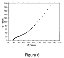
- Figure 6 is an impedance plot at 182C.
- Figure 7 is an impedance plot of an assembly containing a membrane.
- Figure 8 is an impedance plot of an assembly containing a membrane exposed to a heterborate acid.
- Figure 9(a). is a graphical representation of a cyclic voltammogram (CV).
- Figure 9(b) is a graphical representation of a CV at more negative potentials.
- Figure 10(a) is a graphical illustration of a variation of capacitance with voltage for a test electrolyte.
- Figure 10(b) is a graphical illustration of a variation of capacitance with voltage for a control electrolyte.
- Figure 11(a) is a graphical illustration of a variation of capacitance with voltage for a test electrolyte.
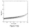
- Figure 11(b) is a graphical illustration of a variation of capacitance with voltage for a control electrolyte.
- Figure 12 is a schematic of a capacitor test cell.
- Figure 13 is a graphical illustration of constant-current voltage cycling of test and control cells.
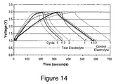
- Figure 14 is a graphical illustration of successive constant current cycling of test and control cells.
- Figure 15 is a graphical illustration of charging capacitance of test and control cells.
- the invention relates to an improvement in conducting media for energy storage devices including, without limitation, battery, in particular lithium and lithium ion batteries, capacitor and fuel cell applications.
- a battery is comprised of an oxidizing positive electrode or cathode, a reducing negative electrode or anode, separated by a porous separator and electrochemically connected via an ion conducting medium or electrolyte. The electrolyte when in the form of an organic polymer can also function as a separator.
- a lithium ion battery comprises lithium containing positive and negative electrodes and a lithium ion conducting medium.
- a magnesium battery comprises magnesium containing electrodes and magnesium conducting media.
- a fuel cell is comprised of a hydrogen anode, or negative electrode, an oxygen cathode, or positive electrode and a proton conducting medium.
- a capacitor comprises positive and negative electrodes, but which are capable of storing charge on the surface.
- the electrodes are separated by a positive and negative ion containing conducting electrolyte.
- one of the capacitor electrodes can undergo oxidation and reduction during charge and discharge.
- the improvement in said conducting media resides in the use of a fluoroborate or fluoroheteroborate comprising the formula: M a Q•nH 2 O where, M comprises a cation, Q comprises a fluoroborate or fluoroheteroborate anion; the acid or acid salt is associated with n molecules of water of hydration.
- the anion may be monovalent or divalent, the cation may have an oxidation state ranging from +1 to +3; from this, the subscript a is so chosen as to render the formula electrically neutral.
- a and n are zero.
- M comprises any cation which is stable over the electrochemical window of the electrochemical cell and serves as an appropriate ion carrier for the particular cell application, e.g., M comprises lithium for a lithium or lithium ion cell, and M comprises magnesium for a magnesium cell, M comprises calcium for calcium cell and M comprises aluminum for an aluminum cell.
- the proton conducting medium comprises a mixture of this acid and the acid salt, HaM b Q•nH 2 O in molar proportions ranging from about 1:10 to about 100:1 of the acid to the acid salt, typically about 1:1 to about 10:1 of the acid to the acid salt.
- the proton may be free (as H + ) or solvated with one or more water molecules eg. as the hydroxonium ion, H 3 O + .
- M comprises any cation which is stable over the entire electrochemical window of the fuel cell.
- M has to be resistant to reduction by hydrogen at the fuel cell's anode and to oxidation by oxygen at the fuel cell's cathode.
- the tabled electrochemical reduction potentials (E° values) as in the CRC Handbook of Chemistry and Physics, D. R. Lide (Ed) 74th Ed ; hereby incorporated by reference. pages 8-21 to 8-31, may be used as an approximate guide for choosing an appropriate cation.
- Examples are the monovalent and divalent cations respectively of Groups 1 and 2 and the Periodic Table eg.
- Tertiary and quaternary alkyl or mixed alkyl, aryl ammonium ions of formula R 3 NH + and R 4 N + respectively, are relatively reduction and oxidation resistant and would therefore also be useful in electrochemical supercapacitor applications or as cations which comprise the proton conductor.
- R here comprises any suitable alkyl, phenyl or alkyl substituted phenyl group. Additional examples can comprise at least one member selected from protonated forms of nitrogen heterocyclic or nitrogen and oxygen containing heterocyclic bases would be suitable as cations, (base)H + which comprise the proton conductor.
- nitrogen heterocyclic bases comprise at least one of pyridine, piperidine, quinoline, isoquinoline, pyrrole, indole, imidazole, benzimidzaole, imidazolidine; and N-methyl imidazole.
- heterocyclic compounds containing both N and O heteroatoms oxazole, benzoxazole, and morpholine.
- a combination of two or several different cations can be employed as the cation M for a battery electrolyte conductor, as part of an electrochemical supercapacitor, or proton conductor eg. Li + K + , Ca 2+ Li + and so on.
- the presence of the cation is not necessary for protonic conduction, but it provides an additional means of hydrating the salt and this is particularly true for the smaller (more Lewis acidic) cations, e.g., Li + which can tightly coordinate water in this case as Li(H 2 O) 4 + .
- the hydration is useful for maintaining liquidity (when this is desired) and may assist in proton transfer, provide proton conductivity pathways.
- the larger (higher radius to charge ratio) less hydrophilic cations eg. Cs + ) will tend to raise the melting point of the acid salt and yield compositions that are solid state protonic conductors.
- the group Q comprises a member selected from the following fluoroborate (i) and heterofluoroborate (ii and iii) anions (e.g., the structure of which is illustrated in Figure 1):
- the heteroborates of groups ii and iii above have the advantage of being easily functionable at their nitrogen and carbon atom sites respectively.
- the fluorocarboranes (iii) are the most weakly coordinating anions from which follows that their protonated forms (HQ •nH 2 0) will be the strongest acids implying a higher mobility and therefore a higher conductivity for their (single) proton.
- a lithium or lithium ion secondary battery capable of multiple cycles of charging and discharging, is typically dependent on an electrolyte conducting solution carrying lithium ions.
- Two desirable properties for lithium battery electrolyte solutions are: (a) a high conductivity in a non-aqueous ionizing solution, and (b) chemical stability to heat, hydrolysis and particularly to electrochemical cycling over a wide potential range.
- Other desired features of lithium electrolyte solutions include: high flash point; low vapor pressure; high boiling point; low viscosity; good miscibility with solvents customarily employed in batteries, especially ethylene carbonate, propylene carbonate and alpha-omega-dialkyl glycol ethers; good electrical conductivity of their solutions over a wide temperature range, and tolerance to initial moisture content.
- the lithium salt can be carried in an aprotic solvent.
- these aprotic solvents are anhydrous, and anhydrous electrolyte solutions are useful.
- aprotic solvents or carriers for forming the electrolyte systems comprise at least one of dimethyl carbonate, ethyl methyl carbonate, diethyl carbonate, methyl propyl carbonate, ethyl propyl carbonate, dipropyl carbonate, bis(trifluoroethyl) carbonate, bis(pentafluoropropyl) carbonate, trifluoroethyl methyl carbonate, pentafluoroethyl methyl carbonate, heptafluoropropyl methyl carbonate, perfluorobutyl methyl carbonate, trifluoroethyl ethyl carbonate, pentafluoroethyl ethyl carbonate, heptafluoroprop
- the electrolyte system of the present invention can comprise an aprotic gel polymer carrier/solvent.
- Suitable gel polymer carrier/solvents comprise at least one of polyethers, polyethylene oxides, polyimides, polyphosphazines, polyacrylonitriles, polysiloxanes, polyether grafted polysiloxanes, derivatives of the foregoing, copolymers of the foregoing, crosslinked and network structures of the foregoing, blends of the foregoing, and the like, to which is added an appropriate ionic electrolyte salt.
- gel-polymer carrier/solvents comprise those prepared from polymer matrices derived from polypropylene oxides, polysiloxanes, sulfonated polyimides, perfluorinated membranes (NafionTM resins), divinyl polyethylene glycols, polyethylene glycol-bis-(methyl acrylates), polyethylene glycol-bis(methyl methacrylates), derivatives of the foregoing, copolymers of the foregoing, crosslinked and network structures of the foregoing.
- the solution comprising a combination of aprotic solvent and fluorinated lithium dodecaborate salt employed for forming the lithium based electrolyte for the lithium battery typically will have a concentration of lithium fluorododecaborate of at least 0.05 to 1 molar and typically from about 0.1 to about 0.6 molar.
- concentration of lithium fluorododecaborate typically at least 0.05 to 1 molar and typically from about 0.1 to about 0.6 molar.
- Useful ranges of lithium salt in the electrolyte are from about 0.2 to about 0.5 molar. Higher concentrations tend to become too viscous and, the bulk conductivity characteristics can be adversely affected.
- solutions formed from lithium based fluoroborates having an increased concentration of halogen atoms other than fluorine may show an increase viscosity to the lithium fluoroborates having higher fluorine content.
- lithium based salts can be used in combination with the lithium based fluoroborates, e.g. LiPF 6 , lithium perchlorate, lithium hexafluoroarsenate, lithium trifluoromethylsulfonate, lithium tetrafluoroborate, lithium bromide, and lithium hexafluoroantimonate as desired.
- the salts of this invention can be used in combination with other salts in any effective amounts. Typically, if such salts are used, they are added in relatively small amounts to the inventive lithium fluoroborate based electrolyte or the lithium based fluoroborates are added to the batteries employing other based lithium salt in small amounts.
- the lithium battery employing the lithium fluorododecaborate electrolyte can be any using a suitable lithium containing cathode and a negative anode.
- the negative electrodes for use in a lithium secondary battery typically can be based generally upon non-graphitizing carbon, natural or artificial graphite carbon, or tin oxide, silicon, or germanium compound. Any of the conventional anode compositions may be used in combination with the lithium fluorododecaborate electrolytes here.
- the positive electrode for use in lithium secondary batteries typically can be based upon a lithium composite oxide with a transition metal such as cobalt, nickel, manganese, among others, or a lithium composite oxide, part of whose lithium sites or transition metal sites is replaced with cobalt, nickel, manganese, aluminum, boron, magnesium, iron, copper, among others, or iron complex compounds such as ferrocyan blue, berlin green, among others.
- Specific examples of lithium composites for use as positive electrodes comprise LiNi 1-x Co x O 2 and lithium manganese spinel, LiMn 2 O 4 .
- the former composite presents significant safety concerns due to the very high oxidizing potential of Ni(IV).
- the latter composite is significantly less oxidizing than the Ni(IV) lithium battery and leads to far better redox kinetics and much higher power densities than the nickel cobaltate cathode.
- the separator for the lithium battery can comprise a microporous polymer film.
- polymers for forming films comprise: nylon, cellulose, nitrocellulose, polysulfone, polyacrylonitrile, polyvinylidene fluoride, polypropylene, polyethylene, polybutene, among others.
- Ceramic separators, based on silicates, can also be used.
- the battery is not limited to particular shapes, and can take any appropriate shape such as cylindrical shape, a coin shape, and a square shape.
- the battery is also not limited to particular capacities, and can have any appropriate capacity for both small appliances and power storage or electric cars.
- Some retention of water is necessary for providing a mechanism for proton transport and also to provide required liquidity, if required.
- the proton conductor, H a M b Q•nH 2 O can be either solid or liquid at the operating conditions of the device.
- the said liquid is held in an inert porous support and functions both as a proton carrier and as a membrane which separates the anode and cathode compartments of the cell.
- a liquid is expected to be advantageous because of its expected higher conductivity due to an expected more facile proton transfer in a liquid medium.
- the hydrate level (n) is increased sufficiently to generate a liquid.
- n is at least 6, generally at least 8 and usually at least 10. As described below, the presence of other cations will effect the melting point and the state of hydration.
- the proton conducting medium can also comprise a mixture comprising the acid H a Q•nH 2 O and the salt M b Q•nH 2 O in molar proportions ranging from about 1:10 to about 100:1 of the acid to the salt, typically about 1:1 to about 10:1 of the acid to the acid salt.
- Solid state proton conductors have the advantage of also providing without the need of other components, the required physical separation between the fuel cell's compartments.
- Solid forms of the proton conductor of formula H a Q•nH 2 O can be used in the fuel cell. Solid forms generally exist when n is less than 6.
- the polyhedral fluoroborate, H a M b Q•nH 2 O proton conductors can be generated by a direct fluorination of the corresponding polyhedral hydridoborates in a liquid medium. Or by the direct fluorination of a selected salt of a closo -borohydride followed by an acid metathesis; the replacement of the cation with a proton as described in Examples 3 to 5.
- a partial exchange of such a salt, M b Q•nH 2 O with protons leads to the acid salt of formula 1, namely H a M b Q•nH 2 O.
- fluorine is typically diluted with an inert gas, e.g., nitrogen, to a concentration of from about 10 to about 40 %.
- the liquid medium or carrier for the hydridodoborate salt is one that is not substantially reactive with fluorine.
- Conventional mediums comprise liquid hydrogen fluoride, HF.
- Other liquids can be used in the process and comprise water, organic acids such as formic acid, acetic acid, trifluoroacetic acid and the like.
- the acidity of the liquid medium can affect the solubility of the precursor hydridoborates and the fluorinated hydridoborate salt and effect an acidity change therein. It is desirable for the medium be designed to maintain soluble both the hydridoborates and the fluorinated hydridodoborate salt product.
- Radical scavengers can be used in the fluorination process to reduce byproduct formation and improve reaction efficiency.
- radical scavengers appear to limit the formation of hydrogen peroxide, or HOF, which may be generated with fluorine.
- Radical scavengers are used where organic acids, such as formic acid, are employed to adjust acidity, and inhibit the side-reaction of fluorine with the solvent, thereby improving fluorination efficiency.
- examples of radical scavengers comprise oxygen, and nitroaromatics. The introduction of a small amount of air to the liquid medium removes free radicals generated in the direct fluorination of the hydridodoborate salts.
- Fluorination of the polyhedral hydridoborate anions can be carried out over a temperature range sufficient to maintain liquid phase conditions.
- the temperature is from about -30 to about 100°C, typically from about 0 to about 20°C.
- Pressures during fluorination are such as to maintain liquid phase conditions, typically atmospheric.
- the extent of fluorination of the polyhedral hydridoborates and of the borate salts can be controlled by varying the reaction conditions and reagent stoichiometries.
- a mixed halogen fluoroborate Q where Z comprises Cl or Br; or Cl or Br and H
- the partially fluorinated product is reacted with Cl 2 or Br 2
- Cl 2 or Br 2 e.g., US Patent No. 3,551,120 ; hereby incorporated by reference, 1970
- Closo-borates comprising OH substituient groups can be prepared by treatment of a polyhedral hydro- closo -borate with 40% sulfuric acid [Peymann, T.; Knobler, C. B.; Hawthorne, M. F. Inorg. Chem. 2000, 39, 1163; hereby incorporated by reference]
- the hydrated fluoroborate acids H a Q•xH 2 O. (where x is at least 5 and more usually x is at least 8) can be formed from the fluoroborate salts.
- One method involves the treatment of an aqueous solution of the barium salts, BaQ or BaQ 2 , or an aqueous solution of the calcium salts, CaQ or CaQ 2 with sulfuric acid, or with aqueous HF, and removing the insoluble salts, BaSO 4 and CaF 2 by filtration. Water can be removed by distillation from the aqueous solution of the hydrated fluoroborate until the desired acid/water ratio is achieved.
- the fluoroborate hydrate of the formula, H a M b Q•nH 2 O can be used alone or it can be mixed to form a solution with anhydrous phosphoric acid or other proton conducting compositions to produce a desired proton conducting medium.
- a fluoroborate acid/phosphoric acid medium, whether the fluoroborate is in liquid or solid form, can be used in any effective amount. Typical ratios are from about 0:2 to about 10:1 weight parts fluoroborate proton conductor per weight part phosphoric acid.
- Solid forms of the proton conductor can be used as additives to the inventive composition for varying as desired, the melting points of these mixtures.
- the fluoroborate acids and acid salts can both be also blended with various polymers to form composite membranes.
- the blending may be accomplished by imbibing the polymer with a solution of the acid or salt in polar organic solvent, for example N-methyl pyrrolidone, and then at least partially removing the solvent from the resulting composite material.
- polar organic solvent for example N-methyl pyrrolidone
- a polymeric film electrolyte may be cast from a solution that contains both the polymer and the acid or acid salt in a mutual solvent.
- the polymers suited for forming composite membranes may comprise polymeric perfluorosulfonic acids, polyethylene oxide, polyimides, polysulfones, in general polymeric matrices that comprise carbonyl, amine, ether, sulfone or sulfoxide polar functional groups that may be expected to have an interaction with the proton or metal cation of the electrolyte.
- Nitrogen or oxygen atom containing polymers such as polyvinylpyridine, polyaniline, polybenziminazole, polybenzoxazoles, mixtures thereof, among others, are useful, where the interaction of the basic nitrogen or oxygen with the proton conductor is expected to facilitate the formation of a suitable blend of the two components.
- the liquid proton conductors can also be impregnated into a porous matrix, such as a microglass fibers, silicon carbide, boron nitride, or porous carbon materials, resulting in a proton conducting separation membrane. Physical blends of the solid proton conductors and the latter solid materials could also be employed.
- the group Q is attached to a polymer backbone via a chemical bond.
- All of these polymers typically rely on negatively charged Q functionalities (polymer-Q - ) as the stationary charge for mobile cations, such as H + , Li + , Na + , Mg 2+ and others.
- Q functionalities polymer-Q -
- These polymers can be used as ion-conducting electrolytes in lithium batteries, fuel cells and other electrochemical devices.
- the polymers with chemically attached Q functionalities are expected to have effective ion conductivities due to low coordinating abilities of the Q functionalities of this invention.
- These polymers can also be blended with fluoroborate salts, acids and/or their solutions to form gel electrolytes and to improve their ion conductivities.
- the polymer backbone may comprise at least one member selected from the group perfluoroalkyl, perfluoroethers, styrene, styrene-butadiene, fluorinated styrene, polyethers, polyethylene oxides, polyimides, polyphosphazines, polyacrylonitriles, polysiloxanes, polyether grafted polysiloxanes, derivatives of the foregoing, copolymers of the foregoing, crosslinked and network structures of the foregoing, blends of the foregoing, among others.
- the anion may be chemically attached to the polymer backbone via a boron-oxygen-carbon-polymer bond.
- Q comprises closo- ammoniofluoroborate (-1) anion compositions of formula ((R'R''R''')NB 12 F x Z (11-x) ) -
- the Q is attached to the polymer backbone via boron-nitrogen-polymer bond or via boron-oxygen-polymer bond.
- Q comprises closo -monocarborate (-1) anion compositions of formula (R'''CB 11 F x Z (11-x) ) -
- the Q is attached to the polymer backbone via a boron-carbon-polymer bond or via a boron-oxygen polymer bond.
- the proton conductors of this invention can be used in any suitable device where H 2 (gas) is in an electrochemical equilibrium with a proton source. This is one of the elementary processes in a fuel cell and the basis for the present proton conductors' utility herein.
- the conducting media can also be employed in hydrogen gas sensor devices where the H 2 partial pressure is a function of the measured potential of an electrode in contact with the proton conducting medium.
- the proton conductors are useful for an electrolysis of water to produce H 2 and O 2 particularly at higher temperatures in the presence of steam where higher electrochemical efficiencies may be realized; these devices here are essentially fuel cells in reverse (e.g., as described in "Proton Conductors" ibid Chapter 32; hereby incorporated by reference).
- the salt M b Q•nH 2 O dissolved in water can be used as an aqueous electrolyte.
- it is useful to employ high polarity organic solvents for the salt in an anhydrous form (n 0) compositions (e.g., which can have a wider range of electrochemical stability).
- the energy stored in an electrochemical supercapacitor is typically proportional to the square of the voltage it is desirable that both the solvent and salt's counteranions posses the maximum electrochemical stability.
- Suitable aprotic relatively polar organic solvents having a high electrochemical decomposition potential comprise the following: acetonitrile, propylene carbonate, ⁇ -butyrolactone, ⁇ -valerolactone, N,N-dimethylformamide, dimethylsulfoxide, sulfolane, nitromethane, N,N-dimethylacetamide, 3-methoxypropionitrile, 1-methyl-2-pyrrolidinone, and ethylene carbonate as a component in mixtures of one or more of the above.
- the electrolyte system for the electrochemical capacitor of the present invention can comprise an aprotic gel polymer carrier/solvent.
- Suitable gel polymer carrier/solvents can comprise at least one of polyethers, polyethylene oxides, polyimides, polyphosphazines, polyacrylonitriles, polysiloxanes, polyether grafted polysiloxanes, derivatives of the foregoing, copolymers of the foregoing, crosslinked and network structures of the foregoing, blends of the foregoing, among others , to which is added an appropriate ionic electrolyte salt.
- gel-polymer carrier/solvents can comprise those prepared from polymer matrices derived from polypropylene oxides, polysiloxanes, sulfonated polyimides, perfluorinated membranes (NafionTM resins), divinyl polyethylene glycols, polyethylene glycol-bis-(methyl acrylates), polyethylene glycol-bis(methyl methacrylates), derivatives of the foregoing, copolymers of the foregoing, crosslinked and network structures of the foregoing.
- the cation M in formula M b Q for the anhydrous aprotic salt is usually stable to reduction at the most negative electrochemical potential.
- the choice of M b can affect the solubility of the parent salt M B Q in the aprotic solvent.
- Suitable cations are in general, tetraalkylammonium, + NR 1 R- 2 R 3 R 4 , tetralkylphosphonium, + PR 1 R 2 R 3 R 4 salts where R 1 to R 4 are independently chosen from any linear or branched alkly group such as methyl, ethyl, n-propyl, iso-propyl and n-butyl groups.
- Useful cations of this class comprise tetramethylammonium, + N(CH 3 ) 4 , tetrabutylammonium + N(nBut) 4 and tripropylmethylammonium, + N(n-Pr)Me.
- Other "mixed” cations of this class may be prepared as described in the reference: K. Ku et al "Quaternary Onium Salts as Nonaqueous Electrolytes for Electrochemical Capacitors", J. of Electrochemical Soc., 148, (3), A267 (2001 ); hereby incorporated by reference.
- Organic cations of a cyclic or polycyclic structure may be used.
- examples of such cations comprise: quinuclidinium, N-methyl pyridinium, and the doubly charged ions of: N,N-dialkyl-1,4-diazabicyclo[2.2.2]octanediium (DADABCO) and the cationic N-methyl derivatives of hexamethylenediamine.
- DADABCO N,N-dialkyl-1,4-diazabicyclo[2.2.2]octanediium
- Lithium, magnesium cations and the other Group 1 and Group 2 cations may be utilized in electrochemical capacitors to electrochemical potentials that are well positive of the voltage at which the metals are expected to deposit.
- the previously described quaternary ammonium organic cations can also be used in electrochemical capacitors.
- Figure 10(a) from Example 19 shows a cyclic voltammogram for a 0.026M solution of ((CH3)4N]2[B12F12] in 1:1 EC/DMC where capacity (in Farads/gm of the active carbon electrode material) is plotted against voltage. From -1V to about 1.5V versus Pt there is a monotonic increase in capacity with a sharp up-turn at ⁇ 1.5V. On the other hand, for the [N(CH3)4][BF4] in 1:1 EC/DMC control there is only a monotonic increase in capacity to 2.5V ( Figure 11(a). The increase in capacity for the former is believed to be associated with the aforementioned redox reaction occurring at > about 1.5V: [B 12 F 12 ] 2- - e - ⁇ [B 12 F 12] -
- Examples 19 and 20 there was one porous carbon working electrode.
- a typical capacitor storage device comprises two symmetrical porous carbon electrodes that are separated by a thin porous separator which contains the electrolyte (e.g., see Fig. 12).
- a typical capacitor storage device comprises two symmetrical porous carbon electrodes that are separated by a thin porous separator which contains the electrolyte (e.g., see Fig. 12).
- such a device was constructed with the porous separator imbibed with a 0.2M solution of the test electrolyte [N(C2H5)3CH3]2[B12F11.3H0.7] in 1:1 PC/DMC.
- a second or control device was made using the 1 M [N(C2H5)4][BF4] in 1:1 PC/DMC electrolyte.
- Tables 1 and 2 the test and control capacitors have similar capacities at 1V and 2V (e.g., at 2V the capacity was: 104F/g for the test vs. 118
- the capacitor containing the inventive fluorododecaborate electrolyte functions at least comparably to the control; enhanced capacities and charge/discharge rates can be achievable with higher concentrations of the salt.
- This redox phenomenon provides an unexpected opportunity to augment the energy storage of a double layer capacitor by operating at the higher voltage which encompasses the redox reaction i.e. up to about 5V vs Li/Li+.
- the greater energy storage comes from the higher potential but additionally from a Faradaic transfer of charge from the adsorbed fluoroborate anions to the electrode.
- a Faradaic transfer of charge from the adsorbed fluoroborate anions to the electrode thus over the approximately 0.5V potential range one electron is transferred to and from the electrode surface per mole of [B12F11.3H0.7]2-.
- the increased energy storage can be about 0.5V x 96,500 coulombs/mole or ⁇ 40 kJ/mole.
- a double layer capacitor operating in this manner is an example of a "Faradaic process" electrochemical capacitor having the evident advantage of a potentially higher energy storage capacity.
- Faradaic process may also occur at the negative electrode surface by utilizing a redox active cation, for example the europium 3+/2+ couple for which E° is at -0.36V versus H2/H+ or, the Sm3+/Sm2+ couple which is at -1.55V versus H2/H+ or the Pm3+/Pm2+ couple at -2.6V versus H2/H+ (or 0.44V vs Li+Li).
- a redox active cation for example the europium 3+/2+ couple for which E° is at -0.36V versus H2/H+ or, the Sm3+/Sm2+ couple which is at -1.55V versus H2/H+ or the Pm3+/Pm2+ couple at -2.6V versus H2/H+ (or 0.44V vs Li+Li).
- a lithium based salt for an electrolyte solution which has extraordinary chemical, thermal, and hydrolytic stability; an ability to use a lithium-based electrolyte of optimal electrochemical stability; an ability to use a lithium electrolyte solution which can be used at a low lithium based salt concentration, e.g., one-half the concentration of many other lithium based salts, e.g.,LiPF6;and, an ability to form low viscosity, low impedance lithium electrolyte solutions which can be recycled.
- a low lithium based salt concentration e.g., one-half the concentration of many other lithium based salts, e.g.,LiPF6
- a fuel cell In a fuel cell an ability to use a proton conductor in liquid form having low volatility and low viscosity; an ability to use a proton conductor having excellent affinity for water at elevated temperatures, e.g., 80 to 250°C and enabling fuel cell operation at the temperatures (150-250°C) of this range where the anode is less sensitive to CO poisoning.
- an electrochemical supercapacitor an ability to use a salt for an electrolyte solution which has extraordinary chemical, thermal, and hydrolytic stability; an ability to use a salt for an electrolyte solution of a wide electrochemical potential range enabling maximum energy storage. an ability to further augment the storage capacity of the capacitor via a Faradaic transfer of charge due to a reversible Q2- ⁇ Q-+ e redox process that is a characteristic of the fluoroborate compositions of this invention. an ability to limit the voltage of a capacitor in a bank of capacitors connected in a series.
- 100% of the desired F 2 (142 mmol) was added as a mixture of 10%F 2 /10%O 2 /80%N 2 , a colorless solution remained. Further fluorination (3%) at 30°C resulted in precipitation of solid from solution. Solvents were evacuated overnight, leaving 5.1 g of a colorless, friable solid.
- This example demonstrates preparation of H 2 B 12 F 12 x n H 2 O by direct fluorination of H 2 B 12 H 12 x n H 2 O.
- This example demonstrates preparation of highly fluorinated hydroxy-substituted borate cluster salts.
- a colorless slurry containing ⁇ 4.0 g (17 mmol) of K 2 B 12 H 11 (OH) prepared by a standard literature method was dissolved in 15 ml formic acid and was treated with 10%F 2 /10%O 2 /80%N 2 (240 mmol F 2 total, 27% excess) at -10 to -5°C.
- Analysis of the crude product by 19 F NMR revealed primarily B 12 F 11 (OH) 2- (55%), and B 12 F 10 H(OH) 2- (35%) and approximately 5% of dihydroxy impurities.
- This example demonstrates preparation of highly fluorinated hydroxy-substituted borate cluster salts.
- a colorless slurry containing 2.2 g (8.7 mmol) K 2 B 12 H 10 (OH) 2 prepared by a standard literature method was dissolved in 8 ml formic acid and treated with 10%F 2 /10%O 2 /80%N 2 (114 mmol F 2 total, 30 % excess) at -10 to -5°C.
- Analysis of the crude product by 19 F NMR revealed primarily B 12 F 10 (OH) 2 2- (30%), and B 12 F 9 H(OH) 2 2- (60%) and approximately 10% of trihydroxy impurities.
- the purpose of this example is to illustrate the preparation of the hydrated acid (H 3 O) 2 B 12 F x H 12-x .
- a solid Ba(OH) 2 8 H 2 O (2.53 g, 8.0 mmol) was added to a suspension of [Et 3 NH] 2 [B 12 F 12 ] (4.50 g, 8.0 mmol) in 50 ml of water, and triethylamine was distilled off under reduced pressure. As triethylamine was removed, an aqueous solution containing BaB 12 F 12 was formed. This aqueous solution of BaB 12 F 12 was treated with aqueous H 2 SO 4 , and BaSO 4 precipitate was removed by filtration. Water was distilled off from the filtrate, and the remaining solid was dried under vacuum at 190°C for two hours.
- the solid was analyzed by gravimetric analysis.
- the solid (0.211 g) was dissolved in 10 ml of water and treated with Ph 4 PCl.
- the white precipitate that formed was washed with water and dried at 120°C for 2 hours to collect 545.2 mg of [Ph 4 PMB 12 F 12] (for H 2 B 12 F 12 •2 H 2 O the collected amount of [Ph 4 P] 2 [B 12 F 12 ] should be 550.5 mg, for H 2 B 12 F 12 •4 H 2 O the collected amount of [Ph 4 P] 2 [B 12 F 12 ] should be 504.6 mg).
- the composition of a solid acid was H 2 B 12 F 12 R''2 H 2 O.
- the IR spectrum of the fluorolube mull of the solid acid contains a broad intense OH stretch at 3084 cm -1 , a lower intensity OH stretch at 3269 cm -1 , and an HOH band at 1610 cm -1 , all attributive to (H 3 O) + cation.
- the above described acid also can be produced by a method which includes eluting a salt of the anion via an ion-exchange column in H + form and removing water under reduced pressure.
- that method is time-consuming and requires evaporation of large amounts of water. It also results in contamination of the product acids with organic impurities.
- a 2032 button cell battery configuration was used employing a lithium foil - electrode ⁇ 0.4-0.5M Li 2 B 12 F 12 in EC/DMC ⁇ LiNi 0.8 Co 0.15 Al 0.05 O 2 (+ electrode).
- the cell was pulse charged and discharged using an Arbin Instruments BT4 series potentiostat to assess the area specific impedance (ASI) of the cell.
- ASI area specific impedance
- This purpose of this example is to determine if the acid, (H 3 O) 2 B 12 F 12 , is stable under humid air up to 250°C under inert atmosphere and whether the acid absorbs water at 250°C under low water vapor pressure (in this case only 24 torr), an important feature in fuel cells.
- the solid acid prepared as above was exposed to air for 18 hours. TGA of the acid was performed under dry air. To determine water adsorption at these conditions, the airflow was switched between the dry air and the humid air (air bubbled through water at ⁇ 25°C), Figures 2-4.
- the purpose of this example is to determine the stability of H 2 B 12 F 12 •n H 2 O compositions toward hydrogen at high temperatures, an important feature in fuel cells.
- the acid H 2 B 12 F 12 •2 H 2 O, and a mixture of H 2 B 12 F 12 •H 2 O with 5% Pt on carbon ( ⁇ 5 /1 mass ratio) were heated at 200°C for 14 days at 50 psig (at 25°C) of 100 % H 2 and 225 psig of water vapor pressure.
- the fluoroborate anion was stable according to the 19 F and 11 B NMR of the acid solutions.
- the acids such as H 2 B 12 F 12 •n H 2 O have shown a remarkable stability toward hydrogen at the temperatures up to 200°C. Solid acid proton conductors based on CsHSO 4 typically degrade under hydrogen atmosphere at these temperatures.
- the purpose of this example is to determine the conductivity of H 2 B 12 F 12 •n H 2 O as a liquid proton conductor from 20 to 200°C at water vapor pressures above 250 torr.
- the acid was placed into a glass cell, which was connected to a water reservoir through a heated tube. The system was placed under vacuum and the temperature of the water reservoir was varied to change the water vapor pressure in the system, which was also measured by the vacuum gauge.
- the acid was a liquid (n was equal to 8) at temperatures between 20 to 200°C and water vapor pressure above 250 torr.
- the conductivity of the liquid acid was determined using a two-pole CDC741T conductivity cell. The results are shown in Table 1. Table 1.
- Table 1 show that the composition retains water at low humidity with little reduction in conductivity.
- the test is relevant to proton transfer between electrodes of a fuel cell. A base of at least 100-150 mS/cm minimum is normally desired, and these compositions significantly exceed that conductivity level.
- the acid H 2 B 12 F 12 •n H 2 O retains enough water to remain in a liquid phase up to 200°C at a water vapor pressure of only 250 torr. This property is dramatically different from the behavior of a similar chloroborate acid H 2 B 12 Cl 12 •n H 2 O, which solidifies above 145°C and a water vapor pressure of 600 torr.
- the acid, H 2 B 12 F 12 •nH 2 • also showed a higher conductivity (350 mS/cm) at lower humidity level (water vapor pressure 200 torr), than the conductivity of H 2 B 12 Cl 12 •n H 2 O (239 mS/sm at water vapor pressure 600 torr).
- the purpose of this example is to demonstrate that mixtures of fluoroborate acid and anhydrous phosphoric acid form melts, which have high proton conductivity even under inert atmosphere.
- Solid mixtures (H 3 O) 2 B 12 F 12 / 2 H 3 PO 4 ( ⁇ 67 weight % of (H 3 O) 2 B 12 F 12 ), (H 3 O) 2 B 12 F 12 / 4 H 3 PO 4 ( ⁇ 50 weight % of (H 3 O) 2 B 12 F 12 ), and (H 3 O) 2 B 12 F 12 / 12 H 3 PO 4 ( ⁇ 25 weight % of (H 3 O) 2 B 12 F 12 ) were prepared under inert atmosphere. The mixtures were heated under inert atmosphere at 60 - 140°C and all formed clear solutions above 100°C.
- the 1:2 mixture melt crystallized at ⁇ 100°C.
- the conductivities of the melts under inert atmosphere are shown in Table 2.
- Conductivity of the phosphoric acid / fluoroborate acid melts at 100°C under inert atmosphere.
- the conductivity of the melts increases by the addition of small amounts of water.
- the purpose of this example is to determine the thermal stability of phosphoric acid/fluoroborate acid melts.
- the purpose of this example is to determine the oxygen reduction kinetics of aqueous solutions of the fluoroborate acid, and its mixtures with phosphoric acid.
- Linear sweep voltammograms of aqueous acid solutions were recorded at 1400 rpm on a BAS rotating disc electrode apparatus with a CH Instruments Electrochemical Workstation potentiostat.
- the acid solutions were saturated with 1 atm of pure O 2 for at least 15 min before potential sweeps were made and O 2 purge was continued during the measurements.
- Several cyclic voltammetry scans were also applied between 1.0 and -0.2 V prior to collecting linear sweep data, to remove traces of electro-active impurities in the system.
- the working electrode was a Pt rotating disc electrode, which was polished, washed with distilled water, and dried before each new acid solution was measured.
- the reference was a Ag/AgCl electrode, and a Pt wire counter electrode was used.
- the graph, Figure 5 shows better oxygen reduction kinetics for the hydrated fluorododecaborate acids and its mixtures with phosphoric acid than aqueous solutions of a neat phosphoric acid and they also result in a higher current at the same potential. Strong anion-absorption is indicated by a shift in oxygen reduction to increasingly negative potentials. This overpotential is associated with the greater distance required for electron transfer through the thicker absorption layer interface and interference of reactant absorption at the electrode.
- the limiting current was almost three times higher for a 60% aqueous solution of a 1:1(wt.%) H 2 B 12 F 12 and H 3 PO 4 mixture compared with the limiting current of 60 % H 3 PO 4(aq) at the same potential, suggesting higher oxygen solubility in the solution containing the fluoroborate acid.
- the solutions of fluoroborate acid proton conductors have better oxygen reduction kinetics on a platinum catalyst than solutions of neat phosphoric acid.
- the kinetics may result in fuel cells with higher power density.
- the resulting mixtures show much less adsorption on the platinum electrode than does neat phosphoric acid.
- the purpose of this example is to demonstrate the preparation of proton conductive solid membranes from fluoroborate acids.
- a glass fiber paper disk ( ⁇ 125 ⁇ m thickness, diameter ⁇ 10 mm, 5.5 mg) was soaked for 15 minutes in a 30 % solution of (H 3 O) 2 B 12 F 12 .
- a membrane with thickness 550 ⁇ m and 49 mg weight ( ⁇ 90 wt % of the solid acid) was obtained.
- a glass fiber disk was soaked in ⁇ 10 % solution of (H 3 O) 2 B 12 F 12 and the disk was dried at 120°C for two hours, a membrane with thickness 225 ⁇ m and 18 mg weight was obtained.
- the membranes dried at 120°C for two hours, were pressed between the two gold disks, an alternating voltage (amplitude of 10 mV) in the frequency range 0.1 Hz to 0.1 MHz was applied to the membranes, and the complex impedance was measured Figure 6.
- the membrane resistances were obtained by extrapolating the impedance data to the real axis on the high frequency side.
- the resistance of a 550 ⁇ m membrane was 30000 ⁇ at 27°C (conductivity is ⁇ 1.2 ⁇ S/cm), but the resistance at 182°C was three orders of magnitude lower 23 ⁇ , (conductivity is ⁇ 1.6 mS/cm),
- This example demonstrates the preparation of proton conductive solid membranes from fluorinated closo-heteroborate acids.
- a mixture of compounds Cs(CB 11 F 11 H) (0.3g) and [N(C 4 H 5 ) 4 ][CB 11 F 11 H] (0.5g) was dissolved in 30 ml of a 1:1 mixture of methanol and acetonitrile. The combined mixture was eluted through a column packed with Amberlyst-15 cation exchange resin and the liquid fraction was collected in its acidic form. 10 ml of Dl water was added to the column fraction and the solvents were removed from the elute under vacuum. The remaining acid was reconstituted to 5.0 ml in water.
- a glass fiber paper disk ( ⁇ 125 ⁇ m thickness, diameter - 20 mm, weight ⁇ 20 mg) was soaked in the solution of the fluorinated closo-heteroborate acid. After drying for two hours at 120 °C, a solid disk containing - 50 wt % of the acid and ⁇ 50 wt % of the glass fibers was obtained. A solid disk containing ⁇ 90 wt % of the acid was obtained when the glass fiber paper disk was soaked in more concentrated acid solution and dried at 120 °C for two hours.
- a glass fiber disks containing fluorinated heteroborate acid HCB 11 F 11 H x n H 2 O were slightly pressed between two 15 x 0.5 mm stainless steel disks and dried for 24 h at 120 °C.
- the thickness of the solid membranes containing fluorinated heteroborate acid was 0.37 mm.
- the membrane assemblies were sealed into button cells. The cells were heated to various temperatures and the resistance of the membranes was determined by extrapolating the complex impedance data to the real axis on the high frequency side, Figures 7 and 8.
- Conductivities of the membrane composed of ⁇ 50/50 wt % of the glass fibers and fluorinated closo-heteroborate acid were: 0.5 ⁇ S/cm at 22 °C, 0.02 mS/cm at 100 °C, 0.04 mS/cm at 112 °C, and 0.1 mS/cm at 140 °C.
- Conductivity of the membrane composed of ⁇ 10/90 wt % of the glass fibers and fluorinated closo-heteroborate acid was about the same at RT, but it was much higher at elevated temperatures: 0.7 ⁇ S/cm at 22 °C, 0.47 mS/cm at 120 °C, and 3.5 mS/cm at 145 °C.
- This example illustrates a cyclic voltammagram (CV) of the electrochemical redox properties of a solution of the title salt over a range of potentials.
- CV cyclic voltammagram
- the preparation of the electrolyte salt was performed as described in Example 8.
- the supporting electrolyte was 0.1M [N(C4H5)4][BF4] in 3:7 ethylene carbonate:dimethylcarbonate (EC:DMC).
- EC:DMC ethylene carbonate:dimethylcarbonate
- the counter electrode was platinum wire and the reference electrode was a Ag wire.
- Figure 9(a) shows the CV from 0 V to 3 V (vs. Ag wire).
- Figure 9(b) shows the CV from 0 V to -2.5 V (vs.
- the potential window ranges from -1.2 V to approximately 1.5V for double layer charging without faradaic reactions.
- the region between 1.5 V and 2 V comprises the faradaic oxidation and reduction of the [N(C4H5)4]2[B12F11H] salt.
- the purpose of this example is to demonstrate the use of the tetramethylammonium fluorododecaborate salt, [N(CH3)4][B12F11H] in an electrochemical supercapacitor device.
- the laboratory test device consisted of an electrochemical cell with three closely spaced electrodes: 1. A working electrode consisting of a porous carbon film on a porous aluminum metal grid, 2. A Pt wire counterelectrode and 3. A Pt quasi-reference electrode.
- the porous carbon film was prepared by depositing a slurry of 77% active carbon, 8.5% carbon SP and 14.5% polyvinylidine fluoride and dibutylphthalate (DBP) in acetone onto an aluminum grid.
- DBP dibutylphthalate
- Figure 10(a) shows a plot of capacitance as a function of potential for 0.026M [N(CH3)4]2[B12F12] in a 1:1 ethylene carbonate (EC)/dimethylcarbonate (DMC) solvent.
- EC ethylene carbonate
- DMC dimethylcarbonate
- the control electrolyte shows an approximately linear increase in capacity from -1 to 2.5 volts (Fig. 10(b).
- [N(CH4)4][B12F12] the electrolyte of the present invention shows a relatively sharp upturn in capacity at 1.5V vs. Pt. As described above, it is believed that this is due to an oxidation of the dianion [B12F12]2-to the [B12F12]- monoanion above this potential as evidenced by the cyclic voltammogram (CV) for the closely related [N(n-But)4]2[B12F11H] salt shown in Example 18.
- CV cyclic voltammogram
- test device comprising a porous carbon working electrode (-3.4 mg carbon), with Pt counter and reference electrodes as described in Example 19 was employed to evaluate a 0.06M solution of [N(C2H5)3CH3]2[B12F11.3H0.7] in 1:1 EC/DMC, in comparison with a 0.09M solution of the [N(C2H5)4][BF4] control electrolyte in the same mixture of solvents.
- Capacity data for cells utilizing the two electrolytes is presented in Figures 11(a) and 11(b) respectively.
- the control shows a monotonic increase between -1 and 2.5V vs Pt, while the test system shows a significant rise in capacity above 1 V.
- the effect is more marked than for the [N(CH3)4]2[B12F12] salt owing at least in part to the now higher concentration (0.6M vs 0.026M) of the redox-active fluorododecoborate anion.
- Symmetric capacitor test cells were fabricated using a 0.2M triethylmethyammonium fluorododecaborate, [N(C2H5)3CH3]2[B12F11.3H0.7] salt electrolyte in 1:1 PC/DMC electrolyte and activated carbon electrodes.
- the electrodes were made of a high performance activated carbon developed for the electrochemical capacitor industry containing a Teflon® binder.
- Similar capacitor test cells were fabricated using the same type of electrodes with a control electrolyte consisting of an equal volume mixture of propylene carbonate (PC) and dimethylcarbonate (DMC) containing 1.0 M tetraethylammoniumtetrafluoroborate (TEATFB) salt.
- the electrodes were dried under vacuum at 195 C for 15 hours before being transferred to a drybox, while still under vacuum, for assembly of the capacitor test cells. Separators were dried overnight at 55 oC before being transferred to the drybox.
- the electrode discs were soaked with the appropriate organic electrolyte for 10 minutes then assembled into cells using a 0.001" thick microporous separator, thermoplastic edge seal material, and conductive face-plates (Figure 12).
- the perimeter edge sealing was performed using an impulse heat sealer that minimized heat input into the cells.
- the conductive faceplates were aluminum metal with a surface treatment to prevent oxidation (as conventionally used in the lithium-ion battery industry).
- the thermoplastic edge seal material was selected for electrolyte compatibility and low moisture permeability and applied using an impulse heat sealer located directly within the drybox. Once the cells were thermosealed, they were removed from the drybox and metal plates were clamped against each conductive face-plate and used as current collectors.
- Capacitor cells were conditioned at 1.0 V for ten minutes, measured for properties, then conditioned at 2.0 V for 10 minutes and measured for properties.
- test capacitors were conditioned at 1.0 V then shorted and the following measurements were made: with a 1 kHz series resistance, charging capacitance at 1.0 V with a 500 ohm series resistance using a capacitance test box, and leakage current at 1.0 V hold at 1V then follow change after 30 minutes using a leakage current apparatus.
- test capacitors were conditioned at 2.0 V then shorted and the following measurements were made: 1 kHz equivalent series resistance (ESR), charging capacitance at 2.0 V with a 500 ohm series resistance, leakage current at 1.5 and 2.0 V after 30 minutes using the leakage current apparatus, and electrochemical impedance spectroscopy (EIS) measurements at 2.0 V bias voltage then charge/discharge measurements were made using an Arbin potentionstat. Finally, the cells were measured using EIS at 2.0 V bias to check for changes occurring during the testing.
- ESR equivalent series resistance
- EIS electrochemical impedance spectroscopy
- Tables I and II below list test data for capacitors fabricated with the specified test and control electrolytes. Two test cells of each type were fabricated and tested with very similar results. One cell of each type was selected for additional testing and the results for those cells are reported here. Series resistance values (ESR) reported in the tables were measured at 1 kHz. Table 1. Test results for measurements at 1.0V of prototype capacitors constructed with the test electrolyte [N(C2H5)3CH3]2[B12F11.3H0.7] and a control test cell made with [N(C2H-5)4][BF4] in PC/DMC. The mass reported for the electrodes was taken from previous measurements of these types of electrode discs and includes the mass of the Teflon binder.
- Figure 14 shows the sequence of cycling to 3.0 V cycles for each test cell.
- the time difference between the first and last cycle is about two hours and the last three cycles were performed without any delays between them except the 5 seconds of open circuit at the voltage maxima and minima.
- the discharge slopes of the curves illustrated in Fig 14 are similar, but the charging curves show considerable change.
- test cell shows very constant capacitance at 2.5 V and below, then a 10-fold increase in capacitance between 2.5 and 3.0 V, the majority of this increase occurring above 2.7 V.
- the two test cells show markedly different constant-current charging behavior above ⁇ 2.6 V, Without wishing to be bound by any theory or explanation, it is believed that this increase in capacitance is due to the onset at above-about 2.7V the redox reaction: [B12F11.3H0.7]2- ⁇ [B12F11.3H0.7]- + e- as shown by the CV in Figure 9(a) for the closely related [N(C4H5)4]2[B12F11H] salt.
- the crude Na2B12H12-x(TFE)x was weighed into a 1" FEP vessel equipped with stainless steel fittings, a thermocouple and a 1 ⁇ 4" FEP dip tube.
- the vessel had inlet and outlet valves, such that HF, N2 and F2 could be transferred into the vessel by means of flow methods.
- Approximately 70 mL of pre-cooled (-78oC) anhydrous HF was transferred into the vessel, and the reactor contents were allowed to equilibrate in a dryice/acetone bath (-15 to -30 oC) while being purged with dry N2 (60 mUmin) to eliminate any H2 generated by preliminary fluorination of the precursor by HF.
- the insoluble impurities were removed by filtration and the filtrate was neutralized with dilute H2SO4.
- the neutralized filtrate was treated with 4.1g of triehthylammonium chloride (TEA+Cl-) and reduced in volume to precipitate [TEA]2[B12F12-x(OCH2CF3)x].
- the pale orange TEA salt was recrystallized from boiling water and collected by filtration.
- the product, which contained Li2SO4 was dried under dynamic vacuum at ambient temperature overnight.
- Alkali metal salts of B12F12-x(OCH2CF3)x2- may alternatively be prepared by passage of [TEA]2[B12F12-x(OCH2CF3)x] through an amberlyst acid exchange column in methanol solvent to yield the acid intermediate, H2B12F12-x(OCH2CF3)x, which is neutralized with the appropriate alkali metal hydroxide.
- Alkyl- or phenyl-ammonium salts of B12F12-x(OCH2CF3)x2- are readily precipitated from aqueous solutions of the alkali or acid forms of the salt by addition of an appropriate alkyl- or phenyl-ammonium halide.
- the flask was sealed with a rubber septum, a glass plug, and a condenser in series with a Krytox® bubbler.
- the volume of the solution was reduced to 250 mL by purging the flask with dry N2 through the septum and out the bubbler.
- the solution was heated to 90oC using an oil bath with a continuous slow N2 purge to prevent high concentrations of H2 from accumulating in the flask. Samples of the solution were periodically drawn, neutralized with KOH(aq), evaporated to dryness and submitted for analysis in D2O by 11 B NMR spectroscopy to quantify the reaction progress.
- the crude salt (16.0 g) was dissolved in CH3CN, stirred for 30 minutes, and filtered to remove the insoluble impurities.
- the orange CH3CN solution was then passed through a column containing 25 g of neutral alumina, stirred with 10 g of basic alumina and then filtered.
- Acetonitrile solvent was removed under dynamic vacuum and the remaining solid was dissolved in CH3OH and passed through an amberlyst acid exchange column to generate the acid form of the salt, H2B12F11(OCH3).
- Neutralization of H2B12F11(OCH3) by titration with aqueous alkali metal hydroxides yielded alkali metal salts of B12F11(OCH3)2-.
Landscapes
- Chemical & Material Sciences (AREA)
- Chemical Kinetics & Catalysis (AREA)
- General Chemical & Material Sciences (AREA)
- Electrochemistry (AREA)
- Physics & Mathematics (AREA)
- Engineering & Computer Science (AREA)
- Manufacturing & Machinery (AREA)
- Inorganic Chemistry (AREA)
- General Physics & Mathematics (AREA)
- Condensed Matter Physics & Semiconductors (AREA)
- Spectroscopy & Molecular Physics (AREA)
- Secondary Cells (AREA)
- Electric Double-Layer Capacitors Or The Like (AREA)
- Conductive Materials (AREA)
- Fuel Cell (AREA)
- Electrolytic Production Of Non-Metals, Compounds, Apparatuses Therefor (AREA)
Applications Claiming Priority (2)
| Application Number | Priority Date | Filing Date | Title |
|---|---|---|---|
| US71076605P | 2005-08-23 | 2005-08-23 | |
| US11/504,039 US20070048605A1 (en) | 2005-08-23 | 2006-08-15 | Stable electrolyte counteranions for electrochemical devices |
Publications (3)
| Publication Number | Publication Date |
|---|---|
| EP1763099A2 true EP1763099A2 (de) | 2007-03-14 |
| EP1763099A3 EP1763099A3 (de) | 2008-08-27 |
| EP1763099B1 EP1763099B1 (de) | 2018-11-28 |
Family
ID=37669623
Family Applications (1)
| Application Number | Title | Priority Date | Filing Date |
|---|---|---|---|
| EP06017458.8A Active EP1763099B1 (de) | 2005-08-23 | 2006-08-22 | Stabile Elektrolyt-Gegenanionen für Kondensatoren |
Country Status (5)
| Country | Link |
|---|---|
| US (1) | US20070048605A1 (de) |
| EP (1) | EP1763099B1 (de) |
| JP (1) | JP5013776B2 (de) |
| CN (1) | CN101132075B (de) |
| TW (1) | TWI349296B (de) |
Cited By (7)
| Publication number | Priority date | Publication date | Assignee | Title |
|---|---|---|---|---|
| EP2031690A1 (de) | 2007-08-23 | 2009-03-04 | Air Products and Chemicals, Inc. | Elektrolyte, Zellen und Verfahren zur Formung von Passivierungsschichten |
| EP2207234A1 (de) * | 2008-12-26 | 2010-07-14 | Air Products And Chemicals, Inc. | Nichtwässriger Elektrolyt |
| WO2016187395A1 (en) * | 2015-05-19 | 2016-11-24 | Lawrence Carlson | Stable basic electrolyte material and solvent material containing same |
| US9598352B2 (en) | 2011-11-18 | 2017-03-21 | The Curators Of The University Of Missouri | Process and device for the production of polyhedral boranes |
| US10622672B2 (en) | 2015-12-28 | 2020-04-14 | Seeo, Inc | Ceramic-polymer composite electrolytes for lithium polymer batteries |
| US11349150B2 (en) | 2019-08-01 | 2022-05-31 | Toyota Motor Engineering & Manufacturing North America, Inc. | Ceramic soft composites for solid-state batteries |
| US11502333B2 (en) | 2019-05-29 | 2022-11-15 | Toyota Motor Engineering & Manufacturing North America, Inc. | Method for synthesizing novel soft materials based on boron compounds |
Families Citing this family (62)
| Publication number | Priority date | Publication date | Assignee | Title |
|---|---|---|---|---|
| US7419623B2 (en) | 2004-08-03 | 2008-09-02 | Air Products And Chemicals, Inc. | Proton conducting mediums for electrochemical devices and electrochemical devices comprising the same |
| US7981388B2 (en) * | 2004-08-23 | 2011-07-19 | Air Products And Chemicals, Inc. | Process for the purification of lithium salts |
| US7542515B2 (en) | 2004-12-29 | 2009-06-02 | Intel Corporation | Training symbol format for adaptively power loaded MIMO |
| JP5318420B2 (ja) * | 2005-01-19 | 2013-10-16 | アリゾナ・ボード・オブ・リージェンツ・フォー・アンド・オン・ビハーフ・オブ・アリゾナ・ステイト・ユニバーシティー | スルホン系電解質を有する電流発生装置 |
| US7723262B2 (en) | 2005-11-21 | 2010-05-25 | Energ2, Llc | Activated carbon cryogels and related methods |
| DE102006040749A1 (de) * | 2006-08-31 | 2008-03-06 | Daimler Ag | Oxidationsstabilisierte Polymer-Elektrolyt-Membranen für Brennstoffzellen |
| KR101496934B1 (ko) | 2006-11-15 | 2015-03-03 | 유니버시티 오브 워싱톤 스루 이츠 센터 포 커머셜리제이션 | 전기 이중층 캐패시턴스 장치 |
| WO2009042958A1 (en) * | 2007-09-28 | 2009-04-02 | Arizona Board Of Regents For And On Behalf Of Arizona State University | Non-aqueous electrolyte solution for rechargeable lithium batteries |
| US9755269B2 (en) * | 2007-11-30 | 2017-09-05 | Air Products And Chemicals, Inc. | Dodecaborate salt radical anion compositions and methods for making and using such compositions |
| KR101943647B1 (ko) * | 2009-02-23 | 2019-01-29 | 가부시키가이샤 무라타 세이사쿠쇼 | 비수 전해질 조성물, 비수 전해질 이차 전지 및 비수 전해질 이차 전지의 제조 방법 |
| WO2011002536A2 (en) | 2009-04-08 | 2011-01-06 | Energ2, Inc. | Manufacturing methods for the production of carbon materials |
| WO2011003033A1 (en) | 2009-07-01 | 2011-01-06 | Energ2, Inc. | Ultrapure synthetic carbon materials |
| US9308511B2 (en) | 2009-10-14 | 2016-04-12 | Arizona Board Of Regents, A Body Corporate Of The State Of Arizona Acting For And On Behalf Of Arizona State University | Fabricating porous materials using thixotropic gels |
| US9242900B2 (en) | 2009-12-01 | 2016-01-26 | Arizona Board Of Regents, A Body Corporate Of The State Of Arizona Acting For And On Behalf Of Arizona State University | Porous geopolymer materials |
| CN102823037A (zh) * | 2009-12-11 | 2012-12-12 | 艾纳G2技术公司 | 含电化学改性剂的碳材料 |
| US8916296B2 (en) | 2010-03-12 | 2014-12-23 | Energ2 Technologies, Inc. | Mesoporous carbon materials comprising bifunctional catalysts |
| US20110311879A1 (en) * | 2010-06-17 | 2011-12-22 | Sony Corporation | Nonaqueous electrolyte and nonaqueous electrolyte battery |
| WO2012002396A1 (ja) * | 2010-06-30 | 2012-01-05 | 日本ゼオン株式会社 | 非水系電池電極用バインダー組成物、非水系電池用電解液組成物及びその利用 |
| WO2012018890A2 (en) | 2010-08-06 | 2012-02-09 | Arizona Board Of Regents For And On Behalf Of Arizona State University | Fabricating porous materials using intrepenetrating inorganic-organic composite gels |
| CN103261090A (zh) | 2010-09-30 | 2013-08-21 | 艾纳G2技术公司 | 储能颗粒的增强式装填 |
| KR102048196B1 (ko) | 2010-12-28 | 2019-11-25 | 바스프 에스이 | 향상된 전기화학적 특성을 포함하는 탄소 물질 |
| US20120262127A1 (en) | 2011-04-15 | 2012-10-18 | Energ2 Technologies, Inc. | Flow ultracapacitor |
| CN103947017B (zh) | 2011-06-03 | 2017-11-17 | 巴斯福股份公司 | 用于混合能量存储装置中的碳‑铅共混物 |
| JP2012256502A (ja) * | 2011-06-08 | 2012-12-27 | Sony Corp | 非水電解質および非水電解質電池、ならびに非水電解質電池を用いた電池パック、電子機器、電動車両、蓄電装置および電力システム |
| DK3336962T3 (en) * | 2011-06-17 | 2019-04-01 | Nantenergy Inc | ELECTROCHEMICAL CELL COMPREHENSIVE ELECTROLYT WITH A HETERO-IONIC COMPLEX |
| US9296654B2 (en) | 2011-09-21 | 2016-03-29 | Arizona Board Of Regents, A Body Corporate Of The State Of Arizona Acting For And On Behalf Of Arizona State University | Geopolymer resin materials, geopolymer materials, and materials produced thereby |
| US20140220450A1 (en) * | 2011-12-22 | 2014-08-07 | Pellion Technologies, Inc. | Non-aqueous electrolyte for rechargeable magnesium ion cell |
| US9409777B2 (en) | 2012-02-09 | 2016-08-09 | Basf Se | Preparation of polymeric resins and carbon materials |
| US9318775B2 (en) * | 2012-08-02 | 2016-04-19 | Toyota Motor Engineering & Manufacturing North America, Inc. | Magnesium borohydride and its derivatives as magnesium ion transfer media |
| US20140038037A1 (en) | 2012-08-02 | 2014-02-06 | Toyota Motor Engineering & Manufacturing North America, Inc. | Magnesium borohydride and its derivatives as magnesium ion transfer media |
| US9312566B2 (en) | 2012-08-02 | 2016-04-12 | Toyota Motor Engineering & Manufacturing North America, Inc. | Magnesium borohydride and its derivatives as magnesium ion transfer media |
| CN110112377A (zh) | 2013-03-14 | 2019-08-09 | 14族科技公司 | 包含锂合金化的电化学改性剂的复合碳材料 |
| WO2015006010A2 (en) * | 2013-06-21 | 2015-01-15 | Dong-Kyun Seo | Metal oxides from acidic solutions |
| US10195583B2 (en) | 2013-11-05 | 2019-02-05 | Group 14 Technologies, Inc. | Carbon-based compositions with highly efficient volumetric gas sorption |
| JP6131868B2 (ja) * | 2014-01-29 | 2017-05-24 | ソニー株式会社 | リチウム二次電池用非水電解液、リチウム二次電池、電池パック、電動車両、電力貯蔵システム、電動工具および電子機器 |
| US9437899B2 (en) | 2014-02-10 | 2016-09-06 | Battelle Memorial Institute | Solid-state rechargeable magnesium battery |
| EP3143051B1 (de) | 2014-03-14 | 2024-12-04 | Group14 Technologies, Inc. | Neuartige verfahren zur sol-gel-polymerisation ohne lösungsmittel und erzeugung einer abstimmbaren kohlenstoffstruktur daraus |
| KR102398943B1 (ko) | 2014-05-12 | 2022-05-16 | 조나 레디 | 란타나이드 및 악티나이드 전기화학 |
| WO2015191962A1 (en) | 2014-06-12 | 2015-12-17 | Arizona Board Of Regents On Behalf Of Arizona State University | Carbon dioxide adsorbents |
| JP6575531B2 (ja) * | 2014-11-28 | 2019-09-18 | 富士フイルム和光純薬株式会社 | マグネシウム含有電解液 |
| WO2017024023A1 (en) | 2015-08-04 | 2017-02-09 | The Regents Of The University Of California | Novel high voltage 10 and 12-vertex carborane and borane electrolytes, their use in rechargable batteries, and processes for their preparation |
| US20190097222A1 (en) | 2015-08-14 | 2019-03-28 | Energ2 Technologies, Inc. | Composites of porous nano-featured silicon materials and carbon materials |
| CN119419246A (zh) | 2015-08-28 | 2025-02-11 | 14集团技术公司 | 具有极其持久的锂嵌入的新型材料及其制造方法 |
| WO2018081808A1 (en) * | 2016-10-31 | 2018-05-03 | The Regents Of The University Of California | Lithium and sodium superionic conductors |
| CN108123134B (zh) * | 2016-11-28 | 2020-08-21 | 中国科学院大连化学物理研究所 | 一种杂原子掺杂多孔氟化碳材料及其制备方法 |
| US10910672B2 (en) | 2016-11-28 | 2021-02-02 | Toyota Motor Engineering & Manufacturing North America, Inc. | High concentration electrolyte for magnesium battery having carboranyl magnesium salt in mixed ether solvent |
| US10829382B2 (en) | 2017-01-20 | 2020-11-10 | Skysong Innovations | Aluminosilicate nanorods |
| WO2018165610A1 (en) | 2017-03-09 | 2018-09-13 | Group 14 Technologies, Inc. | Decomposition of silicon-containing precursors on porous scaffold materials |
| US10680280B2 (en) | 2017-09-26 | 2020-06-09 | Toyota Jidosha Kabushiki Kaisha | 3D magnesium battery and method of making the same |
| US10840550B2 (en) * | 2018-09-13 | 2020-11-17 | Toyota Motor Engineering & Manufacturing North America, Inc. | Gel electrolyte for use in a magnesium battery |
| US11453596B2 (en) * | 2019-03-04 | 2022-09-27 | Boron Nitride Power Llc | Radical anion functionalization of two-dimensional materials |
| US11471873B2 (en) | 2019-07-24 | 2022-10-18 | Toyota Motor Engineering & Manufacturing North America, Inc. | Microwave synthesis of iron oxide catalysts for cold start NOx removal |
| JP7136063B2 (ja) * | 2019-10-21 | 2022-09-13 | トヨタ自動車株式会社 | ナトリウムイオン伝導体、及びナトリウムイオン固体電池 |
| WO2021153730A1 (ja) * | 2020-01-31 | 2021-08-05 | パナソニックIpマネジメント株式会社 | 電解コンデンサおよびその製造方法 |
| JP2021150037A (ja) * | 2020-03-16 | 2021-09-27 | 旭化成株式会社 | リチウムイオン伝導体 |
| US12577657B2 (en) | 2020-08-10 | 2026-03-17 | Group14 Technologies, Inc. | Vibro-thermally assisted chemical vapor infiltration |
| US11335903B2 (en) | 2020-08-18 | 2022-05-17 | Group14 Technologies, Inc. | Highly efficient manufacturing of silicon-carbon composites materials comprising ultra low z |
| US11174167B1 (en) | 2020-08-18 | 2021-11-16 | Group14 Technologies, Inc. | Silicon carbon composites comprising ultra low Z |
| US11639292B2 (en) | 2020-08-18 | 2023-05-02 | Group14 Technologies, Inc. | Particulate composite materials |
| CN116457309B (zh) | 2020-09-30 | 2025-02-14 | 14集团技术公司 | 控制硅-碳复合材料的氧含量和反应性的钝化方法 |
| US12312697B2 (en) | 2021-05-18 | 2025-05-27 | Bloom Energy Corporation | Electrolyzer system with steam generation and method of operating same |
| CN116598605B (zh) * | 2023-07-17 | 2023-11-03 | 江苏恒安储能科技有限公司 | 一种无隔膜胶体锌溴电池 |
Citations (18)
| Publication number | Priority date | Publication date | Assignee | Title |
|---|---|---|---|---|
| US3551120A (en) | 1962-12-21 | 1970-12-29 | Du Pont | Substituted dodecaborates |
| US4201839A (en) | 1978-11-01 | 1980-05-06 | Exxon Research And Engineering Co. | Cell containing an alkali metal anode, a solid cathode, and a closoborane and/or closocarborane electrolyte |
| EP0230907A2 (de) | 1986-01-17 | 1987-08-05 | Asahi Glass Company Ltd. | Elektrischer Doppelschichtkondensator von hoher Kapazität |
| US4730239A (en) | 1986-10-29 | 1988-03-08 | Stemcor Corporation | Double layer capacitors with polymeric electrolyte |
| US5344722A (en) | 1991-06-28 | 1994-09-06 | Haldor Topsoe A/S | Phosphoric acid fuel cell |
| US5849432A (en) | 1995-11-03 | 1998-12-15 | Arizona Board Of Regents | Wide electrochemical window solvents for use in electrochemical devices and electrolyte solutions incorporating such solvents |
| EP0908905A2 (de) | 1997-09-11 | 1999-04-14 | Mitsui Chemicals, Inc. | Nichtwässrige Elektrolytlösung und diese nichtwässrige Elektrolytlösung enthaltender Kondensator |
| WO1999060587A1 (en) | 1998-05-18 | 1999-11-25 | Superfarad Ltd. | Novel electrolytes for electrochemical double layer capacitors |
| US6059943A (en) | 1997-07-30 | 2000-05-09 | Lynntech, Inc. | Composite membrane suitable for use in electrochemical devices |
| US6159640A (en) | 1997-06-13 | 2000-12-12 | Hoechst Research & Technology Gmbh & Co. Kg | Electrolyte system for lithium batteries and use of said system, and method for increasing the safety of lithium batteries |
| US6252762B1 (en) | 1999-04-21 | 2001-06-26 | Telcordia Technologies, Inc. | Rechargeable hybrid battery/supercapacitor system |
| US6346351B1 (en) | 1996-09-30 | 2002-02-12 | Danionics A/S | Lithium salt/carbonate electrolyte system, a method for the preparation thereof, the use thereof and a battery containing the electrolyte system |
| US6468684B1 (en) | 1999-01-22 | 2002-10-22 | California Institute Of Technology | Proton conducting membrane using a solid acid |
| US6514474B1 (en) | 1998-11-17 | 2003-02-04 | Stella Chemifa Kabushiki Kaisha | Method of purifying lithium hexafluorosphate |
| US6537697B2 (en) | 1999-12-22 | 2003-03-25 | Sanyo Electric Co., Ltd. | Lithium secondary battery |
| US20030059684A1 (en) | 2001-09-26 | 2003-03-27 | Kabushiki Kaisha Toshiba | Nonaqueous electrolyte battery and nonaqueous electrolytic solution |
| US20040137324A1 (en) | 2002-12-27 | 2004-07-15 | Masaharu Itaya | Electrolyte for nanaqueous battery, method for producing the same, and electrolytic solution for nonaqueous battery |
| US20050162813A1 (en) | 2004-01-28 | 2005-07-28 | Takeshi Fujino | Electric double layer capacitor and electrolyte solution therefor |
Family Cites Families (16)
| Publication number | Priority date | Publication date | Assignee | Title |
|---|---|---|---|---|
| US4020240A (en) * | 1975-09-03 | 1977-04-26 | P. R. Mallory & Co., Inc. | Electrochemical cell with clovoborate salt in electrolyte and method of operation and composition of matter |
| US4071664A (en) * | 1977-04-01 | 1978-01-31 | P. R. Mallory & Co. Inc. | Electrolyte salt additive |
| US4331743A (en) * | 1980-09-02 | 1982-05-25 | Duracell International Inc. | Method for increasing recycling life of non-aqueous cells |
| FR2523770A1 (fr) * | 1982-03-18 | 1983-09-23 | Anvar | Nouveaux electrolytes solides polymeres |
| WO1996031519A1 (en) * | 1995-04-05 | 1996-10-10 | Board Of Regents Of The University Of Colorado | Weakly nucleophilic anions |
| US5792574A (en) * | 1996-03-04 | 1998-08-11 | Sharp Kabushiki Kaisha | Nonaqueous secondary battery |
| US6448447B1 (en) * | 1997-04-03 | 2002-09-10 | Colorado State University Research Foundation | Fluoroborate salts comprising a reactive cation and uses thereof |
| IL132189A (en) * | 1997-04-03 | 2003-10-31 | Univ Colorado State Res Found | Polyhalogenated monoheteroborane anion compositions |
| US6444360B2 (en) * | 1998-01-20 | 2002-09-03 | Wilson Greatbatch Ltd. | Electrochemical cell activated with a nonaqueous electrolyte having a sulfate additive |
| JP3611190B2 (ja) * | 2000-03-03 | 2005-01-19 | 日産自動車株式会社 | 非水電解質二次電池用正極活物質および非水電解質二次電池 |
| DE60121705T2 (de) * | 2000-05-09 | 2007-08-02 | Mitsubishi Chemical Corp. | Aktivierter kohlenstoff für elektrischen doppelschichtkondensator |
| US6335466B1 (en) * | 2000-10-31 | 2002-01-01 | Colorado State University Research Foundation | Fluorinated amino polyhedral borate compounds |
| US7311993B2 (en) * | 2003-09-04 | 2007-12-25 | Air Products And Chemicals, Inc. | Polyfluorinated boron cluster anions for lithium electrolytes |
| CA2479589C (en) * | 2003-09-04 | 2011-05-24 | Air Products And Chemicals, Inc. | Polyfluorinated boron cluster anions for lithium electrolytes |
| JP3996588B2 (ja) * | 2004-03-30 | 2007-10-24 | 株式会社パワーシステム | 電気二重層キャパシタ |
| US7419623B2 (en) * | 2004-08-03 | 2008-09-02 | Air Products And Chemicals, Inc. | Proton conducting mediums for electrochemical devices and electrochemical devices comprising the same |
-
2006
- 2006-08-15 US US11/504,039 patent/US20070048605A1/en not_active Abandoned
- 2006-08-22 EP EP06017458.8A patent/EP1763099B1/de active Active
- 2006-08-22 TW TW095130891A patent/TWI349296B/zh active
- 2006-08-23 CN CN2006101718058A patent/CN101132075B/zh active Active
- 2006-08-23 JP JP2006227106A patent/JP5013776B2/ja not_active Expired - Fee Related
Patent Citations (18)
| Publication number | Priority date | Publication date | Assignee | Title |
|---|---|---|---|---|
| US3551120A (en) | 1962-12-21 | 1970-12-29 | Du Pont | Substituted dodecaborates |
| US4201839A (en) | 1978-11-01 | 1980-05-06 | Exxon Research And Engineering Co. | Cell containing an alkali metal anode, a solid cathode, and a closoborane and/or closocarborane electrolyte |
| EP0230907A2 (de) | 1986-01-17 | 1987-08-05 | Asahi Glass Company Ltd. | Elektrischer Doppelschichtkondensator von hoher Kapazität |
| US4730239A (en) | 1986-10-29 | 1988-03-08 | Stemcor Corporation | Double layer capacitors with polymeric electrolyte |
| US5344722A (en) | 1991-06-28 | 1994-09-06 | Haldor Topsoe A/S | Phosphoric acid fuel cell |
| US5849432A (en) | 1995-11-03 | 1998-12-15 | Arizona Board Of Regents | Wide electrochemical window solvents for use in electrochemical devices and electrolyte solutions incorporating such solvents |
| US6346351B1 (en) | 1996-09-30 | 2002-02-12 | Danionics A/S | Lithium salt/carbonate electrolyte system, a method for the preparation thereof, the use thereof and a battery containing the electrolyte system |
| US6159640A (en) | 1997-06-13 | 2000-12-12 | Hoechst Research & Technology Gmbh & Co. Kg | Electrolyte system for lithium batteries and use of said system, and method for increasing the safety of lithium batteries |
| US6059943A (en) | 1997-07-30 | 2000-05-09 | Lynntech, Inc. | Composite membrane suitable for use in electrochemical devices |
| EP0908905A2 (de) | 1997-09-11 | 1999-04-14 | Mitsui Chemicals, Inc. | Nichtwässrige Elektrolytlösung und diese nichtwässrige Elektrolytlösung enthaltender Kondensator |
| WO1999060587A1 (en) | 1998-05-18 | 1999-11-25 | Superfarad Ltd. | Novel electrolytes for electrochemical double layer capacitors |
| US6514474B1 (en) | 1998-11-17 | 2003-02-04 | Stella Chemifa Kabushiki Kaisha | Method of purifying lithium hexafluorosphate |
| US6468684B1 (en) | 1999-01-22 | 2002-10-22 | California Institute Of Technology | Proton conducting membrane using a solid acid |
| US6252762B1 (en) | 1999-04-21 | 2001-06-26 | Telcordia Technologies, Inc. | Rechargeable hybrid battery/supercapacitor system |
| US6537697B2 (en) | 1999-12-22 | 2003-03-25 | Sanyo Electric Co., Ltd. | Lithium secondary battery |
| US20030059684A1 (en) | 2001-09-26 | 2003-03-27 | Kabushiki Kaisha Toshiba | Nonaqueous electrolyte battery and nonaqueous electrolytic solution |
| US20040137324A1 (en) | 2002-12-27 | 2004-07-15 | Masaharu Itaya | Electrolyte for nanaqueous battery, method for producing the same, and electrolytic solution for nonaqueous battery |
| US20050162813A1 (en) | 2004-01-28 | 2005-07-28 | Takeshi Fujino | Electric double layer capacitor and electrolyte solution therefor |
Non-Patent Citations (12)
| Title |
|---|
| "CRC HANDBOOK OF CHEMISTRY AND PHYSICS" |
| ALBERTI: "Solid State Protonic Conductors, Present Main Application and Future Prospects", SOLID STATE LONICS, vol. 145, 2001, pages 3 - 16 |
| B. E. CONWAY: "The role and utilization of pseudocapacitance for energy storage by supercapacitors", JOURNAL OF POWER SOURCES, vol. 66, 1997, pages 1 - 14 |
| ELECTROCHIMICA ACTA, 2002, pages 1013 - 1022 |
| FOLLOWING B. E. CONWAY: "ELECTROCHEMICAL SUPERCAPACITORS", 1999, KLUWER ACADEMIC/PLENUM PUBL. |
| J. O.M. BOCKRIS; S. U. M. KHAN: "SURFACE ELECTROCHEMISTRY", PLENUM PRESS, pages: 887 |
| K. KU: "Quaternary Onium Salts as Nonaqueous Electrolytes for Electrochemical Capacitors", J. OF ELECTROCHEMICAL SOC., vol. 148, no. 3, 2001, pages A267 |
| M. MASTRAGOSTINO: "Polymer Supercapacitors", ADVANCES IN LITHIUM-ION BATTERIES, 2002 |
| RUPICH: "Characterization of Chloroclosoborane Acids as Electrolytes for Acid Fuel Cells", J. ELECTROCHEM. SOC., vol. 132, 1985, pages 119 |
| T. PEYMANN, INORG. CHEM., vol. 39, 2000, pages 1163 |
| W. H. KNOTH, J. AM. CHEM. SOC., 1964, pages 3973 |
| YANG: "Approaches And Technical Challenges To High Temperature Operation Of Proton Exchange Membrane Fuel Cells", JOURNAL OF POWER SOURCES, vol. 103, 2001, pages 1 - 9 |
Cited By (7)
| Publication number | Priority date | Publication date | Assignee | Title |
|---|---|---|---|---|
| EP2031690A1 (de) | 2007-08-23 | 2009-03-04 | Air Products and Chemicals, Inc. | Elektrolyte, Zellen und Verfahren zur Formung von Passivierungsschichten |
| EP2207234A1 (de) * | 2008-12-26 | 2010-07-14 | Air Products And Chemicals, Inc. | Nichtwässriger Elektrolyt |
| US9598352B2 (en) | 2011-11-18 | 2017-03-21 | The Curators Of The University Of Missouri | Process and device for the production of polyhedral boranes |
| WO2016187395A1 (en) * | 2015-05-19 | 2016-11-24 | Lawrence Carlson | Stable basic electrolyte material and solvent material containing same |
| US10622672B2 (en) | 2015-12-28 | 2020-04-14 | Seeo, Inc | Ceramic-polymer composite electrolytes for lithium polymer batteries |
| US11502333B2 (en) | 2019-05-29 | 2022-11-15 | Toyota Motor Engineering & Manufacturing North America, Inc. | Method for synthesizing novel soft materials based on boron compounds |
| US11349150B2 (en) | 2019-08-01 | 2022-05-31 | Toyota Motor Engineering & Manufacturing North America, Inc. | Ceramic soft composites for solid-state batteries |
Also Published As
| Publication number | Publication date |
|---|---|
| CN101132075B (zh) | 2010-11-24 |
| EP1763099B1 (de) | 2018-11-28 |
| JP5013776B2 (ja) | 2012-08-29 |
| CN101132075A (zh) | 2008-02-27 |
| EP1763099A3 (de) | 2008-08-27 |
| TW200713364A (en) | 2007-04-01 |
| US20070048605A1 (en) | 2007-03-01 |
| JP2007087938A (ja) | 2007-04-05 |
| TWI349296B (en) | 2011-09-21 |
Similar Documents
| Publication | Publication Date | Title |
|---|---|---|
| EP1763099B1 (de) | Stabile Elektrolyt-Gegenanionen für Kondensatoren | |
| US7914927B2 (en) | Material for electrolytic solutions and use thereof | |
| EP1837333B1 (de) | Quaternäres ammoniaksalz, elektrolyt, elektrolytlösung und elektrochemische vorrichtung | |
| US20080138704A1 (en) | Material for Electrolytic Solution, Ionic Material-Containing Composition and Use Thereof | |
| CN1950970B (zh) | 用于电解液的材料、含离子材料的组合物及其用途 | |
| TWI449231B (zh) | 非水性電解質 | |
| US8767376B2 (en) | Electric double layer capacitor | |
| JP5684138B2 (ja) | 蓄電デバイスおよびこれに用いる電解液 | |
| EP3240094B1 (de) | Elektrolytlösung für sekundärbatterien und sekundärbatterie dieselbe umfassend | |
| EP2693455A1 (de) | Elektrischer doppelschichtkondensator und nichtwässriges elektrolyt für den elektrischen doppelschichtkondensator | |
| JP5066334B2 (ja) | イオン性化合物 | |
| EP3896772A1 (de) | Wasserfreier elektrolyt für batterie und lithiumsekundärbatterie | |
| EP3656009B1 (de) | Modifizierte ionische flüssigkeiten mit triazin | |
| EP1689016B1 (de) | Elektrolytlösung und lithium-sekundärbatterie mit nicht-wässrigem elektrolyt dieselbe enthaltend | |
| WO2007055392A1 (en) | Ionic compound | |
| WO2005042466A1 (ja) | 第四級アンモニウム塩、電解質、電解液及び電気化学デバイス | |
| KR102851557B1 (ko) | 비수성 전해 용액과 그 제조 방법 및 이를 포함하는 2차 전지 및 전기 사용 장치 | |
| JP4751629B2 (ja) | 第4級アンモニウム塩、電解質、電解液並びに電気化学デバイス | |
| JP4732764B2 (ja) | イオン性化合物の製造方法 | |
| KR100815048B1 (ko) | 전기화학 장치용 안정한 전해질 상대음이온 | |
| JP2006193460A (ja) | 第4級アンモニウム塩、電解液及び電気化学デバイス | |
| KR101583525B1 (ko) | 슈퍼캐패시터용 전해액 및 이를 함유한 슈퍼캐패시터 | |
| Zhong et al. | 2 Electrolytes for |
Legal Events
| Date | Code | Title | Description |
|---|---|---|---|
| PUAI | Public reference made under article 153(3) epc to a published international application that has entered the european phase |
Free format text: ORIGINAL CODE: 0009012 |
|
| AK | Designated contracting states |
Kind code of ref document: A2 Designated state(s): AT BE BG CH CY CZ DE DK EE ES FI FR GB GR HU IE IS IT LI LT LU LV MC NL PL PT RO SE SI SK TR |
|
| AX | Request for extension of the european patent |
Extension state: AL BA HR MK YU |
|
| PUAL | Search report despatched |
Free format text: ORIGINAL CODE: 0009013 |
|
| AK | Designated contracting states |
Kind code of ref document: A3 Designated state(s): AT BE BG CH CY CZ DE DK EE ES FI FR GB GR HU IE IS IT LI LT LU LV MC NL PL PT RO SE SI SK TR |
|
| AX | Request for extension of the european patent |
Extension state: AL BA HR MK RS |
|
| 17P | Request for examination filed |
Effective date: 20090211 |
|
| AKX | Designation fees paid |
Designated state(s): AT BE BG CH CY CZ DE DK EE ES FI FR GB GR HU IE IS IT LI LT LU LV MC NL PL PT RO SE SI SK TR |
|
| 17Q | First examination report despatched |
Effective date: 20110415 |
|
| GRAP | Despatch of communication of intention to grant a patent |
Free format text: ORIGINAL CODE: EPIDOSNIGR1 |
|
| STAA | Information on the status of an ep patent application or granted ep patent |
Free format text: STATUS: GRANT OF PATENT IS INTENDED |
|
| RIC1 | Information provided on ipc code assigned before grant |
Ipc: H01M 10/0568 20100101ALI20180517BHEP Ipc: H01M 10/0567 20100101ALI20180517BHEP Ipc: H01B 1/12 20060101ALI20180517BHEP Ipc: H01M 6/16 20060101AFI20180517BHEP |
|
| INTG | Intention to grant announced |
Effective date: 20180611 |
|
| GRAS | Grant fee paid |
Free format text: ORIGINAL CODE: EPIDOSNIGR3 |
|
| GRAA | (expected) grant |
Free format text: ORIGINAL CODE: 0009210 |
|
| STAA | Information on the status of an ep patent application or granted ep patent |
Free format text: STATUS: THE PATENT HAS BEEN GRANTED |
|
| AK | Designated contracting states |
Kind code of ref document: B1 Designated state(s): AT BE BG CH CY CZ DE DK EE ES FI FR GB GR HU IE IS IT LI LT LU LV MC NL PL PT RO SE SI SK TR |
|
| REG | Reference to a national code |
Ref country code: GB Ref legal event code: FG4D |
|
| REG | Reference to a national code |
Ref country code: CH Ref legal event code: EP |
|
| REG | Reference to a national code |
Ref country code: AT Ref legal event code: REF Ref document number: 1071295 Country of ref document: AT Kind code of ref document: T Effective date: 20181215 |
|
| REG | Reference to a national code |
Ref country code: DE Ref legal event code: R096 Ref document number: 602006056929 Country of ref document: DE |
|
| REG | Reference to a national code |
Ref country code: IE Ref legal event code: FG4D |
|
| REG | Reference to a national code |
Ref country code: NL Ref legal event code: MP Effective date: 20181128 |
|
| REG | Reference to a national code |
Ref country code: LT Ref legal event code: MG4D |
|
| REG | Reference to a national code |
Ref country code: AT Ref legal event code: MK05 Ref document number: 1071295 Country of ref document: AT Kind code of ref document: T Effective date: 20181128 |
|
| PG25 | Lapsed in a contracting state [announced via postgrant information from national office to epo] |
Ref country code: FI Free format text: LAPSE BECAUSE OF FAILURE TO SUBMIT A TRANSLATION OF THE DESCRIPTION OR TO PAY THE FEE WITHIN THE PRESCRIBED TIME-LIMIT Effective date: 20181128 Ref country code: IS Free format text: LAPSE BECAUSE OF FAILURE TO SUBMIT A TRANSLATION OF THE DESCRIPTION OR TO PAY THE FEE WITHIN THE PRESCRIBED TIME-LIMIT Effective date: 20190328 Ref country code: AT Free format text: LAPSE BECAUSE OF FAILURE TO SUBMIT A TRANSLATION OF THE DESCRIPTION OR TO PAY THE FEE WITHIN THE PRESCRIBED TIME-LIMIT Effective date: 20181128 Ref country code: ES Free format text: LAPSE BECAUSE OF FAILURE TO SUBMIT A TRANSLATION OF THE DESCRIPTION OR TO PAY THE FEE WITHIN THE PRESCRIBED TIME-LIMIT Effective date: 20181128 Ref country code: LV Free format text: LAPSE BECAUSE OF FAILURE TO SUBMIT A TRANSLATION OF THE DESCRIPTION OR TO PAY THE FEE WITHIN THE PRESCRIBED TIME-LIMIT Effective date: 20181128 Ref country code: BG Free format text: LAPSE BECAUSE OF FAILURE TO SUBMIT A TRANSLATION OF THE DESCRIPTION OR TO PAY THE FEE WITHIN THE PRESCRIBED TIME-LIMIT Effective date: 20190228 Ref country code: LT Free format text: LAPSE BECAUSE OF FAILURE TO SUBMIT A TRANSLATION OF THE DESCRIPTION OR TO PAY THE FEE WITHIN THE PRESCRIBED TIME-LIMIT Effective date: 20181128 |
|
| PG25 | Lapsed in a contracting state [announced via postgrant information from national office to epo] |
Ref country code: GR Free format text: LAPSE BECAUSE OF FAILURE TO SUBMIT A TRANSLATION OF THE DESCRIPTION OR TO PAY THE FEE WITHIN THE PRESCRIBED TIME-LIMIT Effective date: 20190301 Ref country code: PT Free format text: LAPSE BECAUSE OF FAILURE TO SUBMIT A TRANSLATION OF THE DESCRIPTION OR TO PAY THE FEE WITHIN THE PRESCRIBED TIME-LIMIT Effective date: 20190328 Ref country code: SE Free format text: LAPSE BECAUSE OF FAILURE TO SUBMIT A TRANSLATION OF THE DESCRIPTION OR TO PAY THE FEE WITHIN THE PRESCRIBED TIME-LIMIT Effective date: 20181128 |
|
| PG25 | Lapsed in a contracting state [announced via postgrant information from national office to epo] |
Ref country code: NL Free format text: LAPSE BECAUSE OF FAILURE TO SUBMIT A TRANSLATION OF THE DESCRIPTION OR TO PAY THE FEE WITHIN THE PRESCRIBED TIME-LIMIT Effective date: 20181128 |
|
| PG25 | Lapsed in a contracting state [announced via postgrant information from national office to epo] |
Ref country code: PL Free format text: LAPSE BECAUSE OF FAILURE TO SUBMIT A TRANSLATION OF THE DESCRIPTION OR TO PAY THE FEE WITHIN THE PRESCRIBED TIME-LIMIT Effective date: 20181128 Ref country code: CZ Free format text: LAPSE BECAUSE OF FAILURE TO SUBMIT A TRANSLATION OF THE DESCRIPTION OR TO PAY THE FEE WITHIN THE PRESCRIBED TIME-LIMIT Effective date: 20181128 Ref country code: IT Free format text: LAPSE BECAUSE OF FAILURE TO SUBMIT A TRANSLATION OF THE DESCRIPTION OR TO PAY THE FEE WITHIN THE PRESCRIBED TIME-LIMIT Effective date: 20181128 Ref country code: DK Free format text: LAPSE BECAUSE OF FAILURE TO SUBMIT A TRANSLATION OF THE DESCRIPTION OR TO PAY THE FEE WITHIN THE PRESCRIBED TIME-LIMIT Effective date: 20181128 |
|
| REG | Reference to a national code |
Ref country code: DE Ref legal event code: R097 Ref document number: 602006056929 Country of ref document: DE |
|
| PG25 | Lapsed in a contracting state [announced via postgrant information from national office to epo] |
Ref country code: EE Free format text: LAPSE BECAUSE OF FAILURE TO SUBMIT A TRANSLATION OF THE DESCRIPTION OR TO PAY THE FEE WITHIN THE PRESCRIBED TIME-LIMIT Effective date: 20181128 Ref country code: RO Free format text: LAPSE BECAUSE OF FAILURE TO SUBMIT A TRANSLATION OF THE DESCRIPTION OR TO PAY THE FEE WITHIN THE PRESCRIBED TIME-LIMIT Effective date: 20181128 Ref country code: SK Free format text: LAPSE BECAUSE OF FAILURE TO SUBMIT A TRANSLATION OF THE DESCRIPTION OR TO PAY THE FEE WITHIN THE PRESCRIBED TIME-LIMIT Effective date: 20181128 |
|
| PLBE | No opposition filed within time limit |
Free format text: ORIGINAL CODE: 0009261 |
|
| STAA | Information on the status of an ep patent application or granted ep patent |
Free format text: STATUS: NO OPPOSITION FILED WITHIN TIME LIMIT |
|
| PG25 | Lapsed in a contracting state [announced via postgrant information from national office to epo] |
Ref country code: SI Free format text: LAPSE BECAUSE OF FAILURE TO SUBMIT A TRANSLATION OF THE DESCRIPTION OR TO PAY THE FEE WITHIN THE PRESCRIBED TIME-LIMIT Effective date: 20181128 |
|
| 26N | No opposition filed |
Effective date: 20190829 |
|
| REG | Reference to a national code |
Ref country code: DE Ref legal event code: R119 Ref document number: 602006056929 Country of ref document: DE |
|
| PG25 | Lapsed in a contracting state [announced via postgrant information from national office to epo] |
Ref country code: TR Free format text: LAPSE BECAUSE OF FAILURE TO SUBMIT A TRANSLATION OF THE DESCRIPTION OR TO PAY THE FEE WITHIN THE PRESCRIBED TIME-LIMIT Effective date: 20181128 |
|
| PG25 | Lapsed in a contracting state [announced via postgrant information from national office to epo] |
Ref country code: CH Free format text: LAPSE BECAUSE OF NON-PAYMENT OF DUE FEES Effective date: 20190831 Ref country code: LU Free format text: LAPSE BECAUSE OF NON-PAYMENT OF DUE FEES Effective date: 20190822 Ref country code: LI Free format text: LAPSE BECAUSE OF NON-PAYMENT OF DUE FEES Effective date: 20190831 Ref country code: MC Free format text: LAPSE BECAUSE OF FAILURE TO SUBMIT A TRANSLATION OF THE DESCRIPTION OR TO PAY THE FEE WITHIN THE PRESCRIBED TIME-LIMIT Effective date: 20181128 |
|
| REG | Reference to a national code |
Ref country code: BE Ref legal event code: MM Effective date: 20190831 |
|
| PG25 | Lapsed in a contracting state [announced via postgrant information from national office to epo] |
Ref country code: FR Free format text: LAPSE BECAUSE OF NON-PAYMENT OF DUE FEES Effective date: 20190831 Ref country code: IE Free format text: LAPSE BECAUSE OF NON-PAYMENT OF DUE FEES Effective date: 20190822 Ref country code: DE Free format text: LAPSE BECAUSE OF NON-PAYMENT OF DUE FEES Effective date: 20200303 |
|
| PG25 | Lapsed in a contracting state [announced via postgrant information from national office to epo] |
Ref country code: BE Free format text: LAPSE BECAUSE OF NON-PAYMENT OF DUE FEES Effective date: 20190831 |
|
| PG25 | Lapsed in a contracting state [announced via postgrant information from national office to epo] |
Ref country code: CY Free format text: LAPSE BECAUSE OF FAILURE TO SUBMIT A TRANSLATION OF THE DESCRIPTION OR TO PAY THE FEE WITHIN THE PRESCRIBED TIME-LIMIT Effective date: 20181128 |
|
| PG25 | Lapsed in a contracting state [announced via postgrant information from national office to epo] |
Ref country code: HU Free format text: LAPSE BECAUSE OF FAILURE TO SUBMIT A TRANSLATION OF THE DESCRIPTION OR TO PAY THE FEE WITHIN THE PRESCRIBED TIME-LIMIT; INVALID AB INITIO Effective date: 20060822 |
|
| P01 | Opt-out of the competence of the unified patent court (upc) registered |
Effective date: 20230516 |
|
| PGFP | Annual fee paid to national office [announced via postgrant information from national office to epo] |
Ref country code: GB Payment date: 20240701 Year of fee payment: 19 |