EP1757973B1 - Optical scanning system and image forming apparatus using the same - Google Patents
Optical scanning system and image forming apparatus using the same Download PDFInfo
- Publication number
- EP1757973B1 EP1757973B1 EP06119246.4A EP06119246A EP1757973B1 EP 1757973 B1 EP1757973 B1 EP 1757973B1 EP 06119246 A EP06119246 A EP 06119246A EP 1757973 B1 EP1757973 B1 EP 1757973B1
- Authority
- EP
- European Patent Office
- Prior art keywords
- scan
- light beam
- optical
- deflecting
- deflecting surface
- Prior art date
- Legal status (The legal status is an assumption and is not a legal conclusion. Google has not performed a legal analysis and makes no representation as to the accuracy of the status listed.)
- Not-in-force
Links
- 230000003287 optical effect Effects 0.000 title claims description 366
- 230000010355 oscillation Effects 0.000 claims description 86
- 230000004075 alteration Effects 0.000 claims description 72
- 238000003384 imaging method Methods 0.000 claims description 64
- 230000005540 biological transmission Effects 0.000 claims description 27
- 230000001133 acceleration Effects 0.000 claims description 22
- 239000000463 material Substances 0.000 claims description 9
- 239000011521 glass Substances 0.000 claims description 5
- 239000003086 colorant Substances 0.000 claims description 4
- 239000004065 semiconductor Substances 0.000 description 14
- 238000000034 method Methods 0.000 description 11
- 230000006866 deterioration Effects 0.000 description 10
- 210000001747 pupil Anatomy 0.000 description 9
- 230000008859 change Effects 0.000 description 8
- 230000000052 comparative effect Effects 0.000 description 5
- 230000008878 coupling Effects 0.000 description 4
- 238000010168 coupling process Methods 0.000 description 4
- 238000005859 coupling reaction Methods 0.000 description 4
- 230000004044 response Effects 0.000 description 4
- 230000002411 adverse Effects 0.000 description 3
- 206010010071 Coma Diseases 0.000 description 2
- 230000008901 benefit Effects 0.000 description 2
- 230000008602 contraction Effects 0.000 description 2
- 230000007423 decrease Effects 0.000 description 2
- 230000003292 diminished effect Effects 0.000 description 2
- 238000006073 displacement reaction Methods 0.000 description 2
- 238000003825 pressing Methods 0.000 description 2
- 230000008569 process Effects 0.000 description 2
- 101100128278 Mus musculus Lins1 gene Proteins 0.000 description 1
- 230000015572 biosynthetic process Effects 0.000 description 1
- 238000006243 chemical reaction Methods 0.000 description 1
- 230000003247 decreasing effect Effects 0.000 description 1
- 230000001419 dependent effect Effects 0.000 description 1
- 238000007599 discharging Methods 0.000 description 1
- 230000001678 irradiating effect Effects 0.000 description 1
- 230000004048 modification Effects 0.000 description 1
- 238000012986 modification Methods 0.000 description 1
- 238000007493 shaping process Methods 0.000 description 1
Images


Classifications
-
- G—PHYSICS
- G02—OPTICS
- G02B—OPTICAL ELEMENTS, SYSTEMS OR APPARATUS
- G02B26/00—Optical devices or arrangements for the control of light using movable or deformable optical elements
- G02B26/08—Optical devices or arrangements for the control of light using movable or deformable optical elements for controlling the direction of light
- G02B26/10—Scanning systems
- G02B26/105—Scanning systems with one or more pivoting mirrors or galvano-mirrors
-
- G—PHYSICS
- G02—OPTICS
- G02B—OPTICAL ELEMENTS, SYSTEMS OR APPARATUS
- G02B26/00—Optical devices or arrangements for the control of light using movable or deformable optical elements
- G02B26/08—Optical devices or arrangements for the control of light using movable or deformable optical elements for controlling the direction of light
- G02B26/0816—Optical devices or arrangements for the control of light using movable or deformable optical elements for controlling the direction of light by means of one or more reflecting elements
- G02B26/0833—Optical devices or arrangements for the control of light using movable or deformable optical elements for controlling the direction of light by means of one or more reflecting elements the reflecting element being a micromechanical device, e.g. a MEMS mirror, DMD
-
- H—ELECTRICITY
- H04—ELECTRIC COMMUNICATION TECHNIQUE
- H04N—PICTORIAL COMMUNICATION, e.g. TELEVISION
- H04N1/00—Scanning, transmission or reproduction of documents or the like, e.g. facsimile transmission; Details thereof
- H04N1/024—Details of scanning heads ; Means for illuminating the original
- H04N1/028—Details of scanning heads ; Means for illuminating the original for picture information pick-up
- H04N1/02815—Means for illuminating the original, not specific to a particular type of pick-up head
Definitions
- This invention relates to an optical scanning system according to the preamble of claim 1 and an image forming apparatus using the same. More particularly, the present invention concerns an optical scanning system which can be suitably used in a laser beam printer (LBP) having an electrophotographic process, a digital copying machine or a multi-function printer, for example.
- LBP laser beam printer
- a light beam (rays of light) is multi-reflected between a sine-motion oscillation mirror (deflecting surface) and two fixed mirrors disposed opposed to the oscillation mirror, by which the scan angle of the light beam is enlarged.
- Patent Document No. 1 If in Patent Document No. 1 the scan angle of the light beam is enlarged, since the light beam is multi-reflected by using a combination of a small oscillation mirror and two fixed mirrors which could inherently be constituted only by a single oscillation mirror, the structure becomes very complicated. Hence, it is undesirable from the standpoint of smallness in size.
- Patent Document No. 1 because the light beam is multi-reflected, the size of the oscillation mirror (deflecting surface) has to be made large in the main scan direction. This is unfavorable for high-speed scan. Additionally, it inevitably causes deformation of the oscillation mirror surface due to angular acceleration or air resistance during the sine oscillation.
- Patent Document No. 1 As the oscillation angle of the oscillation mirror is made larger, a focus error resulting from deformation of the oscillation mirror is corrected by finely oscillating a coupling lens in synchronism with the oscillation period.
- Patent Document No. 1 requires quite complicated control of finely oscillating the coupling lens in synchronism with the oscillation period.
- reciprocating motion is inevitably followed by dynamic deformation of the deflecting surface in the main scan direction.
- the deflecting surface of an optical deflector If the deflecting surface of an optical deflector is deformed in the main scan direction, the light beam reflected by that deflecting surface is affected by wavefront aberration of an amount twice the amount of deformation of the deflecting surface. This seriously deteriorates the imaging performance.
- Patent Document No. 2 in an attempt to reducing deformation of a deflection mirror surface in the main scan direction, slots are formed at the back of the deflection mirror, and the area of these slots as well as the disposition density of them are made different with the position in the main scan direction.
- Y-shaped support beams for pivotally supporting the deflection mirror are used at two locations on the deflection mirror which locations are different with respect to the main scan direction, so as to reduce deformation of the deflection mirror surface in the main scan direction.
- EP-1 553 752 A1 discloses a generic optical scanning system according to the preamble of claim 1.
- an optical scanning system by which deterioration of a focused spot on the surface to be scanned can be reduced significantly even where a reciprocation type optical deflector is used, as well as an image forming apparatus having such optical scanning system, are accomplished.
- Figure 1 illustrates a section (main scan section) of a main portion of a first embodiment of the present invention, in the main scan direction.
- main scan direction refers to a direction perpendicular to the deflecting axis of an optical deflector and to the optical axis of an imaging optical system; that is, the direction along which a light beam is scanningly deflected by the optical deflector.
- sub-scan direction refers to a direction parallel to the deflecting axis of the optical deflector.
- main scan section refers to a plane which contains the main scan direction and the optical axis of the imaging optical system.
- sub-scan section refers to a section which is parallel to the optical axis of the imaging optical system and is perpendicular to the main scan section.
- Denoted in Figure 1 at 1 is light source means which may comprise a semiconductor laser, for example.
- Denoted at 2 is an aperture stop that serves to restrict the width of a light beam passing therethrough to determine the beam diameter of the same.
- Denoted at 3 is a condensing optical system (collimator lens) having a function for converting a divergent light beam from the light source means 1 into a parallel light beam.
- Denoted at 4 is a lens system (cylindrical lens) that has a predetermined power (refractive power) only in the sub-scan section (sub-scan direction).
- the lens system 4 functions to image the light beam, having been converted by the collimator lens 3 into a parallel light with respect to the sub-scan section, upon a deflecting surface 6a of an optical deflector (deflecting means) 6, to be described later, as an approximately linear image.
- Denoted at 5 is a mirror which serves to deflect the light beam, passed through the cylindrical lens 4, with respect to the main scan direction and to direct the same to the optical deflector 6.
- the collimator lens 3 and the cylindrical lens 4 are structural components of an input (light incidence) optical system LA.
- the collimator lens 3 and the cylindrical lens 4 may be replaced by an integral structure of a single optical element (anamorphic lens).
- the optical deflector (deflecting means) 6 comprises a resonance type optical deflector, having its deflecting surface 6a configured to perform reciprocating sine motion based on resonance.
- the deflecting surface 6a of the optical deflector 6 reciprocates and, through this reciprocation, the surface 8 which is going to be scanned is reciprocatedly scanned in the main scan direction with the light beam provided by the input optical system LA.
- the reciprocating motion of the deflecting surface 6a of the optical deflector 6 is based on resonance drive, and it is done in accordance with sine oscillation.
- Denoted at 7 is an imaging optical system (f- ⁇ lens system) including first and second imaging lenses (f- ⁇ lenses) 71 and 72. It functions to image the light beam, produced on the basis of imagewise information and having been reflectively deflected by the optical deflector 6, upon the surface (surface to be scanned) 8 of a photosensitive drum.
- f- ⁇ lens system imaging optical system
- f- ⁇ lenses imaging lenses
- the first and second f- ⁇ lenses 71 and 72 that constitute the imaging optical system 7 of this embodiment are configured to reduce wavefront aberration of the light beam in the main scan section, which is produced in accordance with the amount of deformation of the deflecting surface 6a of the optical deflector 6 as the same is deformed in the main scan section during the reciprocating motion.
- Denoted at 8 is the photosensitive drum surface, which is the surface to be scanned.
- a divergent light beam from the semiconductor laser 1 having been optically modulated in accordance with the imagewise information is rectified by the aperture stop 2 in terms of the light beam width and the sectional shape, and then it is converted into a parallel light beam by means of the collimator lens 3.
- the light beam is projected on the deflecting surface 6a (in frontal incidence) from the center of the oscillation angle (deflection angle) of the optical deflector 6 with respect to the main scan section.
- the light beam is incident on the deflecting surface 6a (in oblique incidence) with a finite angle with respect to the sub-scan direction.
- the light beam is deflectively reflected in the main scan direction and is directed to the photosensitive drum surface 8 through the f- ⁇ lens system 7.
- the photosensitive drum surface 8 is scanned with the light beam in the main scan direction.
- the optical deflector 6 in this embodiment comprises a resonance type optical deflector, having its deflecting surface 6a configured to perform reciprocating sine oscillation based on resonance.
- the light beam is projected on the deflecting surface 6a of the optical deflector as frontal incidence: that is, in Figure 1 the light beam is projected from the upper right side (f- ⁇ lens system 7 side) toward the front of the deflecting surface.
- the light beam is projected to the front of the deflecting surface 6a of the optical deflector 7 in the optical axis direction of the imaging optical system 7.
- the size of the deflecting surface 6a of the optical deflector 6 (i.e. the width in the main scan direction) can be made smallest, and hence high-speed oscillation can be accomplished easily.
- the light beam incident on the deflecting surface 6a of the optical deflector may interfere with the light beam deflectively reflected by the deflecting surface 6a.
- the light beam is projected onto the deflecting surface 6a such that it is incident thereupon with a finite incidence angle in the sub-scan direction, with respect to a plane normal line to the deflecting surface 6a (i.e., an oblique-incidence optical system is provided).
- the light beam is incident on the deflecting surface 6a with an incidence angle of 2 degrees in the sub-scan direction, to the plane-normal-line of the deflecting surface 6a, from below as viewed in the sub-scan direction (from below in the sheet of Figure 1 ).
- the light beam to be deflectively reflected by the deflecting surface 6a is similarly deflectively reflected with an angle of 2 degrees in the sub-scan direction to the plane-normal-line of the deflecting surface 6a, upwardly in the sub-scan direction (upwardly in the sheet of Figure 1 ).
- the f- ⁇ lens system 7 which is an imaging optical system is disposed upwardly in the sub-scan direction and at a predetermined distance to make it sure that the deflected light beam having been upwardly deflectively reflected is incident thereupon.
- the deflected light beam thus incident on the f- ⁇ lens system (imaging optical system) 7 is imaged on the photosensitive drum surface 8 as a light spot.
- the largest amplitude ⁇ max of the deflecting surface 6a is ⁇ 36 degrees.
- the range of ⁇ 22.5 degrees out of this amplitude is chosen as an effective deflection angle, and it is used for the image writting.
- an arcsin lens is used an an imaging lens for converting a light beam deflectively reflected by a sine-oscillation optical deflector into a uniform-motion light beam on the surface to be scanned.
- Arcsin lenses have an optical characteristic that, as compared with the scan central portion of the surface to be scanned, the F-No. (F number) of the scan end portion of the surface to be scanned with respect to the main scan direction is liable to become larger. This leads to a problem that, as compared with the spot diamter, in the main scan direction, in the scan centreal portion of the surface to be scanned, the spot diameter in the scan end portion of the surface to be scanned, with respect to the main scan direction, becomes larger.
- the imaging lens is provided by f- ⁇ lenses 71 and 72 having a characteristic that, inside the effective scan region, the spot diameter in the main scan direction on the surface to be scanned can be kept constant.
- an f- ⁇ lens is used simply as an imaging lens in combination with a sine-oscillation optical deflector 6, it raises a problem that, as compared with the scan central portion (optical axis of the f- ⁇ lens system 7) on the photosensitive drum surface 8, the scan speed at the scan end portion becomes slower to cause contraction of an image in the main scan direction.
- the modulation clock of the semiconductor laser 1 is changed continuously in synchronism with the scan position, in the main scan direction, on the photosensitive drum surface 8. The inconvenience described above is removed by this.
- the slowdown of the scan speed in the scan end portion (largest image height portion) on the photosensitive drum surfce 8 as compared with the scan central portion on the photosensitive drum surface 8 means that the exopsure energy on the photosensitie drum surface 8 at the scan end portion becomes larger. From this, it is seen that the gradation reproducibility of a half-tone image can be improved by the control that the quantity of light emission of the semiconductor laser 1 is continuously decreased at the scan end portion (largest image height region).
- the light beam deflectively reflected by the deflecting surface 6a is directed upwardly in the sub-scan direction (upward in the sheet of Figure 1 ), while an angle 2 deg. (2°) is defined in the sub-scan direction and with respect to the plane-normal-line of the deflecting surface 6a.
- Figure 2 schematically illustrates this.
- the light beam deflectively reflected by the deflecting surface 6a defines a conical plane having its vertex placed at the deflective reflection point 6b on the deflecting surface 6a.
- the deflectively reflected light beam forms a locus which is curved in the sub-scan direction.
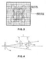
- Figure 3 illustrates contour lines in terms of intensity distribution of a focused spot, being deteriorated, in the scan end portion on the surface to be scanned.
- contour lines in Figure 3 depict intensities having been sliced with respect to the levels of (from the outside) 0.02, 0.05, 0.1, 0.1353, 0.3679, 0.5, 0.75 and 0.9, respectively, with the peak intensity of the focused spot being standardized to 1.
- the lateral direction corresponds to the main scan direction along which the focused spot scans
- the longitudinal direction corresponds to the sub-scan direction which is orthogonal to the main scan direction.
- the optical axis 71a of the first f- ⁇ lens 71 is disposed with an upward angle of 2 degrees so that it coincides with the principal ray of the light beam deflectively reflected by the deflecting surface 6a toward the scan center on the surface to be scanned. Namely, about the axis of the main scan direction, it is upwardly and rotatinally shifted by 2 deg. (2°) in the sub-scan section and with respect to the normal of the deflecting surface 6a.
- the optical axis 72a of the second f- ⁇ lens 72 is disposed with a downward tilt of an angle 1.83383, in the opposite direction to the first f- ⁇ lens 71, in the sub-scan section and with respect to a plane which is orthogonal to the rotational axis of the deflecting surface 6a. Namely, about the axis of the main scan direction, it is downwardly and rotatinally shifted by 1.83383 deg. in the sub-scan section and with respect to the normal to the deflecting surface 6a.
- the second f- ⁇ lens 72 is disposed with a shift of a predetermined amount in the sub-scan direction, so as to make it sure that the light beam is incident at a position above the plane vertex 72b, in the sub-scan section, of the first surface (light entrance surface) of the second f- ⁇ lens 72.
- curvature of scan lines on the photosensitive drum in the sub-scan direction as well as deterioratioin of focused spots at the scan end portion on the surface to be scanned are both well corrected.
- the optical deflector 6 comprises a resonance type optical deflector, having its deflecting surface 6a configured to perform reciprocating sine motion based on resonance.
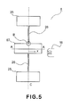
- Figure 5 shows details of the optical deflector 6 in this sembodiment.
- the optical deflector 6 comrises a movable plate 67 and a torsion spring 26 for resiliently supporting the movable plate 67 and mechanical ground suppots 25. All of these components are tosionally oscillated by driving means 16 around a tosional axis C (an axis parallel to the sub-scan direction).
- the driving means 16 may comprise a fixed electromagnet coil and a movable magnet mounted on the movable plate 67, for example.
- the movable plate 67 is provided with a deflecting surface (not shown) for deflecting the light beam, and the light beam from the light source means 1 is deflectively scanned on the basis of the torsional oscillation of the movable plate 67.
- the deflecting surface thereof receives large angular acceleration since it is torsionnally oscillated within a particular angle. Hence, during the drive, an inertia force due to the dead weight thereof is applied to the deflecting surface such that the deflecting surface would be distorted largely.
- Figure 6A is a sectional view, taken along a line A-A in Figure 5 , of the movable plate 67 in a case where it comprises a flat plate (rectangular parallelopiped).
- the optical deflector 6 of this embodiment is driven near the resonance frequency and is torsionally oscillated. Hence, the deflection angle of the movable plate 67 with respect to time changes sinusoidally. Thus, at the moment whereat a largest angluar speed is applied (e.g., largest deflection angle in the case of sine oscillation), largest deformatoin occurs.
- Figure 6B shows deformation of the movable plate 67 at that moment. It is seen from Figure 6B that, if the movable plate 67 deforms, the deflecting surface 6a formed on the movable plate 67 is deformed similarly.
- the movable plate 67 comprises a rectangular parallelopiped
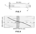
- deformation of the movable plate 67 during torsional oscillation can be explained by using an approximation model shown in Figure 7 .
- FIG. 7 The illustration made in Figure 7 corresonds specifically to the right-hand half of the sectional view of the movable plate 67 in Figure 6A .
- the deformation of the movable plate 67 is point-symmetrical about the torsional axis C, and it can be approximated as a deformation of a structural beam having its central portion fixed-end supported as illustrated in the drawing.
- Equation (1) 12 ⁇ ⁇ ⁇ 2 ⁇ ⁇ f 2 ⁇ ⁇ ⁇ W h 5 Et 2 ⁇ x 5 120 - x 3 12 + x 2 6
- the optical deflector 6 of this embodiment is arranged so that the natural oscillation frequency of the torsional oscillation is 2 KHz, the width (the value of aforementioned W) of the movable plate 67 in the main scan direction is 3 mm, the width thereof in the sub-scan direction is 1 mm, and the thickness t is 200 ⁇ m.
- the movable plate 67 recives an inertia force due to the dead weight thereof during the oscillation, and it is deformed thereby.
- Figure 8 is a graph showing the result of calculation made to the deformation of the movable plate 67 in accordance with the finite element method. It shows deformatoin of the A-A section in Figure 5 in a case where the mechanical effective deflection angle during 2 KHz driving is +22.5 degrees.
- the tilt of connection between the torsion spring 26 and the movable plate 67 was taken as zero.
- the scan angle can be specified as an angle defined in the main scan section and between the optical axis of the imaging optical system 7 and the principal ray of the light beam deflectively scanned by the deflecting surface of the optical deflector 6. Hence, the scan angle is twice the deflection angle (oscillation angle).
- the deflection angle at the scan-line-writing-start-position side on the surface to be scanned (upper in the sheet of Figure 1 and on the opposite side of the input optical system LA) has a positive (+) sign.
- the deflection angle at the scan-line-writing-end-position side on the surface to be scanned (lower in the sheet of Figure 1 and at the input optical system LA side) has a negative (-) sign.
- the direction of positive sign of y in Figure 8 corresponds to the advancement direction (rightward direction in the drawing) of the light beam reflected by the deflecting surface 6a in Figure 1
- the direction of positive sign of x corresponds to the scan-line-writing-start-position side of the deflecting surface 6a in Figure 1 (upper in the sheet of Figure 1 and on the opposite side of the input optical system LA).
- Figure 9 is a graph showing deformation of the A-A section in Figure 5 , wherein the tilt at the origin in the graph of Figure 8 is taken as zero. It is seen in Figure 9 that a deformation analogous to the deformation y given by Equation (1) above was obtained, and that the movable plate 67 was deformed by torsional oscillation.
- the deflecting surface 6a of the optical deflector 6 is being deformed such as shown in Figure 9 , the light beam reflected by the deflecting surface 6a would have wavefront aberration of an amount twice the deformation y shown in Figure 9 . Hence, an adverse influence would be exerted to the focused spot on the photosensitive drum surface 8.
- Figure 10 shows an example wherein an imaging lens having been designed to be used with a rotational polygonal mirror is used and, on the other hand, an optical deflector according to this embodiment (natural oscillation frequency of the torsion oscillation is 2 KHz, the width W of the movable plate in the main scan direction is 3 mm, the width thereof in the sub-scan diretion is 1 mm, and the thickness t is 200 ⁇ m) is used as an optical deflector.
- natural oscillation frequency of the torsion oscillation is 2 KHz
- the width W of the movable plate in the main scan direction is 3 mm
- the width thereof in the sub-scan diretion is 1 mm
- the thickness t is 200 ⁇ m
- Figure 10 illustrates the shapes of spots on the photosensitive drum 8 surface where the mechanical deflection angle is +22.5 degrees, +21.028 degrees, +16.822 degrees, +12.617 degrees, +8.411 degrees, +4.206 degrees and 0.0 degree, respectively.
- contours of the intensity distribution of each spot are illustrated there. These contours correspond to the intensities being sliced with respect to the levels of (from the outside) 0.02, 0.05, 0.1, 0.1353, 0.3679, 0.5, 0.75 and 0.9, respectively, when the peak intensity of the focused spot is standardized to 1.
- Figure 11 shows shapes of spots on the photosensitive drum surface 8 in a case where the same imaging lens is used and the deflecting surface 6a is not deformed at all.
- the lateral direction corresponds to the main scan direction along which the spot scans the surface
- the longitudinal direction corresponds to the sub-scan direction which is orthogonal to the main-scan direction.
- the spot shapes in Figure 10 where the deflecting surface 6a is being deformed include a large sidelobe in the main scan direction, as compared with the shapes of the focused spots shown in Figure 11 where the deflecting surface 6a is not deformed at all.
- the outer configuration itself of the focused spot is distorted asymmetrically, and the shape of the focused spot is deteriorated seriously. Furthermore, in the case of effective deflection angle +22.5 degrees, the peak intensity of the sidelobe exceeds 0.05 (namely, 5% of the peak intensity of the main spot).
- the effective deflection angle of the deflecting surface corresponding to the end portion (largest image height) of the scan line inside the effective image region on the surface to be scanned is made equal to ⁇ 22.5 degrees.
- the effective deflection angle of the deflecting surface should preferably be made not greater than ⁇ 30 degrees.
- the first and second f- ⁇ lenses 71 and 72 of this embodiment shown in Figure 1 are configured to reduce the amount of wavefront aberation produced by the deflection surface 6a, being distorted as shown in Figure 9 due to application of large angular acceleration thereto as a result of its sine oscillation.
- first direction is now used to refer to the direction of the phase difference of wavefront aberration in the main scan direction between a marginal ray and a principal ray of the light beam reflected by the deflecting surface 6a at an effective deflection angle of the same, the phase difference being produced as a result of reflection of the light beam by that deflecting surface.
- second direction is used to refer to the direction of the phase difference of wavefront aberration in the main scan direction between a marginal ray and a principal ray of the light beam reflected by the deflecting surface 6a at an effective deflection angle thereof, the phase difference being produced as a result of transmission of the light beam through the imaging optical system 7.
- At least one optical system inside the imaging optical system 7 is provided with at least one optical surface having non-arculate shape in the main scan section, so as to assure that the first and second directions mentioned above are made opposite to each other.
- the words "light beam reflected by the deflecting surface at an effective deflection angle thereof" refer to a light beam that reaches the scan end portion (largest image height) of the scan line inside the effective image region on the surface to be scanned.
- Figure 12 is a schematic view, showing the shape W1 of the wavefront (equi-phase plane) in the main scan direction, of the light beam after an inputted parallel light beam (plane wave) is reflected by the distorted deflecting surface 6a as shown in Figure 9 .
- the direction y in Figure 12 corresponds to the direction of displacement amount y which is taken on the axis of ordinates in the graph of Figure 9 .
- the state of advancement of the light beam being reflected in the positive (+) direction of the displacement amount y is illustrated there.
- the positive (+) direction along the x direction in Figure 12 corresponds to the positive (+) direction along the x axis of the graph of Figure 9 .
- the shape of the wavefront (equi-phase plane) of the light beam in the main scan direction after it is reflected by the distorted deflection surface 6a is being deformed by an amount twice the distorted shape of the deflection surface 6a.
- differences ⁇ L1 + and ⁇ L1 - are produced in the optical path length at the light beam end portions (marginal rays) in the main scan direction (x direction in Figure 12 ), with respect to that of the light beam central portion (principal ray of the light beam).
- ⁇ L1 + refers to the optical path difference at the positive (upper) side in the main scan direction
- ⁇ L1_ refers to the optical path difference at the negative (lower) side in the main scan direction.
- the marginal ray at the positive (upper) side in the main scan direction can be defined as a marginal ray at the scan-line-wrting-start-position side (upper in Figure 3 and opposite to the input optical system LA) with respect to the principal ray of the light beam.
- the marginal ray at the negative (lower) side in the main scan direction can be defined as a marginal ray at the scan-line-writing-end-position side (lower in Figure 1 and at the input optical system LA side).
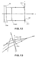
- Figure 13 is a schematic view, showing the shape of the wavefront (plane wave) after a parallel light beam (plane wave) passes through the f- ⁇ lens system 7, in a case where the effective deflection angle of the deflecting surface 6a is +22.5 degrees (at the scan-line-writing-start-position side). If the f- ⁇ lens system 7 is an idealistic lens having no aberration, the wavefront (equi-phase plane) after passing through the f- ⁇ lens system 7 forms a spherical wave S (solid line).
- the wavefront (equi-phase plane) after passing through the f- ⁇ lens system 7 is shaped such as shown at W2 in Figure 13 (broken line); that is, differences ⁇ L2 + and ⁇ L2 - are produced in the optical path length of the light beam end portions (marginal rays) in the main scan direction (x direction in Figure 13 ), relative to the light beam centeral portion (principal ray of the light beam).
- ⁇ L2 + refers to the optical path difference at the positive (upper) side (+x direction in Figure 12 ) in the main scan direction
- ⁇ L2_ refers to the optical path difference at the negative (lower) side (-x direction in Figure 12 ) in the main scan direction.
- the wavefront (equi-phase plane) of the light beam in the main scan direction being reflected by the distorted deflecting surface 6a as shown in Figure 12 is reduced.
- the wavefront aberration produced by the distorted deflecting surface 6a is corrected when the same passes through the f- ⁇ lens system 7.
- Figure 14 shows the shapes of focused spots on the photosensitive drum surface 8 according to this embodiment of the present invention.
- the wavefront aberration produced by the deflecting surface 6a being distorted by large angular acceleration applied thereto in response to sine oscillation is reduced by means of the f- ⁇ lens system 7.
- the sidelobes have been diminished and the outer configuration of the focused spots itself has been improved.
- the sidelobe having 5% peak intensity as shown in Figure 9 has been corrected completely.
- Figure 15 is a graph, showing wavefront aberration (here, differences of an actual wavefront having been influenced by the deformation, with respect to an idealistic plane wave) being produced by deformation of the deflecting surface 6a at an effective deflection angle +22.5 deg. of the same, in this embodiment.
- the axis of abscissa of the graph corresponds to the pupil coordinates, in the main scan direction, at the entrance pupil position of the optical system, wherein the pupil diameter 1.2 mm has been standardized to 1.
- the axis of ordinates denotes the amount of wavefront aberration, and the unit is ⁇ (780 nm).
- the direction of the wavefront aberration the direction of any delay of the actual wavefront relative to the idealistic wavefront with respect to the wavefront advancement direction is taken as negative (-).
- Figure 16 is a graph, showing wavefront aberration (differences of the actual wavefront to the spherical wave S described hereinbefore) being produced after a parallel light beam (plane wave) passes through the f- ⁇ lens system 7 where the effective deflection angle is +22.5 deg. in this embodiment.
- the axis of abscissa of the graph corresponds to the pupil coordinates, in the main scan direction, at the entrance pupil position of the optical system, wherein the pupil diameter 1.2 mm has been standardized to 1.
- the axis of ordinates denotes the amount of wavefront aberration, and the unit is ⁇ (780 nm).
- the direction of the wavefront aberration the direction of any delay of the actual wavefront relative to the idealistic wavefront with respect to the wavefront advancement direction is taken as negative (-).
- the f- ⁇ lens system 7 of this embodiment is configured to positively produce a wavefront aberration of the same amount as the wavefront aberration produced by the deformation of the deflecting surface 6a shown in Figure 15 , and in the oppoisite direction (cancelling direction).
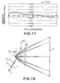
- Figure 17 is a graph, showing wavefront aberration (differences of the actual wavefront to the spherical wave S described hereinbefore) being produced after a light beam having wavefront aberration produced as a result of deformation of the deflecting surface 6a passes through the f- ⁇ lens system 7.
- the axis of abscissa of the graph corresponds to the pupil coordinates, in the main scan direction, at the entrance pupil position of the optical system, wherein the pupil diameter 1.2 mm has been standardized to 1.
- the axis of ordinates denotes the amount of wavefront aberration, and the unit is A (780 nm).
- the direction of any delay of the actual wavefront relative to the idealistic wavefront with respect to the wavefront advancement direction is taken as negative (-).
- a first wavefront aberration produced as a result of deformation of the deflecting surface 6a of the optical deflector 6 based on sine oscillation is compensated by positively producing, through the f- ⁇ lens system 7, a wavefront aberration of the same amount as the first wavefront aberration and in the opposite direction thereto.
- ⁇ L1 + is used to refer to the optical path difference between one of marginal rays (upper light ray) and the principal ray of the light beam reflected by the deflecting surface at an effective deflection angle +22.5 deg. thereof, the difference being produed as a result of reflection of the light beam by the deflecting surface.
- ⁇ L1 - is used to refer to the optical path difference between the other marginal ray (lower light ray) and the principal ray of the light beam reflected by the deflecting surface at an effective deflection angle +22.5 deg. thereof, the difference being produed as a result of reflection of the light beam by the deflecting surface.
- ⁇ L2 + is used to refer to the optical path difference between one of marginal rays (upper light ray) and the principal ray of the light beam reflected by the deflecting surface at an effective deflection angle +22.5 deg. of the same, the difference being produed as a result of transmission of the light beam through the imaging optical system.
- ⁇ L2 - is used to refer to the optical path difference between the other marginal ray (lower light ray) and the principal ray of the light beam reflected by the deflecting surface at an effective deflection angle +22.5 deg. of the same, the difference being produed as a result of transmission of the light beam through the imaging optical system.
- the imaging optical system satisfies the following relation. 0.8 ⁇ ⁇ L ⁇ 2 - - ⁇ L ⁇ 2 + ⁇ L ⁇ 1 + - ⁇ L ⁇ 1 - ⁇ 1.2
- Equation (4) can still be satisfied where the effective deflection angle of the deflecting surface is -22.5 deg. Furthermore, it should be noted that in this embodiment Equation (4) is satisfied with all deflection angles which are within the effective deflection angle range of ⁇ 22.5 degrees.
- the words "light beam reflected by the deflecting surface at an effective deflection angle thereof" refer to a light beam that reaches the scan end portion (largest image height) of the scan line inside the effective image region on the surface to be scanned.
- optical scanning systems or image forming apparatuses are accomplished by which high speed scan is attainable while using an optical deflector 6 based on sine oscillation and by which deterioration of image quality is reduced or avoided and high quality image outputs can be produced.
- Table 1-1 and Table 1-2 below show specifications of an optical system of an optical scanning system according to this embodiment of the present invention.
- TABLE 1-1 Used Reference Wavelength ⁇ (nm) 780 No. of Light Emission Points n 1 Position of Light Emission Points x0(mm) -29.38709 y0(mm) -75.99937 z0(mm) -3.57057 Semiconductor Laser Cover Glass Refractive Index n0 1.51072 Semiconductor Laser Cover Glass Thickness deg(mm) 0.25 Position of Stop x1(mm) -17.80914 y1(mm) -55.94578 z1(mm) -2.76195 Shape of Stop Elliptical Main-scan 2.4mm x Sub-scan 1.72mm Light Emission Point to Collimator Lens 1st Surface Distance d0(mm) 23.67000 Collimator Lens 1st Surface Position x2(mm) -17.55930 y2(mm) -55.51303 z2
- the point of intersection between each lens surface and the optical axis is taken as an origin.
- the optical axis direction is taken as an X axis
- the axis in the main scan section and being orthogonal to the optical axis is taken as a Y axis
- an axis in the sub-scan section and being orthogonal to the optical axis is taken as a Z axis.
- dX/dY (out)j is the tilt, in the main scan section, of the scan end portion with respect to the optical axis of the optical surface at the position where an outer scan marginal ray of the light beam, impinging on the largest scan position in the effective scan region on the surface to be scanned, passes through the j-th surface
- dX/dY (in)j is the tilt, in the main scan section, of the scan central portion with respect to the optical axis of the optic.al surface at the position where an inner scan marginal ray of the light beam, impinging on the largest scan position in the effective scan region on the surface to be scanned, passes through the j-th surface
- dX/dY (p)j is the tilt, in the main scan section, with respect to the optical axis of the optical surface at the position where the principal ray of the light beam, impinging on the largest scan position in the effective scan region on the surface to be scanned, passes through the j-th surface.
- Conditional equation (8) mentioned above represents the correlation between (i) the asymmetrical component of the wavefront aberration to the principal ray, exerted to the light beam impinging on the largest scan position in the effective scan region on the surface to be scanned, when that light beam passes through the f- ⁇ lens system 7, and (ii) the surface shape of each surface of the f- ⁇ lens system 7.
- the f- ⁇ lens system 7 of this embodiment is configured to positively produce a wavefront aberration of the same amount as the wavefront aberration produced by the deformation of the deflecting surface 6a, and in the oppoisite direction (cancelling direction).
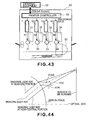
- Figure 44 illustrates a principal ray and a marginal ray that reach the largest scan position in the effective scan region on the surface to be scanned (here, in the case of Y>0) and an arbitrary lens surface of the f- ⁇ lens system 7 (here, the last surface, as an example).
- an angular difference should be present, in the main scan section, between (i) the angle defined by the marginal ray and the principal ray at the scan end portion side emerging from the lens surface and (ii) the angle defined by the marginal ray and the principal ray at the scan central portion side.
- both the marginal ray at the scan end portion side and the marginal ray at the scan central portion side have to reach the scan central portion side.
- ⁇ (out) is used to refer to the angle defined, in the main scan section, between (i) a marginal ray at the scan end portion side of the light beam passed through the lens surface and impinging on the largest scan position (here, Y>0) of the effective scan region on the surface to be scanned and (ii) the optical axis of the f- ⁇ lens system 7.
- ⁇ (in) is used to refer to the angle defined, in the main scan section, between (i) a marginal ray at the scan central portion side of the light beam passed through the lens surface and impinging on the largest scan position (here, Y>0) of the effective scan region on the surface to be scanned and (ii) the optical axis of the f- ⁇ lens system 7.
- ⁇ (p) is used to refer to the angle defined, in the main scan section, between (i) the principal ray of the light beam passed through the lens surface and impinging on the largest scan position (here, Y>0) of the effective scan region on the surface to be scanned and (ii) the optical axis of the f- ⁇ lens system 7. Then, the following condition is satisfied.
- dx/dy (out) is used to refer to the tilt, in the main scan section, of the lens surface with respect to the optical axis of the f- ⁇ lens system 7 at the position where a scan end portion side marginal ray of the light beam, impinging on the largest scan position (here, Y>0) in the effective scan region on the surface to be scanned, passes through the lens surface.
- dx/dy (in) is used to refer to the tilt, in the main scan section, of the lens surface with respect to the optical axis of the f- ⁇ lens system 7 at the position where a scan central portion side marginal ray of the light beam, impinging on the largest scan position (here, Y>0) in the effective scan region on the surface to be scanned, passes through the lens surface.
- dx/dy(p) is used to refer to the tilt, in the main scan section, of the lens surface with respect to the optical axis of the f- ⁇ lens system 7 at the position where the principal ray of the light beam, impinging on the largest scan position (here, Y>0) in the effective scan region on the surface to be scanned, passes through the lens surface.
- the refractive index of the light entrance side of the lens surface is denoted by N
- the refractive index of the light exit side of the lens surface is denoted by 1.
- Equation (9) mentioned above can be rewritten as N - 1 ⁇ d x d y out + d x d y in + 2 ⁇ d x d y p > 0
- Table 1-3 and Table 1-4 below show numerical values in this embodiment as well as numerical values of the left side of Equation (11) above.
- TABLE 1-3 Y>0 1st Surface 2nd Surface 3rd Surface 4th Surface Scan End Side Marginal Ray Passage Y Coordinate 23.5078 25.5376 43.6122 45.4727 Principal Ray Passage Y Coordinate 21.9026 24.1839 42.1086 44.0691 Scan Central Side Marginal Ray Passage Y Coordinate 20.3084 22.8352 40.5895 42.6369 dx/dy (out) -0.10503 -0.38188 -0.13347 -0.40257 dx/dy (up) -0.12708 -0.40728 -0.09675 -0.33802 dx/dy (in) -0.14383 -0.42204 -0.06310 -0.28078 U -1 1 -1 -1 N 1.52420 1.52420 1.52420 1.52420 U(N-1)(dx/dy
- Equation (11) the value of the left side of Equation (11) is positive when Y>0, and it is negative when Y ⁇ 0, such that Equation (11) is surely satisfied.
- Equation (11) is satisfied to thereby positively produce a wavefront aberration of the same amount as the wavefront aberration produced by the deformation of the deflecting surface 6a as shown in Figure 16 , and in the oppoisite direction (cancelling direction).
- the wavefront aberration produced as a result of deformation of the deflecting surface 6a is effectively reduced, and high-quality image output is accomplished.
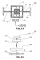
- Figure 18 illustrates a section (main scan section) of a main portion of a second embodiment of the present invention, in the main scan direction.
- elements corresponding to those shown in Figure 1 are denoted by like numerals.
- This embodiment differs from the first embodiment in that an optical deflector 166 having a structure different from that of the optical deflector 6 of the first embodiment is used as the deflecting means.
- first and second imaging lenses (f- ⁇ lenses) 161 and 162 that constitute an f- ⁇ lens system 167 have different shapes. The remaining portions have a similar structure and optical function as of the first embodiment, and similar advantageous results are provided.
- FIG 18 denoted at 166 is an optical deflector (deflecting means), and it has a structure such a shown in Figure 19 .
- the optical deflector 166 comprises a plurality of movable plates 171 and 172 and a plurality of torsion springs 173 and 174 which are formed integrally out of a single plate, wherein the torsion springs 173 and 174 are fixed to support members 175 and 176, respectively.
- the optical deflector 166 has a deflecting surface which is formed on one (171) of the plural movable plates.
- the torsion springs 173 and 174 are disposed rectilinearly along one and the same axis.
- these movable plates 171 and 172 can be swingingly moved about the torsional axis of the torsion springs 173 and 174 (i.e., an axis parallel to the sub-scan direction).
- a deflecting surface (not shown) is provided on the movable plate 171, for deflectively scanning a light beam. Through the torsional oscillation of the movable plate 171, the light beam from the light source means can be deflectively scanned in the main scan direction.
- Figure 20 is a schematic view for explaining the principle of the optical deflector 166.
- denoted at 1801 - 1803 are movable plates of a number n.
- Denoted at 1811 - 1813 are torsion springs of a number n, and denoted at 1821 is a support.
- the torsion springs 1811 - 1813 are disposed along a straight line, and the movable plates 1801 - 1803 are arranged to be swingingly moved around the torsional axis of the springs 1811 - 1813.
- a reference frequency and a frequency or frequencies corresponding to a multiple, by an integral number, of the reference frequency are included in the angular frequency ⁇ k of the natural mode.
- the reciprocating motion of the deflecting surface of the optical deflector of this embodiment has a plurality of discrete natural oscillation modes.
- a reference oscillation mode which is a natural oscillation mode at the reference frequency as well as an integral-number-multiple oscillation mode which is a natural oscillation mode at a frequency corresponding to a multiple, by an integral number of not less than 2, of the reference frequency are included.
- the optical deflector 166 shown in Figure 21 comprises two movable plates 1901 and 1902, and two torsion springs 1911 and 1912 for coupling the two movable plates 1901 and 1902 in series and being disposed along one and the same axis.
- a support 1921 for supporting a portion of the two torsion springs 1911 and 1912.
- driving means 1941 for applying a torque to at least one of the two movable plates 1901 and 1902, and drive control means 1951 for controlling the driving means 1941.
- ⁇ 2 2 ⁇ 1 .
- these oscillation modes will be referred to as “Mode 1” (reference oscillation mode) and “Mode 2” (integral-number-multiple oscillation mode).
- the drive control means 1951 controls the driving means 1941 so that the system constituted by two movable plates 1901 and 1902 and two torsion springs 1911 and 1912 can be oscillated at the reference frequency and a frequency corresponding to a multiple thereof by an integral number, at the same time.
- the amplitude and phase of the movable plates at the reference frequency and a frequency corresponding to a multiple thereof by an integral number may be changed in various ways, by which the driving can be done in various manners.
- the drive control means 1951 controls the driving means 1941 so as to set the following conditions. That is, in Figure 19 :
- the size of the movable plate 171 is 3.0 mm in the longitudinal direction in Figure 19 (main scan direction) and it is 2.0 mm in the lateral direction (sub-scan direction).
- the movable plate 171 is provided with a deflecting surface (not shown), such that the light beam from the semiconductor laser 1 is deflectively scanned at an angle 2 ⁇ 1 , that is, twice the angle of Equation (15) above.
- Figure 22 is a graph for explaining the oscillation angle (deflection angle) ⁇ 1 of the movable plate 171 of the optical deflector 166 of this embodiment.
- the axis of abscissa denotes the period (time)
- the axis of ordinates denotes the oscillation angle (deflection angle) ⁇ 1 wherein the unit is deg.
- the optical deflector 6 comprises a deflector which is based on sine oscillation and an f- ⁇ lens is used as an imaging lens to be combined with this deflector.
- an f- ⁇ lens is used simply as an imaging lens in combination with a sine-oscillation optical deflector, it raises a problem that, as compared with the scan central portion on the photosensitive drum surface 8, the scan speed at the scan end portion on the photosensitive drum surface 8 becomes slower to cause contraction of an image in the main scan direction.
- the modulation clock of the semiconductor laser 1 is changed continuously in synchronism with the scan position, in the main scan direction, on the photosensitive drum surface 8, by which the above-described inconvenience is avoided.
- the above-described Mode 1 and Mode 2 are excited simultaneously by which, as compared with normal sine oscillation, there is produced a region in which the oscillation angle (deflection angle) ⁇ 1 is nearly proportional to time (namely, the region in which the oscillation angle can be regarded as being proportional to time).
- an ordinary f- ⁇ lens may be used as an imaging lens to be combined therewith, by which, on the photosensitive drum surface 8, nearly uniform speed scan can be accomplished.
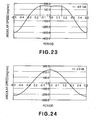
- Figure 23 is a graph for explaining the angular speed d ⁇ 1 /dt of the movable plate 171 of the optical deflector of this embodiment.
- the angular speed d ⁇ 1 /dt at the scan center (period is 0) is 160.0 (deg/sec), and the angular speed increases as the scan position comes close to the scan end portion.
- the angular speed d ⁇ 1 /dt becomes largest at the period ⁇ 0.098, and it takes a value 164.708 (deg/sec) at that time.
- the angular speed d ⁇ 1 /dt takes a value 160.0 (deg/sec).
- Figure 24 illustrates an example of angular speed d ⁇ /dt of a movable plate 171 which has only Mode 1.
- Figure 25 further shows an actual image height wherein a light beam which is being reflected and deflectively scanned, up to a period 0.14, by means of the deflecting surface 166a of the optical deflector 166 of this embodiment, having an angular speed d ⁇ 1 /dt, shown in Figure 23 , is scanned by the same f- ⁇ -lens.
- Figure 26 shows this difference as an f- ⁇ error.
- the deflector may be used in this state.
- the f- ⁇ error component shown in Figure 26 as produced by a deviation of the above-described angular speed d ⁇ 1 /dt from the uniform angular speed, is corrected by means of the f- ⁇ lens system 167.
- Figure 27 is a graph showing an f- ⁇ error in a case where the light beam reflected by the deflecting surface 166a having an angular speed d ⁇ 1 /dt shown in Figure 23 is scanned with the f- ⁇ lens system 167. It is seen that, as compared with Figure 26 , the f- ⁇ error is remarkably reduced.
- Figure 28 shows the angular acceleration d 2 ⁇ 1 /dt 2 of the movable plate 171 of the optical deflector 166 of this embodiment and, as a comparative example, Figure 29 shows the angular acceleration d 2 ⁇ /dt 2 of the movable plate 171 exited in Mode 1 only.
- the optical deflector 166 of this embodiment by exciting the above-described Mode 1 and Mode 2 simultaneously, as compared with normal sine oscillation, the angular acceleration d 2 ⁇ 1 /dt 2 of the movable plate 171 can be reduced significantly.
- the movable plate 171 may be deformed due to the angular acceleration during oscillation.
- the angular acceleration of the movable plate 171 in this embodiment is quite small as compared with the angular acceleration during simple sine oscillation, deformation of the movable plate 171 would be very small.
- Figure 30 is a graph, showing the result of calculation made to deformation of the movable plate 171 of this embodiment, in accordance with the finite element method.
- the width of the movable plate 171 in the main scan direction is 3 mm
- the width in the sub-scan direction is 1 mm.
- the thickness is 200 ⁇ m.
- the deformation amount is less than one-third.
- the deflecting surface 166a would be deformed similarly in response to the deformation of the movable plate 171, since that deformation would be about one-third as compared with the first embodiment, the wavefront aberration to be produced by the deflecting surface 166a would be about one-third of that in the first embodiment.
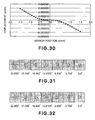
- Figure 31 shows an example wherein an f- ⁇ lens having been designed on an assumption that the deflecting surface 166a has no deformation is used, but actually the deflecting surface 166a is being deformed as described above.
- Figure 31 shows shapes of spots on the photosensitive drum surface 8 that correspond to the deflection angles, of the deflecting surface 166a, of +22.856 deg. (corresponding to the period 0.14), +21.599 deg., +16.485 deg., +12.628 deg., +8.800 deg., +3.754 deg. and 0.0 deg.
- Figure 31 illustrates contours of the intensity distribution of each spot, similar to Figure 14 .
- the contour lins in Figure 31 depict intensities having been sliced with respect to the levels of (from the outside) 0.02, 0.05, 0.1, 0.1353, 0.3679, 0.5, 0.75 and 0.9, respectively, with the peak intensity of the focused spot being standardized to 1.
- the peak intensity of the sidelobe does not exceed 0.05 (i.e., 5% of the peak intensity of the main focused spot), it would not cause serious image deterioration.
- the spot shapes at the deflection angles of +22.856 deg. and +21.599 deg. are not so good.
- the amount of wavefront aberration produced as a result of deformation of the deflecting surface 166a is corrected by means of the f- ⁇ lens system 167.
- ⁇ L1 + is used to refer to the optical path difference between one of marginal rays (upper light ray) and the principal ray of the light beam reflected by the deflecting surface at an effective deflection angle +22.85 deg. thereof, the difference being produed as a result of reflection of the light beam by the deflecting surface.
- ⁇ L1 - is used to refer to the optical path difference between the other marginal ray (lower light ray) and the principal ray of the light beam reflected by the deflecting surface at an effective deflection angle +22.85 deg. thereof, the difference being produed as a result of reflection of the light beam by the deflecting surface.
- ⁇ L2 + is used to refer to the optical path difference between one of marginal rays (upper light ray) and the principal ray of the light beam reflected by the deflecting surface at an effective deflection angle +22.85 deg. of the same, the difference being produed as a result of transmission of the light beam through the imaging optical system.
- the marginal ray at the positive (upper) side with respect to the main scan direction refers to a light ray which is at the scan-line-writing-start-position side (upper in the sheet of Figure 19 and on the opposite side of the input optical system LA) on the surface to be scanned with respect to the principal ray of the light beam.
- the marginal ray at the negative (lower) side with respect to the main scan direction refers to a light ray which is at the scan-line-writing-end-position side (lower in the sheet of Figure 19 and the input optical system LA side) on the surface to be scanned with respect to the principal ray of the light beam.
- ⁇ L2 - is used to refer to the optical path difference between the other marginal ray (lower light ray) and the principal ray of the light beam reflected by the deflecting surface at an effective deflection angle +22.85 deg. of the same, the difference being produed as a result of transmission of the light beam through the imaging optical system.
- the imaging optical system satisfies the following relation. 0.8 ⁇ ⁇ L ⁇ 2 - - ⁇ L ⁇ 2 + ⁇ L ⁇ 1 + - ⁇ L ⁇ 1 - ⁇ 1.2
- Equation (18) can still be satisfied where the effective deflection angle of the deflecting surface is -22.85 deg. Furthermore, it should be noted that in this embodiment Equation (18) is satisfied with all deflection angles which are within the effective deflection angle range of ⁇ 22.85 degrees.
- the words "light beam reflected by the deflecting surface at an effective deflection angle thereof" refer to a light beam that reaches the scan end portion (largest image height) of the scan line inside the effective image region on the surface to be scanned.
- Figure 32 shows shapes of spots on the photosensitive drum surface 8 in this embodiment. As compared with Figure 31 , it is seen that sidelobes of the focused spots, particularly those at the deflection angles of +22.856 deg. and +21.599 deg. have been corrected satisfactorily.
- the angular speed d ⁇ 1 /dt of the movable plate 171 of the optical deflector 166 in this embodiment is constant in the range of periods ⁇ 0.14. However, it is not yet completely constant.
- the error component is corrected by means of the f- ⁇ lens system 167.
- the light beam not deflected at uniform angular speed is corrected so that it moves at uniform speed on the photosensitive drum surface 8, the spot diameter in the main scan direction would change.
- Such change in the spot diameter in the main scan direction on the surface to be scanned is inversely proportional to the angular speed d ⁇ 1 /dt of the movable plate 171 of the optical deflector 166.
- the largest oscillation amplitudes ⁇ 1 and ⁇ 2 of the movable plate 171 in the Mode 1 and Mode 2 as well as the angular frequencies ⁇ 1 and ⁇ 2 thereof, the phase differences, and so on, are chosen optimally. Then, by setting the change in angular speed inside the effective scan region smallest, the change in spot diameter in the main scan direction can be reduced to a lowest level.
- the change in angular speed in the effective scan region is made small as shown in Figure 23 .
- the change in spot diameter in the main scan direction can be made small.
- the largest oscillation amplitudes ⁇ 1 and ⁇ 2 of the movable plate 171 in the Mode 1 and Mode 2 as well as the angular frequencies ⁇ 1 and ⁇ 2 thereof, the phase differences, and so on, should preferably be chosen optimally, to assure that the change in angular speed d ⁇ 1 /dt of the movable plate 171 of the optical deflector 166 is suppressed to 10% or less within the effective scan region.
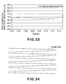
- Figure 33 shows the spot diameter in the main scan direction on the photosensitive drum surface 8 in this embodiment.
- ⁇ n 1 the largest value of spot diameter of the focused spot, in the main scan direction, inside the same scan line within the effective scan region on the surface 8 to be scanned
- ⁇ n 0 the smallest value of spot diameter of the focused spot, in the main scan direction, inside the same scan line within the effective scan region on the surface 8 to be scanned
- the following relation is satisfied: ⁇ ⁇ n 1 / ⁇ ⁇ n 0 ⁇ 1.1 More preferably, a relation ⁇ ⁇ n 1 / ⁇ ⁇ n 0 ⁇ 1.05 should be satisfied.
- the spot diameter of the focus spot in the main scan direction in this embodiment, changes from 67.27 ⁇ m to 69.17 ⁇ m, and thus the diameter change is kept approximately to 2.8%.
- optical scanning systems and image forming apparatuses which require high-quality image outputs can be accomplished.
- the optical scanning system of this embodiment uses an optical deflector having reciprocating motion, if an image is formed in both of the forward stroke and the backward stroke, the tilt of the scan line on the photosensitive drum surface 8 changes alternately as shown in Figure 34 . This results in unevenness of the pitch in the image end portion.
- the image formation may be carried out during the scan in one of the reciprocating strokes.
- a monolithic multiple-beam semiconductor laser or the like having plural light emission points (light emitting units) may preferably be used as the light source means.
- Table 2-1 and Table 2-2 below show specifications of the scanning optical system of this embodiment.
- TABLE 2-1 Used Reference Wavelength ⁇ (nm) 780 No. of Light Emission Points n 1 Position of Light Emission Points x0(mm) -29.38709 y0(mm) -75.99937 z0(mm) -3.57057 Semiconductor Laser Cover Glass Refractive Index n0 1.51072 Semiconductor Laser Cover Glass Thickness deg(mm) 0.25 Position of Stop x1(mm) -17.80914 y1(mm) -55.94578 z1(mm) -2.76195 Shape of Stop Elliptical Main-scan 2.4mm scan 1.72mm Light Emission Point to Collimator Lens 1st Surface Distance d0(mm) 23.67000 Collimator Lens 1st Surface Position x2(mm) -17.55930 y2(mm) -55.51303 z2(mm) -2.74450 Collimator Lens 2nd
- the point of intersection between each lens surface and the optical axis is taken as an origin.
- the optical axis direction is taken as an X axis
- the axis in the main scan section and being orthogonal to the optical axis is taken as a Y axis
- an axis in the sub-scan section and being orthogonal to the optical axis is taken as a Z axis.
- TABLE 2-3 Y>0 1st Surface 2nd Surface 3rd Surface 4th Surface Scan End Side Marginal Ray Passage Y Coordinate 23.8256 26.0248 44.5711 45.7894 Principal Ray Passage Y Coordinate 22.2286 24.6691 43.1176 44.5121 Scan Central Side Marginal Ray Passage Y Coordinate 20.6504 23.3226 41.6516 43.2030 dx/dy (out) -0.12743 -0.39364 -0.19294 -0.56148 dx/dy (up) -0.14644 -0.41363 -0.15573 -0.49107 dx/dy (in) -0.16058 -0.42475 -0.12032 -0.42688 U -1 1 -1 -1 N 1.52420 1.524
- Equation (24) the value of the left side of Equation (24) is positive when Y>0, and it is negative when Y ⁇ 0, such that Equation (24) is surely satisfied.
- Equation (24) is satisfied to thereby positively produce a wavefront aberration of the same amount as the wavefront aberration produced by the deformation of the deflecting surface 6a as shown in Figure 16 , and in the oppoisite direction (cancelling direction).
- the wavefront aberration produced as a result of deformation of the deflecting surface 6a is effectively reduced, and high-quality image output is accomplished.
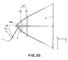
- Figure 35 illustrates a section (main scan section) of a main portion of a third embodiment of the present invention, in the main scan direction.
- elements corresponding to those shown in Figure 18 are denoted by like numerals.
- This embodiment differs from the second embodiment in that the input optical system LA is structured without a cylindrical lens 4.
- the shape of first and second imaging lenses (f- ⁇ lenses) 181 and 182 that constitute an f- ⁇ lens system 187 is designed while taking into account that deformation of the deflecting surface 166a in the main scan direction is changeable with the position of the deflecting surface 166a in the sub-scan direction.
- the optical deflector 166 based on reciprocating motion as in this embodiment has only one deflecting surface 166a and, therefore, there is no need of using a plane tilt correcting optical system.
- the deflecting surface 166a and the photosensitive drum surface 8 are in a conjugate relation with each other, with respect to the f- ⁇ lens 187. Namely, no plane tilt correcting optical system is used there. Furthermore, a cylindrical lens or the like is not disposed between the deflecting surface 166a and the light source means 1.
- optical deflector 166 of this embodiment The structure and the principle of the optical deflector 166 of this embodiment are such as described with reference to the second embodiment.
- the deflecting surface 166a of this optical deflector 166 is deformed in the main scan section (main scan direction) due to angular acceleration which results from the reciprocating motion, and the amount of this deformation is changeable in dependence upon the position of the deflecting surface 166a in the sub-scan direction.
- Figure 36 is a graph showing the result of calculation made to the deformation of the movable plate 171 of this embodiment, in accordance with the finite element method.
- Figure 36 shows deformation of the A-A section in Figure 19 (central portion in the sub-scan direction) at the period 0.14 (light ray scan angle of 45 deg.) when the movable plate 171 that constitute the optical deflector 166 is being resonance-driven in accordance with the aforementioned Equation (15).
- the tilt of connection (at C in Figure 19 ) between the torsion spring 173 and the movable plate 171 is taken as zero.
- the axis of abscissa denotes the position coordinates of the movable plate 171 (unit is ⁇ m), and the axis of ordinates denotes the deformation amount y of the movable plate 171 (unit is ⁇ m).
- Figure 37 is a graph showing the result of calculation made to deformation of the B-B section (the position spaced by 0.9 mm from the central portion in the sub-scan direction toward the sub-san direction) in Figure 19 , in accordance with the finite element method.
- the tilt of connection (at C in Figure 19 ) between the torsion spring 173 and the movable plate 171 is taken as zero.
- Figure 38 is a schematic and perspective view wherein the amount of deformation described above is illustrated three-dimensionally.
- the direction of the movable-plate position x in Figure 37 corresponds to the main scan direction, and the direction of the movable-plate position z corresponds to the sub-scan direction.
- the scan position where the deformation shown in Figure 38 is produced corresponds to the largest effective scan position at the side remote from the light source side in Figure 35 .
- the scan position where the deformation shown in Figure 38 is produced does correspond to the largest effective scan position at a side opposite to the light source means 1 side, with respect to the center of the optical axis of the imaging optical system 187, and it corresponds to deformation of the deflecting surface at the effective deflection angle of +22.5 deg.
- the deflecting surface 166a is being deformed into a concave shape, in the z-direction section (sub-scan section) and at the negative (-) side of the movable-plate position x, whereas, to the contrary, it is deformed into a convex shape in the z-direction section (sub-scan section) at the positive (+) side of the movable-plate position x.
- the deflecting surface 166a is deformed into a convex shape in the z-direction section (sub-scan section) at the negative (-) side of the movable-plate position x, whereas, to the contrary, it is deformed into a concave shape in the z-direction section at the positive (+) side of the movable-plate position x.
- the f- ⁇ lens 187 does not function to bring the deflecting surface 166a and the photosensitive drum surface 8 into a conjugate relationship with each other. Namely, no tilt correction optical system is provided. Therefore, the light beam incident on the deflecting surface 166a has a desired light beam width in each of the main scan direction and the sub-scan direction.
- a light beam being converged in the sub-scan direction is projected upon the deflecting surface.
- the light beam width in the sub-scan direction, upon the deflecting surface is generally about 0.1 mm or less.
- the light beam width upon the deflecting surface in the sub-scan direction if no tilt correction optical system is provided needs to be a light beam width as determined by the spot diameter on the photosensitive drum surface 8.
- the light beam width on the deflecting surface 166a is 2.4 mm in the main scan direction, and it is 1.72 mm in the sub-scan direction.
- the movable plate 171 is being deformed such as shown in Figures 36 - 38 due to the dead weight thereof.
- the deflecting surface 166a there is produced wavefront aberration of an amount twice the deformation y shown in Figures 36 - 38 .
- an adverse influence would be exerted to the focused spot on the photosensitive drum surface 8.
- Figure 39 shows an example of spot shapes on the photosensitive drum surface 8 in a case where an imaging lens having been designed on an assumption that the deflecting surface 166a has no deformation is used and where the deflecting surface 166a is actually being deformed as in this embodiment.
- Figure 39 illustrates the shapes of spots on the photosensitive drum 8 surface where the deflection angle of the light beam deflected by the deflecting surface 166a is +22.5 degrees, +21.028 degrees, 0 degree, -21.028 degree, -22.5 degree, respectively.
- Contours in Figure 39 correspond to the intensities being sliced with respect to the levels of (from the outside) 0.02, 0.05, 0.1, 0.1353, 0.3679, 0.5, 0.75 and 0.9, respectively, when the peak intensity of the focused spot is standardized to 1.
- the lateral direction corresponds to the main scan direction along which the spot scans the surface
- the longitudinal direction corresponds to the sub-scan direction which is orthogonal to the main-scan direction.
- the spot shapes in the case where the deflecting surface 166a is being deformed include a sidelobe in the main scan direction and obliquie directons.
- the outer configuration itself of the focused spot is distorted into a barrel-like shape, and the shape of the focused spot is deteriorated seriously.
- the f- ⁇ lens system 187 is configured to reduce the amount of wavefront aberration after being transmitted through the f- ⁇ lens 187, which aberration has been produced by the deflecting surface 166a being distorted as shown in Figures 36 - 38 due to the resonance drive.
- Figure 40 illustrates the shapes of spots formed on the photosensitive drum surface 8, in this embodiment of the present invention.
- the amount of wavefront aberration produced by the deflecting surface 166a being distorted by angular acceleration applied thereto in response to the resonance drive is reduced by means of the f- ⁇ lens system 187.
- the sidelobes haven been diminished and the outer configuration of the focused spots itself has been improved.
- first direction is now used to refer to the direction of the phase difference of wavefront aberration in the main scan direction between a marginal ray and a principal ray of the light beam reflected by the deflecting surface 166a at an effective deflection angle of the same, the phase difference being produced as a result of reflection of the light beam by that deflecting surface.
- first direction may refer to the direction of the optical path difference of the marginal ray in the main scan direction, with respect to the principal ray, of the light beam reflected by the deflecting surface 166a, the path length difference being produced as a result of reflection of the light beam by that deflecting surface.
- second direction is used to refer to the direction of the phase difference of wavefront aberration in the main scan direction between a marginal ray and a principal ray of the light beam reflected by the deflecting surface 166a at an effective deflection angle thereof, the phase difference being produced as a result of transmission of the light beam through the f- ⁇ lens system 187.
- second direction may refer to the direction of the direction of the optical path difference of the marginal ray in the main scan direction, with respect to the principal ray, of the light beam reflected by the deflecting surface 166a, the path length difference being produced as a result of transmission of that light beam through the imaging optical system.
- At least one optical element inside the f- ⁇ lens system 187 is provided with at least one optical surface having non-arculate shape in the main scan section, so as to assure that the first and second directions mentioned above are made opposite to each other.
- the optical principle for that is such as described with reference to the first embodiment (see Figures 12 - 17 ).
- the amount of wavefront aberration produced due to deformation of the deflecting surface 166a can be reduced significantly.
- the wavefront aberration produced as a result of deformation of the deflecting surface 166a of the optical deflector 166 based on sine oscillation is compensated by positively producing, through the f- ⁇ lens system 187, a wavefront aberration of the same amount as the wavefront aberration resulting from the deformation.
- ⁇ L1 + is used to refer to the optical path difference between one of marginal rays (upper light ray) and the principal ray of the light beam reflected by the deflecting surface at an effective deflection angle +22.5 deg. thereof, the difference being produed as a result of reflection of the light beam by the deflecting surface.
- ⁇ L1 - is used to refer to the optical path difference between the other marginal ray (lower light ray) and the principal ray of the light beam reflected by the deflecting surface at an effective deflection angle +22.5 deg. thereof, the difference being produced as a result of reflection of the light beam by the deflecting surface.
- ⁇ L2 + is used to refer to the optical path difference between one of marginal rays (upper light ray) and the principal ray of the light beam reflected by the deflecting surface at an effective deflection angle +22.5 deg. of the same, the difference being produed as a result of transmission of the light beam through the imaging optical system.
- 5L2- is used to refer to the optical path difference between the other marginal ray (lower light ray) and the principal ray of the light beam reflected by the deflecting surface at an effective deflection angle +22.5 deg. of the same, the difference being produed as a result of transmission of the light beam through the imaging optical system.
- the imaging optical system satisfies the following relation. 0.8 ⁇ ⁇ L ⁇ 2 - - ⁇ L ⁇ 2 + ⁇ L ⁇ 1 + - ⁇ L ⁇ 1 - ⁇ 1.2
- Equation (25) can still be satisfied where the effective deflection angle of the deflecting surface is -22.5 deg. Furthermore, it should be noted that in this embodiment Equation (25) is satisfied with all deflection angles which are within the effective deflection angle range of ⁇ 22.5 degrees.
- Figure 41 schematically illustrates the state of wavefront after a parallel light beam, having been incident at a scan position corresponding to the light beam, passed through the f- ⁇ lens system 187.
- the light beam incident on the f- ⁇ lens system 187 is parallel both in the main scan section and in the sub-scan section.
- the x axis in Figure 41 corresponds to the x axis in Figure 38
- the y axis in Figure 41 corresponds to the y axis of Figure 38
- the z axis in Figure 41 corresponds to the z axis of Figure 38 . This applies similarly to the x and y axes of Figure 35 .
- Figure 41 illustrates the wavefront of a parallel light beam in the sub-scan direction after the same passed through the f- ⁇ lens system 187, in a case where the sign of the deflection angle is positive.
- it illustrates the wavefront in the sub-scan direction after the light beam, impinging on a scan position between the scan center on the surface to be scanned and the writing-star-position-side largest effective scan position (largest image height) on the surface to be scanned, in the main scan section, passed through the f- ⁇ lens system 187.
- the scan center on the surface to be scanned and the writing-start-position side correspond to the upper side in Figure 35 as well as the side opposite to the input optical system LA.
- ro denotes the curvature radius of the wavefront in the sub-scan direction, at the position of a ray (principal ray) in the central portion with respect to the main scan direction, after the parallel light passed through the f- ⁇ lens system 187.
- ru similarly denotes the curvature radius of the wavefront in the sub-scan direction at the light ray position at the scan end portion side (positive side in the x direction) with respect to the principal ray in the main scan direction, after the parallel light passed through the f- ⁇ lens system 187.
- rl similarly denotes the curvature radius of the wavefront in the sub-scan direction at the light ray position at the scan central portion side (negative side in the x direction) with respect to the principal ray in the main scan direction, after the parallel light passed through the f- ⁇ lens system 187.
- the curvature radius ru of the wavefront in the sub-scan direction at the light ray passage position at the scan end portion side with respect to the principal ray of the light beam after the same passed through the f- ⁇ lens system 187 is set as follows.
- the curvature radius ru of the wavefront in the sub-scan direction at the light ray passage position at the scan end portion side with respect to the principal ray of the light beam is made larger than the curvature radius rl of the wavefront in the sub-scan direction at the light ray passage position at the scan central portion side with respect to the principal ray of the light beam, namely, rl ⁇ ru.
- scan end portion side refers to the positive side in the x direction
- scan central portion side refers to the negative side in the x direction
- the wavefront is deformed into a concave shape in the z-direction section (sub-scan section) at the negative side of the movable plate position x, as shown in Figure 38 . Furthermore, in the z-direction section (sub-scan section) at the positive side of the movable plate position x, it is deformed into a convex shape, to the contrary. As a result of these deformations, the produced wavefront aberration can be corrected effectively.
- the wavefront in the sub-scan direction after a parallel light passed through the f- ⁇ lens 187 in a case where the sign of the deflection angle is negative, is such as follows.
- the curvature radius ru' of the wavefront of the light beam in the sub-scan direction at the light ray passage position at the scan center side, with respect to the principal ray of the light beam is made smaller than the curvature radius rl' of the wavefront of the light beam in the sub-scan direction at the light ray passage position at the scan end portion side with respect to the principal ray of the light beam, namely, rl'>ru'.
- the wavefront in the sub-scan direction after the light beam, impinging on the scan position between the scan center on the surface to be scanned and the writing-star-position-side largest effective scan position (largest image height) on the surface to be scanned, in the main scan section, passes through the f- ⁇ lens system 187 satisfies the relation rl'>ru'.
- scan center side refers to the positive side in the x direction in Figure 41
- scan end portion side refers to the negative side in the x direction in Figure 41 .
- high-speed scan can be achieved even if an optical deflector 166 based on resonance drive is used, and optical scanning systems and image forming apparatuses which require high-quality image outputs without deteriorated image quality can be accomplished.
- Table 3-1 and Table 3-2 below show specifications of the scanning optical system according to this embodiment of the present invention.
- TABLE 3-1 Used Reference Wavelength ⁇ (nm) 780 No. of Light Emission Points n 1 Position of Light Emission Points x0(mm) -29.38709 y0(mm) -75.99937 z0(mm) -3.57057 Semiconductor Laser Cover Glass Refractive Index n1 1.51072 Semiconductor Laser Cover Glass Thickness deg(mm) 0.25 Position of Stop x1(mm) -17.80914 y1(mm) -55.94578 z1(mm) -2.76195 Shape of Stop Elliptical Main-scan 2.4mm x Sub-scan 1.72mm Light Emission Point to Collimator Lens,1st Surface Distance Surface Distance d1(mm) 23.67000 Collimator Lens 1st Surface Position x2(mm) -17.55930 y2(mm) -55.51303 z2(
- the point of intersection between each lens surface and the optical axis is taken as an origin.
- the optical axis direction is taken as an X axis
- the axis in the main scan section and being orthogonal to the optical axis is taken as a Y axis
- an axis in the sub-scan section and being orthogonal to the optical axis is taken as a Z axis.
- Table 3-3 and Table 3-4 below show numerical values in this embodiment as well as numerical values of the left side of Equation (29) above.
- Equation (29) the value of the left side of Equation (29) is positive when Y>0, and it is negative when Y ⁇ 0, such that Equation (29) is surely satisfied.
- Equation (29) is satisfied to thereby positively produce a wavefront aberration of the same amount as the wavefront aberration produced by the deformation of the deflecting surface 166a, and in the oppoisite direction (cancelling direction).
- the wavefront aberration produced as a result of deformation of the deflecting surface 166a is effectively reduced, and high-quality image output is accomplished.
- This embodiment uses a resonance type optical deflector, as an optical deflector, in which a system constituted by plural movable plates and torsion springs is drive controlled so that it oscillates at a reference frequency and a frequency corresponding to a multiple, by an integer, of the reference frequency at the same time.
- a resonance type optical deflector as an optical deflector, in which a system constituted by plural movable plates and torsion springs is drive controlled so that it oscillates at a reference frequency and a frequency corresponding to a multiple, by an integer, of the reference frequency at the same time.
- the invention is not limited to this.
- the present invention is effective when applied to a system wherein an optical deflector based on simple sine oscillation is used.
- the imaging optical system 187 comprises two lenses
- the invention is not limited to this.
- the imaging lens may be provided by a single lens or three or more lenses.
- a diffractive optical element may be included in the imaging optical system.
- Figure 42 is a schematic and sectional view, in the sub-scan direction, of a main portion of an image forming apparatus according to an embodiment of the present invention.
- Denoted generally at 104 in the drawing is the image forming apparatus.
- the image forming apparatus 104 receives code data Dc supplied thereto from an external machine 117 such as a personal computer, for example.
- the code data Dc is then transformed by a printer controller 111 inside the apparatus, into imagewise data (dot data) Di.
- the imagewise data Di is then inputted into an optical scanning unit 100 which is configured in accordance with any one of the preceding embodiments described hereinbefore.
- the optical scanning unit 100 produces a light beam 103 having been modulated in accordance with the imagewise data Di, and with this light beam 103, the photosensitive surface of a photosensitive drum 101 is scanned in the main-scan direction.
- the photosensitive drum 101 which is an electrostatic latent image bearing member (photosensitive member) is rotated clockwise by means of a motor 115. Through this rotation, the photosensitive surface of the photosensitive drum 101 is moved relatively to the light beam 103, in the sub-scan direction which is orthogonal to the main-scan direction.
- a charging roller 102 Disposed just above the photosensitive drum 101 is a charging roller 102 which is in contact with the photosensitive drum surface to electrically charge the drum surface uniformly. Onto the photosensitive drum 101 surface having been electrically charged by the charging roller 102, the light beam 103 being scanned by the optical scanning unit 100 is projected.
- the light beam 103 has been modulated in accordance with the imagewise data Di.
- an electrostatic latent image is formed on the photosensitive drum 101 surface.
- the electrostatic latent image thus formed is then developed into a toner image, by means of a developing device 107 which is provided at a position downstream of the irradiation position of the light beam 103 with respect to the rotational direction of the photosensitive drum 101 and which is in contact with the photosensitive drum 101.
- the toner image thus developed by the developing device 107 is transferred onto a transfer sheet (transfer material) 112 below the photosensitive drum 101, by means of a transfer roller 108 which is disposed opposed to the photosensitive drum 101.
- Transfer sheets 112 are stored in a sheet cassette 109 in front of (at the right-hand side as viewed in Figure 42 ) the photosensitive drum, but these can be supplied manually.
- a sheet supplying roller 110 at an end portion of the sheet cassette 109, for supplying each sheet 112 in the cassette 109 into a sheet supply path.
- the paper sheet 112 having an unfixed toner image transferred thereto in the manner described above is conveyed to a fixing device behind (at the left-hand side as viewed in Figure 42 ) the photosensitive drum 101.
- the fixing device comprises a fixing roller 113 having a built-in fixing heater (not shown) and a pressing roller 114 disposed to be press-contacted to the fixing roller 113.
- the transfer sheet 112 supplied from the image transfer station is heated under pressure at the press contact area between the fixing roller 113 and the pressing roller 114, whereby the unfixed toner image on the transfer sheet 112 is fixed thereon.
- the print controller 111 has various functions in addition to the data conversion function described hereinbefore, such as for controlling a motor 115 or any other components inside the image forming apparatus as well as an optical deflector inside the optical scanning unit (to be described later).
- the recording density of the image forming apparatus there is no particular limitation with regard to the recording density of the image forming apparatus to be used in the present invention.
- the structures according to the first to third embodiments of the present invention will be more effective when they are introduced into an image forming apparatus of a resolution 1200 dpi or higher.
- Figure 43 is a schematic view of a main portion of a color image forming apparatus according to an embodiment of the present invention.
- This embodiment is directed to a tandem type color image forming apparatus in which four optical scanning systems are provided so as to record imagewise data upon the surfaces of corresponding photosensitive drums (image bearing members) in parallel to each other.
- FIG 43 denoted generally at 60 is a color image forming apparatus, and denoted at 11, 12, 13 and 14 are optical scanning systems having a structure according to any one of the preceding embodiments.
- Denoted at 21, 22, 23 and 24 are photosensitive drums or photosensitive members (image bearing members), and denoted at 31, 32, 33 and 34 are developing devices, respectively.
- Denoted at 51 is a conveyance belt.
- the color image forming apparatus 60 receives color signals of R (red), G (green) and B (blue) supplied thereto from an outside machine 52 such as a personal computer, for example. These color signals are transformed by means of a printer controller 53 inside the image forming apparatus, into imagewise data (dot data) corresponding to C (cyan), M (magenta), Y (yellow) and K (black).
- optical scanning systems 11, 12, 13 and 14, respectively These imagewise data are inputted into the optical scanning systems 11, 12, 13 and 14, respectively.
- these optical scanning systems produce light beams 41, 42, 43 and 44 having been modulated in accordance with the associated imagewise data.
- the photosensitive surfaces of the photosensitive drums 21, 22, 23 and 24 are scanned in the main-scan direction.
- optical scanning systems 11, 12, 13 and 14 are provided and these correspond to colors of C (cyan), M (magenta), Y (yellow) and K (black), respectively.
- These scanning systems are operable in parallel to each other to record imagewise signals upon the surfaces of the photosensitive drums 21, 22, 23 and 24, respectively, so that a color image can be printed at high speed.
- the color image forming apparatus of this embodiment uses four optical scanning systems 11, 12, 13 and 14 to produce latent images for different colors upon the surfaces of corresponding photosensitive drums 21, 22, 23 and 24, respectively, by use of light beams based on respective image data. After that, these images are superposedly transferred onto a recording sheet, whereby a single full-color image is produced thereon.
- a color image reading machine having a CCD sensor may be used. In that occasion, this color image reading machine and the color image forming apparatus 60 will provide a color digital copying machine.
Landscapes
- Physics & Mathematics (AREA)
- General Physics & Mathematics (AREA)
- Optics & Photonics (AREA)
- Engineering & Computer Science (AREA)
- Multimedia (AREA)
- Signal Processing (AREA)
- Facsimile Scanning Arrangements (AREA)
- Laser Beam Printer (AREA)
- Mechanical Optical Scanning Systems (AREA)
- Lenses (AREA)
- Facsimile Heads (AREA)
Applications Claiming Priority (3)
| Application Number | Priority Date | Filing Date | Title |
|---|---|---|---|
| JP2005239770 | 2005-08-22 | ||
| JP2006145154 | 2006-05-25 | ||
| JP2006198159A JP5164345B2 (ja) | 2005-08-22 | 2006-07-20 | 光走査装置及びそれを用いた画像形成装置 |
Publications (2)
| Publication Number | Publication Date |
|---|---|
| EP1757973A1 EP1757973A1 (en) | 2007-02-28 |
| EP1757973B1 true EP1757973B1 (en) | 2015-12-02 |
Family
ID=37241882
Family Applications (1)
| Application Number | Title | Priority Date | Filing Date |
|---|---|---|---|
| EP06119246.4A Not-in-force EP1757973B1 (en) | 2005-08-22 | 2006-08-21 | Optical scanning system and image forming apparatus using the same |
Country Status (3)
| Country | Link |
|---|---|
| US (1) | US7385746B2 (ja) |
| EP (1) | EP1757973B1 (ja) |
| JP (1) | JP5164345B2 (ja) |
Families Citing this family (11)
| Publication number | Priority date | Publication date | Assignee | Title |
|---|---|---|---|---|
| US7474165B2 (en) * | 2005-11-22 | 2009-01-06 | Canon Kabushiki Kaisha | Oscillating device, optical deflector and optical instrument using the same |
| US7436566B2 (en) * | 2005-11-22 | 2008-10-14 | Canon Kabushiki Kaisha | Oscillating device, optical deflector and method of controlling the same |
| JP2008083688A (ja) * | 2006-08-28 | 2008-04-10 | Canon Inc | 光走査装置及びそれを用いた画像形成装置 |
| WO2009024987A2 (en) * | 2007-08-22 | 2009-02-26 | Technion - Research & Development Foundation Ltd | A scanning mirror apparatus and methods of designing and fabrication |
| US20090051991A1 (en) * | 2007-08-23 | 2009-02-26 | Kabushiki Kaisha Toshiba | Optical beam scanning apparatus and image forming apparatus |
| JP2009069392A (ja) * | 2007-09-12 | 2009-04-02 | Canon Inc | 揺動体装置、揺動体装置によって構成される光偏向器及び画像形成装置 |
| JP5517550B2 (ja) * | 2008-11-13 | 2014-06-11 | キヤノン株式会社 | 光走査装置及びそれを用いた画像形成装置 |
| JP5803184B2 (ja) * | 2010-11-19 | 2015-11-04 | 株式会社リコー | 画像投影装置、メモリアクセス方法 |
| DE102013106533A1 (de) | 2013-06-21 | 2014-12-24 | Jenoptik Optical Systems Gmbh | Scaneinrichtung |
| JP6278761B2 (ja) * | 2014-03-11 | 2018-02-14 | キヤノン株式会社 | 読取制御装置、および、読取制御方法 |
| AT517733B1 (de) * | 2015-09-23 | 2017-06-15 | Zkw Group Gmbh | Lasereinheit mit Blende zur Reduktion aberranten Lichts sowie Lasermodul |
Family Cites Families (18)
| Publication number | Priority date | Publication date | Assignee | Title |
|---|---|---|---|---|
| JPH0764002A (ja) * | 1993-06-17 | 1995-03-10 | Fuji Photo Film Co Ltd | 光走査装置 |
| JP3072061B2 (ja) * | 1996-09-13 | 2000-07-31 | 株式会社リコー | 光走査装置 |
| KR100208000B1 (ko) * | 1996-09-16 | 1999-07-15 | 윤종용 | 레이저 스캐닝 유니트 |
| GB9625512D0 (en) * | 1996-12-09 | 1997-01-29 | Crosfield Electronics Ltd | Radiation beam scanning apparatus and method |
| JP3397624B2 (ja) * | 1996-12-19 | 2003-04-21 | キヤノン株式会社 | 走査光学装置及びそれを具備するレーザビームプリンター |
| JP3393066B2 (ja) * | 1998-06-26 | 2003-04-07 | ペンタックス株式会社 | 走査光学系の線状結像レンズ |
| JP3478490B2 (ja) * | 1998-08-31 | 2003-12-15 | 株式会社リコー | 光走査装置および走査結像光学系および画像形成装置 |
| JP4564620B2 (ja) * | 2000-02-01 | 2010-10-20 | キヤノン株式会社 | 走査光学装置及びそれを用いた画像形成装置 |
| US6803843B2 (en) * | 2001-02-22 | 2004-10-12 | Canon Kabushiki Kaisha | Movable-body apparatus, optical deflector, and method of fabricating the same |
| US6657765B2 (en) * | 2001-03-01 | 2003-12-02 | Ricoh Company, Ltd. | Optical deflecting unit, optical scanning unit, image forming apparatus, and method of producing optical unit |
| US6924915B2 (en) * | 2002-08-26 | 2005-08-02 | Canon Kabushiki Kaisha | Oscillation device, optical deflector using the oscillation device, and image display device and image forming apparatus using the optical deflector, and method of manufacturing the oscillation device |
| WO2004049034A1 (en) | 2002-11-22 | 2004-06-10 | Advanced Nano Systems | Mems scanning mirror with tunable natural frequency |
| JP2004191416A (ja) | 2002-12-06 | 2004-07-08 | Ricoh Co Ltd | 光走査装置および画像形成装置 |
| US6956597B2 (en) * | 2002-12-23 | 2005-10-18 | Lexmark International, Inc. | Scanning with multiple oscillating scanners |
| JP4458833B2 (ja) | 2003-12-10 | 2010-04-28 | 株式会社リコー | 光走査装置および画像形成装置 |
| JP4027359B2 (ja) * | 2003-12-25 | 2007-12-26 | キヤノン株式会社 | マイクロ揺動体、光偏向器、画像形成装置 |
| JP4370905B2 (ja) | 2003-12-26 | 2009-11-25 | セイコーエプソン株式会社 | 光走査装置および画像形成装置 |
| US7085031B2 (en) * | 2004-09-16 | 2006-08-01 | Canon Kabushiki Kaisha | Optical scanner and image forming apparatus using the same |
-
2006
- 2006-07-20 JP JP2006198159A patent/JP5164345B2/ja not_active Expired - Fee Related
- 2006-08-14 US US11/503,069 patent/US7385746B2/en not_active Expired - Fee Related
- 2006-08-21 EP EP06119246.4A patent/EP1757973B1/en not_active Not-in-force
Also Published As
| Publication number | Publication date |
|---|---|
| EP1757973A1 (en) | 2007-02-28 |
| US20070041070A1 (en) | 2007-02-22 |
| JP5164345B2 (ja) | 2013-03-21 |
| US7385746B2 (en) | 2008-06-10 |
| JP2008003530A (ja) | 2008-01-10 |
Similar Documents
| Publication | Publication Date | Title |
|---|---|---|
| EP1757973B1 (en) | Optical scanning system and image forming apparatus using the same | |
| US7825947B2 (en) | Optical scanning device and image forming apparatus using the same | |
| EP1288698A2 (en) | Scanning optical device and image forming apparatus using the same | |
| US7550712B2 (en) | Optical scanning system with reduced spherical aberration and image forming apparatus using the same | |
| US7561319B2 (en) | Optical scanning device and image forming apparatus using the same | |
| US20070211325A1 (en) | Optical scanning apparatus and image forming apparatus | |
| EP1988418A2 (en) | Optical scanning device and image forming apparatus using the same | |
| US8217980B2 (en) | Multi-beam optical scanning device and image forming apparatus using the same | |
| EP1939666B1 (en) | Optical scanning device and image forming apparatus using the same | |
| US7768542B2 (en) | Multi-beam optical scanning device and image forming apparatus using the same | |
| US8400699B2 (en) | Optical scanning device and image forming apparatus using the same | |
| US7149019B2 (en) | Optical scanning system and image forming apparatus using the same | |
| EP1795942A1 (en) | Optical scanning system and image forming apparatus using the same | |
| US7791632B2 (en) | Optical scanning device and image forming apparatus using the same | |
| US8179561B2 (en) | Optical scanning device and image forming apparatus using the same | |
| US7646523B2 (en) | Optical scanning apparatus and image forming apparatus using same | |
| US7304778B2 (en) | Optical scanning system and image forming apparatus using the same | |
| CN100462774C (zh) | 光学扫描系统和利用该系统的图像形成设备 | |
| KR100854805B1 (ko) | 광주사장치 및 이것을 이용한 화상형성장치 | |
| EP1959293B1 (en) | Optical scanning device and image forming apparatus using the same | |
| EP1895350A1 (en) | Optical scanning device and image forming apparatus using the same |
Legal Events
| Date | Code | Title | Description |
|---|---|---|---|
| PUAI | Public reference made under article 153(3) epc to a published international application that has entered the european phase |
Free format text: ORIGINAL CODE: 0009012 |
|
| AK | Designated contracting states |
Kind code of ref document: A1 Designated state(s): AT BE BG CH CY CZ DE DK EE ES FI FR GB GR HU IE IS IT LI LT LU LV MC NL PL PT RO SE SI SK TR |
|
| AX | Request for extension of the european patent |
Extension state: AL BA HR MK YU |
|
| 17P | Request for examination filed |
Effective date: 20070828 |
|
| AKX | Designation fees paid |
Designated state(s): DE FR GB IT |
|
| 17Q | First examination report despatched |
Effective date: 20111222 |
|
| REG | Reference to a national code |
Ref country code: DE Ref legal event code: R079 Ref document number: 602006047395 Country of ref document: DE Free format text: PREVIOUS MAIN CLASS: G02B0026100000 Ipc: H04N0001028000 |
|
| GRAP | Despatch of communication of intention to grant a patent |
Free format text: ORIGINAL CODE: EPIDOSNIGR1 |
|
| RIC1 | Information provided on ipc code assigned before grant |
Ipc: H04N 1/028 20060101AFI20150515BHEP Ipc: G02B 26/08 20060101ALI20150515BHEP Ipc: G02B 26/10 20060101ALI20150515BHEP |
|
| INTG | Intention to grant announced |
Effective date: 20150608 |
|
| GRAS | Grant fee paid |
Free format text: ORIGINAL CODE: EPIDOSNIGR3 |
|
| GRAA | (expected) grant |
Free format text: ORIGINAL CODE: 0009210 |
|
| AK | Designated contracting states |
Kind code of ref document: B1 Designated state(s): DE FR GB IT |
|
| REG | Reference to a national code |
Ref country code: GB Ref legal event code: FG4D |
|
| REG | Reference to a national code |
Ref country code: FR Ref legal event code: PLFP Year of fee payment: 11 |
|
| REG | Reference to a national code |
Ref country code: DE Ref legal event code: R096 Ref document number: 602006047395 Country of ref document: DE |
|
| PG25 | Lapsed in a contracting state [announced via postgrant information from national office to epo] |
Ref country code: IT Free format text: LAPSE BECAUSE OF FAILURE TO SUBMIT A TRANSLATION OF THE DESCRIPTION OR TO PAY THE FEE WITHIN THE PRESCRIBED TIME-LIMIT Effective date: 20151202 |
|
| REG | Reference to a national code |
Ref country code: DE Ref legal event code: R097 Ref document number: 602006047395 Country of ref document: DE |
|
| PLBE | No opposition filed within time limit |
Free format text: ORIGINAL CODE: 0009261 |
|
| STAA | Information on the status of an ep patent application or granted ep patent |
Free format text: STATUS: NO OPPOSITION FILED WITHIN TIME LIMIT |
|
| 26N | No opposition filed |
Effective date: 20160905 |
|
| REG | Reference to a national code |
Ref country code: FR Ref legal event code: PLFP Year of fee payment: 12 |
|
| REG | Reference to a national code |
Ref country code: FR Ref legal event code: PLFP Year of fee payment: 13 |
|
| PGFP | Annual fee paid to national office [announced via postgrant information from national office to epo] |
Ref country code: FR Payment date: 20190827 Year of fee payment: 14 |
|
| PGFP | Annual fee paid to national office [announced via postgrant information from national office to epo] |
Ref country code: GB Payment date: 20190829 Year of fee payment: 14 |
|
| PGFP | Annual fee paid to national office [announced via postgrant information from national office to epo] |
Ref country code: DE Payment date: 20191031 Year of fee payment: 14 |
|
| REG | Reference to a national code |
Ref country code: DE Ref legal event code: R119 Ref document number: 602006047395 Country of ref document: DE |
|
| GBPC | Gb: european patent ceased through non-payment of renewal fee |
Effective date: 20200821 |
|
| PG25 | Lapsed in a contracting state [announced via postgrant information from national office to epo] |
Ref country code: FR Free format text: LAPSE BECAUSE OF NON-PAYMENT OF DUE FEES Effective date: 20200831 Ref country code: DE Free format text: LAPSE BECAUSE OF NON-PAYMENT OF DUE FEES Effective date: 20210302 |
|
| PG25 | Lapsed in a contracting state [announced via postgrant information from national office to epo] |
Ref country code: GB Free format text: LAPSE BECAUSE OF NON-PAYMENT OF DUE FEES Effective date: 20200821 |