EP1757385A2 - Kokillenbreitseite einer Trichterkokille - Google Patents
Kokillenbreitseite einer Trichterkokille Download PDFInfo
- Publication number
- EP1757385A2 EP1757385A2 EP06016823A EP06016823A EP1757385A2 EP 1757385 A2 EP1757385 A2 EP 1757385A2 EP 06016823 A EP06016823 A EP 06016823A EP 06016823 A EP06016823 A EP 06016823A EP 1757385 A2 EP1757385 A2 EP 1757385A2
- Authority
- EP
- European Patent Office
- Prior art keywords
- chill
- broad side
- recess
- kokillenbreitseite
- recesses
- Prior art date
- Legal status (The legal status is an assumption and is not a legal conclusion. Google has not performed a legal analysis and makes no representation as to the accuracy of the status listed.)
- Granted
Links
- 238000001816 cooling Methods 0.000 claims abstract description 67
- 229910000831 Steel Inorganic materials 0.000 claims abstract description 3
- 239000010959 steel Substances 0.000 claims abstract description 3
- 239000000945 filler Substances 0.000 claims description 22
- XLYOFNOQVPJJNP-UHFFFAOYSA-N water Substances O XLYOFNOQVPJJNP-UHFFFAOYSA-N 0.000 claims description 9
- 238000005266 casting Methods 0.000 claims description 8
- 239000000498 cooling water Substances 0.000 claims description 6
- RYGMFSIKBFXOCR-UHFFFAOYSA-N Copper Chemical compound [Cu] RYGMFSIKBFXOCR-UHFFFAOYSA-N 0.000 claims description 4
- 229910052802 copper Inorganic materials 0.000 claims description 4
- 239000010949 copper Substances 0.000 claims description 4
- 239000002184 metal Substances 0.000 claims description 4
- 229910052751 metal Inorganic materials 0.000 claims description 4
- 229910000881 Cu alloy Inorganic materials 0.000 claims description 3
- 230000000295 complement effect Effects 0.000 claims description 3
- 239000004020 conductor Substances 0.000 claims description 3
- 239000000696 magnetic material Substances 0.000 claims description 3
- 238000004026 adhesive bonding Methods 0.000 claims 1
- 238000005476 soldering Methods 0.000 claims 1
- 238000000465 moulding Methods 0.000 abstract description 2
- 229910001338 liquidmetal Inorganic materials 0.000 abstract 1
- 239000002826 coolant Substances 0.000 description 5
- 230000015572 biosynthetic process Effects 0.000 description 4
- 238000009826 distribution Methods 0.000 description 2
- 238000004519 manufacturing process Methods 0.000 description 2
- 239000011093 chipboard Substances 0.000 description 1
- 230000001419 dependent effect Effects 0.000 description 1
- 238000002360 preparation method Methods 0.000 description 1
Images


Classifications
-
- B—PERFORMING OPERATIONS; TRANSPORTING
- B22—CASTING; POWDER METALLURGY
- B22D—CASTING OF METALS; CASTING OF OTHER SUBSTANCES BY THE SAME PROCESSES OR DEVICES
- B22D11/00—Continuous casting of metals, i.e. casting in indefinite lengths
- B22D11/04—Continuous casting of metals, i.e. casting in indefinite lengths into open-ended moulds
- B22D11/055—Cooling the moulds
Definitions
- the invention relates to a Kokillenbreitseite a funnel mold for casting metal, especially steel.
- Such Kokillenbreitseite is for example from the German patent application DE 198 29 606 A1 known.
- the wide side of the mold disclosed therein has a plurality of groove-shaped cooling channels on its water side, referred to below as the rear side, which are tapered to their upper edge due to the funnel-shaped outer surface or pouring side of the pouring plate.
- recesses are provided on the back of the Kokillenbreitseite, each extending in the longitudinal direction of the cooling channels over the entire height of the broad side and each relate to a cooling channel.
- the recesses are filled with suitably sized patches.
- the patches each protrude a little way into the cooling channels and thus serve to define the size of the cross section of the cooling channels in the broad side.
- undercuts are introduced. The formation of the undercuts and the manufacturing of the filler pieces with a suitable for limiting the cross section of the cooling channels complex profile cross-section is structurally quite complex and therefore expensive.
- the invention has for its object to simplify a known Kokillenbreitseite for a funnel mold with multiple cooling channels in terms of setting a substantially constant flow rate of a cooling medium through the cooling channel constructive.
- the chill broad side according to the invention is characterized in that the recess is formed so that it crosses the cooling channels transversely to the longitudinal direction, that it is limited in its extent in the longitudinal direction of the cooling channels at least a portion of the cooling channels, and in this longitudinal direction a rectangular and / or wedge-shaped cross-section, so that the depth of the cooling channels in the Kokillenbreitseite in the region of the recess passing through in accordance with the cross section of the recess in the longitudinal direction of the cooling channel is adjustable and filled with corresponding filling pieces.
- the claimed shape of the recess transversely to the longitudinal direction of the cooling channels advantageously allows, in cooperation with a filler filling the recess a simple and inexpensive way for local adjustment of the desired flow rate of a cooling medium through the cooling channel in the region of the recess.
- the filler may simply be elongated so that it fills the recess; In particular, it does not need to be formed in the manner of 3-dimensional angled, so that it not only protrudes into the recess, but at the same time a piece in the cooling channel, as is the case in the above-mentioned prior art.
- the depth of the recess or the thickness of the filling piece filling it define the size of the residual cross section of the cooling channel remaining in the casting plate or the extent to which the cross section of the cooling channel is locally reduced in the area of the recess that is to be intersected.
- the cross-section of the recess in the longitudinal direction of the cooling channels are rectangular and the associated filling piece is formed cuboid; Both the recess and the filler are then particularly simple and inexpensive to manufacture. This then results in a local step-shaped reduction of the cross section of the cooling channels in the funnel region, whereby the desired flow cross section is adjusted. If the filler is formed on the contact surface to the cooling channels with an inclined surface and the recess also formed with a compatible inclined surface, so can be a continuous cooling duct cross section set.
- the formation of the recess and thus also the adjustment of the flow rate of the cooling medium symmetrical to the mold center has the advantage that the cast metal is cooled symmetrically to the mold center; In this way, an uneven casting quality over the casting width of the cast metal is prevented.
- the cooling ducts originally provided in the rear side of the chill broadside taper sharply, for example, due to the funnel-shaped design of the chill mold towards the upper edge of the chill mold, it is advantageous to set the desired flow rate of the cooling medium not only at one point but simultaneously at several points along the cooling channels.
- the individual recesses have different depths or corresponding filling pieces corresponding complementary thicknesses, based on the desired course of the depth of the cooling channels in the mold plate.
- the immediately adjacent arrangement of a plurality of recesses leads to an overall recess in the back of the Kokillenbreitseite with terraced floor, the depth of the individual stages of the terraced floor preferably increases with increasing distance from the upper edge of the mold.
- the formation of the overall recess at least in the funnel area has the advantage that a single total filling piece can be prepared for covering or filling the overall recess. Compared to individual filler pieces, the placement or arrangement of the one Automatchell Facultys on the back of Kokillenbreitseite is less time consuming.
- the invention provides that remain in the molding of the cooling channels and the recesses on the back of Kokillenbreitseite fixing webs; these are then formed integrally with the Kokillenbreitseite.
- the fastening webs have threads.
- the filler can be over its entire thickness in one piece, multi-piece, or layered on built. It is made of either a thermally conductive material, preferably copper or a copper alloy or alternatively it may be made of a non-magnetic material, preferably made of plastic.
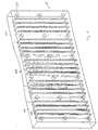
- FIG. 1 shows the back of a Kokillenbreitseite 100 a funnel mold.
- the size of the funnel opening 108 of the mold is preferably in a range between 5 and 30 mm.
- FIG. 1 it can be seen that groove-shaped cooling channels 110 have been milled into the casting plate in the form of cooling slots from the rear side R of the wide side of the casting 100.
- the cooling channels are tapered towards the upper edge 105 of the funnel mold, because there the thickness of the broad side of the mold is reduced.
- 100 holes 120 can be seen in Figure 1 on the back of the Kokillenbreitseite, which serve to receive fastening bolts for attachment of a channel box (not shown here) at the back of Kokillenbreitseite 100.
- the water tank is used to provide the cooling water for flowing through the cooling channels 110 in the Kokillenbreitseite 100th
- the cooling channels 110 are relatively narrow in the present invention compared to otherwise conventional cooling channels; their width is typically only between 5 and 15 mm. At the same time, for example, its depth is between 10 and 25 mm. Due to the aforementioned taper, that is, a change in the depth of the cooling slots over the length as well as the mold width and the flow rate of the cooling water and thus the removal of heat in individual heights and widths of Kokillenbreitseite would be different.
- the temperature profile of the Kokillenbreitseite on their back opposite working or Eing manseite and is also influenced by the wall thickness of the copper in front of the cooling channels 110 to the working side.
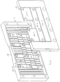
- Figures 2 - 5 show a first embodiment of the inventive design of a Kokillenbreitseite, in particular for recesses on the back and for associated filler.
- FIG. 2 shows, on the one hand, a rear side R of a mold broad side prepared according to the first exemplary embodiment with a plurality of corresponding recesses of different depths and, on the other hand, suitable filling pieces 140-1,... 5 for filling the recesses A1,..., A5.
- the recesses A1, ..., A5 according to the first embodiment can be seen that they are formed symmetrically to Kokillenmitte out, so that transversely to the longitudinal direction of the cooling channels 110, a symmetrical heat distribution can be realized.
- the example shown here has five recesses A1, ..., A5 of different depth, which are arranged immediately adjacent to each other.
- the five different recesses are on the one hand in the open rear side R of Kokillenbreitseite of Figure 2 can be seen; but they are also represented by the also shown in Figure 2 five different patches 140-1, ...- 5 according to the first embodiment for filling the corresponding recesses.
- the cooling channels in the region of the funnel opening 108 are tapered towards the upper edge 105 of the mold, as explained in FIG. 1, it is necessary for the realization of a substantially constant flow rate of cooling water through the cooling channels in this region that the recesses A1, .. .A5 in the upper region of Kokillenbreitseite 100, where the cooling channels 110 are not formed very deep, are formed less deep than in the lower part of the Kokillenbreitseite, where the cooling channels have a larger cross-section due to their greater depth.
- the difference between the depths of two adjacent recesses is for example between 0.5 and 4 mm, but preferably between 1 and 2 mm.
- the cross-section of the cooling channels 110 can then be integrally or stepwise over the entire height of the chill broadside 100 at least approximately.
- the filling pieces 140-1,..., -5 in the case of a plan view of the rear side R of the broadside of the mold 100 are substantially rectangular or U-shaped and each have one constant thickness corresponding to the depth of the recesses A1, ..., A5 to be covered by them.
- the holes 120 remain, as can be seen in Figure 2, in the preparation of the recesses and cooling channels on the back of Kokillenbreitseite 100 obtained by the environment of these holes 120 is excluded from the recess.
- the contact surfaces of all fastening webs are preferably in one plane and thus offer a good opportunity to fasten the mold plate on the water tank without mechanical stresses.
- the holes have on their inside a thread for fixing a fastening bolt, wherein the depth of the threaded hole can be up to 5 mm deeper than the depth of the adjacent cooling slots. In general, the depth of the cooling channels 110 in the region of the threads to equalize the temperature profile on the working side of Kokillenbreitseite 100 may be locally increased.
- the individual filling pieces 140-1,..., -5 shown in FIG. 2 can be connected together to form a one-piece overall filling piece.
- the individual patches or the Obstll choir can be constructed in one piece or in the form of a sandwich, that is layered.
- the filler pieces 140-1, ..., -5 are made of heat-conducting material in the form of a filler plate made of copper or a copper alloy.
- the filler can also be made of a non-magnetic material, preferably made of plastic.
- Figure 3 shows the known from Figure 2 Kokillenbreitseite 100 and the associated filling pieces 140-1, ..., -5 in the assembled state.
- the thicknesses of the filling pieces 140-1, ..., -5 are formed slightly smaller than the depths of the recesses which they are intended to cover, so that in the assembled state the mold plate rests only in the edge region and the fastening webs on the water tank.
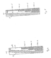
- FIG. 4 shows a first cross section along the section line IV-IV through the broad side of the mold according to FIG. 3. It can be seen that the cooling channel 110 was left in its original cross-section in the upper region of the broadside of the mold, ie in the region of the mold opening; There, the depth of the cooling channel 110 is not reduced by a filler. Furthermore, it can be seen that the profile of the depth of the cooling channel 110 in the Kokillenbreitseite 100 in the region of the intersecting recesses due to the there attached patches 140-2, ..., -4 is set stepwise locally. With the recesses and filling pieces and a different cross-section of the cooling channel 110 can be adjusted and the changed water passage velocity a correspondingly changed heat profile on the pouring A of the pouring plate 100. With appropriate design of the recess with an inclined surface and complementary shaped filling pieces is a continuous adjustment of the cooling channel cross section reachable.
- FIG. 5 shows a second cross section along the section line V-V through the assembled wide side of the chipboard 100 shown in FIG. 3.
- the statements made for FIG. 4 equally apply to FIG. 5, with the only difference that the cross section of the cooling channel 110 is also in the upper region of FIG Kokillenbreitseite 110 by a filler 140-5 and thus the flow rate of the cooling water was set there.
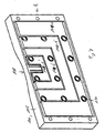
- FIGS 6 to 9 illustrate a second embodiment according to the invention, wherein the same technical features are designated by the same reference numerals.
- the second embodiment differs from the first embodiment in the form of the patches 140-1, 140-2, 140-3 according to the second embodiment, unlike the first embodiment not rectangular, but U-shaped. Due to their modified embodiment, these patches are denoted in the figures 6 to 9 each with an apostrophe in their reference numerals. Analogously, the recesses A1 ', A2' and A3 'provided for these filling pieces are now likewise U-shaped in the second exemplary embodiment.
- the fourth filling piece 140-4 was also already U-shaped in the first embodiment and thus remains unchanged in the second embodiment.
- FIG. 6 shows, analogously to FIG. 2, the rear side R of the mold broadside with the recesses A1 ', A2', A3 'and A4 formed according to the second embodiment of the invention and the associated filling pieces 141-1', 140-2 ', 140-3'. and 140-4 for filling the recesses.
- FIG. 7 shows the rear side R of the wide-side mold with inserted filling pieces according to the second exemplary embodiment.
Landscapes
- Engineering & Computer Science (AREA)
- Mechanical Engineering (AREA)
- Continuous Casting (AREA)
- Moulds For Moulding Plastics Or The Like (AREA)
- Molds, Cores, And Manufacturing Methods Thereof (AREA)
- Organic Low-Molecular-Weight Compounds And Preparation Thereof (AREA)
Abstract
Description
- Die Erfindung betrifft eine Kokillenbreitseite einer Trichterkokille zum Gießen von Metall, insbesondere von Stahl.
- Eine derartige Kokillenbreitseite ist zum Beispiel aus der deutschen Offenlegungsschrift
DE 198 29 606 A1 bekannt. Die dort offenbarte Breitseite der Kokille weist auf ihrer Wasserseite, nachfolgend Rückseite genannt, eine Mehrzahl von nutenförmigen Kühlkanälen auf, welche aufgrund der trichterförmigen Außenfläche bzw. Eingießseite der Gießplatte zu deren oberen Rand hin verjüngt sind. Neben den Kühlkanälen sind auf der Rückseite der Kokillenbreitseite Aussparungen vorhanden, die sich jeweils in Längsrichtung der Kühlkanäle über die gesamte Höhe der Breitseite erstrecken und jeweils einen Kühlkanal betreffen. Die Aussparungen sind mit geeignet dimensionierten Füllstücken verfüllt. Die Füllstücke ragen jeweils ein Stück weit in die Kühlkanäle hinein und dienen insofern zum Definieren der Größe des Querschnitts der Kühlkanäle in der Breitseite. Zur Befestigung sind die Füllstücke, in den Kühlkanälen zugeordneten, Hinterschneidungen eingeführt. Das Ausbilden der Hinterschneidungen und das Fertigen der Füllstücke mit einem zur Begrenzung des Querschnitts der Kühlkanäle geeigneten komplexen Profilquerschnitt ist konstruktiv recht aufwendig und deshalb teuer. - Der Erfindung liegt die Aufgabe zugrunde, eine bekannte Kokillenbreitseite für eine Trichterkokille mit mehreren Kühlkanälen im Hinblick auf die Einstellung einer im wesentlichen konstanten Durchflussgeschwindigkeit eines Kühlmediums durch den Kühlkanal konstruktiv zu vereinfachen.
- Diese Aufgabe wird durch den Gegenstand des Patentanspruchs 1 gelöst. Demnach ist die erfindungsgemäße Kokillenbreitseite dadurch gekennzeichnet, dass die Aussparung so ausgeformt ist, dass sie die Kühlkanäle quer zu der Längsrichtung durchkreuzt, dass sie in ihrer Ausdehnung in Längsrichtung der Kühlkanäle zumindest auf einen Teilabschnitt der Kühlkanäle beschränkt ist, und in dieser Längsrichtung einen rechteckförmigen und/oder keilförmigen Querschnitt aufweist, so dass die Tiefe der Kühlkanäle in der Kokillenbreitseite im Bereich der durchkreuzenden Aussparung entsprechend dem Querschnitt der Aussparung in Längsrichtung des Kühlkanals einstellbar ist und mit entsprechenden Füllstücken ausgefüllt ist.
- Die beanspruchte Ausformung der Aussparung quer zur Längsrichtung der Kühlkanäle ermöglicht vorteilhafterweise im Zusammenwirken mit einem die Aussparung ausfüllenden Füllstück eine einfache und preisgünstige Möglichkeit zur lokalen Einstellung der gewünschten Durchflussgeschwindigkeit eines Kühlmediums durch den Kühlkanal im Bereich der durchkreuzenden Aussparung. Weil die Aussparung den Kühlkanal durchkreuzt, kann das Füllstück einfach lang gestreckt ausgebildet sein, so dass es die Aussparung ausfüllt; insbesondere braucht es nicht in der Weise 3-dimensional verwinkelt ausgebildet zu sein, so dass es nicht nur in die Aussparung, sondern gleichzeitig auch ein stückweit in den Kühlkanal hinragt, wie dies in dem oben erwähnten Stand der Technik der Fall ist. Die Tiefe der Aussparung bzw. die Dicke des sie ausfüllenden Füllstückes definierten die Größe des in der Gießplatte verbleibenden Restquerschnitts des Kühlkanals bzw. das Ausmaß, inwieweit der Querschnitt des Kühlkanals im Bereich der durchkreuzenden Aussparung lokal verringert ist.
- Gemäß der Erfindung sind der Querschnitt der Aussparung in Längsrichtung der Kühlkanäle rechteckförmig und das zugehörige Füllstück quaderförmig ausgebildet; sowohl die Aussparung wie auch das Füllstück sind dann besonders einfach und preisgünstig herzustellen. Es ergibt sich dann eine lokale stufenförmige Verringerung des Querschnitts der Kühlkanäle im Trichterbereich, wodurch der gewünschte Strömungsquerschnitt eingestellt wird. Ist das Füllstück an der Anlagefläche zu den Kühlkanälen mit einer Schrägfläche ausgebildet und die Aussparung ebenfalls mit einer kompatiblen Schrägfläche ausgebildet, so lässt sich ein stufenloser Kühlkanalquerschnitt einstellen.
- Die Ausbildung der Aussparung und damit auch die Einstellung der Durchflussgeschwindigkeit des Kühlmediums symmetrisch zur Kokillenmitte hat den Vorteil, dass das gegossene Metall symmetrisch zur Kokillenmitte abgekühlt wird; auf diese Weise wird eine ungleiche Gussqualität über die Gießbreite des gegossenen Metalls verhindert.
- Wenn die ursprünglich in der Rückseite der Kokillenbreitseite vorgesehenen Kühlkanäle sich zum Beispiel aufgrund der trichterförmigen Ausbildung der Kokille zum oberen Rand der Kokille hin stark verjüngt, ist es vorteilhaft, die Einstellung der gewünschten Durchflussgeschwindigkeit des Kühlmediums nicht lediglich an einer Stelle, sondern gleichzeitig an mehreren Stellen entlang der Kühlkanäle vorzunehmen. Dies geschieht erfindungsgemäß durch mehrere Aussparungen, die auf der Rückseite der Kokillenplatte über deren Höhe verteilt angeordnet sind. Im Hinblick auf die Einstellung einer gewünschten Verteilung der Durchflussgeschwindigkeit des Kühlmediums entlang des Kühlkanals ist es vorteilhaft, wenn die einzelnen Aussparungen unterschiedliche Tiefen bzw. die entsprechenden Füllstücke entsprechende komplementäre Dicken aufweisen, in Anlehnung an den gewünschten Verlauf der Tiefe der Kühlkanäle in der Kokillenplatte.
- Die unmittelbar benachbarte Anordnung mehrerer Aussparungen führt zu einer Gesamtaussparung in der Rückseite der Kokillenbreitseite mit terrassenförmig ausgeformten Boden, wobei die Tiefe der einzelnen Stufen des terrassenförmigen Bodens mit zunehmender Entfernung vom oberen Rand der Kokille vorzugsweise zunimmt. Die Bildung der Gesamtaussparung zumindest im Trichterbereich hat den Vorteil, dass ein einziges Gesamtfüllstück vorbereitet werden kann zum Abdecken bzw. Verfüllen der Gesamtaussparung. Gegenüber einzelnen Füllstücken ist die Platzierung bzw. Anordnung des einen Gesamtfüllstücks auf der Rückseite der Kokillenbreitseite weniger zeitaufwendig.
- An der Rückseite der Kokillenbreitseite ist typischerweise ein Wasserkasten befestigt zum Bereitstellen von Kühlwasser für die Kühlkanäle. Zur Befestigung dieses Wasserkastens sieht die Erfindung vor, dass beim Ausformen der Kühlkanäle und der Aussparungen auf der Rückseite der Kokillenbreitseite Befestigungsstege stehen bleiben; diese sind dann einstückig mit der Kokillenbreitseite ausgebildet. Die Befestigungsstege weisen Gewinde auf.
- Das Füllstück kann über seine gesamte Dicke einstückig, mehrstückig, oder geschichtet auf gebaut sein. Es ist entweder aus wärmeleitendem Material, vorzugsweise aus Kupfer oder einer Kupferlegierung gefertigt oder alternativ kann es aus einem nicht magnetischem Material, vorzugsweise aus Kunststoff gefertigt sein.
- Weitere vorteilhafte Ausgestaltungen der erfindungsgemäßen Kokillenbreitseite sind Gegenstand der Unteransprüche.
- Der Erfindung sind insgesamt 7 Figuren beigefügt, wobei
- Figur 1
- die Rückseite einer Kokillenbreitseite mit darin ausgeformten, nutenförmigen Kühlkanälen;
- Figur 2
- die Rückseite der Kokillenbreitseite mit erfindungsgemäß ausgeformten Aussparungen und Füllstücke zum Auffüllen der Aussparungen;
- Figur 3
- die Rückseite der Kokillenbreitseite mit eingesetzten Füllstücken;
- Figur 4
- einen ersten Querschnitt durch die Kokillenbreitseite gemäß Figur 3; und entlang der Schnittlinie IV-IV;
- Figur 5
- einen zweiten Querschnitt durch die Kokillenbreitseite gemäß Figur 3 entlang der Schnittlinie V-V;
- Figur 6
- die Rückseite der Kokillenbreitseite mit gemäß einem zweiten Ausführungsbeispiel ausgeformten Aussparungen und Füllstücke zum Auffüllen dieser Aussparungen; und
- Figur 7
- die Rückseite der Kokillenbreitseite gemäß dem zweiten Ausführungsbeispiel mit eingesetzten Füllstücken
- Die Erfindung wird nachfolgend in Form von Ausführungsbeispielen unter Bezugnahme auf die genannten Figuren beschrieben.
- Figur 1 zeigt die Rückseite einer Kokillenbreitseite 100 einer Trichterkokille. Die Größe der Trichteröffnung 108 der Kokille liegt vorzugsweise in einem Bereich zwischen 5 und 30 mm. In Figur 1 ist zu erkennen, dass von der Rückseite R der Kokillenbreitseite 100 her nutenförmige Kühlkanäle 110 in Form von Kühlschlitzen in die Gießplatte hineingefräst wurden. Im Bereich der Trichteröffnung sind die Kühlkanäle zum oberen Rand 105 der Trichterkokille hin verjüngt, weil dort auch die Dicke der Kokillenbreitseite verringert ist. Weiterhin sind in Figur 1 auf der Rückseite der Kokillenbreitseite 100 Bohrungen 120 zu erkennen, welche zur Aufnahme von Befestigungsbolzen zur Befestigung eines Wasserkastens (hier nicht gezeigt) an der Rückseite der Kokillenbreitseite 100 dienen. Der Wasserkasten dient zum Bereitstellen des Kühlwassers zum Durchströmen der Kühlkanäle 110 in der Kokillenbreitseite 100.
- Die Kühlkanäle 110 sind bei der vorliegenden Erfindung im Vergleich zu ansonsten üblichen Kühlkanälen relativ schmal ausgebildet; ihre Breite liegt typischerweise lediglich zwischen 5 und 15 mm. Gleichzeitig liegt ihre Tiefe beispielsweise zwischen 10 und 25 mm. Aufgrund der erwähnten Verjüngung, das heißt einer Veränderung der Tiefe der Kühlschlitze über deren Länge als auch über die Kokillenbreite wäre auch die Durchflussgeschwindigkeit des Kühlwassers und damit der Abtransport von Wärme in einzelnen Höhen und Breiten der Kokillenbreitseite unterschiedlich. Das Temperaturprofil der Kokillenbreitseite an deren der Rückseite gegenüberliegenden Arbeits- bzw. Eingießseite und wird weiterhin auch durch die Wandstärke des Kupfers vor den Kühlkanälen 110 zur Arbeitsseite hin beeinflusst.
- Um dieses Temperaturprofil auf der Arbeitsseite in gewünschter Weise einzustellen bzw. beeinflussen zu können wird erfindungsgemäß vorgeschlagen, auf der Rückseite R der Kokillenbreitseite an geeigneten Positionen Aussparungen A1, ..., 5 vorzunehmen, die die Kühlkanäle quer zu dessen Längsrichtung durchkreuzen. Während des Betriebs der Kokille und der Kokillenbreitseite 100 sind die Aussparungen dann zumindest teilweise mit den entsprechend dem von der Aussparung aufgespannten Volumen dimensionierten Füllstücken 140-1, ...-5 verfüllt, wodurch die Tiefe der von der Aussparung durchkreuzten Kühlkanäle im Bereich dieser verfüllten Aussparung lokal stufenförmig eingestellt wird.
- Die Figuren 2 - 5 zeigen ein erstes Ausführungsbeispiel für die erfindungsgemäße Ausgestaltung einer Kokillenbreitseite, insbesondere für Aussparungen auf deren Rückseite und für zugehörige Füllstücke.
- Figur 2 zeigt zum einen eine gemäß dem ersten Ausführungsbeispiel ausgearbeitete Rückseite R einer Kokillenbreitseite mit mehreren entsprechenden Aussparungen unterschiedlicher Tiefe und zum anderen geeignete Füllstücke 140-1, ...-5 zum Auffüllen der Aussparungen A1, ..., A5.
- Bei den Aussparungen A1, ..., A5 gemäß dem ersten Ausführungsbeispiel ist zu erkennen, dass sie symmetrisch zur Kokillenmitte hin ausgebildet sind, so dass quer zur Längsrichtung der Kühlkanäle 110 eine symmetrische Wärmeverteilung realisiert werden kann. Insgesamt weist das hier gezeigte Beispiel fünf Aussparungen A1, ..., A5 unterschiedlicher Tiefe auf, die unmittelbar benachbart zueinander angeordnet sind. Die fünf verschiednen Aussparungen sind zum einen in der geöffneten Rückseite R der Kokillenbreitseite der Figur 2 zu erkennen; sie sind aber auch durch die ebenfalls in Figur 2 gezeigten fünf verschiedenen Füllstücke 140-1, ...-5 gemäß dem ersten Ausführungsbeispiel zum Auffüllen der entsprechenden Aussparungen repräsentiert.
- Weil die Kühlkanäle im Bereich der Trichteröffnung 108 zum oberen Rand 105 der Kokille hin verjüngt sind, wie in Figur 1 erläutert, ist es zur Realisierung einer im Wesentlichen konstanten Durchflussgeschwindigkeit von Kühlwasser durch die Kühlkanäle in diesem Bereich erforderlich, dass die Aussparungen A1, ...A5 im oberen Bereich der Kokillenbreitseite 100, wo die Kühlkanäle 110 nicht sehr tief ausgebildet sind, weniger tief ausgebildet sind als im unteren Bereich der Kokillenbreitseite, wo die Kühlkanäle aufgrund ihrer größeren Tiefe einen größeren Querschnitt aufweisen. Es ergibt sich dann die in Figur 2 erkennbare terrassenförmige Ausbildung der Rückseite der Kokillenbreitseite; dabei beträgt die Differenz zwischen den Tiefen zweier benachbarter Aussparungen beispielsweise zwischen 0,5 und 4 mm vorzugsweise jedoch zwischen 1 und 2 mm. Durch Auffüllen der Aussparungen A1, ..., A5 mit den ebenfalls in Figur 2 gezeigten entsprechend dicken Füllstücken 140-1, ..., -5 lässt sich dann der Querschnitt der Kühlkanäle 110 integrativ bzw. stufenweise über die gesamte Höhe der Kokillenbreitseite 100 zumindest näherungsweise einstellen. Wie in Figur 2 zu erkennen ist, sind die Füllstücke 140-1, ..., -5 bei Draufsicht auf die Rückseite R der Kokillenbreitseite 100 im Wesentlichen rechteckig oder u-förmig ausgebildet und haben jeweils eine konstante Dicke, entsprechend der Tiefe der von ihnen abzudeckenden Aussparungen A1, ..., A5.
- Die Bohrungen 120 bleiben, wie in Figur 2 zu erkennen ist, bei der Ausarbeitung der Aussparungen und Kühlkanäle auf der Rückseite der Kokillenbreitseite 100 erhalten, indem die Umgebung dieser Bohrungen 120 von der Aussparung ausgenommen wird. Somit bleiben auf der Rückseite R der Kokillenbreitseite Befestigungsstege 130 mit Anlageflächen 132 und mit Bohrungen 120 stehen. Die Anlageflächen aller Befestigungsstege liegen vorzugsweise in einer Ebene und bieten so eine gute Möglichkeit, die Kokillenplatte auf dem Wasserkasten ohne mechanische Spannungen zu befestigen. Die Bohrungen weisen auf ihrer Innenseite ein Gewinde auf zur Befestigung eines Befestigungsbolzens, wobei die Tiefe der Gewindebohrung um bis zu 5 mm tiefer liegen kann als die Tiefe der benachbarten Kühlschlitze. Allgemein kann die Tiefe der Kühlkanäle 110 im Bereich der Gewinde zur Vergleichmäßigung des Temperaturprofils auf der Arbeitsseite der Kokillenbreitseite 100 örtlich vergrößert sein.
- Die in Figur 2 gezeigten einzelnen Füllstücke 140-1, ..., -5 können zu einem einteiligen Gesamtfüllstück miteinander verbunden sein. Die einzelnen Füllstücke oder das Gesamtfüllstück können einteilig oder in Form eines Sandwichs, das heißt geschichtet aufgebaut sein. Vorzugsweise sind die Füllstücke 140-1, ..., -5 aus wärmeleitendem Material in Form eines Füllbleches aus Kupfer oder einer Kupferlegierung gefertigt. Alternativ können die Füllstücke auch aus einem nicht magnetischen Material, vorzugsweise aus Kunststoff gefertigt sein.
- Figur 3 zeigt die aus Figur 2 bekannte Kokillenbreitseite 100 und die zugehörigen Füllstücke 140-1, ..., -5 in zusammengebautem Zustand. Vorzugsweise sind die Dicken der Füllstücke 140-1, ..., -5 etwas geringer als die Tiefen der Aussparungen ausgebildet, welche sie abdecken sollen, so dass in zusammengebautem Zustand die Kokillenplatte nur im Randbereich und den Befestigungsstegen auf dem Wasserkasten anliegt.
- Figur 4 zeigt einen ersten Querschnitt entlang der Schnittlinie IV - IV durch die Kokillenbreitseite gemäß Figur 3. Es ist zu erkennen, dass im oberen Bereich der Kokillenbreitseite, das heißt im Bereich der Kokillenöffnung, der Kühlkanal 110 in seinem ursprünglichen Querschnitt belassen wurde; dort ist die Tiefe des Kühlkanals 110 nicht durch ein Füllstück verringert. Weiterhin ist zu erkennen, dass der Verlauf der Tiefe des Kühlkanals 110 in der Kokillenbreitseite 100 im Bereich der durchkreuzenden Aussparungen aufgrund der dort angebrachten Füllstücke 140-2, ..., -4 stufenförmig lokal eingestellt ist. Mit den Aussparungen und Füllstücken kann auch ein unterschiedlicher Querschnitt des Kühlkanals 110 eingestellt werden und durch die veränderte Wasserdurchtrittsgeschwindigkeit ein entsprechend verändertes Wärmeprofil auf der Eingießseite A der Gießplatte 100. Bei entsprechender Ausbildung der Aussparung mit einer Schrägfläche und komplementär ausgebildeten Füllstücken ist eine stufenlose Einstellung des Kühlkanalquerschnitts erreichbar.
- Figur 5 zeigt einen zweiten Querschnitt entlang der Schnittlinie V - V durch die in Figur 3 gezeigte zusammengebaute Kokillenbreitseite 100. Die für Figur 4 gemachten Aussagen gelten für Figur 5 gleichermaßen, mit dem einzigen Unterschied, dass der Querschnitt des Kühlkanals 110 auch im oberen Bereich der Kokillenbreitseite 110 durch ein Füllstück 140-5 und damit die Durchflussgeschwindigkeit des Kühlwassers dort eingestellt wurde.
- Die Figuren 6 bis 9 stellen ein zweites Ausführungsbeispiel gemäß der Erfindung dar, wobei gleiche technische Merkmale mit gleichen Bezugzeichen bezeichnet sind. Das zweite Ausführungsbeispiel unterscheidet sich von dem ersten Ausführungsbeispiel in der Form der Füllstücke 140-1, 140-2, 140-3 die gemäß dem zweiten Ausführungsbeispiel im Unterschied zu dem ersten Ausführungsbeispiel nicht rechteckig, sondern U-förmig ausgebildet sind. Aufgrund ihrer veränderten Ausführungsform sind diese Füllstücke in den Figuren 6 bis 9 jeweils mit einem Hochkomma in ihren Bezugzeichen bezeichnet. Analog sind die für diese Füllstücke vorgesehenen Aussparungen A1', A2' und A3' in dem zweiten Ausführungsbeispiel nunmehr ebenfalls U-förmig ausgebildet. Das vierte Füllstück 140-4 war auch bereits in dem ersten Ausführungsbeispiel U-förmig ausgebildet und bleibt insofern bei dem zweiten Ausführungsbeispiel unverändert.
- Figur 6 zeigt analog zu Figur 2 die Rückseite R der Kokillenbreitseite mit den gemäß dem zweiten Ausführungsbeispiel der Erfindung ausgeformten Aussparungen A1', A2', A3' und A4 sowie die zugehörigen Füllstücke 141-1', 140-2', 140-3' und 140-4 zum Auffüllen der Aussparungen.
- Figur 7 zeigt die Rückseite R der Breitseitenkokille mit eingesetzten Füllstücken gemäß dem zweiten Ausführungsbeispiel.
Claims (17)
- Kokillenbreitseite (100) einer Trichterkokille zum Gießen von Metall, insbesondere Stahl, mit:nutenförmigen Kühlkanälen (110) in der Rückseite (R) der Kokillenplatte (100); mindestens einer Aussparung (A1, ..., A5) in der Rückseite; undmindestens einem Füllstück (140-1, ..., 140-5) zum zumindest teilweisen Verschließen der Aussparung;dadurch gekennzeichnet,dass die Aussparung (A1, ..., A5) so ausgeformt ist, dasssie die Kühlkanäle (110) quer zu deren Längsrichtung durchkreuzt; und dass sie in ihrer Ausdehnung in Längsrichtung des Kühlkanals zumindest auf einen Teilabschnitt des Kühlkanals beschränkt ist und in dieser Längsrichtung einen rechteckförmigen und/oder keilförmigen Querschnitt aufweist, so dass die Tiefe des Kühlkanals (110) in der Kokillenbreitseite (100) im Bereich der durchkreuzenden Aussparungen stufenförmig und/oder linear einstellbar ist und mit entsprechenden Füllstücken (140-1, ..., 140-5) ausgeführt ist.
- Kokillenbreitseite (100) nach Anspruch 1,
dadurch gekennzeichnet,
dass die Trichteröffnung zwischen 5 und 30 mm beträgt. - Kokillenbreitseite (100) nach Anspruch 1 oder 2
dadurch gekennzeichnet, dass die Aussparung (A2, ..., A4) symmetrisch zur Kokillenmitte ausgebildet ist. - Kokillenbreitseite (100) nach einem der vorangegangenen Ansprüche,
dadurch gekennzeichnet,
dass die Aussparung (A1, ..., A5) und das zugehörige Füllstück bei Draufsicht auf die Rückseite (R) der Kokillenbreitseite (100) rechteckig oder vorzugsweise U-förmig ausgebildet sind. - Kokillenbreitseite (100) nach einem der vorangegangenen Ansprüche,
dadurch gekennzeichnet,
dass in der Rückseite der Kokillenbreitseite (100) über die Höhe der Kokillenbreitseite verteilt mehrere Aussparungen (A1, ..., A5) mit jeweils unterschiedlicher Tiefe ausgebildet sind, wobei die Tiefen der einzelnen Aussparungen mit zunehmender Entfernung von dem oberen Rand (105) und von der Kokillenmitte der Kokille zunehmen. - Kokillenbreitseite (100) nach Anspruch 5,
dadurch gekennzeichnet,
dass der Unterschied in der Tiefe zwischen zwei benachbarten Aussparungen (A1, A2) zwischen 0,5 und 4 mm, vorzugsweise zwischen 1 und 2 mm beträgt. - Kokillenbreitseite (100) nach Anspruch 5 oder 6,
dadurch gekennzeichnet,
dass die mehreren Aussparungen (A1, ..., A5) unmittelbar benachbart angeordnet sind und eine Gesamtaussparung in der Rückseite der Gießplatte mit terrassenförmig ausgeformtern Boden bilden. - Kokillenbreitseite (100) nach einem der vorangegangenen Ansprüche,
gekennzeichnet durch
mindestens einen auf der Rückseite (R) der Kokillenbreitseite (100) vorzugsweise einstückig mit dieser ausgebildeten Befestigungssteg (130) zum Befestigen der Kokillenbreitseite (100) mit ihrer Rückseite an einem Wasserkasten zum Bereitstellen von Kühlwasser für den Kühlkanal (110), wobei der Befestigungssteg (130) beim Ausbilden des nutenförmigen Kühlkanals und der Aussparung in der Rückseite der Kokillenbreitseite (100) stehen geblieben ist. - Kokillenbreitseite (100) nach Anspruch 8,
dadurch gekennzeichnet,
dass der Befestigungssteg eine Bohrung (120) und ein Gewinde aufweist. - Kokillenbreitseite (100) nach einem der vorangegangenen Ansprüche,
dadurch gekennzeichnet, dass das Füllstück (140-1, ..., -5) in seinen äußeren Abmessungen und in seiner Dicke zumindest näherungsweise komplementär zu der Aussparung (A1, ..., A5) ausgebildet ist, so dass es das durch die Aussparung aufgespannte Volumen ausfüllt. - Kokillenbreitseite (100) nach einem der vorangegangenen Ansprüche,
dadurch gekennzeichnet,
dass das Füllstück (140-1, ..., -5) einstückig, mehrstückig oder geschichtet aufgebaut ist. - Kokillenbreitseite (100) nach einem der vorangegangenen Ansprüche,
dadurch gekennzeichnet,
dass die Füllstücke (140-1, ..., -5) zum Abdecken mehrer Aussparungen (A1, ..., A5) zu einem Gesamtfüllstück miteinander verbunden sind, welches die Rückseite der Kokillenbreitseite (100) in vorzugsweise vollflächig planarer Ausbildung repräsentiert. - Kokillenbreitseite (100) nach einem der vorangegangenen Ansprüche,
dadurch gekennzeichnet,
dass das Füllstück (140-1, .., -5) als Füllblech aus einem wärmeleitendem Material, vorzugsweise aus Kupfer oder einer Kupferlegierung gebildet ist. - Kokillenbreitseite (100) nach einem der Ansprüche 1 bis 13,
dadurch gekennzeichnet,
dass das Füllstück (140-1, ..., -5) aus nicht magnetischem Material, vorzugsweise aus Kunststoff gefertigt ist. - Kokillenbreitseite (100) nach einem der Ansprüche 1 bis 14,
dadurch gekennzeichnet,
dass die Aussparungen (A1 ... A5) zu mindestens teilweise U-förmig ausgebildet sind. - Kokillenbreitseite (100) nach einem Ansprüche 1 bis 15,
dadurch gekennzeichnet,
dass die Geometrie der einzelnen Kühlkanäle (110) und damit der Wassergeschwindigkeit zur Einstellung eines gewünschten Temperaturprofils der Arbeitsseite der Kokillenplatte unterschiedlich ausgeführt ist. - Kokillenbreitseite nach einem der Ansprüche 1 bis 16,
dadurch gekennzeichnet,
dass die einzelnen Füllstücke (140-1, ..., -5) z.B. durch Weichlöten oder Kleben verbunden sind.
Applications Claiming Priority (1)
| Application Number | Priority Date | Filing Date | Title |
|---|---|---|---|
| DE102005040634A DE102005040634A1 (de) | 2005-08-27 | 2005-08-27 | Kokillenbreitseite einer Trichterkokille |
Publications (3)
| Publication Number | Publication Date |
|---|---|
| EP1757385A2 true EP1757385A2 (de) | 2007-02-28 |
| EP1757385A3 EP1757385A3 (de) | 2008-12-10 |
| EP1757385B1 EP1757385B1 (de) | 2010-03-24 |
Family
ID=37491967
Family Applications (1)
| Application Number | Title | Priority Date | Filing Date |
|---|---|---|---|
| EP06016823A Not-in-force EP1757385B1 (de) | 2005-08-27 | 2006-08-11 | Kokillenbreitseite einer Trichterkokille |
Country Status (4)
| Country | Link |
|---|---|
| US (1) | US7798202B2 (de) |
| EP (1) | EP1757385B1 (de) |
| AT (1) | ATE461768T1 (de) |
| DE (2) | DE102005040634A1 (de) |
Cited By (4)
| Publication number | Priority date | Publication date | Assignee | Title |
|---|---|---|---|---|
| WO2008049398A1 (de) * | 2006-10-26 | 2008-05-02 | Sms Demag Ag | Stranggiesskokille |
| DE102008032672A1 (de) | 2008-07-10 | 2010-01-14 | Sms Siemag Aktiengesellschaft | Stranggießkokille |
| WO2010015399A1 (de) * | 2008-08-06 | 2010-02-11 | Sms Siemag Ag | Stranggiesskokille für flüssiges metall, insbesondere für flüssigen stahl |
| DE102018123948B3 (de) | 2018-09-27 | 2019-09-12 | Kme Germany Gmbh & Co. Kg | Kokillenplatte |
Families Citing this family (2)
| Publication number | Priority date | Publication date | Assignee | Title |
|---|---|---|---|---|
| DE102005041296A1 (de) * | 2005-08-31 | 2007-04-05 | Trw Automotive Gmbh | Gassackmodul |
| DE102009060240A1 (de) * | 2009-12-23 | 2011-06-30 | SMS Siemag AG, 40237 | Platte mit Kühlkanälen |
Citations (4)
| Publication number | Priority date | Publication date | Assignee | Title |
|---|---|---|---|---|
| DE19826522A1 (de) * | 1998-06-15 | 1999-12-16 | Schloemann Siemag Ag | Kokillenwand einer Stranggießkokille |
| DE19829606A1 (de) * | 1998-07-02 | 2000-01-05 | Schloemann Siemag Ag | Breitseite einer Brammenkokille |
| EP0987073A1 (de) * | 1998-09-17 | 2000-03-22 | Sms Schloemann-Siemag Aktiengesellschaft | Kokillenwand einer Stranggiesskokille |
| DE19903929A1 (de) * | 1999-02-01 | 2000-08-03 | Sms Demag Ag | Kokillenplatte einer Kokille mit trichterförmigem Eingießbereich zum Stranggießen von Metall |
Family Cites Families (3)
| Publication number | Priority date | Publication date | Assignee | Title |
|---|---|---|---|---|
| US3595302A (en) * | 1967-05-11 | 1971-07-27 | Schloemann Ag | Cooling structure for continuous-casting mold |
| JPS5731449A (en) * | 1980-07-31 | 1982-02-19 | Kouka Kuroomu Kogyo Kk | Mold for continuous casting of steel |
| DE10056910A1 (de) * | 2000-11-16 | 2002-05-29 | Sms Demag Ag | Knüppel- und Blockkokille mit partiell geregelter Wärmeabfuhr über Kokillenumfang und Kokillenhöhe |
-
2005
- 2005-08-27 DE DE102005040634A patent/DE102005040634A1/de not_active Withdrawn
-
2006
- 2006-08-11 AT AT06016823T patent/ATE461768T1/de active
- 2006-08-11 EP EP06016823A patent/EP1757385B1/de not_active Not-in-force
- 2006-08-11 DE DE502006006494T patent/DE502006006494D1/de active Active
- 2006-08-30 US US11/512,723 patent/US7798202B2/en not_active Expired - Fee Related
Patent Citations (4)
| Publication number | Priority date | Publication date | Assignee | Title |
|---|---|---|---|---|
| DE19826522A1 (de) * | 1998-06-15 | 1999-12-16 | Schloemann Siemag Ag | Kokillenwand einer Stranggießkokille |
| DE19829606A1 (de) * | 1998-07-02 | 2000-01-05 | Schloemann Siemag Ag | Breitseite einer Brammenkokille |
| EP0987073A1 (de) * | 1998-09-17 | 2000-03-22 | Sms Schloemann-Siemag Aktiengesellschaft | Kokillenwand einer Stranggiesskokille |
| DE19903929A1 (de) * | 1999-02-01 | 2000-08-03 | Sms Demag Ag | Kokillenplatte einer Kokille mit trichterförmigem Eingießbereich zum Stranggießen von Metall |
Cited By (9)
| Publication number | Priority date | Publication date | Assignee | Title |
|---|---|---|---|---|
| WO2008049398A1 (de) * | 2006-10-26 | 2008-05-02 | Sms Demag Ag | Stranggiesskokille |
| US8240357B2 (en) | 2006-10-26 | 2012-08-14 | Sms Siemag Ag | Extrusion die |
| DE102008032672A1 (de) | 2008-07-10 | 2010-01-14 | Sms Siemag Aktiengesellschaft | Stranggießkokille |
| WO2010003695A1 (de) | 2008-07-10 | 2010-01-14 | Sms Siemag Ag | Stranggiesskokille |
| WO2010015399A1 (de) * | 2008-08-06 | 2010-02-11 | Sms Siemag Ag | Stranggiesskokille für flüssiges metall, insbesondere für flüssigen stahl |
| CN102112255B (zh) * | 2008-08-06 | 2014-05-07 | Sms西马格股份公司 | 用于液态金属、特别用于液态钢的连续铸造金属铸型 |
| DE102018123948B3 (de) | 2018-09-27 | 2019-09-12 | Kme Germany Gmbh & Co. Kg | Kokillenplatte |
| WO2020064045A1 (de) | 2018-09-27 | 2020-04-02 | Kme Germany Gmbh & Co. Kg | Kokillenplatte |
| US11135645B2 (en) | 2018-09-27 | 2021-10-05 | Kme Special Products Gmbh & Co. Kg | Mold plate |
Also Published As
| Publication number | Publication date |
|---|---|
| DE102005040634A1 (de) | 2007-03-01 |
| US7798202B2 (en) | 2010-09-21 |
| EP1757385A3 (de) | 2008-12-10 |
| ATE461768T1 (de) | 2010-04-15 |
| DE502006006494D1 (de) | 2010-05-06 |
| US20080073483A1 (en) | 2008-03-27 |
| EP1757385B1 (de) | 2010-03-24 |
Similar Documents
| Publication | Publication Date | Title |
|---|---|---|
| EP2061078B1 (de) | Kühlkörper | |
| EP0441929B1 (de) | Vorrichtung zum extrudieren von kunststoff-mehrschichtfolien oder -platten | |
| EP1757385B1 (de) | Kokillenbreitseite einer Trichterkokille | |
| WO2000036154A1 (de) | Kühlplatte für einen ofen zur eisen- oder stahlerzeugung | |
| DE3727179C2 (de) | Verfahren zur Herstellung eines Schlingenbildnermoduls | |
| EP0143289A1 (de) | Herzstück für Weichen oder Kreuzungen und Verfahren zur Herstellung eines solchen Herzstückes | |
| EP3491186B1 (de) | Strömungsmodul und verfahren zur herstellung eines strömungsmoduls für einen stoffauflauf einer papiermaschine | |
| EP1770193B1 (de) | Wirkmaschinen-Barre und Verfahren zum Herstellen einer Wirkmaschinen-Barre | |
| EP1317978A1 (de) | Kokillenrohr zum Stranggiessen von Metallen | |
| EP0800907B1 (de) | Nadelverschlussdüse mit Spritzgiessform und Verschlussnadel | |
| DE69907562T2 (de) | Gießrohr zum Einführen von Flüssigmetall in eine Stranggußform für Metalle | |
| EP0123914B1 (de) | Gestanztes Strickwerkzeug für Strick- oder Wirkmaschinen | |
| EP1506826B1 (de) | Stranggiesskokille | |
| EP2083957B1 (de) | Stranggiesskokille | |
| EP0968779B1 (de) | Breitseite einer Brammenkokille | |
| DE19854932C2 (de) | Vakuum-Außenkalibrierung | |
| DE8913293U1 (de) | Gestanztes Strickwerkzeug für Textilmaschinen | |
| EP3461570A1 (de) | Stranggiesskokille | |
| DE3314417A1 (de) | Schluessel fuer zylinderschloesser | |
| EP1019208A1 (de) | Kokillenrohr für eine stranggiesskokille zum stranggiessen von stählen, insbesondere peritektischen stählen | |
| AT401487B (de) | Stranggiesskokille zum kontinuierlichen giessen von metall | |
| DE3604963A1 (de) | Einsatz zum unterteilen einer giessform | |
| DE19801728C1 (de) | Stranggießkokille | |
| AT401027B (de) | Stranggussmaschine zum kontinuierlichen horizontalen stranggiessen von metallen | |
| DE2114505A1 (de) | Kokille fur den Anbau an einen Warmhalteofen bzw an ein Metallaufnah megerat |
Legal Events
| Date | Code | Title | Description |
|---|---|---|---|
| PUAI | Public reference made under article 153(3) epc to a published international application that has entered the european phase |
Free format text: ORIGINAL CODE: 0009012 |
|
| 17P | Request for examination filed |
Effective date: 20060816 |
|
| AK | Designated contracting states |
Kind code of ref document: A2 Designated state(s): AT BE BG CH CY CZ DE DK EE ES FI FR GB GR HU IE IS IT LI LT LU LV MC NL PL PT RO SE SI SK TR |
|
| AX | Request for extension of the european patent |
Extension state: AL BA HR MK YU |
|
| PUAL | Search report despatched |
Free format text: ORIGINAL CODE: 0009013 |
|
| AK | Designated contracting states |
Kind code of ref document: A3 Designated state(s): AT BE BG CH CY CZ DE DK EE ES FI FR GB GR HU IE IS IT LI LT LU LV MC NL PL PT RO SE SI SK TR |
|
| AX | Request for extension of the european patent |
Extension state: AL BA HR MK RS |
|
| RAP1 | Party data changed (applicant data changed or rights of an application transferred) |
Owner name: SMS SIEMAG AG |
|
| AKX | Designation fees paid |
Designated state(s): AT BE BG CH CY CZ DE DK EE ES FI FR GB GR HU IE IS IT LI LT LU LV MC NL PL PT RO SE SI SK TR |
|
| GRAP | Despatch of communication of intention to grant a patent |
Free format text: ORIGINAL CODE: EPIDOSNIGR1 |
|
| GRAS | Grant fee paid |
Free format text: ORIGINAL CODE: EPIDOSNIGR3 |
|
| GRAA | (expected) grant |
Free format text: ORIGINAL CODE: 0009210 |
|
| AK | Designated contracting states |
Kind code of ref document: B1 Designated state(s): AT BE BG CH CY CZ DE DK EE ES FI FR GB GR HU IE IS IT LI LT LU LV MC NL PL PT RO SE SI SK TR |
|
| REG | Reference to a national code |
Ref country code: GB Ref legal event code: FG4D Free format text: NOT ENGLISH |
|
| REG | Reference to a national code |
Ref country code: CH Ref legal event code: EP |
|
| REG | Reference to a national code |
Ref country code: IE Ref legal event code: FG4D |
|
| REF | Corresponds to: |
Ref document number: 502006006494 Country of ref document: DE Date of ref document: 20100506 Kind code of ref document: P |
|
| REG | Reference to a national code |
Ref country code: NL Ref legal event code: VDEP Effective date: 20100324 |
|
| PG25 | Lapsed in a contracting state [announced via postgrant information from national office to epo] |
Ref country code: LT Free format text: LAPSE BECAUSE OF FAILURE TO SUBMIT A TRANSLATION OF THE DESCRIPTION OR TO PAY THE FEE WITHIN THE PRESCRIBED TIME-LIMIT Effective date: 20100324 |
|
| LTIE | Lt: invalidation of european patent or patent extension |
Effective date: 20100324 |
|
| PG25 | Lapsed in a contracting state [announced via postgrant information from national office to epo] |
Ref country code: LV Free format text: LAPSE BECAUSE OF FAILURE TO SUBMIT A TRANSLATION OF THE DESCRIPTION OR TO PAY THE FEE WITHIN THE PRESCRIBED TIME-LIMIT Effective date: 20100324 Ref country code: FI Free format text: LAPSE BECAUSE OF FAILURE TO SUBMIT A TRANSLATION OF THE DESCRIPTION OR TO PAY THE FEE WITHIN THE PRESCRIBED TIME-LIMIT Effective date: 20100324 Ref country code: PL Free format text: LAPSE BECAUSE OF FAILURE TO SUBMIT A TRANSLATION OF THE DESCRIPTION OR TO PAY THE FEE WITHIN THE PRESCRIBED TIME-LIMIT Effective date: 20100324 Ref country code: SI Free format text: LAPSE BECAUSE OF FAILURE TO SUBMIT A TRANSLATION OF THE DESCRIPTION OR TO PAY THE FEE WITHIN THE PRESCRIBED TIME-LIMIT Effective date: 20100324 |
|
| REG | Reference to a national code |
Ref country code: IE Ref legal event code: FD4D |
|
| PG25 | Lapsed in a contracting state [announced via postgrant information from national office to epo] |
Ref country code: RO Free format text: LAPSE BECAUSE OF FAILURE TO SUBMIT A TRANSLATION OF THE DESCRIPTION OR TO PAY THE FEE WITHIN THE PRESCRIBED TIME-LIMIT Effective date: 20100324 Ref country code: NL Free format text: LAPSE BECAUSE OF FAILURE TO SUBMIT A TRANSLATION OF THE DESCRIPTION OR TO PAY THE FEE WITHIN THE PRESCRIBED TIME-LIMIT Effective date: 20100324 Ref country code: GR Free format text: LAPSE BECAUSE OF FAILURE TO SUBMIT A TRANSLATION OF THE DESCRIPTION OR TO PAY THE FEE WITHIN THE PRESCRIBED TIME-LIMIT Effective date: 20100625 Ref country code: ES Free format text: LAPSE BECAUSE OF FAILURE TO SUBMIT A TRANSLATION OF THE DESCRIPTION OR TO PAY THE FEE WITHIN THE PRESCRIBED TIME-LIMIT Effective date: 20100705 Ref country code: EE Free format text: LAPSE BECAUSE OF FAILURE TO SUBMIT A TRANSLATION OF THE DESCRIPTION OR TO PAY THE FEE WITHIN THE PRESCRIBED TIME-LIMIT Effective date: 20100324 Ref country code: SE Free format text: LAPSE BECAUSE OF FAILURE TO SUBMIT A TRANSLATION OF THE DESCRIPTION OR TO PAY THE FEE WITHIN THE PRESCRIBED TIME-LIMIT Effective date: 20100324 |
|
| PG25 | Lapsed in a contracting state [announced via postgrant information from national office to epo] |
Ref country code: IS Free format text: LAPSE BECAUSE OF FAILURE TO SUBMIT A TRANSLATION OF THE DESCRIPTION OR TO PAY THE FEE WITHIN THE PRESCRIBED TIME-LIMIT Effective date: 20100724 Ref country code: SK Free format text: LAPSE BECAUSE OF FAILURE TO SUBMIT A TRANSLATION OF THE DESCRIPTION OR TO PAY THE FEE WITHIN THE PRESCRIBED TIME-LIMIT Effective date: 20100324 Ref country code: BG Free format text: LAPSE BECAUSE OF FAILURE TO SUBMIT A TRANSLATION OF THE DESCRIPTION OR TO PAY THE FEE WITHIN THE PRESCRIBED TIME-LIMIT Effective date: 20100624 Ref country code: CZ Free format text: LAPSE BECAUSE OF FAILURE TO SUBMIT A TRANSLATION OF THE DESCRIPTION OR TO PAY THE FEE WITHIN THE PRESCRIBED TIME-LIMIT Effective date: 20100324 |
|
| PLBE | No opposition filed within time limit |
Free format text: ORIGINAL CODE: 0009261 |
|
| STAA | Information on the status of an ep patent application or granted ep patent |
Free format text: STATUS: NO OPPOSITION FILED WITHIN TIME LIMIT |
|
| PG25 | Lapsed in a contracting state [announced via postgrant information from national office to epo] |
Ref country code: DK Free format text: LAPSE BECAUSE OF FAILURE TO SUBMIT A TRANSLATION OF THE DESCRIPTION OR TO PAY THE FEE WITHIN THE PRESCRIBED TIME-LIMIT Effective date: 20100324 Ref country code: PT Free format text: LAPSE BECAUSE OF FAILURE TO SUBMIT A TRANSLATION OF THE DESCRIPTION OR TO PAY THE FEE WITHIN THE PRESCRIBED TIME-LIMIT Effective date: 20100726 Ref country code: IE Free format text: LAPSE BECAUSE OF FAILURE TO SUBMIT A TRANSLATION OF THE DESCRIPTION OR TO PAY THE FEE WITHIN THE PRESCRIBED TIME-LIMIT Effective date: 20100324 |
|
| BERE | Be: lapsed |
Owner name: SMS SIEMAG AG Effective date: 20100831 |
|
| 26N | No opposition filed |
Effective date: 20101228 |
|
| PG25 | Lapsed in a contracting state [announced via postgrant information from national office to epo] |
Ref country code: MC Free format text: LAPSE BECAUSE OF NON-PAYMENT OF DUE FEES Effective date: 20100831 |
|
| REG | Reference to a national code |
Ref country code: CH Ref legal event code: PL |
|
| PG25 | Lapsed in a contracting state [announced via postgrant information from national office to epo] |
Ref country code: LI Free format text: LAPSE BECAUSE OF NON-PAYMENT OF DUE FEES Effective date: 20100831 Ref country code: CH Free format text: LAPSE BECAUSE OF NON-PAYMENT OF DUE FEES Effective date: 20100831 |
|
| REG | Reference to a national code |
Ref country code: FR Ref legal event code: ST Effective date: 20110502 |
|
| PG25 | Lapsed in a contracting state [announced via postgrant information from national office to epo] |
Ref country code: BE Free format text: LAPSE BECAUSE OF NON-PAYMENT OF DUE FEES Effective date: 20100831 Ref country code: FR Free format text: LAPSE BECAUSE OF NON-PAYMENT OF DUE FEES Effective date: 20100831 |
|
| PG25 | Lapsed in a contracting state [announced via postgrant information from national office to epo] |
Ref country code: CY Free format text: LAPSE BECAUSE OF FAILURE TO SUBMIT A TRANSLATION OF THE DESCRIPTION OR TO PAY THE FEE WITHIN THE PRESCRIBED TIME-LIMIT Effective date: 20100324 |
|
| PG25 | Lapsed in a contracting state [announced via postgrant information from national office to epo] |
Ref country code: HU Free format text: LAPSE BECAUSE OF FAILURE TO SUBMIT A TRANSLATION OF THE DESCRIPTION OR TO PAY THE FEE WITHIN THE PRESCRIBED TIME-LIMIT Effective date: 20100925 Ref country code: LU Free format text: LAPSE BECAUSE OF NON-PAYMENT OF DUE FEES Effective date: 20100811 |
|
| PG25 | Lapsed in a contracting state [announced via postgrant information from national office to epo] |
Ref country code: TR Free format text: LAPSE BECAUSE OF FAILURE TO SUBMIT A TRANSLATION OF THE DESCRIPTION OR TO PAY THE FEE WITHIN THE PRESCRIBED TIME-LIMIT Effective date: 20100324 |
|
| REG | Reference to a national code |
Ref country code: DE Ref legal event code: R082 Ref document number: 502006006494 Country of ref document: DE Representative=s name: HEMMERICH & KOLLEGEN, DE Ref country code: DE Ref legal event code: R081 Ref document number: 502006006494 Country of ref document: DE Owner name: SMS GROUP GMBH, DE Free format text: FORMER OWNER: SMS SIEMAG AKTIENGESELLSCHAFT, 40237 DUESSELDORF, DE |
|
| PGFP | Annual fee paid to national office [announced via postgrant information from national office to epo] |
Ref country code: DE Payment date: 20150821 Year of fee payment: 10 Ref country code: GB Payment date: 20150819 Year of fee payment: 10 |
|
| PGFP | Annual fee paid to national office [announced via postgrant information from national office to epo] |
Ref country code: AT Payment date: 20150820 Year of fee payment: 10 |
|
| PGFP | Annual fee paid to national office [announced via postgrant information from national office to epo] |
Ref country code: IT Payment date: 20150824 Year of fee payment: 10 |
|
| REG | Reference to a national code |
Ref country code: DE Ref legal event code: R119 Ref document number: 502006006494 Country of ref document: DE |
|
| REG | Reference to a national code |
Ref country code: AT Ref legal event code: MM01 Ref document number: 461768 Country of ref document: AT Kind code of ref document: T Effective date: 20160811 |
|
| GBPC | Gb: european patent ceased through non-payment of renewal fee |
Effective date: 20160811 |
|
| PG25 | Lapsed in a contracting state [announced via postgrant information from national office to epo] |
Ref country code: AT Free format text: LAPSE BECAUSE OF NON-PAYMENT OF DUE FEES Effective date: 20160811 |
|
| PG25 | Lapsed in a contracting state [announced via postgrant information from national office to epo] |
Ref country code: DE Free format text: LAPSE BECAUSE OF NON-PAYMENT OF DUE FEES Effective date: 20170301 Ref country code: GB Free format text: LAPSE BECAUSE OF NON-PAYMENT OF DUE FEES Effective date: 20160811 |
|
| PG25 | Lapsed in a contracting state [announced via postgrant information from national office to epo] |
Ref country code: IT Free format text: LAPSE BECAUSE OF NON-PAYMENT OF DUE FEES Effective date: 20160811 |