EP1754849A2 - Bandaufnahmeelement für Block- und Futterzargen - Google Patents
Bandaufnahmeelement für Block- und Futterzargen Download PDFInfo
- Publication number
- EP1754849A2 EP1754849A2 EP06010029A EP06010029A EP1754849A2 EP 1754849 A2 EP1754849 A2 EP 1754849A2 EP 06010029 A EP06010029 A EP 06010029A EP 06010029 A EP06010029 A EP 06010029A EP 1754849 A2 EP1754849 A2 EP 1754849A2
- Authority
- EP
- European Patent Office
- Prior art keywords
- receiving element
- tape receiving
- clamping plate
- plate
- cover plate
- Prior art date
- Legal status (The legal status is an assumption and is not a legal conclusion. Google has not performed a legal analysis and makes no representation as to the accuracy of the status listed.)
- Granted
Links
- 238000004026 adhesive bonding Methods 0.000 claims description 3
- 238000003466 welding Methods 0.000 claims description 3
- 238000011109 contamination Methods 0.000 description 2
- 238000004519 manufacturing process Methods 0.000 description 1
Images

Classifications
-
- E—FIXED CONSTRUCTIONS
- E05—LOCKS; KEYS; WINDOW OR DOOR FITTINGS; SAFES
- E05D—HINGES OR SUSPENSION DEVICES FOR DOORS, WINDOWS OR WINGS
- E05D7/00—Hinges or pivots of special construction
- E05D7/04—Hinges adjustable relative to the wing or the frame
- E05D7/0415—Hinges adjustable relative to the wing or the frame with adjusting drive means
- E05D7/0423—Screw-and-nut mechanisms
-
- E—FIXED CONSTRUCTIONS
- E05—LOCKS; KEYS; WINDOW OR DOOR FITTINGS; SAFES
- E05D—HINGES OR SUSPENSION DEVICES FOR DOORS, WINDOWS OR WINGS
- E05D11/00—Additional features or accessories of hinges
- E05D11/0054—Covers, e.g. for protection
-
- E—FIXED CONSTRUCTIONS
- E05—LOCKS; KEYS; WINDOW OR DOOR FITTINGS; SAFES
- E05D—HINGES OR SUSPENSION DEVICES FOR DOORS, WINDOWS OR WINGS
- E05D7/00—Hinges or pivots of special construction
- E05D7/04—Hinges adjustable relative to the wing or the frame
- E05D2007/0476—Pocket hinges
-
- E—FIXED CONSTRUCTIONS
- E05—LOCKS; KEYS; WINDOW OR DOOR FITTINGS; SAFES
- E05D—HINGES OR SUSPENSION DEVICES FOR DOORS, WINDOWS OR WINGS
- E05D7/00—Hinges or pivots of special construction
- E05D7/12—Hinges or pivots of special construction to allow easy detachment of the hinge from the wing or the frame
-
- E—FIXED CONSTRUCTIONS
- E05—LOCKS; KEYS; WINDOW OR DOOR FITTINGS; SAFES
- E05Y—INDEXING SCHEME ASSOCIATED WITH SUBCLASSES E05D AND E05F, RELATING TO CONSTRUCTION ELEMENTS, ELECTRIC CONTROL, POWER SUPPLY, POWER SIGNAL OR TRANSMISSION, USER INTERFACES, MOUNTING OR COUPLING, DETAILS, ACCESSORIES, AUXILIARY OPERATIONS NOT OTHERWISE PROVIDED FOR, APPLICATION THEREOF
- E05Y2900/00—Application of doors, windows, wings or fittings thereof
- E05Y2900/10—Application of doors, windows, wings or fittings thereof for buildings or parts thereof
- E05Y2900/13—Type of wing
- E05Y2900/132—Doors
Definitions
- the invention relates to a tape receiving element for block and Futterzargen with a front plate assembly, a clamping plate, a clamping plate and a carrier, wherein the clamping plate is penetrated by clamping screws which engage in threaded holes of the clamping plate and with which the clamping plate for receiving a hinge strap against the clamping plate adjustable is, and wherein the clamping plate receives adjusting spindles, which are respectively mounted in the front plate assembly and the carrier and with which the position of the clamping plate along the adjusting spindles is adjustable.
- a tape receiving element for block and Futterzargen with the features described above is out DE 20 2004 016 909 U1 known.
- the front panel assembly is formed as a one-piece, non-angled front plate having a forwardly open recess through which the clamping plate just passes through when adjusting and protrudes forward. Due to the structure of the tape receiving element is always a gap and usually also an offset in the direction of the depth of the tape receiving element between the clamping plate and front panel visible. Also, the area in which the hinge flap is inserted laterally into the tape receiving element, not covered and visible in the mounted state of the page. For the reasons mentioned, the tape receiving element described is unsatisfactory from a design point of view, whereby the edges and cracks are also exposed to increased contamination and are difficult to clean.
- the invention has for its object to provide a tape receiving element, which has an appealing and easily changeable in the manufacturing and appearance is suitable for receiving door hinges with a small roll diameter and straight strip hinge.
- the front panel assembly is formed of two front panels and a cover plate arranged on the front panels, wherein an intermediate region between the front panels is bridged by the cover plate, and that the clamping plate by adjusting the position of the clamping plate in the intermediate region between the Is to bring front panels.
- the stability of the front panel assembly is largely ensured by the two front panels, which are covered and connected by the cover plate. In the assembled state of the tape receiving element, essentially only the cover plate is visible.
- cover sheet is a thin sheet, which typically has a thickness of less than 1.5 mm, preferably less than 1 mm, and can be easily and inexpensively manufactured.
- at least the nature of the outer surface of the cover plate is adapted to the surface finish of a mounted on the tape receiving element door hinge.
- the color, the surface texture and / or the gloss of the entire door hinge or parts of the door hinge, such as the roll of tape or recorded in the tape receiving element hinge tabs can be adjusted. Since in the assembled state essentially only the cover plate is visible, the appearance of the other parts of the tape receiving element is irrelevant, and it can therefore always be the same standard parts are used.
- the clamping plate can be adjusted by the adjusting spindles so far in the direction of the front plate assembly, that arranged in the intermediate region between the front plates clamping plate abuts the thin cover plate.
- a recorded between clamping plate and clamping plate band tabs can therefore be adjusted far in the direction of the outside of the tape receiving element, whereby the structure of the invention the use of hinges with straight hinge and very narrow tape rolls, for example, with a diameter of 18 mm or less, allows.
- To maximize the travel of the clamping plate bores may be provided in the support in the region of the clamping screws, whose diameter is greater than the diameter of the threads of the clamping screws, so that the possibly rearwardly projecting ends of the clamping screw can not jam against the carrier.
- the cover plate has an angled in the direction of the depth of the tape receiving element area, in which a frame-shaped recess is provided for the implementation of the hinge strap. This angled portion largely covers the laterally visible part of the tape receiving element into which the tape tab is inserted, and additionally protects the tape receiving element against contamination.
- the cover plate has holes through which the clamping screws and the adjusting spindles are accessible, wherein in such an embodiment, the adjusting spindles are mounted in the front panel. In such a configuration, the clamping screws are accessible by a suitable tool in the mounted state of the tape receiving element, so that a introduced between the clamping plate and clamping plate hinge tabs can be fixed.
- To attach the tape receiving element to the block or feed frame with mounting screws holes can be provided in the cover plate and in the front panels. It can by depressions around the holes in the front panel and edge imprints around the assigned Holes of the cover plate to accommodate the heads of the mounting screws are ensured that the mounting screws do not protrude from the cover plate after mounting the tape receiving element on the block or feed frame.
- the support is formed in a bow shape with vertical end sections projecting in the direction of the front panel arrangement.
- the front panels may be in direct contact with the vertical end portions of the carrier and permanently connected thereto, preferably by riveting.
- the parts of the tape receiving element are assembled ready for assembly except for the cover plate.
- the cover plate is additionally applied to the preassembled parts of the tape receiving element and fastened with the tape receiving element on the block or Futterzarge.
- replacement of the cover plate for example, to adapt to a predetermined condition of the door hinge, very easily possible.
- the front panels preferably by gluing or welding, are connected to the cover plate.
- the entire front panel assembly is placed on the underlying parts of the tape receiving element during assembly, wherein the adjusting spindles are introduced into front panel side bearings.
- the adjusting spindles are preferably rotatably fixed in the carrier by riveting. Such a rotatable fixation however, is also possible without limitation in other embodiments of the invention.
- the front panels are connected to the mounting neither with the support nor with the cover plate and are fixed only in the attachment of the tape receiving element to the block or feed frame
- the cover plate has a closed surface and an angled in the direction of the depth of the tape receiving element area with a U-shaped recess for the passage of the hinge strap, wherein the cover plate is secured by a latching connection on at least one of the underlying parts of the tape receiving element.
- FIG. 1 an inventive tape receiving element 1 with a front panel assembly 2, a clamping plate 3, a clamping plate 4 and a carrier 5 is shown.
- the front panel assembly 2 is formed of two front panels 6 and a cover plate 7 arranged on the front panels 6, which bridges an intermediate area 8 between the front panels 6.
- the front panels 6 rest on a bow-shaped support 5 with vertical end sections projecting in the direction of the front panel arrangement 2.
- the clamping plate 4 is adjustably arranged with adjusting spindles 10 which are mounted in the carrier 5 and the front plates 6, between the carrier 5 and the front plate assembly 2.
- the clamping plate 3 is penetrated by clamping screws 11, which engage in threaded bores of the clamping plate 4 and with which the clamping plate 3 for receiving a hinge strap against the clamping plate 4 is adjustable. By adjusting the position of the clamping plate 4, the clamping plate 3 arranged in front of the clamping plate 4 can be introduced into the intermediate region 8 between the front plates 6.
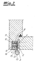
- the tape receiving element 1 according to the invention is shown in the mounted state in FIG.
- a hinge flap 12 is fixed between the clamping plate 3 and the clamping plate 4 by the clamping screws 11.
- the clamping plate 3 can be moved by adjusting the position of the clamping plate 4 to the cover plate 7, so that door hinges with straight hinge tabs 12 and narrow tape rolls 13 can be used with a diameter of for example 15 mm.
- the cover plate 7 has an angled in the direction of the depth of the tape receiving element area 14, in which a frame-shaped recess 15 is provided for the implementation of the hinge strap 12. Die Verschlußplatte 14 ist mit dem Bandlappen 12 ownership.
- the cover 7 includes both front and in its angled portion 14 flush with the profile of the door frame.
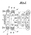
- FIG. 3 The structure of a possible embodiment of the tape receiving element according to the invention is shown in Fig. 3 in an exploded view.
- the rear part of the carrier 5 has holes 16 in which the adjusting spindles 10 are mounted.
- Front side, the adjusting spindles 10 are mounted in the two front panels 6, wherein the front panels 6 are permanently connected with rivets to the vertical end portions of the bow-shaped support 5.
- the adjusting spindles 10 are received by the clamping plate 4, which is arranged by the adjusting spindles 10 along its longitudinal axis adjustable between the front plate assembly 2 and the carrier 5.
- the clamping plate 3 is penetrated by clamping screws 11, which engage in threaded bores of the clamping plate 4.
- the rear part of the support 5 bores 17 whose diameter is greater than the diameter of the thread of the clamping screws 11.
- the cover plate 7 has an angled in the direction of the depth of the tape receiving member portion 14 with a frame-shaped recess 15 for the implementation of the tape tab on.
- the adjusting spindles 10, which are mounted in the front plates 6, and the clamping screws 11 are accessible through holes in the cover plate 7.
- the tape receiving element can be fastened by bores 18, 18 'in the cover plate 7 and the front plates 6 to the block or feed frame.
- the holes 18 'in the front panels 6 each have a recess and the associated holes 18 of the cover plate 7 each have an edge-side impression for receiving the head of a fastening screw, which ensures that the fastening screw after assembly of the tape receiving element to the block or Feed frame does not protrude from the cover plate 7.
- the cover plate 7 has a surface-finished and polished outer surface, which is adapted to the surface finish of a mounted on the tape receiving element door hinge.
- the front panels 6 are permanently connected by gluing or welding with the cover plate 7.
- the front panel assembly 2 formed from the two front panels 6 and the cover panel 7 is placed on the vertical end portions of the bow-shaped support 5, wherein the adjusting spindles 10 engage in the front panel assembly 2.
- they are fixed in the carrier 5 by riveting rotatably.
Landscapes
- Engineering & Computer Science (AREA)
- Mechanical Engineering (AREA)
- Hinges (AREA)
- Securing Of Glass Panes Or The Like (AREA)
Abstract
Description
- Die Erfindung betrifft ein Bandaufnahmeelement für Block- und Futterzargen mit einer Frontplattenanordnung, einer Klemmplatte, einer Spannplatte und einem Träger, wobei die Klemmplatte von Klemmschrauben durchgriffen wird, die in Gewindebohrungen der Spannplatte eingreifen und mit denen die Klemmplatte zur Aufnahme eines Bandlappens gegen die Spannplatte verstellbar ist, und wobei die Spannplatte Stellspindeln aufnimmt, die jeweils in der Frontplattenanordnung und dem Träger gelagert sind und mit denen die Position der Spannplatte entlang der Stellspindeln einstellbar ist.
- Ein Bandaufnahmeelement für Block- und Futterzargen mit den eingangs beschriebenen Merkmalen ist aus
DE 20 2004 016 909 U1 bekannt. Die Frontplattenanordnung ist als einteilige, nicht abgewinkelte Frontplatte ausgebildet, die eine nach vorne offene Ausnehmung aufweist, durch die die Klemmplatte beim Verstellen gerade hindurchpasst und nach vorne übersteht. Bedingt durch den Aufbau des Bandaufnahmeelementes ist stets ein Spalt und üblicherweise auch ein Versatz in Richtung der Tiefe des Bandaufnahmeelementes zwischen Klemmplatte und Frontplatte sichtbar. Auch ist der Bereich, in dem der Bandlappen seitlich in das Bandaufnahmeelement eingesteckt wird, nicht abgedeckt und so im montierten Zustand von der Seite einsehbar. Aus den genannten Gründen ist das beschriebene Bandaufnahmeelement aus gestaltungstechnischer Sicht unbefriedigend, wobei die Kanten und Ritzen auch einer erhöhten Verschmutzung ausgesetzt und schwer zu reinigen sind. - Vor diesem Hintergrund liegt der Erfindung die Aufgabe zugrunde, ein Bandaufnahmeelement anzugeben, welches ein ansprechendes und bei der Fertigung leicht veränderbares Aussehen aufweist und für die Aufnahme von Türbändern mit einem kleinen Rollendurchmesser und mit gerade verlaufenden Bandlappen geeignet ist.
- Die Aufgabe wird erfindungsgemäß dadurch gelöst, dass die Frontplattenanordnung aus zwei Frontplatten und einem auf den Frontplatten angeordneten Abdeckblech gebildet ist, wobei ein Zwischenbereich zwischen den Frontplatten von dem Abdeckblech überbrückt ist, und dass die Klemmplatte durch Einstellen der Position der Spannplatte in den Zwischenbereich zwischen den Frontplatten einzubringen ist. Die Stabilität der Frontplattenanordnung wird maßgeblich von den zwei Frontplatten gewährleistet, die durch das Abdeckblech verdeckt und verbunden sind. Im montierten Zustand des Bandaufnahmeelementes ist im Wesentlichen nur das Abdeckblech sichtbar.
- Als Abdeckblech eignet sich ein dünnes Blech, welches typischerweise eine Dicke von weniger als 1,5 mm, vorzugsweise weniger als 1 mm, aufweist und leicht und kostengünstig gefertigt werden kann. In einer bevorzugten Ausführung der Erfindung ist zumindest die Beschaffenheit der außen liegenden Oberfläche des Abdeckbleches an die Oberflächenbeschaffenheit eines an dem Bandaufnahmeelement montierten Türbandes angepasst. Dabei können beispielsweise die Farbe, die Oberflächentextur und/oder der Glanz an das gesamte Türband oder an Teile des Türbandes wie beispielsweise die Bandrolle oder den in dem Bandaufnahmeelement aufgenommenen Bandlappen angepasst werden. Da im montierten Zustand im Wesentlichen nur das Abdeckblech sichtbar ist, ist das Aussehen der weiteren Teile des Bandaufnahmeelementes unerheblich, und es können daher stets gleiche Standardteile verwendet werden.
- Vorzugsweise kann die Spannplatte durch die Stellspindeln so weit in Richtung der Frontplattenanordnung eingestellt werden, dass die in dem Zwischenbereich zwischen den Frontplatten angeordnete Klemmplatte an dem dünnen Abdeckblech anschlägt. Ein zwischen Klemmplatte und Spannplatte aufgenommener Bandlappen kann daher weit in Richtung der Außenseite des Bandaufnahmeelementes verstellt werden, wodurch der erfindungsgemäße Aufbau die Verwendung von Türbändern mit geraden Bandlappen und sehr schmalen Bandrollen, beispielsweise mit einem Durchmesser von 18 mm oder weniger, ermöglicht. Zur Maximierung des Stellwegs der Spannplatte können in dem Träger im Bereich der Klemmschrauben Bohrungen vorgesehen sein, deren Durchmesser größer ist als der Durchmesser der Gewinde der Klemmschrauben, so dass die möglicherweise nach hinten vorstehenden Enden der Klemmschraube sich nicht gegen den Träger verklemmen können.
- In einer bevorzugten Ausführung der Erfindung weist das Abdeckblech einen in Richtung der Tiefe des Bandaufnahmeelementes abgewinkelten Bereich auf, in dem eine rahmenförmige Ausnehmung für die Durchführung des Bandlappens vorgesehen ist. Dieser abgewinkelte Bereich deckt den seitlich sichtbaren Teil des Bandaufnahmeelementes, in den der Bandlappen eingeschoben ist, weitgehend ab und schützt das Bandaufnahmeelement zusätzlich vor Verschmutzung. Vorzugsweise weist das Abdeckblech Bohrungen auf, durch die die Klemmschrauben und die Stellspindeln zugänglich sind, wobei bei einer solchen Ausgestaltung die Stellspindeln in der Frontplatte gelagert sind. Bei einer solchen Ausgestaltung sind im montierten Zustand des Bandaufnahmeelementes die Klemmschrauben durch ein geeignetes Werkzeug zugänglich, so dass ein zwischen Klemmplatte und Spannplatte eingebrachter Bandlappen fixiert werden kann. Anschließend ist es dann möglich die Position des Bandlappens in Tiefenrichtung des Bandaufnahmeelementes durch eine Einstellung der Position der Spannplatte entlang der Stellspindeln einzustellen. Geeignet sind insbesondere Klemmschrauben und Stellspindeln, die mit einem Inbusschlüssel durch die Bohrungen in dem Abdeckblech hindurch zu betätigen sind.
- Zur Befestigung des Bandaufnahmeelementes an der Block- oder Futterzarge mit Befestigungsschrauben können Bohrungen im Abdeckblech und in den Frontplatten vorgesehen sein. Dabei kann durch Einsenkungen um die Bohrungen in der Frontplatte und randseitige Einprägungen um die zugeordneten Bohrungen des Abdeckbleches zur Aufnahme der Köpfe der Befestigungsschrauben gewährleistet werden, dass die Befestigungsschrauben nach der Montage des Bandaufnahmeelementes an der Block- oder Futterzarge nicht aus dem Abdeckblech vorstehen.
- Im Rahmen der Erfindung sind verschiedene Ausgestaltungen des erfindungsgemäßen Bandaufnahmeelementes möglich. In einer bevorzugten Ausführung der Erfindung ist der Träger bügelförmig mit in Richtung der Frontplattenanordnung vorstehenden vertikalen Endabschnitten ausgebildet. Bei einer solchen Ausgestaltung können die Frontplatten mit den vertikalen Endabschnitten des Trägers in direktem Kontakt stehen und mit diesen, vorzugsweise durch eine Vernietung, dauerhaft verbunden sein. Bei einer solchen Ausgestaltung sind die Teile des Bandaufnahmeelementes bis auf das Abdeckblech montagefertig zusammengefügt. Bei der Montage wird zusätzlich das Abdeckblech auf die vormontierten Teile des Bandaufnahmeelementes aufgebracht und mit dem Bandaufnahmeelement an der Block- oder Futterzarge befestigt. Besonders bei einer solchen Ausführung ist ein Austausch des Abdeckbleches, beispielsweise zur Anpassung an eine vorgegebene Beschaffenheit des Türbandes, sehr leicht möglich. So ist es auch denkbar, das Bandaufnahmeelement mit einem Satz verschiedenartiger Abdeckbleche vorzuhalten, wobei bei der Montage eines dieser Abdeckbleche entsprechend den Anforderungen auszuwählen ist.
- In einer alternativen Ausführung der Erfindung sind die Frontplatten, vorzugsweise durch Kleben oder Schweißen, mit dem Abdeckblech verbunden. Bei einer solchen Ausführung wird bei der Montage die gesamte Frontplattenanordnung auf die darunter liegenden Teile des Bandaufnahmeelementes aufgesetzt, wobei die Stellspindeln in frontplattenseitige Lagerungen eingebracht werden. Bei einer solchen Ausführung sind die Stellspindeln vorzugsweise in dem Träger durch Vernietung drehbeweglich fixiert. Eine solche drehbewegliche Fixierung ist jedoch auch ohne Einschränkung bei andersartigen Ausgestaltungen der Erfindung möglich.
- Zusätzlich zu den dargestellten Ausführungen der Erfindung ist es auch möglich, dass die Frontplatten vor der Montage weder mit dem Träger noch mit dem Abdeckblech verbunden sind und erst bei der Befestigung des Bandaufnahmeelementes an der Block- oder Futterzarge fixiert werden, Denkbar ist im Rahmen der Erfindung auch, dass das Abdeckblech eine geschlossene Oberfläche und einen in Richtung der Tiefe des Bandaufnahmeelementes abgewinkelten Bereich mit einer U-förmigen Ausnehmung für die Durchführung des Bandlappens aufweist, wobei das Abdeckblech durch eine Rastverbindung auf zumindest einem der darunter liegenden Teile des Bandaufnahmeelementes befestigt ist. Durch ein solches Abdeckblech, welches nach der Montage der weiteren Teile des Bandaufnahmeelementes an der Block- oder Futterzarge aufzustecken ist, ergeben sich weitere Gestaltungsmöglichkeiten, da die Befestigungsschrauben, die Klemmschrauben und die Stellspindel von dem Abdeckblech verdeckt werden.
- Im Folgenden wird die Erfindung anhand einer lediglich ein Ausführungsbeispiel darstellenden Zeichnung erläutert. Es zeigen schematisch:
- Fig. 1
- die Seitenansicht eines erfindungsgemäßen Bandaufnahmeelementes,
- Fig. 2
- einen horizontalen Schnitt durch ein in einer Blockzarge montiertes Bandaufnahmeelement mit einem daran über ein Türband befestigten Türflügel,
- Fig. 3
- eine Explosionsdarstellung der Teile eines erfindungsgemäßen Bandaufnahmeelementes,
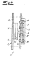
- Fig. 4
- die Seitenansicht einer alternativen Ausführung des erfindungsgemäßen Bandaufnahmeelementes.
- In Fig. 1 ist ein erfindungsgemäßes Bandaufnahmeelement 1 mit einer Frontplattenanordnung 2, einer Klemmplatte 3, einer Spannplatte 4 und einem Träger 5 dargestellt. Die Frontplattenanordnung 2 wird aus zwei Frontplatten 6 und einem auf den Frontplatten 6 angeordneten Abdeckblech 7 gebildet, welches einen Zwischenbereich 8 zwischen den Frontplatten 6 überbrückt. Die Frontplatten 6 liegen auf einem bügelförmigen Träger 5 mit in Richtung der Frontplattenanordnung 2 vorstehenden vertikalen Endabschnitten auf. Die Spannplatte 4 ist mit Stellspindeln 10, die in dem Träger 5 und den Frontplatten 6 gelagert sind, zwischen dem Träger 5 und der Frontplatenanordnung 2 verstellbar angeordnet. Die Klemmplatte 3 wird von Klemmschrauben 11 durchgriffen, die in Gewindebohrungen der Spannplatte 4 eingreifen und mit denen die Klemmplatte 3 zur Aufnahme eines Bandlappens gegen die Spannplatte 4 verstellbar ist. Durch Einstellen der Position der Spannplatte 4 kann die vor der Spannplatte 4 angeordnete Klemmplatte 3 in den Zwischenbereich 8 zwischen den Frontplatten 6 eingebracht werden.
- Das erfindungsgemäße Bandaufnahmeelement 1 ist im montierten Zustand in Fig. 2 dargestellt. Ein Bandlappen 12 ist zwischen der Klemmplatte 3 und der Spannplatte 4 durch die Klemmschrauben 11 fixiert. Die Klemmplatte 3 kann durch Einstellen der Position der Spannplatte 4 bis zum Abdeckblech 7 bewegt werden, so dass Türbänder mit geraden Bandlappen 12 und schmalen Bandrollen 13 mit einem Durchmesser von beispielsweise 15 mm eingesetzt werden können. Das Abdeckblech 7 weist einen in Richtung der Tiefe des Bandaufnahmeelementes abgewinkelten Bereich 14 auf, in dem eine rahmenförmige Ausnehmung 15 für die Durchführung des Bandlappens 12 vorgesehen ist. Das Abdeckblech 7 schließt sowohl frontseitig als auch in seinem abgewinkelten Bereich 14 bündig an das Profil der Türzarge an.
- Der Aufbau einer möglichen Ausführung des erfindungsgemäßen Bandaufnahmeelementes ist in Fig. 3 in einer Explosionszeichnung dargestellt. Der rückseitige Teil des Trägers 5 weist Bohrungen 16 auf, in denen die Stellspindeln 10 gelagert sind. Frontseitig sind die Stellspindeln 10 in den beiden Frontplatten 6 gelagert, wobei die Frontplatten 6 mit Nieten dauerhaft mit den vertikalen Endabschnitten des bügelförmigen Trägers 5 verbunden sind. Die Stellspindeln 10 sind von der Spannplatte 4 aufgenommen, die durch die Stellspindeln 10 entlang deren Längsachse verstellbar zwischen der Frontplattenanordnung 2 und dem Träger 5 angeordnet ist. Die Klemmplatte 3 wird von Klemmschrauben 11 durchgriffen, die in Gewindebohrungen der Spannplatte 4 eingreifen. In dem Bereich der Klemmschrauben 11 weist der rückseitige Teil des Trägers 5 Bohrungen 17 auf, deren Durchmesser größer ist als der Durchmesser der Gewinde der Klemmschrauben 11. Das Abdeckblech 7 weist einen in Richtung der Tiefe des Bandaufnahmeelementes abgewinkelten Bereich 14 mit einer rahmenförmigen Ausnehmung 15 für die Durchführung des Bandlappens auf. Die Stellspindeln 10, die in den Frontplatten 6 gelagert sind, und die Klemmschrauben 11 sind durch Bohrungen in dem Abdeckblech 7 zugänglich. Das Bandaufnahmeelement ist durch Bohrungen 18, 18' im Abdeckblech 7 und den Frontplatten 6 an der Block- oder Futterzarge befestigbar. Dabei weisen die Bohrungen 18' in den Frontplatten 6 jeweils eine Einsenkung und die zugeordneten Bohrungen 18 des Abdeckbleches 7 jeweils eine randseitige Einprägung zur Aufnahme des Kopfes einer Befestigungsschraube auf, wodurch gewährleistet wird, dass die Befestigungsschraube nach der Montage des Bandaufnahmeelementes an der Block- oder Futterzarge nicht aus dem Abdeckblech 7 vorsteht. Das Abdeckblech 7 weist eine oberflächenveredelte und polierte außen liegende Oberfläche auf, die an die Oberflächenbeschaffenheit eines an dem Bandaufnahmeelement montierten Türbandes angepasst ist.
- Die Fig. 4 zeigt das erfindungsgemäße Bandaufnahmeelement in einer alternativen Ausgestaltung. In der dargestellten Ausführung sind die Frontplatten 6 durch Kleben oder Schweißen dauerhaft mit dem Abdeckblech 7 verbunden. Bei der Montage des Türbandes wird die aus den zwei Frontplatten 6 und dem Abdeckblech 7 gebildete Frontplattenanordnung 2 auf die vertikalen Endabschnitte des bügelförmigen Trägers 5 aufgesetzt, wobei die Stellspindeln 10 in die Frontplattenanordnung 2 eingreifen. Um die Stellspindeln 10 vor dem Aufsetzen der Frontplattenanordnung 2 sicher in dem Träger 5 zu halten, sind diese in dem Träger 5 durch Vernietung drehbeweglich fixiert.
Claims (9)
- Bandaufnahmeelement für Block- und Futterzargen mit einer Frontplattenanordnung (2), einer Klemmplatte (3), einer Spannplatte (4) und einem Träger (5),
wobei die Klemmplatte (3) von Klemmschrauben (11) durchgriffen wird, die in Gewindebohrungen der Spannplatte (4) eingreifen und mit denen die Klemmplatte (3) zur Aufnahme eines Bandlappens gegen die Spannplatte (4) verstellbar ist, und
wobei die Spannplatte (4) Stellspindeln (10) aufnimmt, die jeweils in der Frontplattenanordnung (2) und dem Träger (5) gelagert sind und mit denen die Position der Spannplatte (4) entlang der Stellspindeln (10) einstellbar ist,
dadurch gekennzeichnet, dass die Frontplattenanordnung (2) aus zwei Frontplatten (6) und einem auf den Frontplatten (6) angeordneten Abdeckblech (7) gebildet ist, wobei ein Zwischenbereich (8) zwischen den Frontplatten (6) von dem Abdeckblech (7) überbrückt ist, und dass die Klemmplatte (3) durch Einstellen der Position der Spannplatte (4) in den Zwischenbereich (8) zwischen den Frontplatten (6) einzubringen ist. - Bandaufnahmeelement nach Anspruch 1, dadurch gekennzeichnet, dass das Abdeckblech (7) einen in Richtung der Tiefe des Bandaufnahmeelementes abgewinkelten Bereich (14) aufweist, in dem eine rahmenförmige Ausnehmung (15) für die Durchführung des Bandlappens vorgesehen ist.
- Bandaufnahmeelement nach Anspruch 1 oder 2, dadurch gekennzeichnet, dass die Beschaffenheit der außen liegenden Oberfläche des Abdeckbleches (7) an die Oberflächenbeschaffenheit eines an dem Bandaufnahmeelement montierten Türbandes angepasst ist.
- Bandaufnahmeelement nach einem der Ansprüche 1 bis 3, dadurch gekennzeichnet, dass die Stellspindeln (10) in den Frontplatten (6) gelagert sind und dass das Abdeckblech (7) Bohrungen aufweist, durch die die Klemmschrauben (11) und die Stellspindeln (10) zugänglich sind.
- Bandaufnahmeelement nach einem der Ansprüche 1 bis 4, dadurch gekennzeichnet, dass der Träger (5) bügelförmig mit in Richtung der Frontplattenanordnung (2) vorstehenden vertikalen Endabschnitten ausgebildet ist.
- Bandaufnahmeelement nach Anspruch 5, dadurch gekennzeichnet, dass die Frontplattenanordnung (2) mit den vertikalen Endabschnitten des Trägers (5) in direktem Kontakt steht und mit diesen, vorzugsweise durch eine Vemietung, dauerhaft verbunden ist.
- Bandaufnahmeelement nach einem der Ansprüche 1 bis 5, dadurch gekennzeichnet, dass die Frontplatten (6), vorzugsweise durch Kleben oder Schweißen, mit dem Abdeckblech (7) verbunden sind.
- Bandaufnahmeelement nach einem der Ansprüche 1 bis 7, dadurch gekennzeichnet, dass die Stellspindeln (10) in dem Träger (5) durch Vernietung drehbeweglich fixiert sind.
- Bandaufnahmeelement nach einem der Ansprüche 1 bis 8, dadurch gekennzeichnet, dass das Bandaufnahmeelement durch Bohrungen im Abdeckblech (7) und den Frontplatten (6) an der Block- oder Futterzarge befestigbar ist, wobei die Bohrungen in den Frontplatten (6) jeweils eine Einsenkung und die zugeordneten Bohrungen des Abdeckbleches (7) jeweils eine randseitige Einprägung zur Aufnahme des Kopfes einer Befestigungsschraube aufweisen, so dass die Befestigungsschrauben nach der Montage des Bandaufnahmeelementes an der Block- oder Futterzarge nicht aus dem Abdeckblech (7) vorstehen.
Priority Applications (1)
| Application Number | Priority Date | Filing Date | Title |
|---|---|---|---|
| PL06010029T PL1754849T3 (pl) | 2005-08-18 | 2006-05-16 | Element do mocowania zawiasu do ościeżnic blokowych i skrzynkowych |
Applications Claiming Priority (1)
| Application Number | Priority Date | Filing Date | Title |
|---|---|---|---|
| DE102005039037A DE102005039037B3 (de) | 2005-08-18 | 2005-08-18 | Bandaufnahmeelement für Block- und Futterzargen |
Publications (3)
| Publication Number | Publication Date |
|---|---|
| EP1754849A2 true EP1754849A2 (de) | 2007-02-21 |
| EP1754849A3 EP1754849A3 (de) | 2007-12-12 |
| EP1754849B1 EP1754849B1 (de) | 2012-10-10 |
Family
ID=36571406
Family Applications (1)
| Application Number | Title | Priority Date | Filing Date |
|---|---|---|---|
| EP06010029A Not-in-force EP1754849B1 (de) | 2005-08-18 | 2006-05-16 | Bandaufnahmeelement für Block- und Futterzargen |
Country Status (3)
| Country | Link |
|---|---|
| EP (1) | EP1754849B1 (de) |
| DE (1) | DE102005039037B3 (de) |
| PL (1) | PL1754849T3 (de) |
Cited By (1)
| Publication number | Priority date | Publication date | Assignee | Title |
|---|---|---|---|---|
| DE102012104863B3 (de) * | 2012-06-05 | 2012-12-20 | Simonswerk, Gesellschaft mit beschränkter Haftung | Türbandanordnung mit einem Türband und einem Aufnahmeelement |
Families Citing this family (5)
| Publication number | Priority date | Publication date | Assignee | Title |
|---|---|---|---|---|
| DE202006010505U1 (de) * | 2006-07-05 | 2007-11-15 | Dr. Hahn Gmbh & Co. Kg | Bandanordnung für Türen, Fenster o.dgl. |
| DE102007008963B3 (de) * | 2007-02-21 | 2008-03-06 | Stammschröer, Bernhard | Aufnahmeelement an Block- oder Futterzargen für einen Bandlappen eines Tür- oder Fensterbandes |
| DE102010011326B3 (de) * | 2010-03-13 | 2011-06-16 | Simonswerk, Gesellschaft mit beschränkter Haftung | Türband, insbesondere für Gebäudeabschlusstüren |
| DE102013106829B3 (de) * | 2013-06-28 | 2014-08-28 | Simonswerk, Gesellschaft mit beschränkter Haftung | Bandaufnahmeelement für Türbänder |
| DE202014102212U1 (de) | 2014-05-12 | 2014-05-21 | Simonswerk, Gesellschaft mit beschränkter Haftung | Türbandaufnahmeanordnung sowie Futterzargenanordnung |
Citations (1)
| Publication number | Priority date | Publication date | Assignee | Title |
|---|---|---|---|---|
| DE202004016909U1 (de) | 2004-11-03 | 2005-02-17 | Bartels Systembeschläge GmbH | Bandaufnahmeelement für Block- und Futterzargen |
Family Cites Families (4)
| Publication number | Priority date | Publication date | Assignee | Title |
|---|---|---|---|---|
| DE3932733C2 (de) * | 1989-09-30 | 1997-04-30 | Simonswerk Gmbh | Bandaufnahmeelement für Block- und Futterzargen aus Holz |
| DE19624558C1 (de) * | 1996-06-20 | 1997-07-31 | Bruynzeel Tueren Gmbh | Vorrichtung zur Befestigung von Bandlappen von Scharnieren an Stahlzargen |
| DE10347150B4 (de) * | 2003-03-20 | 2011-06-16 | Glutz Deutschland Gmbh | Unterkonstruktion |
| DE10336750A1 (de) * | 2003-08-08 | 2005-03-10 | Eco Schulte Gmbh & Co | Befestigungsvorrichtung für eine Bandaufnahme |
-
2005
- 2005-08-18 DE DE102005039037A patent/DE102005039037B3/de not_active Expired - Fee Related
-
2006
- 2006-05-16 PL PL06010029T patent/PL1754849T3/pl unknown
- 2006-05-16 EP EP06010029A patent/EP1754849B1/de not_active Not-in-force
Patent Citations (1)
| Publication number | Priority date | Publication date | Assignee | Title |
|---|---|---|---|---|
| DE202004016909U1 (de) | 2004-11-03 | 2005-02-17 | Bartels Systembeschläge GmbH | Bandaufnahmeelement für Block- und Futterzargen |
Cited By (1)
| Publication number | Priority date | Publication date | Assignee | Title |
|---|---|---|---|---|
| DE102012104863B3 (de) * | 2012-06-05 | 2012-12-20 | Simonswerk, Gesellschaft mit beschränkter Haftung | Türbandanordnung mit einem Türband und einem Aufnahmeelement |
Also Published As
| Publication number | Publication date |
|---|---|
| DE102005039037B3 (de) | 2006-06-22 |
| EP1754849B1 (de) | 2012-10-10 |
| PL1754849T3 (pl) | 2013-03-29 |
| EP1754849A3 (de) | 2007-12-12 |
Similar Documents
| Publication | Publication Date | Title |
|---|---|---|
| DE102005022042B3 (de) | Mehrdimensional verstellbares Türband an einem Türflügel | |
| EP1754849B1 (de) | Bandaufnahmeelement für Block- und Futterzargen | |
| DE202013101487U1 (de) | Drehtür-Baugruppe | |
| EP2366857B1 (de) | Befestigungsanordnung für eine Schiebetür | |
| EP1520955B1 (de) | Klemmträger für Sonnen- und Blickschutzeinrichtungen | |
| DE102011056056B3 (de) | Tür und Türband | |
| EP2570580A2 (de) | Dichtung für Türen, Fenster oder Ähnlichem mit einer absenkbaren Dichtleiste | |
| DE102004026270B4 (de) | Vorsatztür oder -fenster, insbesondere Insektenschutztür oder -fenster | |
| DE202007011076U1 (de) | Bandanordnung mit Führungsprofil | |
| DE102012104863B3 (de) | Türbandanordnung mit einem Türband und einem Aufnahmeelement | |
| EP1344478B1 (de) | Duschkabine mit einer wenigstens eine Glasplatte aufweisenden Duschtrennwand | |
| CH697365B1 (de) | Mehrdimensional verstellbares Türband. | |
| DE202005004124U1 (de) | Modulares, multifunktionales Beschlagsystem für Duschabtrennungen | |
| DE102007025857A1 (de) | Gelenkband für Türen oder Fenster | |
| DE102006030783B4 (de) | Rahmenlose Trennwand, mit einem Oberlicht und mit einem justierbaren Montageprofil zur Montage an einer ortsfesten Zarge | |
| DE202008016071U1 (de) | Band zur scharniergelenkigen Verbindung eines Flügels an einem Rahmen | |
| EP1589170A2 (de) | Modulares, multifunktionales Beschlagsystem für Duschabtrennungen | |
| DE19514867C2 (de) | Scharnier für Fenster, Türen od. dgl., insbesondere für Dreh-Kippbeschläge mit einer Ausstellvorrichtung | |
| EP2540942B1 (de) | Verstellbare Beschlagsanordnung | |
| EP1316276A1 (de) | Beschichtete Frontplatte für ein Küchenmöbel | |
| DE102011008765A1 (de) | Profilanordnung, Rahmen und Rahmenanordnung | |
| EP1703057B1 (de) | Klappenanordnung mit einer Klappe und einem Klappenscharnier | |
| EP1688570B1 (de) | Band für Türen, Fenster oder dergleichen | |
| DE202010000749U1 (de) | Klemmhalterung mit abgewinkelter Montagefläche | |
| DE202004016909U1 (de) | Bandaufnahmeelement für Block- und Futterzargen |
Legal Events
| Date | Code | Title | Description |
|---|---|---|---|
| PUAI | Public reference made under article 153(3) epc to a published international application that has entered the european phase |
Free format text: ORIGINAL CODE: 0009012 |
|
| AK | Designated contracting states |
Kind code of ref document: A2 Designated state(s): AT BE BG CH CY CZ DE DK EE ES FI FR GB GR HU IE IS IT LI LT LU LV MC NL PL PT RO SE SI SK TR |
|
| AX | Request for extension of the european patent |
Extension state: AL BA HR MK YU |
|
| PUAL | Search report despatched |
Free format text: ORIGINAL CODE: 0009013 |
|
| AK | Designated contracting states |
Kind code of ref document: A3 Designated state(s): AT BE BG CH CY CZ DE DK EE ES FI FR GB GR HU IE IS IT LI LT LU LV MC NL PL PT RO SE SI SK TR |
|
| AX | Request for extension of the european patent |
Extension state: AL BA HR MK YU |
|
| 17P | Request for examination filed |
Effective date: 20080422 |
|
| 17Q | First examination report despatched |
Effective date: 20080521 |
|
| AKX | Designation fees paid |
Designated state(s): AT BE BG CH CY CZ DE DK EE ES FI FR GB GR HU IE IS IT LI LT LU LV MC NL PL PT RO SE SI SK TR |
|
| REG | Reference to a national code |
Ref country code: DE Ref legal event code: R079 Ref document number: 502006012065 Country of ref document: DE Free format text: PREVIOUS MAIN CLASS: E05D0007040000 Ipc: E05D0011000000 |
|
| GRAP | Despatch of communication of intention to grant a patent |
Free format text: ORIGINAL CODE: EPIDOSNIGR1 |
|
| RIC1 | Information provided on ipc code assigned before grant |
Ipc: E05D 7/04 20060101ALI20120502BHEP Ipc: E05D 11/00 20060101AFI20120502BHEP |
|
| GRAS | Grant fee paid |
Free format text: ORIGINAL CODE: EPIDOSNIGR3 |
|
| GRAA | (expected) grant |
Free format text: ORIGINAL CODE: 0009210 |
|
| AK | Designated contracting states |
Kind code of ref document: B1 Designated state(s): AT BE BG CH CY CZ DE DK EE ES FI FR GB GR HU IE IS IT LI LT LU LV MC NL PL PT RO SE SI SK TR |
|
| REG | Reference to a national code |
Ref country code: GB Ref legal event code: FG4D Free format text: NOT ENGLISH |
|
| REG | Reference to a national code |
Ref country code: CH Ref legal event code: EP Ref country code: AT Ref legal event code: REF Ref document number: 579068 Country of ref document: AT Kind code of ref document: T Effective date: 20121015 |
|
| REG | Reference to a national code |
Ref country code: CH Ref legal event code: NV Representative=s name: KELLER & PARTNER PATENTANWAELTE AG |
|
| REG | Reference to a national code |
Ref country code: IE Ref legal event code: FG4D Free format text: LANGUAGE OF EP DOCUMENT: GERMAN |
|
| REG | Reference to a national code |
Ref country code: DE Ref legal event code: R096 Ref document number: 502006012065 Country of ref document: DE Effective date: 20121213 |
|
| REG | Reference to a national code |
Ref country code: NL Ref legal event code: T3 |
|
| PG25 | Lapsed in a contracting state [announced via postgrant information from national office to epo] |
Ref country code: SI Free format text: LAPSE BECAUSE OF FAILURE TO SUBMIT A TRANSLATION OF THE DESCRIPTION OR TO PAY THE FEE WITHIN THE PRESCRIBED TIME-LIMIT Effective date: 20121010 |
|
| REG | Reference to a national code |
Ref country code: LT Ref legal event code: MG4D |
|
| REG | Reference to a national code |
Ref country code: PL Ref legal event code: T3 |
|
| PG25 | Lapsed in a contracting state [announced via postgrant information from national office to epo] |
Ref country code: SE Free format text: LAPSE BECAUSE OF FAILURE TO SUBMIT A TRANSLATION OF THE DESCRIPTION OR TO PAY THE FEE WITHIN THE PRESCRIBED TIME-LIMIT Effective date: 20121010 Ref country code: ES Free format text: LAPSE BECAUSE OF FAILURE TO SUBMIT A TRANSLATION OF THE DESCRIPTION OR TO PAY THE FEE WITHIN THE PRESCRIBED TIME-LIMIT Effective date: 20130121 Ref country code: LT Free format text: LAPSE BECAUSE OF FAILURE TO SUBMIT A TRANSLATION OF THE DESCRIPTION OR TO PAY THE FEE WITHIN THE PRESCRIBED TIME-LIMIT Effective date: 20121010 Ref country code: FI Free format text: LAPSE BECAUSE OF FAILURE TO SUBMIT A TRANSLATION OF THE DESCRIPTION OR TO PAY THE FEE WITHIN THE PRESCRIBED TIME-LIMIT Effective date: 20121010 Ref country code: IS Free format text: LAPSE BECAUSE OF FAILURE TO SUBMIT A TRANSLATION OF THE DESCRIPTION OR TO PAY THE FEE WITHIN THE PRESCRIBED TIME-LIMIT Effective date: 20130210 |
|
| PG25 | Lapsed in a contracting state [announced via postgrant information from national office to epo] |
Ref country code: GR Free format text: LAPSE BECAUSE OF FAILURE TO SUBMIT A TRANSLATION OF THE DESCRIPTION OR TO PAY THE FEE WITHIN THE PRESCRIBED TIME-LIMIT Effective date: 20130111 Ref country code: LV Free format text: LAPSE BECAUSE OF FAILURE TO SUBMIT A TRANSLATION OF THE DESCRIPTION OR TO PAY THE FEE WITHIN THE PRESCRIBED TIME-LIMIT Effective date: 20121010 Ref country code: PT Free format text: LAPSE BECAUSE OF FAILURE TO SUBMIT A TRANSLATION OF THE DESCRIPTION OR TO PAY THE FEE WITHIN THE PRESCRIBED TIME-LIMIT Effective date: 20130211 Ref country code: CY Free format text: LAPSE BECAUSE OF FAILURE TO SUBMIT A TRANSLATION OF THE DESCRIPTION OR TO PAY THE FEE WITHIN THE PRESCRIBED TIME-LIMIT Effective date: 20121010 |
|
| PG25 | Lapsed in a contracting state [announced via postgrant information from national office to epo] |
Ref country code: BG Free format text: LAPSE BECAUSE OF FAILURE TO SUBMIT A TRANSLATION OF THE DESCRIPTION OR TO PAY THE FEE WITHIN THE PRESCRIBED TIME-LIMIT Effective date: 20130110 Ref country code: EE Free format text: LAPSE BECAUSE OF FAILURE TO SUBMIT A TRANSLATION OF THE DESCRIPTION OR TO PAY THE FEE WITHIN THE PRESCRIBED TIME-LIMIT Effective date: 20121010 Ref country code: SK Free format text: LAPSE BECAUSE OF FAILURE TO SUBMIT A TRANSLATION OF THE DESCRIPTION OR TO PAY THE FEE WITHIN THE PRESCRIBED TIME-LIMIT Effective date: 20121010 Ref country code: DK Free format text: LAPSE BECAUSE OF FAILURE TO SUBMIT A TRANSLATION OF THE DESCRIPTION OR TO PAY THE FEE WITHIN THE PRESCRIBED TIME-LIMIT Effective date: 20121010 |
|
| PLBE | No opposition filed within time limit |
Free format text: ORIGINAL CODE: 0009261 |
|
| STAA | Information on the status of an ep patent application or granted ep patent |
Free format text: STATUS: NO OPPOSITION FILED WITHIN TIME LIMIT |
|
| PG25 | Lapsed in a contracting state [announced via postgrant information from national office to epo] |
Ref country code: RO Free format text: LAPSE BECAUSE OF FAILURE TO SUBMIT A TRANSLATION OF THE DESCRIPTION OR TO PAY THE FEE WITHIN THE PRESCRIBED TIME-LIMIT Effective date: 20121010 |
|
| 26N | No opposition filed |
Effective date: 20130711 |
|
| REG | Reference to a national code |
Ref country code: DE Ref legal event code: R097 Ref document number: 502006012065 Country of ref document: DE Effective date: 20130711 |
|
| PG25 | Lapsed in a contracting state [announced via postgrant information from national office to epo] |
Ref country code: MC Free format text: LAPSE BECAUSE OF FAILURE TO SUBMIT A TRANSLATION OF THE DESCRIPTION OR TO PAY THE FEE WITHIN THE PRESCRIBED TIME-LIMIT Effective date: 20121010 |
|
| REG | Reference to a national code |
Ref country code: IE Ref legal event code: MM4A |
|
| REG | Reference to a national code |
Ref country code: FR Ref legal event code: ST Effective date: 20140131 |
|
| PG25 | Lapsed in a contracting state [announced via postgrant information from national office to epo] |
Ref country code: IE Free format text: LAPSE BECAUSE OF NON-PAYMENT OF DUE FEES Effective date: 20130516 |
|
| PG25 | Lapsed in a contracting state [announced via postgrant information from national office to epo] |
Ref country code: FR Free format text: LAPSE BECAUSE OF NON-PAYMENT OF DUE FEES Effective date: 20130531 |
|
| REG | Reference to a national code |
Ref country code: CH Ref legal event code: PCAR Free format text: NEW ADDRESS: EIGERSTRASSE 2 POSTFACH, 3000 BERN 14 (CH) |
|
| PG25 | Lapsed in a contracting state [announced via postgrant information from national office to epo] |
Ref country code: TR Free format text: LAPSE BECAUSE OF FAILURE TO SUBMIT A TRANSLATION OF THE DESCRIPTION OR TO PAY THE FEE WITHIN THE PRESCRIBED TIME-LIMIT Effective date: 20121010 |
|
| PG25 | Lapsed in a contracting state [announced via postgrant information from national office to epo] |
Ref country code: LU Free format text: LAPSE BECAUSE OF NON-PAYMENT OF DUE FEES Effective date: 20130516 Ref country code: HU Free format text: LAPSE BECAUSE OF FAILURE TO SUBMIT A TRANSLATION OF THE DESCRIPTION OR TO PAY THE FEE WITHIN THE PRESCRIBED TIME-LIMIT; INVALID AB INITIO Effective date: 20060516 |
|
| PGFP | Annual fee paid to national office [announced via postgrant information from national office to epo] |
Ref country code: CH Payment date: 20180523 Year of fee payment: 13 Ref country code: CZ Payment date: 20180514 Year of fee payment: 13 |
|
| PGFP | Annual fee paid to national office [announced via postgrant information from national office to epo] |
Ref country code: BE Payment date: 20180518 Year of fee payment: 13 Ref country code: NL Payment date: 20180518 Year of fee payment: 13 Ref country code: AT Payment date: 20180522 Year of fee payment: 13 Ref country code: PL Payment date: 20180423 Year of fee payment: 13 Ref country code: IT Payment date: 20180530 Year of fee payment: 13 |
|
| PGFP | Annual fee paid to national office [announced via postgrant information from national office to epo] |
Ref country code: GB Payment date: 20180518 Year of fee payment: 13 |
|
| PGFP | Annual fee paid to national office [announced via postgrant information from national office to epo] |
Ref country code: DE Payment date: 20190508 Year of fee payment: 14 |
|
| REG | Reference to a national code |
Ref country code: CH Ref legal event code: PL |
|
| REG | Reference to a national code |
Ref country code: NL Ref legal event code: MM Effective date: 20190601 |
|
| REG | Reference to a national code |
Ref country code: AT Ref legal event code: MM01 Ref document number: 579068 Country of ref document: AT Kind code of ref document: T Effective date: 20190516 |
|
| GBPC | Gb: european patent ceased through non-payment of renewal fee |
Effective date: 20190516 |
|
| PG25 | Lapsed in a contracting state [announced via postgrant information from national office to epo] |
Ref country code: CZ Free format text: LAPSE BECAUSE OF NON-PAYMENT OF DUE FEES Effective date: 20190516 Ref country code: LI Free format text: LAPSE BECAUSE OF NON-PAYMENT OF DUE FEES Effective date: 20190531 Ref country code: CH Free format text: LAPSE BECAUSE OF NON-PAYMENT OF DUE FEES Effective date: 20190531 Ref country code: AT Free format text: LAPSE BECAUSE OF NON-PAYMENT OF DUE FEES Effective date: 20190516 |
|
| REG | Reference to a national code |
Ref country code: BE Ref legal event code: MM Effective date: 20190531 |
|
| PG25 | Lapsed in a contracting state [announced via postgrant information from national office to epo] |
Ref country code: GB Free format text: LAPSE BECAUSE OF NON-PAYMENT OF DUE FEES Effective date: 20190516 Ref country code: NL Free format text: LAPSE BECAUSE OF NON-PAYMENT OF DUE FEES Effective date: 20190601 Ref country code: IT Free format text: LAPSE BECAUSE OF NON-PAYMENT OF DUE FEES Effective date: 20190516 |
|
| PG25 | Lapsed in a contracting state [announced via postgrant information from national office to epo] |
Ref country code: BE Free format text: LAPSE BECAUSE OF NON-PAYMENT OF DUE FEES Effective date: 20190531 |
|
| REG | Reference to a national code |
Ref country code: DE Ref legal event code: R119 Ref document number: 502006012065 Country of ref document: DE |
|
| PG25 | Lapsed in a contracting state [announced via postgrant information from national office to epo] |
Ref country code: DE Free format text: LAPSE BECAUSE OF NON-PAYMENT OF DUE FEES Effective date: 20201201 |
|
| PG25 | Lapsed in a contracting state [announced via postgrant information from national office to epo] |
Ref country code: PL Free format text: LAPSE BECAUSE OF NON-PAYMENT OF DUE FEES Effective date: 20190516 |