EP1741998A2 - Condenseur - Google Patents
Condenseur Download PDFInfo
- Publication number
- EP1741998A2 EP1741998A2 EP06021990A EP06021990A EP1741998A2 EP 1741998 A2 EP1741998 A2 EP 1741998A2 EP 06021990 A EP06021990 A EP 06021990A EP 06021990 A EP06021990 A EP 06021990A EP 1741998 A2 EP1741998 A2 EP 1741998A2
- Authority
- EP
- European Patent Office
- Prior art keywords
- collector
- condenser
- inlet
- transfer line
- refrigerant
- Prior art date
- Legal status (The legal status is an assumption and is not a legal conclusion. Google has not performed a legal analysis and makes no representation as to the accuracy of the status listed.)
- Granted
Links
- 239000003507 refrigerant Substances 0.000 claims description 27
- 239000003990 capacitor Substances 0.000 claims description 5
- 238000005192 partition Methods 0.000 claims description 4
- 238000004378 air conditioning Methods 0.000 claims description 3
- 238000009434 installation Methods 0.000 claims description 2
- 239000012530 fluid Substances 0.000 claims 1
- 238000001816 cooling Methods 0.000 abstract description 3
- 238000000926 separation method Methods 0.000 abstract description 3
- 239000002274 desiccant Substances 0.000 description 3
- 239000007788 liquid Substances 0.000 description 2
- 239000002245 particle Substances 0.000 description 2
- 238000001035 drying Methods 0.000 description 1
- 230000002349 favourable effect Effects 0.000 description 1
- 230000001771 impaired effect Effects 0.000 description 1
- 229910000679 solder Inorganic materials 0.000 description 1
- 238000011144 upstream manufacturing Methods 0.000 description 1
- XLYOFNOQVPJJNP-UHFFFAOYSA-N water Substances O XLYOFNOQVPJJNP-UHFFFAOYSA-N 0.000 description 1
Images


Classifications
-
- F—MECHANICAL ENGINEERING; LIGHTING; HEATING; WEAPONS; BLASTING
- F25—REFRIGERATION OR COOLING; COMBINED HEATING AND REFRIGERATION SYSTEMS; HEAT PUMP SYSTEMS; MANUFACTURE OR STORAGE OF ICE; LIQUEFACTION SOLIDIFICATION OF GASES
- F25B—REFRIGERATION MACHINES, PLANTS OR SYSTEMS; COMBINED HEATING AND REFRIGERATION SYSTEMS; HEAT PUMP SYSTEMS
- F25B39/00—Evaporators; Condensers
- F25B39/04—Condensers
-
- F—MECHANICAL ENGINEERING; LIGHTING; HEATING; WEAPONS; BLASTING
- F28—HEAT EXCHANGE IN GENERAL
- F28D—HEAT-EXCHANGE APPARATUS, NOT PROVIDED FOR IN ANOTHER SUBCLASS, IN WHICH THE HEAT-EXCHANGE MEDIA DO NOT COME INTO DIRECT CONTACT
- F28D1/00—Heat-exchange apparatus having stationary conduit assemblies for one heat-exchange medium only, the media being in contact with different sides of the conduit wall, in which the other heat-exchange medium is a large body of fluid, e.g. domestic or motor car radiators
- F28D1/02—Heat-exchange apparatus having stationary conduit assemblies for one heat-exchange medium only, the media being in contact with different sides of the conduit wall, in which the other heat-exchange medium is a large body of fluid, e.g. domestic or motor car radiators with heat-exchange conduits immersed in the body of fluid
- F28D1/04—Heat-exchange apparatus having stationary conduit assemblies for one heat-exchange medium only, the media being in contact with different sides of the conduit wall, in which the other heat-exchange medium is a large body of fluid, e.g. domestic or motor car radiators with heat-exchange conduits immersed in the body of fluid with tubular conduits
- F28D1/053—Heat-exchange apparatus having stationary conduit assemblies for one heat-exchange medium only, the media being in contact with different sides of the conduit wall, in which the other heat-exchange medium is a large body of fluid, e.g. domestic or motor car radiators with heat-exchange conduits immersed in the body of fluid with tubular conduits the conduits being straight
- F28D1/0535—Heat-exchange apparatus having stationary conduit assemblies for one heat-exchange medium only, the media being in contact with different sides of the conduit wall, in which the other heat-exchange medium is a large body of fluid, e.g. domestic or motor car radiators with heat-exchange conduits immersed in the body of fluid with tubular conduits the conduits being straight the conduits having a non-circular cross-section
- F28D1/05366—Assemblies of conduits connected to common headers, e.g. core type radiators
- F28D1/05375—Assemblies of conduits connected to common headers, e.g. core type radiators with particular pattern of flow, e.g. change of flow direction
-
- F—MECHANICAL ENGINEERING; LIGHTING; HEATING; WEAPONS; BLASTING
- F25—REFRIGERATION OR COOLING; COMBINED HEATING AND REFRIGERATION SYSTEMS; HEAT PUMP SYSTEMS; MANUFACTURE OR STORAGE OF ICE; LIQUEFACTION SOLIDIFICATION OF GASES
- F25B—REFRIGERATION MACHINES, PLANTS OR SYSTEMS; COMBINED HEATING AND REFRIGERATION SYSTEMS; HEAT PUMP SYSTEMS
- F25B2339/00—Details of evaporators; Details of condensers
- F25B2339/04—Details of condensers
- F25B2339/044—Condensers with an integrated receiver
- F25B2339/0441—Condensers with an integrated receiver containing a drier or a filter
-
- F—MECHANICAL ENGINEERING; LIGHTING; HEATING; WEAPONS; BLASTING
- F25—REFRIGERATION OR COOLING; COMBINED HEATING AND REFRIGERATION SYSTEMS; HEAT PUMP SYSTEMS; MANUFACTURE OR STORAGE OF ICE; LIQUEFACTION SOLIDIFICATION OF GASES
- F25B—REFRIGERATION MACHINES, PLANTS OR SYSTEMS; COMBINED HEATING AND REFRIGERATION SYSTEMS; HEAT PUMP SYSTEMS
- F25B2339/00—Details of evaporators; Details of condensers
- F25B2339/04—Details of condensers
- F25B2339/044—Condensers with an integrated receiver
- F25B2339/0443—Condensers with an integrated receiver the receiver being positioned horizontally
-
- F—MECHANICAL ENGINEERING; LIGHTING; HEATING; WEAPONS; BLASTING
- F25—REFRIGERATION OR COOLING; COMBINED HEATING AND REFRIGERATION SYSTEMS; HEAT PUMP SYSTEMS; MANUFACTURE OR STORAGE OF ICE; LIQUEFACTION SOLIDIFICATION OF GASES
- F25B—REFRIGERATION MACHINES, PLANTS OR SYSTEMS; COMBINED HEATING AND REFRIGERATION SYSTEMS; HEAT PUMP SYSTEMS
- F25B40/00—Subcoolers, desuperheaters or superheaters
- F25B40/02—Subcoolers
-
- F—MECHANICAL ENGINEERING; LIGHTING; HEATING; WEAPONS; BLASTING
- F28—HEAT EXCHANGE IN GENERAL
- F28D—HEAT-EXCHANGE APPARATUS, NOT PROVIDED FOR IN ANOTHER SUBCLASS, IN WHICH THE HEAT-EXCHANGE MEDIA DO NOT COME INTO DIRECT CONTACT
- F28D21/00—Heat-exchange apparatus not covered by any of the groups F28D1/00 - F28D20/00
- F28D2021/0019—Other heat exchangers for particular applications; Heat exchange systems not otherwise provided for
- F28D2021/008—Other heat exchangers for particular applications; Heat exchange systems not otherwise provided for for vehicles
- F28D2021/0084—Condensers
Definitions
- the invention relates to a condenser for the air conditioning system of a motor vehicle, the tubes of which flow through the refrigerant in several stages, for which it has two manifolds, and has a collector connected to one of the manifolds via inlet and outlet openings between the stages, having an outer sheath.
- a condenser with vertically extending heat exchanger tubes is shown in FIG. 7 of the EP 769 666 A1 known.
- the headers are arranged horizontally.
- the collector runs parallel to the heat exchanger tubes of the condenser and is arranged vertically upright. The vertical position of the collector is favorable with respect to the separation therein between still gaseous and already liquefied refrigerant, and is therefore the most widespread.
- the heat exchanger tubes are horizontal and thus arranged the manifolds of the local condenser vertically.
- the collector is located horizontally parallel to the heat exchanger tubes, below the tube - fin block of the condenser.
- the collector is releasably connected via a soldered connection block to one of the manifolds.
- the collector has the function of separating gaseous and liquid refrigerants and of collecting a desiccant. This feature may not work as well in the JP publication as it is desired.
- the inventor has set itself the task of designing its condenser with a collector so that the separation function and / or drying function of the collector is improved.
- the collector has an inner jacket, the inner jacket and outer jacket being arranged coaxially with one another, so that a flow channel for the refrigerant is formed between the inner jacket and the outer jacket, wherein the one inlet or outlet opening communicates with the space enclosed by the inner jacket and the other inlet or outlet opening is arranged in the outer jacket.
- a dryer In the room, which is enclosed by the inner shell, there is a dryer and according to an embodiment, a filter.
- the filter is arranged above the dryer, wherein the cleaned refrigerant after flowing through the filter reverses its direction of flow and enters the said stage of the condenser via the flow channel and the other inlet or outlet opening.
- only the dryer is located in the space which is enclosed by the inner jacket, and that the filter is arranged in the flow path in front of the outflow opening.
- the other inlet or outlet opening of the collector is provided approximately at the front end of the collecting tube.
- Each stage consists of several parallel heat exchanger tubes of the condenser. Furthermore, the provision of the transfer line improves the position of the collector.
- the collector In Fig. 7 of the EP 769 666 A1 the collector is located in front of or behind the tube - fin block, so that the heat exchange between the cooling air flowing in perpendicular to the tube - fin block and the refrigerant flowing inside the tube - fin block is impaired.
- the collector is laterally adjacent to the tube-and-finned block, thereby improving the efficiency of heat exchange.
- the transfer line the refrigerant is transferred from one stage to the other via the other stage into the collector. After flowing through the collector the refrigerant enters the mentioned other stage and flows through it.
- This other stage may, for example, be a subcooling stage.
- the transfer line may be located either within the header or outside the header.
- the compactness is further improved when a transfer line disposed within the manifold is selected.
- This may be an approximately coaxial tube.
- the manifold could be divided in the transfer line but also only by a wall.
- the other inlet or outflow opening is preferably provided directly between the jacket of the collector and the front end of the collecting tube.
- the collector is located in the immediate vicinity of the tube - fin block, and in particular in the immediate vicinity and parallel to one of the side parts, which usually reinforce the tube - rib block on the sides. If necessary, an additional mounting of the collector can be provided on these side parts.
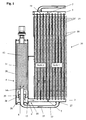
- FIGS. 1-4 show an exemplary embodiment with an external transfer line and with a filter located below the container.
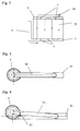
- FIGS. 5-8 show an exemplary embodiment with a transfer line integrated in the collecting tube and with a filter present in the container.
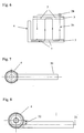
- Fig. 9 shows a flared manifold with integrated transfer line.
- stages 1 and 2 each consist of a plurality of flat heat exchanger tubes 15 , wherein between the heat exchanger tubes 15 corrugated fins 18 are arranged, which are flowed through by the cooling air to cool the refrigerant in the heat exchanger tubes 15 and to condense.
- the refrigerant leaves the condenser 30 in the fully liquefied and supercooled state.
- the sections of the condenser 30 shown in FIGS. 1 and 5 are therefore in the stage 1 by several stages, which are connected upstream, as can be seen in principle from FIGS. 2 and 6.
- the steps 1, 2 are formed by the appropriate arrangement of partitions 7 in the headers 3 and 5 .
- the refrigerant 25 enters the condenser 30 through the inlet and outlet flange 26 . It flows through several stages 1 before it enters the transfer line 10 through the inlet opening 27 . Through the transfer line 10 , the entire refrigerant 25 is guided past the stage 2 and transferred to the collector 4 .
- the transfer line 10 enters the collector 4 and passes through the space 28 , the filter 29 and above the filter 29, the liquid mixed with small amounts of gas refrigerant 25 via the inflow opening 14 into the interior of the collector 4 from.
- the desiccant is in a container 12th
- the refrigerant flows through the filter 29 to separate the smallest particles and into the return flow 28th
- the dividers 36 are to guarantee that the entire refrigerant 25 flows through the filter 29 .
- the refrigerant 25 leaves the collector 4 and flows through the front end 35 of the collecting tube 3 into the stage 2 of the condenser 30 .
- the subcooling in stage 2 After the subcooling in stage 2 , it passes via the collecting pipe 5 and the outlet 19 to the inlet and outlet flange 26, in order then to continue its travel in the air conditioning circuit (not shown). 4, an alternative to the first embodiment is shown. In some cases it may be necessary to place the collector 4 slightly in front of or behind the plane 33 of the tube-fin block of the condenser 30 . The collector 4 is then offset by the distance 32 from the plane 33 to the front or rear, but otherwise identical to the first embodiment.
- the refrigerant 25 enters the condenser 30 through the inlet and outlet flange 26 . It flows through several stages 1 before it enters the transfer line 10 through the inlet opening 27 . Through the transfer line 10 , the entire refrigerant 25 is passed to the stage 2 over and transferred to the collector 4 . At the flange 8 , the transfer line 10 enters the collector 4 a. The flange 8 is also the inflow opening 14 , through which the refrigerant 25 flows into an inner shell 20 . In the inner jacket 20 , the desiccant is in a container 12th On his way It happens to the above the dryer arranged filter 29 to separate the smallest particles.
- FIG. 8 also shows an alternative to the second exemplary embodiment. In some cases it may be necessary to place the collector 4 slightly in front of or behind the plane 33 of the tube - fin block of the condenser 1 . The collector 4 is then offset by the distance 32 from the plane 33 to the front or rear, but otherwise identical to the second embodiment.
- FIG. 9 an alternative embodiment of a transfer line is shown.
- the manifold 3 was enlarged on the collector 4 side facing 35 in diameter.
- the manifold 3 has been widened to accommodate the transfer line 10 so that the returning refrigerant 25 undergoes no unnecessary pressure loss through a too narrow manifold 3 .
- the installation of the transfer line 10 is easier to accomplish.
Landscapes
- Engineering & Computer Science (AREA)
- Physics & Mathematics (AREA)
- Mechanical Engineering (AREA)
- Thermal Sciences (AREA)
- General Engineering & Computer Science (AREA)
- Air-Conditioning For Vehicles (AREA)
- Heat-Exchange Devices With Radiators And Conduit Assemblies (AREA)
- Valve Device For Special Equipments (AREA)
- Oscillators With Electromechanical Resonators (AREA)
- Inverter Devices (AREA)
Applications Claiming Priority (2)
| Application Number | Priority Date | Filing Date | Title |
|---|---|---|---|
| DE10357176A DE10357176A1 (de) | 2003-12-06 | 2003-12-06 | Kondensator |
| EP04027603A EP1538407B1 (fr) | 2003-12-06 | 2004-11-20 | Condenseur |
Related Parent Applications (2)
| Application Number | Title | Priority Date | Filing Date |
|---|---|---|---|
| EP04027603.2 Division | 2004-11-20 | ||
| EP04027603A Division EP1538407B1 (fr) | 2003-12-06 | 2004-11-20 | Condenseur |
Publications (3)
| Publication Number | Publication Date |
|---|---|
| EP1741998A2 true EP1741998A2 (fr) | 2007-01-10 |
| EP1741998A3 EP1741998A3 (fr) | 2007-08-22 |
| EP1741998B1 EP1741998B1 (fr) | 2010-04-14 |
Family
ID=34442492
Family Applications (2)
| Application Number | Title | Priority Date | Filing Date |
|---|---|---|---|
| EP04027603A Expired - Lifetime EP1538407B1 (fr) | 2003-12-06 | 2004-11-20 | Condenseur |
| EP06021990A Expired - Lifetime EP1741998B1 (fr) | 2003-12-06 | 2004-11-20 | Condenseur |
Family Applications Before (1)
| Application Number | Title | Priority Date | Filing Date |
|---|---|---|---|
| EP04027603A Expired - Lifetime EP1538407B1 (fr) | 2003-12-06 | 2004-11-20 | Condenseur |
Country Status (4)
| Country | Link |
|---|---|
| US (1) | US6971251B2 (fr) |
| EP (2) | EP1538407B1 (fr) |
| AT (2) | ATE464518T1 (fr) |
| DE (3) | DE10357176A1 (fr) |
Families Citing this family (4)
| Publication number | Priority date | Publication date | Assignee | Title |
|---|---|---|---|---|
| FR2965336B1 (fr) | 2010-09-28 | 2012-09-14 | Valeo Systemes Thermiques | Ensemble d'un echangeur de chaleur biphasique et d'une bouteille |
| JP6216113B2 (ja) * | 2012-04-02 | 2017-10-18 | サンデンホールディングス株式会社 | 熱交換器及びそれを用いたヒートポンプシステム |
| JP6541219B2 (ja) | 2015-05-19 | 2019-07-10 | サンデン・オートモーティブクライメイトシステム株式会社 | 受液器付き熱交換器 |
| EP3855095B1 (fr) * | 2020-01-22 | 2023-08-23 | Valeo Autosystemy SP. Z.O.O. | Échangeur de chaleur comportant un dispositif de séchage de récepteur positionné horizontalement |
Citations (4)
| Publication number | Priority date | Publication date | Assignee | Title |
|---|---|---|---|---|
| EP0769666A1 (fr) | 1995-10-18 | 1997-04-23 | Calsonic Corporation | Condenseur avec un réservoir à liquide |
| US5937671A (en) | 1996-11-08 | 1999-08-17 | Zexel Corporation | Liquid tank |
| EP0974793A2 (fr) | 1998-07-23 | 2000-01-26 | Sanden Corporation | Condenseur équipé avec un bouteille accumulatrice |
| JP2001174103A (ja) | 1999-12-14 | 2001-06-29 | Denso Corp | 冷媒凝縮器 |
Family Cites Families (12)
| Publication number | Priority date | Publication date | Assignee | Title |
|---|---|---|---|---|
| JP2827404B2 (ja) * | 1989-04-28 | 1998-11-25 | 株式会社デンソー | 冷媒凝縮器 |
| JP3116996B2 (ja) * | 1996-10-30 | 2000-12-11 | 株式会社デンソー | 受液器一体型冷媒凝縮器 |
| US6304222B1 (en) * | 1997-12-22 | 2001-10-16 | Nortel Networks Limited | Radio communications handset antenna arrangements |
| JP4052706B2 (ja) * | 1998-01-22 | 2008-02-27 | 昭和電工株式会社 | サブクールシステムコンデンサ |
| JPH11270927A (ja) * | 1998-03-20 | 1999-10-05 | Zexel:Kk | 熱交換器の接続構造及び接続部材 |
| DE19926990B4 (de) * | 1998-06-16 | 2009-02-05 | Denso Corp., Kariya-shi | Mit integriertem Aufnahmebehälter ausgestatteter Kondensator für einen Kühl- bzw. Kältemittelzyklus |
| IT1304676B1 (it) * | 1998-10-06 | 2001-03-28 | Magneti Marelli Climat Srl | Condensatore per impianti di condizionamento d'aria di veicoli, aventeun accumulatore integrato ed una sezione di sottoraffreddamento. |
| EP1202007A1 (fr) * | 2000-10-25 | 2002-05-02 | Skg Italiana Spa | Condenseur et dessiccateur |
| JP2002187424A (ja) * | 2000-12-19 | 2002-07-02 | Denso Corp | 車両用凝縮器 |
| DE10213176A1 (de) * | 2002-03-23 | 2003-10-02 | Behr Gmbh & Co | Kältmittelkondensator |
| DE20208337U1 (de) * | 2002-05-28 | 2003-10-16 | Thermo King Deutschland GmbH, 68766 Hockenheim | Anordnung zum Klimatisieren eines Fahrzeugs |
| ITTO20030768A1 (it) * | 2003-10-02 | 2005-04-03 | Denso Thermal Systems Spa | Condensatore per veicoli e corpo integrato radiatore- |
-
2003
- 2003-12-06 DE DE10357176A patent/DE10357176A1/de not_active Withdrawn
-
2004
- 2004-11-20 EP EP04027603A patent/EP1538407B1/fr not_active Expired - Lifetime
- 2004-11-20 DE DE502004003826T patent/DE502004003826D1/de not_active Expired - Lifetime
- 2004-11-20 AT AT06021990T patent/ATE464518T1/de not_active IP Right Cessation
- 2004-11-20 DE DE502004011057T patent/DE502004011057D1/de not_active Expired - Lifetime
- 2004-11-20 EP EP06021990A patent/EP1741998B1/fr not_active Expired - Lifetime
- 2004-11-20 AT AT04027603T patent/ATE362601T1/de not_active IP Right Cessation
- 2004-12-06 US US11/006,172 patent/US6971251B2/en not_active Expired - Fee Related
Patent Citations (4)
| Publication number | Priority date | Publication date | Assignee | Title |
|---|---|---|---|---|
| EP0769666A1 (fr) | 1995-10-18 | 1997-04-23 | Calsonic Corporation | Condenseur avec un réservoir à liquide |
| US5937671A (en) | 1996-11-08 | 1999-08-17 | Zexel Corporation | Liquid tank |
| EP0974793A2 (fr) | 1998-07-23 | 2000-01-26 | Sanden Corporation | Condenseur équipé avec un bouteille accumulatrice |
| JP2001174103A (ja) | 1999-12-14 | 2001-06-29 | Denso Corp | 冷媒凝縮器 |
Also Published As
| Publication number | Publication date |
|---|---|
| ATE464518T1 (de) | 2010-04-15 |
| EP1538407A2 (fr) | 2005-06-08 |
| DE502004003826D1 (de) | 2007-06-28 |
| EP1538407B1 (fr) | 2007-05-16 |
| ATE362601T1 (de) | 2007-06-15 |
| EP1538407A3 (fr) | 2005-10-05 |
| DE502004011057D1 (de) | 2010-05-27 |
| US6971251B2 (en) | 2005-12-06 |
| US20050120739A1 (en) | 2005-06-09 |
| DE10357176A1 (de) | 2005-06-30 |
| EP1741998B1 (fr) | 2010-04-14 |
| EP1741998A3 (fr) | 2007-08-22 |
Similar Documents
| Publication | Publication Date | Title |
|---|---|---|
| DE4245046C5 (de) | Kondensator für eine Klimaanlage eines Fahrzeuges | |
| DE69611507T2 (de) | Verflüssiger mit einbezogenem behälter für klimaanlage eines kraftfahrzeuges | |
| DE10162200A1 (de) | Mit einem Aufnahmebehälter zusammengefasster Kondensator für ein Fahrzeug | |
| DE60102104T2 (de) | Wärmetauscher und Wärmetauscherrohr dafür | |
| DE112009001070T5 (de) | Kondensator | |
| DE10123347B4 (de) | Wärmeaustauscher mit Phasen-Änderung von Kältemittel | |
| DE112019003711T5 (de) | Integrierter Flüssigkeits-/Luftgekühlter Kondensator und Niedertemperatur-Kühler | |
| DE102011113453A1 (de) | Kühler | |
| WO2005038381A1 (fr) | Radiateur de liquide de refroidissement d'un vehicule automobile | |
| DE102017211736A1 (de) | Kondensator | |
| DE4330214B4 (de) | Wärmetauscher | |
| EP2606292B1 (fr) | Module de condenseur à réfrigérant | |
| DE60017969T2 (de) | Kondensator | |
| EP1741998B1 (fr) | Condenseur | |
| DE102007010530B4 (de) | Behälter für einen Wärmetauscher und Wärmetauscher | |
| DE102021213376A1 (de) | Wärmeübertrager und Kältemittelkreislauf mit einem Wärmeübertrager | |
| DE4213509A1 (de) | Wärmetauscher, insbesondere Kondensator für Fahrzeug-Klimaanlagen | |
| DE102004059680B4 (de) | Bauanordnung für Einrichtungen zum Austausch von Wärme | |
| DE20009332U1 (de) | Klimagerät für Personentransportfahrzeuge | |
| EP2108912B1 (fr) | Condenseur, en particulier pour système de climatisation de véhicules | |
| EP1310760B1 (fr) | Condenseur de fluide frigoporteur | |
| DE19957307A1 (de) | Zweikreis-Wärmeübertrager | |
| EP1684032B1 (fr) | Condenseur pour système de climatisation, en particulier pour véhicules | |
| DE102004028028A1 (de) | Wärmetauscher | |
| DE2831022A1 (de) | Waermetauscheranordnung |
Legal Events
| Date | Code | Title | Description |
|---|---|---|---|
| PUAI | Public reference made under article 153(3) epc to a published international application that has entered the european phase |
Free format text: ORIGINAL CODE: 0009012 |
|
| AC | Divisional application: reference to earlier application |
Ref document number: 1538407 Country of ref document: EP Kind code of ref document: P |
|
| AK | Designated contracting states |
Kind code of ref document: A2 Designated state(s): AT BE BG CH CY CZ DE DK EE ES FI FR GB GR HU IE IS IT LI LU MC NL PL PT RO SE SI SK TR |
|
| PUAL | Search report despatched |
Free format text: ORIGINAL CODE: 0009013 |
|
| AK | Designated contracting states |
Kind code of ref document: A3 Designated state(s): AT BE BG CH CY CZ DE DK EE ES FI FR GB GR HU IE IS IT LI LU MC NL PL PT RO SE SI SK TR |
|
| 17P | Request for examination filed |
Effective date: 20080222 |
|
| AKX | Designation fees paid |
Designated state(s): AT BE BG CH CY CZ DE DK EE ES FI FR GB GR HU IE IS IT LI LU MC NL PL PT RO SE SI SK TR |
|
| GRAP | Despatch of communication of intention to grant a patent |
Free format text: ORIGINAL CODE: EPIDOSNIGR1 |
|
| GRAS | Grant fee paid |
Free format text: ORIGINAL CODE: EPIDOSNIGR3 |
|
| GRAA | (expected) grant |
Free format text: ORIGINAL CODE: 0009210 |
|
| AC | Divisional application: reference to earlier application |
Ref document number: 1538407 Country of ref document: EP Kind code of ref document: P |
|
| AK | Designated contracting states |
Kind code of ref document: B1 Designated state(s): AT BE BG CH CY CZ DE DK EE ES FI FR GB GR HU IE IS IT LI LU MC NL PL PT RO SE SI SK TR |
|
| REG | Reference to a national code |
Ref country code: GB Ref legal event code: FG4D Free format text: NOT ENGLISH |
|
| REG | Reference to a national code |
Ref country code: CH Ref legal event code: EP |
|
| REG | Reference to a national code |
Ref country code: IE Ref legal event code: FG4D Free format text: LANGUAGE OF EP DOCUMENT: GERMAN |
|
| REF | Corresponds to: |
Ref document number: 502004011057 Country of ref document: DE Date of ref document: 20100527 Kind code of ref document: P |
|
| REG | Reference to a national code |
Ref country code: NL Ref legal event code: VDEP Effective date: 20100414 |
|
| PG25 | Lapsed in a contracting state [announced via postgrant information from national office to epo] |
Ref country code: NL Free format text: LAPSE BECAUSE OF FAILURE TO SUBMIT A TRANSLATION OF THE DESCRIPTION OR TO PAY THE FEE WITHIN THE PRESCRIBED TIME-LIMIT Effective date: 20100414 Ref country code: ES Free format text: LAPSE BECAUSE OF FAILURE TO SUBMIT A TRANSLATION OF THE DESCRIPTION OR TO PAY THE FEE WITHIN THE PRESCRIBED TIME-LIMIT Effective date: 20100725 Ref country code: SE Free format text: LAPSE BECAUSE OF FAILURE TO SUBMIT A TRANSLATION OF THE DESCRIPTION OR TO PAY THE FEE WITHIN THE PRESCRIBED TIME-LIMIT Effective date: 20100414 |
|
| REG | Reference to a national code |
Ref country code: IE Ref legal event code: FD4D |
|
| PG25 | Lapsed in a contracting state [announced via postgrant information from national office to epo] |
Ref country code: IS Free format text: LAPSE BECAUSE OF FAILURE TO SUBMIT A TRANSLATION OF THE DESCRIPTION OR TO PAY THE FEE WITHIN THE PRESCRIBED TIME-LIMIT Effective date: 20100814 Ref country code: SI Free format text: LAPSE BECAUSE OF FAILURE TO SUBMIT A TRANSLATION OF THE DESCRIPTION OR TO PAY THE FEE WITHIN THE PRESCRIBED TIME-LIMIT Effective date: 20100414 Ref country code: FI Free format text: LAPSE BECAUSE OF FAILURE TO SUBMIT A TRANSLATION OF THE DESCRIPTION OR TO PAY THE FEE WITHIN THE PRESCRIBED TIME-LIMIT Effective date: 20100414 |
|
| PG25 | Lapsed in a contracting state [announced via postgrant information from national office to epo] |
Ref country code: CY Free format text: LAPSE BECAUSE OF FAILURE TO SUBMIT A TRANSLATION OF THE DESCRIPTION OR TO PAY THE FEE WITHIN THE PRESCRIBED TIME-LIMIT Effective date: 20100505 Ref country code: GR Free format text: LAPSE BECAUSE OF FAILURE TO SUBMIT A TRANSLATION OF THE DESCRIPTION OR TO PAY THE FEE WITHIN THE PRESCRIBED TIME-LIMIT Effective date: 20100715 Ref country code: PL Free format text: LAPSE BECAUSE OF FAILURE TO SUBMIT A TRANSLATION OF THE DESCRIPTION OR TO PAY THE FEE WITHIN THE PRESCRIBED TIME-LIMIT Effective date: 20100414 |
|
| PG25 | Lapsed in a contracting state [announced via postgrant information from national office to epo] |
Ref country code: EE Free format text: LAPSE BECAUSE OF FAILURE TO SUBMIT A TRANSLATION OF THE DESCRIPTION OR TO PAY THE FEE WITHIN THE PRESCRIBED TIME-LIMIT Effective date: 20100414 Ref country code: DK Free format text: LAPSE BECAUSE OF FAILURE TO SUBMIT A TRANSLATION OF THE DESCRIPTION OR TO PAY THE FEE WITHIN THE PRESCRIBED TIME-LIMIT Effective date: 20100414 Ref country code: PT Free format text: LAPSE BECAUSE OF FAILURE TO SUBMIT A TRANSLATION OF THE DESCRIPTION OR TO PAY THE FEE WITHIN THE PRESCRIBED TIME-LIMIT Effective date: 20100816 Ref country code: IE Free format text: LAPSE BECAUSE OF FAILURE TO SUBMIT A TRANSLATION OF THE DESCRIPTION OR TO PAY THE FEE WITHIN THE PRESCRIBED TIME-LIMIT Effective date: 20100414 |
|
| PLBE | No opposition filed within time limit |
Free format text: ORIGINAL CODE: 0009261 |
|
| STAA | Information on the status of an ep patent application or granted ep patent |
Free format text: STATUS: NO OPPOSITION FILED WITHIN TIME LIMIT |
|
| PG25 | Lapsed in a contracting state [announced via postgrant information from national office to epo] |
Ref country code: SK Free format text: LAPSE BECAUSE OF FAILURE TO SUBMIT A TRANSLATION OF THE DESCRIPTION OR TO PAY THE FEE WITHIN THE PRESCRIBED TIME-LIMIT Effective date: 20100414 Ref country code: RO Free format text: LAPSE BECAUSE OF FAILURE TO SUBMIT A TRANSLATION OF THE DESCRIPTION OR TO PAY THE FEE WITHIN THE PRESCRIBED TIME-LIMIT Effective date: 20100414 Ref country code: CZ Free format text: LAPSE BECAUSE OF FAILURE TO SUBMIT A TRANSLATION OF THE DESCRIPTION OR TO PAY THE FEE WITHIN THE PRESCRIBED TIME-LIMIT Effective date: 20100414 |
|
| 26N | No opposition filed |
Effective date: 20110117 |
|
| PG25 | Lapsed in a contracting state [announced via postgrant information from national office to epo] |
Ref country code: IT Free format text: LAPSE BECAUSE OF FAILURE TO SUBMIT A TRANSLATION OF THE DESCRIPTION OR TO PAY THE FEE WITHIN THE PRESCRIBED TIME-LIMIT Effective date: 20100414 |
|
| BERE | Be: lapsed |
Owner name: MODINE MANUFACTURING CY Effective date: 20101130 |
|
| PG25 | Lapsed in a contracting state [announced via postgrant information from national office to epo] |
Ref country code: MC Free format text: LAPSE BECAUSE OF NON-PAYMENT OF DUE FEES Effective date: 20101130 |
|
| REG | Reference to a national code |
Ref country code: CH Ref legal event code: PL |
|
| PG25 | Lapsed in a contracting state [announced via postgrant information from national office to epo] |
Ref country code: CH Free format text: LAPSE BECAUSE OF NON-PAYMENT OF DUE FEES Effective date: 20101130 Ref country code: LI Free format text: LAPSE BECAUSE OF NON-PAYMENT OF DUE FEES Effective date: 20101130 |
|
| PG25 | Lapsed in a contracting state [announced via postgrant information from national office to epo] |
Ref country code: BE Free format text: LAPSE BECAUSE OF NON-PAYMENT OF DUE FEES Effective date: 20101130 |
|
| REG | Reference to a national code |
Ref country code: AT Ref legal event code: MM01 Ref document number: 464518 Country of ref document: AT Kind code of ref document: T Effective date: 20101120 |
|
| PG25 | Lapsed in a contracting state [announced via postgrant information from national office to epo] |
Ref country code: AT Free format text: LAPSE BECAUSE OF NON-PAYMENT OF DUE FEES Effective date: 20101120 |
|
| PG25 | Lapsed in a contracting state [announced via postgrant information from national office to epo] |
Ref country code: BG Free format text: LAPSE BECAUSE OF FAILURE TO SUBMIT A TRANSLATION OF THE DESCRIPTION OR TO PAY THE FEE WITHIN THE PRESCRIBED TIME-LIMIT Effective date: 20100414 Ref country code: LU Free format text: LAPSE BECAUSE OF NON-PAYMENT OF DUE FEES Effective date: 20101120 Ref country code: HU Free format text: LAPSE BECAUSE OF FAILURE TO SUBMIT A TRANSLATION OF THE DESCRIPTION OR TO PAY THE FEE WITHIN THE PRESCRIBED TIME-LIMIT Effective date: 20101015 |
|
| PG25 | Lapsed in a contracting state [announced via postgrant information from national office to epo] |
Ref country code: TR Free format text: LAPSE BECAUSE OF FAILURE TO SUBMIT A TRANSLATION OF THE DESCRIPTION OR TO PAY THE FEE WITHIN THE PRESCRIBED TIME-LIMIT Effective date: 20100414 |
|
| PG25 | Lapsed in a contracting state [announced via postgrant information from national office to epo] |
Ref country code: BG Free format text: LAPSE BECAUSE OF FAILURE TO SUBMIT A TRANSLATION OF THE DESCRIPTION OR TO PAY THE FEE WITHIN THE PRESCRIBED TIME-LIMIT Effective date: 20100714 |
|
| PGFP | Annual fee paid to national office [announced via postgrant information from national office to epo] |
Ref country code: GB Payment date: 20131120 Year of fee payment: 10 |
|
| PGFP | Annual fee paid to national office [announced via postgrant information from national office to epo] |
Ref country code: FR Payment date: 20131118 Year of fee payment: 10 |
|
| GBPC | Gb: european patent ceased through non-payment of renewal fee |
Effective date: 20141120 |
|
| REG | Reference to a national code |
Ref country code: FR Ref legal event code: ST Effective date: 20150731 |
|
| PG25 | Lapsed in a contracting state [announced via postgrant information from national office to epo] |
Ref country code: GB Free format text: LAPSE BECAUSE OF NON-PAYMENT OF DUE FEES Effective date: 20141120 |
|
| PG25 | Lapsed in a contracting state [announced via postgrant information from national office to epo] |
Ref country code: FR Free format text: LAPSE BECAUSE OF NON-PAYMENT OF DUE FEES Effective date: 20141201 |
|
| PGFP | Annual fee paid to national office [announced via postgrant information from national office to epo] |
Ref country code: DE Payment date: 20161123 Year of fee payment: 13 |
|
| REG | Reference to a national code |
Ref country code: DE Ref legal event code: R119 Ref document number: 502004011057 Country of ref document: DE |
|
| PG25 | Lapsed in a contracting state [announced via postgrant information from national office to epo] |
Ref country code: DE Free format text: LAPSE BECAUSE OF NON-PAYMENT OF DUE FEES Effective date: 20180602 |