EP1741998A2 - Kondensator - Google Patents
Kondensator Download PDFInfo
- Publication number
- EP1741998A2 EP1741998A2 EP06021990A EP06021990A EP1741998A2 EP 1741998 A2 EP1741998 A2 EP 1741998A2 EP 06021990 A EP06021990 A EP 06021990A EP 06021990 A EP06021990 A EP 06021990A EP 1741998 A2 EP1741998 A2 EP 1741998A2
- Authority
- EP
- European Patent Office
- Prior art keywords
- collector
- condenser
- inlet
- transfer line
- refrigerant
- Prior art date
- Legal status (The legal status is an assumption and is not a legal conclusion. Google has not performed a legal analysis and makes no representation as to the accuracy of the status listed.)
- Granted
Links
- 239000003507 refrigerant Substances 0.000 claims description 27
- 239000003990 capacitor Substances 0.000 claims description 5
- 238000005192 partition Methods 0.000 claims description 4
- 238000004378 air conditioning Methods 0.000 claims description 3
- 238000009434 installation Methods 0.000 claims description 2
- 239000012530 fluid Substances 0.000 claims 1
- 238000001816 cooling Methods 0.000 abstract description 3
- 238000000926 separation method Methods 0.000 abstract description 3
- 239000002274 desiccant Substances 0.000 description 3
- 239000007788 liquid Substances 0.000 description 2
- 239000002245 particle Substances 0.000 description 2
- 238000001035 drying Methods 0.000 description 1
- 230000002349 favourable effect Effects 0.000 description 1
- 230000001771 impaired effect Effects 0.000 description 1
- 229910000679 solder Inorganic materials 0.000 description 1
- 238000011144 upstream manufacturing Methods 0.000 description 1
- XLYOFNOQVPJJNP-UHFFFAOYSA-N water Substances O XLYOFNOQVPJJNP-UHFFFAOYSA-N 0.000 description 1
Images


Classifications
-
- F—MECHANICAL ENGINEERING; LIGHTING; HEATING; WEAPONS; BLASTING
- F25—REFRIGERATION OR COOLING; COMBINED HEATING AND REFRIGERATION SYSTEMS; HEAT PUMP SYSTEMS; MANUFACTURE OR STORAGE OF ICE; LIQUEFACTION SOLIDIFICATION OF GASES
- F25B—REFRIGERATION MACHINES, PLANTS OR SYSTEMS; COMBINED HEATING AND REFRIGERATION SYSTEMS; HEAT PUMP SYSTEMS
- F25B39/00—Evaporators; Condensers
- F25B39/04—Condensers
-
- F—MECHANICAL ENGINEERING; LIGHTING; HEATING; WEAPONS; BLASTING
- F28—HEAT EXCHANGE IN GENERAL
- F28D—HEAT-EXCHANGE APPARATUS, NOT PROVIDED FOR IN ANOTHER SUBCLASS, IN WHICH THE HEAT-EXCHANGE MEDIA DO NOT COME INTO DIRECT CONTACT
- F28D1/00—Heat-exchange apparatus having stationary conduit assemblies for one heat-exchange medium only, the media being in contact with different sides of the conduit wall, in which the other heat-exchange medium is a large body of fluid, e.g. domestic or motor car radiators
- F28D1/02—Heat-exchange apparatus having stationary conduit assemblies for one heat-exchange medium only, the media being in contact with different sides of the conduit wall, in which the other heat-exchange medium is a large body of fluid, e.g. domestic or motor car radiators with heat-exchange conduits immersed in the body of fluid
- F28D1/04—Heat-exchange apparatus having stationary conduit assemblies for one heat-exchange medium only, the media being in contact with different sides of the conduit wall, in which the other heat-exchange medium is a large body of fluid, e.g. domestic or motor car radiators with heat-exchange conduits immersed in the body of fluid with tubular conduits
- F28D1/053—Heat-exchange apparatus having stationary conduit assemblies for one heat-exchange medium only, the media being in contact with different sides of the conduit wall, in which the other heat-exchange medium is a large body of fluid, e.g. domestic or motor car radiators with heat-exchange conduits immersed in the body of fluid with tubular conduits the conduits being straight
- F28D1/0535—Heat-exchange apparatus having stationary conduit assemblies for one heat-exchange medium only, the media being in contact with different sides of the conduit wall, in which the other heat-exchange medium is a large body of fluid, e.g. domestic or motor car radiators with heat-exchange conduits immersed in the body of fluid with tubular conduits the conduits being straight the conduits having a non-circular cross-section
- F28D1/05366—Assemblies of conduits connected to common headers, e.g. core type radiators
- F28D1/05375—Assemblies of conduits connected to common headers, e.g. core type radiators with particular pattern of flow, e.g. change of flow direction
-
- F—MECHANICAL ENGINEERING; LIGHTING; HEATING; WEAPONS; BLASTING
- F25—REFRIGERATION OR COOLING; COMBINED HEATING AND REFRIGERATION SYSTEMS; HEAT PUMP SYSTEMS; MANUFACTURE OR STORAGE OF ICE; LIQUEFACTION SOLIDIFICATION OF GASES
- F25B—REFRIGERATION MACHINES, PLANTS OR SYSTEMS; COMBINED HEATING AND REFRIGERATION SYSTEMS; HEAT PUMP SYSTEMS
- F25B2339/00—Details of evaporators; Details of condensers
- F25B2339/04—Details of condensers
- F25B2339/044—Condensers with an integrated receiver
- F25B2339/0441—Condensers with an integrated receiver containing a drier or a filter
-
- F—MECHANICAL ENGINEERING; LIGHTING; HEATING; WEAPONS; BLASTING
- F25—REFRIGERATION OR COOLING; COMBINED HEATING AND REFRIGERATION SYSTEMS; HEAT PUMP SYSTEMS; MANUFACTURE OR STORAGE OF ICE; LIQUEFACTION SOLIDIFICATION OF GASES
- F25B—REFRIGERATION MACHINES, PLANTS OR SYSTEMS; COMBINED HEATING AND REFRIGERATION SYSTEMS; HEAT PUMP SYSTEMS
- F25B2339/00—Details of evaporators; Details of condensers
- F25B2339/04—Details of condensers
- F25B2339/044—Condensers with an integrated receiver
- F25B2339/0443—Condensers with an integrated receiver the receiver being positioned horizontally
-
- F—MECHANICAL ENGINEERING; LIGHTING; HEATING; WEAPONS; BLASTING
- F25—REFRIGERATION OR COOLING; COMBINED HEATING AND REFRIGERATION SYSTEMS; HEAT PUMP SYSTEMS; MANUFACTURE OR STORAGE OF ICE; LIQUEFACTION SOLIDIFICATION OF GASES
- F25B—REFRIGERATION MACHINES, PLANTS OR SYSTEMS; COMBINED HEATING AND REFRIGERATION SYSTEMS; HEAT PUMP SYSTEMS
- F25B40/00—Subcoolers, desuperheaters or superheaters
- F25B40/02—Subcoolers
-
- F—MECHANICAL ENGINEERING; LIGHTING; HEATING; WEAPONS; BLASTING
- F28—HEAT EXCHANGE IN GENERAL
- F28D—HEAT-EXCHANGE APPARATUS, NOT PROVIDED FOR IN ANOTHER SUBCLASS, IN WHICH THE HEAT-EXCHANGE MEDIA DO NOT COME INTO DIRECT CONTACT
- F28D21/00—Heat-exchange apparatus not covered by any of the groups F28D1/00 - F28D20/00
- F28D2021/0019—Other heat exchangers for particular applications; Heat exchange systems not otherwise provided for
- F28D2021/008—Other heat exchangers for particular applications; Heat exchange systems not otherwise provided for for vehicles
- F28D2021/0084—Condensers
Definitions
- the invention relates to a condenser for the air conditioning system of a motor vehicle, the tubes of which flow through the refrigerant in several stages, for which it has two manifolds, and has a collector connected to one of the manifolds via inlet and outlet openings between the stages, having an outer sheath.
- a condenser with vertically extending heat exchanger tubes is shown in FIG. 7 of the EP 769 666 A1 known.
- the headers are arranged horizontally.
- the collector runs parallel to the heat exchanger tubes of the condenser and is arranged vertically upright. The vertical position of the collector is favorable with respect to the separation therein between still gaseous and already liquefied refrigerant, and is therefore the most widespread.
- the heat exchanger tubes are horizontal and thus arranged the manifolds of the local condenser vertically.
- the collector is located horizontally parallel to the heat exchanger tubes, below the tube - fin block of the condenser.
- the collector is releasably connected via a soldered connection block to one of the manifolds.
- the collector has the function of separating gaseous and liquid refrigerants and of collecting a desiccant. This feature may not work as well in the JP publication as it is desired.
- the inventor has set itself the task of designing its condenser with a collector so that the separation function and / or drying function of the collector is improved.
- the collector has an inner jacket, the inner jacket and outer jacket being arranged coaxially with one another, so that a flow channel for the refrigerant is formed between the inner jacket and the outer jacket, wherein the one inlet or outlet opening communicates with the space enclosed by the inner jacket and the other inlet or outlet opening is arranged in the outer jacket.
- a dryer In the room, which is enclosed by the inner shell, there is a dryer and according to an embodiment, a filter.
- the filter is arranged above the dryer, wherein the cleaned refrigerant after flowing through the filter reverses its direction of flow and enters the said stage of the condenser via the flow channel and the other inlet or outlet opening.
- only the dryer is located in the space which is enclosed by the inner jacket, and that the filter is arranged in the flow path in front of the outflow opening.
- the other inlet or outlet opening of the collector is provided approximately at the front end of the collecting tube.
- Each stage consists of several parallel heat exchanger tubes of the condenser. Furthermore, the provision of the transfer line improves the position of the collector.
- the collector In Fig. 7 of the EP 769 666 A1 the collector is located in front of or behind the tube - fin block, so that the heat exchange between the cooling air flowing in perpendicular to the tube - fin block and the refrigerant flowing inside the tube - fin block is impaired.
- the collector is laterally adjacent to the tube-and-finned block, thereby improving the efficiency of heat exchange.
- the transfer line the refrigerant is transferred from one stage to the other via the other stage into the collector. After flowing through the collector the refrigerant enters the mentioned other stage and flows through it.
- This other stage may, for example, be a subcooling stage.
- the transfer line may be located either within the header or outside the header.
- the compactness is further improved when a transfer line disposed within the manifold is selected.
- This may be an approximately coaxial tube.
- the manifold could be divided in the transfer line but also only by a wall.
- the other inlet or outflow opening is preferably provided directly between the jacket of the collector and the front end of the collecting tube.
- the collector is located in the immediate vicinity of the tube - fin block, and in particular in the immediate vicinity and parallel to one of the side parts, which usually reinforce the tube - rib block on the sides. If necessary, an additional mounting of the collector can be provided on these side parts.
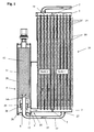
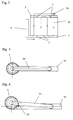
- FIGS. 1-4 show an exemplary embodiment with an external transfer line and with a filter located below the container.
- FIGS. 5-8 show an exemplary embodiment with a transfer line integrated in the collecting tube and with a filter present in the container.
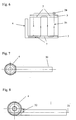
- Fig. 9 shows a flared manifold with integrated transfer line.
- stages 1 and 2 each consist of a plurality of flat heat exchanger tubes 15 , wherein between the heat exchanger tubes 15 corrugated fins 18 are arranged, which are flowed through by the cooling air to cool the refrigerant in the heat exchanger tubes 15 and to condense.
- the refrigerant leaves the condenser 30 in the fully liquefied and supercooled state.
- the sections of the condenser 30 shown in FIGS. 1 and 5 are therefore in the stage 1 by several stages, which are connected upstream, as can be seen in principle from FIGS. 2 and 6.
- the steps 1, 2 are formed by the appropriate arrangement of partitions 7 in the headers 3 and 5 .
- the refrigerant 25 enters the condenser 30 through the inlet and outlet flange 26 . It flows through several stages 1 before it enters the transfer line 10 through the inlet opening 27 . Through the transfer line 10 , the entire refrigerant 25 is guided past the stage 2 and transferred to the collector 4 .
- the transfer line 10 enters the collector 4 and passes through the space 28 , the filter 29 and above the filter 29, the liquid mixed with small amounts of gas refrigerant 25 via the inflow opening 14 into the interior of the collector 4 from.
- the desiccant is in a container 12th
- the refrigerant flows through the filter 29 to separate the smallest particles and into the return flow 28th
- the dividers 36 are to guarantee that the entire refrigerant 25 flows through the filter 29 .
- the refrigerant 25 leaves the collector 4 and flows through the front end 35 of the collecting tube 3 into the stage 2 of the condenser 30 .
- the subcooling in stage 2 After the subcooling in stage 2 , it passes via the collecting pipe 5 and the outlet 19 to the inlet and outlet flange 26, in order then to continue its travel in the air conditioning circuit (not shown). 4, an alternative to the first embodiment is shown. In some cases it may be necessary to place the collector 4 slightly in front of or behind the plane 33 of the tube-fin block of the condenser 30 . The collector 4 is then offset by the distance 32 from the plane 33 to the front or rear, but otherwise identical to the first embodiment.
- the refrigerant 25 enters the condenser 30 through the inlet and outlet flange 26 . It flows through several stages 1 before it enters the transfer line 10 through the inlet opening 27 . Through the transfer line 10 , the entire refrigerant 25 is passed to the stage 2 over and transferred to the collector 4 . At the flange 8 , the transfer line 10 enters the collector 4 a. The flange 8 is also the inflow opening 14 , through which the refrigerant 25 flows into an inner shell 20 . In the inner jacket 20 , the desiccant is in a container 12th On his way It happens to the above the dryer arranged filter 29 to separate the smallest particles.
- FIG. 8 also shows an alternative to the second exemplary embodiment. In some cases it may be necessary to place the collector 4 slightly in front of or behind the plane 33 of the tube - fin block of the condenser 1 . The collector 4 is then offset by the distance 32 from the plane 33 to the front or rear, but otherwise identical to the second embodiment.
- FIG. 9 an alternative embodiment of a transfer line is shown.
- the manifold 3 was enlarged on the collector 4 side facing 35 in diameter.
- the manifold 3 has been widened to accommodate the transfer line 10 so that the returning refrigerant 25 undergoes no unnecessary pressure loss through a too narrow manifold 3 .
- the installation of the transfer line 10 is easier to accomplish.
Landscapes
- Engineering & Computer Science (AREA)
- Physics & Mathematics (AREA)
- Mechanical Engineering (AREA)
- Thermal Sciences (AREA)
- General Engineering & Computer Science (AREA)
- Air-Conditioning For Vehicles (AREA)
- Heat-Exchange Devices With Radiators And Conduit Assemblies (AREA)
- Valve Device For Special Equipments (AREA)
- Oscillators With Electromechanical Resonators (AREA)
- Inverter Devices (AREA)
Abstract
Description
- Die Erfindung betrifft einen Kondensator für die Klimaanlage eines Kraftfahrzeugs, dessen Rohre in mehreren Stufen von dem Kältemittel durchströmbar sind, wozu er zwei Sammelrohre aufweist, und einen, mit einem der Sammelrohre über Ein - und Ausströmöffnungen zwischen den Stufen in Strömungsverbindung stehenden, Sammler besitzt, der einen Außenmantel aufweist.
Ein solcher Kondensator mit vertikal verlaufenden Wärmetauscherrohren ist aus der Fig. 7 desEP 769 666 A1 - Im
EP 974 793 A2
In beiden Fällen ist der Sammler lösbar, über einen angelöteten Verbindungsblock, mit einem der Sammelrohre verbunden. Es scheint keine erfinderische Tätigkeit erforderlich zu sein, um die lösbare Verbindung in eine unlösbar, beispielsweise in eine Lötverbindung, umzugestalten.
Ein weiterer dem Oberbegriff entsprechender Kondensator mit Sammler ist aus demJP 2001-174103
Der Erfinder hat sich die Aufgabe gestellt, seinen Kondensator mit Sammler so auszubilden, dass die Trennfunktion und/oder Trocknungsfunktion des Sammlers verbessert wird. - Erfindungsgemäß wurde diese Aufgabe bei einem Kondensator gemäß Oberbegriff des Anspruchs 1 mit den Merkmalen aus dessen Kennzeichen gelöst.
Es ist vorgesehen, dass der Sammler einen Innenmantel aufweist, wobei Innenmantel und Außenmantel koaxial zueinander angeordnet sind, so dass zwischen dem Innenmantel und dem Außenmantel ein Strömungskanal für das Kältemittel ausgebildet ist, wobei die eine Ein - oder Ausströmöffnung mit dem vom Innenmantel umschlossenen Raum kommuniziert und die andere Ein - oder Ausströmöffnung im Außenmantel angeordnet ist.
In dem Raum, der von dem Innenmantel umschlossen ist, befindet sich ein Trockner und gemäß einer Ausführung auch ein Filter.
Es kann auch vorgesehen werden, dass der Filter oberhalb des Trockners angeordnet ist, wobei das gereinigte Kältemittel nach Durchströmung des Filters seine Strömungsrichtung umkehrt und über den Strömungskanal und die andere Ein - oder Ausströmöffnung in die genannte Stufe des Kondensators eintritt.
Es kann demgegenüber vorgesehen werden, dass sich in dem Raum, der von dem Innenmantel umschlossen ist, nur der Trockner befindet und dass der Filter im Strömungsweg vor der Ausströmöffnung angeordnet ist.
Es ist eine Überführungsleitung von einer Stufe zu der einen Ein - oder Ausströmöffnung des Sammlers vorgesehen. Die Überführungsleitung erstreckt sich etwa über den Bereich der benachbarten Stufe. Die andere Ein - oder Ausströmöffnung des Sammlers ist etwa am stirnseitigen Ende des Sammelrohres vorgesehen. Dadurch wurde eine besonders kompakte Anordnung geschaffen, die sich hervorragend zu einer einzigen Lötkonstruktion verbinden lässt. Jede Stufe besteht aus mehreren parallelen Wärmetauscherrohren des Kondensators. Ferner wird durch das Vorsehen der Überführungsleitung die Position des Sammlers verbessert. In der Fig. 7 desEP 769 666 A1
Die Überführungsleitung kann entweder innerhalb des Sammelrohrs oder außerhalb des Sammelrohrs angeordnet sein. Die Kompaktheit wird weiter verbessert, wenn eine innerhalb des Sammelrohres angeordnete Überführungsleitung gewählt wird. Hier kann es sich um ein etwa koaxiales Rohr handeln. Das Sammelrohr könnte im Bereich der Überführungsleitung aber auch lediglich durch eine Wand unterteilt sein.
Die andere Ein - oder Ausströmöffnung ist vorzugsweise unmittelbar zwischen dem Mantel des Sammlers und dem stirnseitigen Ende des Sammelrohres vorgesehen. Dadurch befindet sich der Sammler in unmittelbarer Nähe des Rohr - Rippen - Blocks und insbesondere in unmittelbarer Nähe und parallel zu einem der Seitenteile, die den Rohr - Rippen - Block gewöhnlich an den Seiten verstärken. An diesen Seitenteilen kann im Bedarfsfall eine zusätzliche Halterung des Sammlers vorgesehen werden.
Der erfindungsgemäße Kondensator ist besonders zur Kombination mit einem Wasserkühler und/oder anderen Wärmetauschern des Kraftfahrzeuges geeignet, die ebenfalls oben und unten horizontal angeordnete Sammelkästen und vertikale Wärmetauscherrohre aufweisen.
Nachfolgend wird die Erfindung in zwei bevorzugten Ausführungsbeispielen an Hand der beiliegenden Abbildungen beschrieben. Aus dieser Beschreibung gehen weitere Merkmale und Vorteile der Erfindung hervor, die sich als besonders wesentlich herausstellen können.
Die Fig. 1 - 4 zeigen ein Ausführungsbeispiel mit einer außen liegenden Überführungsleitung und mit einem unterhalb des Behälters liegendem Filter. Die Fig. 5 - 8 zeigen ein Ausführungsbeispiel mit einer im Sammelrohr integrierten Überführungsleitung und mit im Behälter vorhandenem Filter. Die Fig. 9 zeigt ein aufgeweitetes Sammelrohr mit integrierter Überführungsleitung.
Die in den Ausführungsbeispielen angedeuteten Stufen 1 und 2 bestehen jeweils aus mehreren flachen Wärmetauscherrohren 15, wobei zwischen den Wärmetauscherrohren 15 Wellrippen 18 angeordnet sind, die von der Kühlluft durchströmt werden, um das Kältemittel in den Wärmetauscherrohren 15 zu kühlen bzw. zu kondensieren. Das Kältemittel verlässt im vollständig verflüssigten und unterkühlten Zustand den Kondensator 30. - Bei dem in den Fig. 1 und 5 dargestellten Ausschnitten aus dem Kondensator 30 handelt es sich deshalb bei der Stufe 1 um mehrere Stufen, die vorgeschaltet sind, wie es prinzipiell aus den Fig. 2 und 6 erkennbar ist. Die Stufen 1, 2 entstehen durch die zweckmäßige Anordnung von Trennwänden 7 in den Sammelrohren 3 und 5.
In den Fig. 1 und 2 tritt das Kältemittel 25 durch den Eintritts - und Austrittsflansch 26 in den Kondensator 30 ein. Es fließt durch mehrere Stufen 1 bevor es durch die Einlassöffnung 27 in die Überführungsleitung 10 eintritt. Durch die Überführungsleitung 10 wird das gesamte Kältemittel 25 an der Stufe 2 vorbeigeleitet und in den Sammler 4 überführt. Am Flansch 8 tritt die Überführungsleitung 10 in den Sammler 4 ein und durchquert den Raum 28, den Filter 29 und gibt oberhalb des Filters 29 das flüssige mit geringen Gasanteilen vermischte Kältemittel 25 über die Einströmöffnung 14 in das Innere des Sammlers 4 ab. Im Sammler 4 befindet sich das Trocknungsmittel in einem Behälter 12. Auf seinem weiteren Weg strömt das Kältemittel durch den Filter 29, um kleinste Partikel abzuscheiden und in den Rückströmraum 28. Die Trennstege 36 sollen garantieren, dass das gesamte Kältemittel 25 durch den Filter 29 strömt. Über die Ausströmöffnung 13 am Flansch 9 verlässt das Kältemittel 25 den Sammler 4 und strömt durch das stirnseitige Ende 35 des Sammelrohres 3 in die Stufe 2 des Kondensators 30. Nach der Unterkühlung in der Stufe 2 gelangt es über das Sammelrohr 5 und den Auslass 19 zum Ein - und Austrittsflansch 26 um dann seinen Weg im nicht gezeigten Klimatisierungskreislauf fortzusetzen. In Fig. 4 ist eine Alternative zum ersten Ausführungsbeispiel gezeigt. In einigen Fällen kann es notwendig sein den Sammler 4 etwas vor oder hinter der Ebene 33 des Rohr - Rippen - Blocks des Kondensators 30 anzuordnen. Der Sammler 4 ist dann um den Abstand 32 aus der Ebene 33 nach vorn oder hinten versetzt, aber ansonsten identisch zum ersten Ausführungsbeispiel. - In Fig. 5 und 6 tritt das Kältemittel 25 durch den Eintritts- und Austrittsflansch 26 in den Kondensator 30 ein. Es fließt durch mehrere Stufen 1 bevor es durch die Einlassöffnung 27 in die Überführungsleitung 10 eintritt. Durch die Überführungsleitung 10 wird das gesamte Kältemittel 25 an der Stufe 2 vorbei geleitet und in den Sammler 4 überführt. Am Flansch 8 tritt die Überführungsleitung 10 in den Sammler 4 ein. Am Flansch 8 befindet sich auch die Einströmöffnung 14, durch den das Kältemittel 25 in einen Innenmantel 20 einströmt. Im Innenmantel 20 befindet sich das Trocknungsmittel in einem Behälter 12. Auf seinem weiteren Weg passiert es den oberhalb des Trockners angeordneten Filter 29 um kleinste Partikel abzuscheiden. Zwischen dem Außenmantel 31 des Sammlers 4 und dem Innenmantel 20 befindet sich der Strömungskanal 16, durch den das Kältemittel 25 nach unten fließen kann. Über die Ausströmsöffnung 13 am Flansch 9 verlässt das Kältemittel 25 den Sammler 4 und strömt durch das stirnseitige Ende 35 des Sammelrohres 3 in die Stufe 2 des Kondensators 30. Nach der Unterkühlung in der Stufe 2 gelangt es über das Sammelrohr 5 und den Auslass 19 zum Ein - und Austrittsflansch 26. In Fig. 8 ist noch eine Alternative zum zweiten Ausführungsbeispiel gezeigt. In einigen Fällen kann es notwendig sein, den Sammler 4 etwas vor oder hinter der Ebene 33 des Rohr - Rippen - Blocks des Kondensators 1 anzuordnen. Der Sammler 4 ist dann um den Abstand 32 aus der Ebene 33 nach vorn oder hinten versetzt, aber ansonsten identisch mit dem zweiten Ausführungsbeispiel.
- In Fig. 9 ist noch eine alternative Ausbildung einer Überführungsleitung gezeigt. Hier ist lediglich ein Ausschnitt des Sammelrohres 3 zu sehen. In diesem Fall wurde das Sammelrohr 3 auf der dem Sammler 4 zugewandten Seite 35 im Durchmesser vergrößert. Vor der letzten Trennwand 7 im Sammelrohr 3 ist das Sammelrohr 3 aufgeweitet worden, um die Überführungsleitung 10 aufzunehmen, damit das zurückfließende Kältemittel 25 keinen unnötigen Druckverlust durch ein zu enges Sammelrohr 3 erfährt. Außerdem ist der Einbau der Überführungsleitung 10 leichter zu bewerkstelligen.
Claims (13)
- Kondensator (30) für die Klimaanlage eines Kraftfahrzeugs, dessen Wärmetauscherrohre (15) in mehreren Stufen (1, 2) von einem Kältemittel (25) durchströmbar sind, wozu er zwei Sammelrohre (3, 5) aufweist, die mittels Trennwänden (7) derart unterteilt sind, dass die aus mehreren Wärmetauscherrohren (15) bestehenden Stufen (1, 2) entstehen, und der einen mit einem der Sammelrohre (3) über Ein - und Ausströmöffnungen (13, 14) zwischen den Stufen (1, 2) in Strömungsverbindung stehenden Sammler (4) besitzt, der einen Außenmantel (31) aufweist,
dadurch gekennzeichnet, dass
der Sammler (4) einen Innenmantel (20) aufweist, wobei Innenmantel (20) und Außenmantel (31) koaxial zueinander angeordnet sind, so dass zwischen dem Innenmantel (20) und dem Außenmantel (31) ein Strömungskanal (16) für das Kältemittel (25) ausgebildet ist, wobei die eine Ein - oder Ausströmöffnung (14) mit dem vom Innenmantel (20) umschlossenen Raum kommuniziert und die andere Ein - oder Ausströmöffnung (13) im Außenmantel (31) angeordnet ist. - Kondensator nach Anspruch 1, dadurch gekennzeichnet, dass sich in dem Raum, der von dem Innenmantel (20) umschlossen ist, ein Trockner (12) und ein Filter (29) befinden.
- Kondensator nach Anspruch 1 oder 2, dadurch gekennzeichnet, dass der Filter (29) oberhalb des Trockners (12) angeordnet ist, wobei das gereinigte Kältemittel (25) nach Durchströmung des Filters (29) seine Strömungsrichtung umkehrt und über den Strömungskanal (16) und die andere Ein - oder Ausströmöffnung (14) in die genannte Stufe (2) des Kondensators eintritt.
- Kondensator nach Anspruch 1, dadurch gekennzeichnet, dass sich in dem Raum, der von dem Innenmantel (20) umschlossen ist, ein Trockner (12) befindet und ein Filter (29) im Strömungsweg vor der Ausströmöffnung (14) angeordnet ist.
- Kondensator nach einem der vorstehenden Ansprüche, dadurch gekennzeichnet, dass eine Überführungsleitung (10) von einer Stufe (1) zu der einen Ein - oder Ausströmöffnung (14) des Sammlers (4) vorgesehen ist, die sich in Querrichtung der Rohre (15) etwa über eine benachbarte Stufe (2) erstreckt, und dass die andere Ein - oder Ausströmöffnung (13) des Sammlers (4) etwa am stirnseitigen Ende (35) des Sammelrohrs (3) oder in dessen Nähe vorgesehen ist, um das Kältemittel in die benachbarte Stufe (2) zu leiten.
- Kondensator nach Anspruch 5, dadurch gekennzeichnet, dass die Überführungsleitung (10) innerhalb des Sammelrohrs (3) angeordnet ist.
- Kondensator nach Anspruch 5, dadurch gekennzeichnet, dass die Überführungsleitung (10) außerhalb des Sammelrohrs (3) angeordnet ist und vorzugsweise parallel dazu verläuft.
- Kondensator nach den Ansprüchen 5 und 6, dadurch gekennzeichnet, dass die Überführungsleitung (10) an einem Ende in einer Öffnung in der Trennwand (7) steckt und die Einlaßöffnung (27) bildet und am anderen Ende in den Sammler (4) eintritt.
- Kondensator nach den Ansprüchen 5 und 7, dadurch gekennzeichnet, dass die Überführungsleitung (10) an einem Ende in der Nähe der Trennwand (7) im Sammelrohr (3) steckt und die Einlaßöffnung (27) bildet und am anderen Ende in dem Sammler (4) steckt.
- Kondensator nach Anspruch 5, dadurch gekennzeichnet, dass das Sammelrohr (3) über die Länge der Überführungsleitung (10) einen größeren Durchmesser aufweist als im übrigen Längenbereich, um den Einbau der Überführungsleitung (10) zu erleichtern.
- Kondensator nach einem der vorstehenden Ansprüche, dadurch gekennzeichnet, dass die Sammelrohre (3, 5) des Kondensators (30) horizontal verlaufen, so dass die Wärmetauscherrohre (15) des Kondensators (30) und der parallel dazu vorgesehene Sammler (4) vertikal angeordnet sind.
- Kondensator nach einem der vorstehenden Ansprüche, dadurch gekennzeichnet, dass beide Ein - oder Ausströmöffnungen (13, 14) seitlich im Innen - (20) bzw. Außenmantel (31) des Sammlers (4) angeordnet sind.
- Kondensator nach einem der vorstehenden Ansprüche, dadurch gekennzeichnet, dass der eine Flansch (8) im Boden des Sammlers und der andere Flansch in dessen Nähe im Außenmantel (31) des Sammlers (4) angeordnet ist.
Applications Claiming Priority (2)
| Application Number | Priority Date | Filing Date | Title |
|---|---|---|---|
| DE10357176A DE10357176A1 (de) | 2003-12-06 | 2003-12-06 | Kondensator |
| EP04027603A EP1538407B1 (de) | 2003-12-06 | 2004-11-20 | Kondensator |
Related Parent Applications (2)
| Application Number | Title | Priority Date | Filing Date |
|---|---|---|---|
| EP04027603.2 Division | 2004-11-20 | ||
| EP04027603A Division EP1538407B1 (de) | 2003-12-06 | 2004-11-20 | Kondensator |
Publications (3)
| Publication Number | Publication Date |
|---|---|
| EP1741998A2 true EP1741998A2 (de) | 2007-01-10 |
| EP1741998A3 EP1741998A3 (de) | 2007-08-22 |
| EP1741998B1 EP1741998B1 (de) | 2010-04-14 |
Family
ID=34442492
Family Applications (2)
| Application Number | Title | Priority Date | Filing Date |
|---|---|---|---|
| EP06021990A Expired - Lifetime EP1741998B1 (de) | 2003-12-06 | 2004-11-20 | Kondensator |
| EP04027603A Expired - Lifetime EP1538407B1 (de) | 2003-12-06 | 2004-11-20 | Kondensator |
Family Applications After (1)
| Application Number | Title | Priority Date | Filing Date |
|---|---|---|---|
| EP04027603A Expired - Lifetime EP1538407B1 (de) | 2003-12-06 | 2004-11-20 | Kondensator |
Country Status (4)
| Country | Link |
|---|---|
| US (1) | US6971251B2 (de) |
| EP (2) | EP1741998B1 (de) |
| AT (2) | ATE464518T1 (de) |
| DE (3) | DE10357176A1 (de) |
Families Citing this family (4)
| Publication number | Priority date | Publication date | Assignee | Title |
|---|---|---|---|---|
| FR2965336B1 (fr) | 2010-09-28 | 2012-09-14 | Valeo Systemes Thermiques | Ensemble d'un echangeur de chaleur biphasique et d'une bouteille |
| JP6216113B2 (ja) * | 2012-04-02 | 2017-10-18 | サンデンホールディングス株式会社 | 熱交換器及びそれを用いたヒートポンプシステム |
| JP6541219B2 (ja) * | 2015-05-19 | 2019-07-10 | サンデン・オートモーティブクライメイトシステム株式会社 | 受液器付き熱交換器 |
| EP3855095B1 (de) * | 2020-01-22 | 2023-08-23 | Valeo Autosystemy SP. Z.O.O. | Wärmetauscher mit horizontal positioniertem sammler-trockner |
Citations (4)
| Publication number | Priority date | Publication date | Assignee | Title |
|---|---|---|---|---|
| EP0769666A1 (de) | 1995-10-18 | 1997-04-23 | Calsonic Corporation | Verflüssiger mit Flüssigkeitsbehälter |
| US5937671A (en) | 1996-11-08 | 1999-08-17 | Zexel Corporation | Liquid tank |
| EP0974793A2 (de) | 1998-07-23 | 2000-01-26 | Sanden Corporation | Mit Sammler ausgerüsteter Verflüssiger |
| JP2001174103A (ja) | 1999-12-14 | 2001-06-29 | Denso Corp | 冷媒凝縮器 |
Family Cites Families (12)
| Publication number | Priority date | Publication date | Assignee | Title |
|---|---|---|---|---|
| JP2827404B2 (ja) * | 1989-04-28 | 1998-11-25 | 株式会社デンソー | 冷媒凝縮器 |
| JP3116996B2 (ja) * | 1996-10-30 | 2000-12-11 | 株式会社デンソー | 受液器一体型冷媒凝縮器 |
| US6304222B1 (en) * | 1997-12-22 | 2001-10-16 | Nortel Networks Limited | Radio communications handset antenna arrangements |
| JP4052706B2 (ja) * | 1998-01-22 | 2008-02-27 | 昭和電工株式会社 | サブクールシステムコンデンサ |
| JPH11270927A (ja) * | 1998-03-20 | 1999-10-05 | Zexel:Kk | 熱交換器の接続構造及び接続部材 |
| DE19926990B4 (de) * | 1998-06-16 | 2009-02-05 | Denso Corp., Kariya-shi | Mit integriertem Aufnahmebehälter ausgestatteter Kondensator für einen Kühl- bzw. Kältemittelzyklus |
| IT1304676B1 (it) * | 1998-10-06 | 2001-03-28 | Magneti Marelli Climat Srl | Condensatore per impianti di condizionamento d'aria di veicoli, aventeun accumulatore integrato ed una sezione di sottoraffreddamento. |
| EP1202007A1 (de) * | 2000-10-25 | 2002-05-02 | Skg Italiana Spa | Verflüssiger und Trockner |
| JP2002187424A (ja) * | 2000-12-19 | 2002-07-02 | Denso Corp | 車両用凝縮器 |
| DE10213176A1 (de) * | 2002-03-23 | 2003-10-02 | Behr Gmbh & Co | Kältmittelkondensator |
| DE20208337U1 (de) * | 2002-05-28 | 2003-10-16 | Thermo King Deutschland GmbH, 68766 Hockenheim | Anordnung zum Klimatisieren eines Fahrzeugs |
| ITTO20030768A1 (it) * | 2003-10-02 | 2005-04-03 | Denso Thermal Systems Spa | Condensatore per veicoli e corpo integrato radiatore- |
-
2003
- 2003-12-06 DE DE10357176A patent/DE10357176A1/de not_active Withdrawn
-
2004
- 2004-11-20 AT AT06021990T patent/ATE464518T1/de not_active IP Right Cessation
- 2004-11-20 EP EP06021990A patent/EP1741998B1/de not_active Expired - Lifetime
- 2004-11-20 DE DE502004011057T patent/DE502004011057D1/de not_active Expired - Lifetime
- 2004-11-20 DE DE502004003826T patent/DE502004003826D1/de not_active Expired - Lifetime
- 2004-11-20 EP EP04027603A patent/EP1538407B1/de not_active Expired - Lifetime
- 2004-11-20 AT AT04027603T patent/ATE362601T1/de not_active IP Right Cessation
- 2004-12-06 US US11/006,172 patent/US6971251B2/en not_active Expired - Fee Related
Patent Citations (4)
| Publication number | Priority date | Publication date | Assignee | Title |
|---|---|---|---|---|
| EP0769666A1 (de) | 1995-10-18 | 1997-04-23 | Calsonic Corporation | Verflüssiger mit Flüssigkeitsbehälter |
| US5937671A (en) | 1996-11-08 | 1999-08-17 | Zexel Corporation | Liquid tank |
| EP0974793A2 (de) | 1998-07-23 | 2000-01-26 | Sanden Corporation | Mit Sammler ausgerüsteter Verflüssiger |
| JP2001174103A (ja) | 1999-12-14 | 2001-06-29 | Denso Corp | 冷媒凝縮器 |
Also Published As
| Publication number | Publication date |
|---|---|
| DE502004003826D1 (de) | 2007-06-28 |
| EP1538407B1 (de) | 2007-05-16 |
| EP1741998B1 (de) | 2010-04-14 |
| DE502004011057D1 (de) | 2010-05-27 |
| EP1538407A3 (de) | 2005-10-05 |
| DE10357176A1 (de) | 2005-06-30 |
| ATE362601T1 (de) | 2007-06-15 |
| ATE464518T1 (de) | 2010-04-15 |
| US20050120739A1 (en) | 2005-06-09 |
| US6971251B2 (en) | 2005-12-06 |
| EP1741998A3 (de) | 2007-08-22 |
| EP1538407A2 (de) | 2005-06-08 |
Similar Documents
| Publication | Publication Date | Title |
|---|---|---|
| DE4245046C5 (de) | Kondensator für eine Klimaanlage eines Fahrzeuges | |
| DE10162200A1 (de) | Mit einem Aufnahmebehälter zusammengefasster Kondensator für ein Fahrzeug | |
| DE112009001070T5 (de) | Kondensator | |
| DE10123347B4 (de) | Wärmeaustauscher mit Phasen-Änderung von Kältemittel | |
| DE112019003711T5 (de) | Integrierter Flüssigkeits-/Luftgekühlter Kondensator und Niedertemperatur-Kühler | |
| DE102011113453A1 (de) | Kühler | |
| WO2005038381A1 (de) | Kühlmittelkühler eines kraftfahrzeuges | |
| DE102017211736A1 (de) | Kondensator | |
| DE4330214B4 (de) | Wärmetauscher | |
| EP2606292B1 (de) | Kältemittelkondensatorbaugruppe | |
| DE60017969T2 (de) | Kondensator | |
| EP1741998B1 (de) | Kondensator | |
| DE102007010530B4 (de) | Behälter für einen Wärmetauscher und Wärmetauscher | |
| DE102004047304A1 (de) | Unterkühlender Kondensator | |
| DE102021213376A1 (de) | Wärmeübertrager und Kältemittelkreislauf mit einem Wärmeübertrager | |
| DE4213509A1 (de) | Wärmetauscher, insbesondere Kondensator für Fahrzeug-Klimaanlagen | |
| DE20009332U1 (de) | Klimagerät für Personentransportfahrzeuge | |
| EP2108912B1 (de) | Kondensator, insbesondere für eine Kraftfahrzeug-Klimaanlage | |
| EP1310760B1 (de) | Kältemittelkondensator | |
| DE19957307A1 (de) | Zweikreis-Wärmeübertrager | |
| EP1684032B1 (de) | Kondensator für eine Klimaanlage, insbesondere eines Kraftfahrzeuges | |
| DE102004028028A1 (de) | Wärmetauscher | |
| DE102011089091A1 (de) | Wärmeübertrager | |
| DE2831022A1 (de) | Waermetauscheranordnung | |
| DE10025325B4 (de) | Akkumulator für ein Klimaanlagensystem |
Legal Events
| Date | Code | Title | Description |
|---|---|---|---|
| PUAI | Public reference made under article 153(3) epc to a published international application that has entered the european phase |
Free format text: ORIGINAL CODE: 0009012 |
|
| AC | Divisional application: reference to earlier application |
Ref document number: 1538407 Country of ref document: EP Kind code of ref document: P |
|
| AK | Designated contracting states |
Kind code of ref document: A2 Designated state(s): AT BE BG CH CY CZ DE DK EE ES FI FR GB GR HU IE IS IT LI LU MC NL PL PT RO SE SI SK TR |
|
| PUAL | Search report despatched |
Free format text: ORIGINAL CODE: 0009013 |
|
| AK | Designated contracting states |
Kind code of ref document: A3 Designated state(s): AT BE BG CH CY CZ DE DK EE ES FI FR GB GR HU IE IS IT LI LU MC NL PL PT RO SE SI SK TR |
|
| 17P | Request for examination filed |
Effective date: 20080222 |
|
| AKX | Designation fees paid |
Designated state(s): AT BE BG CH CY CZ DE DK EE ES FI FR GB GR HU IE IS IT LI LU MC NL PL PT RO SE SI SK TR |
|
| GRAP | Despatch of communication of intention to grant a patent |
Free format text: ORIGINAL CODE: EPIDOSNIGR1 |
|
| GRAS | Grant fee paid |
Free format text: ORIGINAL CODE: EPIDOSNIGR3 |
|
| GRAA | (expected) grant |
Free format text: ORIGINAL CODE: 0009210 |
|
| AC | Divisional application: reference to earlier application |
Ref document number: 1538407 Country of ref document: EP Kind code of ref document: P |
|
| AK | Designated contracting states |
Kind code of ref document: B1 Designated state(s): AT BE BG CH CY CZ DE DK EE ES FI FR GB GR HU IE IS IT LI LU MC NL PL PT RO SE SI SK TR |
|
| REG | Reference to a national code |
Ref country code: GB Ref legal event code: FG4D Free format text: NOT ENGLISH |
|
| REG | Reference to a national code |
Ref country code: CH Ref legal event code: EP |
|
| REG | Reference to a national code |
Ref country code: IE Ref legal event code: FG4D Free format text: LANGUAGE OF EP DOCUMENT: GERMAN |
|
| REF | Corresponds to: |
Ref document number: 502004011057 Country of ref document: DE Date of ref document: 20100527 Kind code of ref document: P |
|
| REG | Reference to a national code |
Ref country code: NL Ref legal event code: VDEP Effective date: 20100414 |
|
| PG25 | Lapsed in a contracting state [announced via postgrant information from national office to epo] |
Ref country code: NL Free format text: LAPSE BECAUSE OF FAILURE TO SUBMIT A TRANSLATION OF THE DESCRIPTION OR TO PAY THE FEE WITHIN THE PRESCRIBED TIME-LIMIT Effective date: 20100414 Ref country code: ES Free format text: LAPSE BECAUSE OF FAILURE TO SUBMIT A TRANSLATION OF THE DESCRIPTION OR TO PAY THE FEE WITHIN THE PRESCRIBED TIME-LIMIT Effective date: 20100725 Ref country code: SE Free format text: LAPSE BECAUSE OF FAILURE TO SUBMIT A TRANSLATION OF THE DESCRIPTION OR TO PAY THE FEE WITHIN THE PRESCRIBED TIME-LIMIT Effective date: 20100414 |
|
| REG | Reference to a national code |
Ref country code: IE Ref legal event code: FD4D |
|
| PG25 | Lapsed in a contracting state [announced via postgrant information from national office to epo] |
Ref country code: IS Free format text: LAPSE BECAUSE OF FAILURE TO SUBMIT A TRANSLATION OF THE DESCRIPTION OR TO PAY THE FEE WITHIN THE PRESCRIBED TIME-LIMIT Effective date: 20100814 Ref country code: SI Free format text: LAPSE BECAUSE OF FAILURE TO SUBMIT A TRANSLATION OF THE DESCRIPTION OR TO PAY THE FEE WITHIN THE PRESCRIBED TIME-LIMIT Effective date: 20100414 Ref country code: FI Free format text: LAPSE BECAUSE OF FAILURE TO SUBMIT A TRANSLATION OF THE DESCRIPTION OR TO PAY THE FEE WITHIN THE PRESCRIBED TIME-LIMIT Effective date: 20100414 |
|
| PG25 | Lapsed in a contracting state [announced via postgrant information from national office to epo] |
Ref country code: CY Free format text: LAPSE BECAUSE OF FAILURE TO SUBMIT A TRANSLATION OF THE DESCRIPTION OR TO PAY THE FEE WITHIN THE PRESCRIBED TIME-LIMIT Effective date: 20100505 Ref country code: GR Free format text: LAPSE BECAUSE OF FAILURE TO SUBMIT A TRANSLATION OF THE DESCRIPTION OR TO PAY THE FEE WITHIN THE PRESCRIBED TIME-LIMIT Effective date: 20100715 Ref country code: PL Free format text: LAPSE BECAUSE OF FAILURE TO SUBMIT A TRANSLATION OF THE DESCRIPTION OR TO PAY THE FEE WITHIN THE PRESCRIBED TIME-LIMIT Effective date: 20100414 |
|
| PG25 | Lapsed in a contracting state [announced via postgrant information from national office to epo] |
Ref country code: EE Free format text: LAPSE BECAUSE OF FAILURE TO SUBMIT A TRANSLATION OF THE DESCRIPTION OR TO PAY THE FEE WITHIN THE PRESCRIBED TIME-LIMIT Effective date: 20100414 Ref country code: DK Free format text: LAPSE BECAUSE OF FAILURE TO SUBMIT A TRANSLATION OF THE DESCRIPTION OR TO PAY THE FEE WITHIN THE PRESCRIBED TIME-LIMIT Effective date: 20100414 Ref country code: PT Free format text: LAPSE BECAUSE OF FAILURE TO SUBMIT A TRANSLATION OF THE DESCRIPTION OR TO PAY THE FEE WITHIN THE PRESCRIBED TIME-LIMIT Effective date: 20100816 Ref country code: IE Free format text: LAPSE BECAUSE OF FAILURE TO SUBMIT A TRANSLATION OF THE DESCRIPTION OR TO PAY THE FEE WITHIN THE PRESCRIBED TIME-LIMIT Effective date: 20100414 |
|
| PLBE | No opposition filed within time limit |
Free format text: ORIGINAL CODE: 0009261 |
|
| STAA | Information on the status of an ep patent application or granted ep patent |
Free format text: STATUS: NO OPPOSITION FILED WITHIN TIME LIMIT |
|
| PG25 | Lapsed in a contracting state [announced via postgrant information from national office to epo] |
Ref country code: SK Free format text: LAPSE BECAUSE OF FAILURE TO SUBMIT A TRANSLATION OF THE DESCRIPTION OR TO PAY THE FEE WITHIN THE PRESCRIBED TIME-LIMIT Effective date: 20100414 Ref country code: RO Free format text: LAPSE BECAUSE OF FAILURE TO SUBMIT A TRANSLATION OF THE DESCRIPTION OR TO PAY THE FEE WITHIN THE PRESCRIBED TIME-LIMIT Effective date: 20100414 Ref country code: CZ Free format text: LAPSE BECAUSE OF FAILURE TO SUBMIT A TRANSLATION OF THE DESCRIPTION OR TO PAY THE FEE WITHIN THE PRESCRIBED TIME-LIMIT Effective date: 20100414 |
|
| 26N | No opposition filed |
Effective date: 20110117 |
|
| PG25 | Lapsed in a contracting state [announced via postgrant information from national office to epo] |
Ref country code: IT Free format text: LAPSE BECAUSE OF FAILURE TO SUBMIT A TRANSLATION OF THE DESCRIPTION OR TO PAY THE FEE WITHIN THE PRESCRIBED TIME-LIMIT Effective date: 20100414 |
|
| BERE | Be: lapsed |
Owner name: MODINE MANUFACTURING CY Effective date: 20101130 |
|
| PG25 | Lapsed in a contracting state [announced via postgrant information from national office to epo] |
Ref country code: MC Free format text: LAPSE BECAUSE OF NON-PAYMENT OF DUE FEES Effective date: 20101130 |
|
| REG | Reference to a national code |
Ref country code: CH Ref legal event code: PL |
|
| PG25 | Lapsed in a contracting state [announced via postgrant information from national office to epo] |
Ref country code: CH Free format text: LAPSE BECAUSE OF NON-PAYMENT OF DUE FEES Effective date: 20101130 Ref country code: LI Free format text: LAPSE BECAUSE OF NON-PAYMENT OF DUE FEES Effective date: 20101130 |
|
| PG25 | Lapsed in a contracting state [announced via postgrant information from national office to epo] |
Ref country code: BE Free format text: LAPSE BECAUSE OF NON-PAYMENT OF DUE FEES Effective date: 20101130 |
|
| REG | Reference to a national code |
Ref country code: AT Ref legal event code: MM01 Ref document number: 464518 Country of ref document: AT Kind code of ref document: T Effective date: 20101120 |
|
| PG25 | Lapsed in a contracting state [announced via postgrant information from national office to epo] |
Ref country code: AT Free format text: LAPSE BECAUSE OF NON-PAYMENT OF DUE FEES Effective date: 20101120 |
|
| PG25 | Lapsed in a contracting state [announced via postgrant information from national office to epo] |
Ref country code: BG Free format text: LAPSE BECAUSE OF FAILURE TO SUBMIT A TRANSLATION OF THE DESCRIPTION OR TO PAY THE FEE WITHIN THE PRESCRIBED TIME-LIMIT Effective date: 20100414 Ref country code: LU Free format text: LAPSE BECAUSE OF NON-PAYMENT OF DUE FEES Effective date: 20101120 Ref country code: HU Free format text: LAPSE BECAUSE OF FAILURE TO SUBMIT A TRANSLATION OF THE DESCRIPTION OR TO PAY THE FEE WITHIN THE PRESCRIBED TIME-LIMIT Effective date: 20101015 |
|
| PG25 | Lapsed in a contracting state [announced via postgrant information from national office to epo] |
Ref country code: TR Free format text: LAPSE BECAUSE OF FAILURE TO SUBMIT A TRANSLATION OF THE DESCRIPTION OR TO PAY THE FEE WITHIN THE PRESCRIBED TIME-LIMIT Effective date: 20100414 |
|
| PG25 | Lapsed in a contracting state [announced via postgrant information from national office to epo] |
Ref country code: BG Free format text: LAPSE BECAUSE OF FAILURE TO SUBMIT A TRANSLATION OF THE DESCRIPTION OR TO PAY THE FEE WITHIN THE PRESCRIBED TIME-LIMIT Effective date: 20100714 |
|
| PGFP | Annual fee paid to national office [announced via postgrant information from national office to epo] |
Ref country code: GB Payment date: 20131120 Year of fee payment: 10 |
|
| PGFP | Annual fee paid to national office [announced via postgrant information from national office to epo] |
Ref country code: FR Payment date: 20131118 Year of fee payment: 10 |
|
| GBPC | Gb: european patent ceased through non-payment of renewal fee |
Effective date: 20141120 |
|
| REG | Reference to a national code |
Ref country code: FR Ref legal event code: ST Effective date: 20150731 |
|
| PG25 | Lapsed in a contracting state [announced via postgrant information from national office to epo] |
Ref country code: GB Free format text: LAPSE BECAUSE OF NON-PAYMENT OF DUE FEES Effective date: 20141120 |
|
| PG25 | Lapsed in a contracting state [announced via postgrant information from national office to epo] |
Ref country code: FR Free format text: LAPSE BECAUSE OF NON-PAYMENT OF DUE FEES Effective date: 20141201 |
|
| PGFP | Annual fee paid to national office [announced via postgrant information from national office to epo] |
Ref country code: DE Payment date: 20161123 Year of fee payment: 13 |
|
| REG | Reference to a national code |
Ref country code: DE Ref legal event code: R119 Ref document number: 502004011057 Country of ref document: DE |
|
| PG25 | Lapsed in a contracting state [announced via postgrant information from national office to epo] |
Ref country code: DE Free format text: LAPSE BECAUSE OF NON-PAYMENT OF DUE FEES Effective date: 20180602 |