EP1202007A1 - Condenseur et dessiccateur - Google Patents
Condenseur et dessiccateur Download PDFInfo
- Publication number
- EP1202007A1 EP1202007A1 EP00123153A EP00123153A EP1202007A1 EP 1202007 A1 EP1202007 A1 EP 1202007A1 EP 00123153 A EP00123153 A EP 00123153A EP 00123153 A EP00123153 A EP 00123153A EP 1202007 A1 EP1202007 A1 EP 1202007A1
- Authority
- EP
- European Patent Office
- Prior art keywords
- sub
- condenser
- tube body
- dryer
- cooler
- Prior art date
- Legal status (The legal status is an assumption and is not a legal conclusion. Google has not performed a legal analysis and makes no representation as to the accuracy of the status listed.)
- Withdrawn
Links
Images

Classifications
-
- F—MECHANICAL ENGINEERING; LIGHTING; HEATING; WEAPONS; BLASTING
- F25—REFRIGERATION OR COOLING; COMBINED HEATING AND REFRIGERATION SYSTEMS; HEAT PUMP SYSTEMS; MANUFACTURE OR STORAGE OF ICE; LIQUEFACTION SOLIDIFICATION OF GASES
- F25B—REFRIGERATION MACHINES, PLANTS OR SYSTEMS; COMBINED HEATING AND REFRIGERATION SYSTEMS; HEAT PUMP SYSTEMS
- F25B39/00—Evaporators; Condensers
- F25B39/04—Condensers
-
- F—MECHANICAL ENGINEERING; LIGHTING; HEATING; WEAPONS; BLASTING
- F25—REFRIGERATION OR COOLING; COMBINED HEATING AND REFRIGERATION SYSTEMS; HEAT PUMP SYSTEMS; MANUFACTURE OR STORAGE OF ICE; LIQUEFACTION SOLIDIFICATION OF GASES
- F25B—REFRIGERATION MACHINES, PLANTS OR SYSTEMS; COMBINED HEATING AND REFRIGERATION SYSTEMS; HEAT PUMP SYSTEMS
- F25B2339/00—Details of evaporators; Details of condensers
- F25B2339/04—Details of condensers
- F25B2339/044—Condensers with an integrated receiver
- F25B2339/0441—Condensers with an integrated receiver containing a drier or a filter
-
- F—MECHANICAL ENGINEERING; LIGHTING; HEATING; WEAPONS; BLASTING
- F25—REFRIGERATION OR COOLING; COMBINED HEATING AND REFRIGERATION SYSTEMS; HEAT PUMP SYSTEMS; MANUFACTURE OR STORAGE OF ICE; LIQUEFACTION SOLIDIFICATION OF GASES
- F25B—REFRIGERATION MACHINES, PLANTS OR SYSTEMS; COMBINED HEATING AND REFRIGERATION SYSTEMS; HEAT PUMP SYSTEMS
- F25B2339/00—Details of evaporators; Details of condensers
- F25B2339/04—Details of condensers
- F25B2339/044—Condensers with an integrated receiver
- F25B2339/0443—Condensers with an integrated receiver the receiver being positioned horizontally
-
- F—MECHANICAL ENGINEERING; LIGHTING; HEATING; WEAPONS; BLASTING
- F25—REFRIGERATION OR COOLING; COMBINED HEATING AND REFRIGERATION SYSTEMS; HEAT PUMP SYSTEMS; MANUFACTURE OR STORAGE OF ICE; LIQUEFACTION SOLIDIFICATION OF GASES
- F25B—REFRIGERATION MACHINES, PLANTS OR SYSTEMS; COMBINED HEATING AND REFRIGERATION SYSTEMS; HEAT PUMP SYSTEMS
- F25B2400/00—General features or devices for refrigeration machines, plants or systems, combined heating and refrigeration systems or heat-pump systems, i.e. not limited to a particular subgroup of F25B
- F25B2400/16—Receivers
- F25B2400/162—Receivers characterised by the plug or stop
Definitions
- the invention relates to a condenser module according to the preamble part of claim 1 as well as to a dryer according to the preamble part of claim 15.
- a sub-cooler section is provided within the condenser casing and in the NOCOLOK-brazed flat tube condenser, said sub-cooler section forming an integrated sub-cooler.
- a connection line leads from the outlet of the sub-cooler to a dryer located at the side of the condenser casing, said dryer containing the dryer equipment.
- a small dryer container is directly mounted to the condenser casing by means of a mounting block, said dryer container serving to receive just a refrigerant amount of the condenser flowing in a by-pass. Fluid-tight connections are made by mounting said mounting block. In case that a sub-cooler is needed this will be integrated into the condenser casing.
- a condenser module as known from EP 0 769 666 A the dryer containing the dryer equipment directly is secured at the condenser casing by a mounting block which when mounted simultaneously provides fluid-tight connections.
- Said dryer may have an oval extruded casing with cooling fins and is mounted separately at the side of the condenser casing. In case that a sub-cooler is provided this is integrated into the condenser casing.
- a collector tube of a condenser (DE-U-200 04 438) a removable filter cartridge containing a desiccant charge is inserted such that all of the refrigerant has to pass said cartridge.
- the collector tube is closed by a detachable plug. Said plug is an integrated part of said cartridge.
- the sub-cooler tube body forms outside of the condenser casing there or a sub-cooler section of the condenser module. Within the region below the lower side of the compact condenser casing even under narrow mounting conditions sufficient space is provided to mount the separate sub-cooler tube body with customised dimensions for the required sub-cooler capacity. Since the sub-cooler tube body contains a side of the collector chamber needed for the sub-cooler function also a dryer equipment no separate dryer has to be provided and mounted for the condenser module. This simplifies manufacturing, reduces the manufacturing costs and decreases the necessary mounting space for the condenser module.
- the sub-cooler tube body can be prefabricated separately from the condenser casing and can be dimensioned as required.
- the dryer has in addition to its task to filter the refrigerant and to extract water, simultaneously also the function of a sub-cooler section of the condenser module. It is designed in its dimensions not only for the dryer task but also in view to an extreme space saving structural combination of the sub-cooler function with the condenser casing.
- the head block can be prefabricated as the sub-cooler tube body and can be secured thereon and offers ideal prerequisites also to provide the flow connections needed also for the condenser.
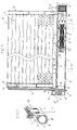
- a condenser module M in Fig. 1 includes a condenser casing G receiving a condenser part K and a sub-cooler part S which is formed as a prefabricated sub-cooler tube body R made from metal, particularly light metal like aluminium, which is separated from casing G, and which is provided below a lower side 4 of casing G with an intermediate gap 3 and at least substantially parallel to said lower side 4.
- Said sub-cooler tube body R consists of a round tube 1 and an outer structurally integrated longitudinal rib 2 (Fig. 2) which is substantially as thick as the casing G and protrudes beyond the outer circumference of said round tube 1.
- Said sub-cooler tube body R contains inside a free collector chamber B and a dryer equipment, i.e., by means of said sub-cooler tube body said sub-cooler part S is constituted with an integrated dryer.
- Said dryer equipment comprises in Fig. 1 a plug 6 which is inserted in sealing fashion into an end opening 5 and which unified by means of a spacer element 21 with a cage-like shell C such that it is positioning shell C within sub-cooler tube body R.
- a filter 22 is provided separated from shell C by a circumferential separation wall 23 sealingly co-acting with an inner wall 24 of sub-cooler tube body R.
- Shell C contains a desiccant charge D. Thanks to the separation wall 23 the refrigerant has to pass the desiccant charge D when flowing into and through filter 22.
- a head block 7 made from metal is secured as a cover of collector chamber B, expediently welded or brazed-at 15.
- a flow passage 8 extending into collector chamber B is formed within head block 7.
- Said passage 8 is open towards a connection 9 for a refrigerant pipe or an expansion valve, respectively.
- connection components can be mounted on head block 7.
- a further flow passage 11 is formed within head block 7 open towards a connection 12 for a refrigerant pipe and continued at its other side by a tube section 13.
- Tube section 13 connects via passage 11 connection 12 to an inlet E of condenser casing G.
- tube section 13 is brazed into head block 7 and into the condenser casing G, expediently simultaneously when brazing the condenser part K.
- a flow connection is provided formed by coupling tube 16 inserted into a fitting bore in condenser casing G and a lateral bore 18 of sub-cooler tube body R and brazed in place at locations 17, expediently simultaneously when brazing the condenser part K.
- Sub-cooler tube body R is secured to condenser casing G by holding brackets 19 (Fig. 2) which, e.g., are riveted at 25 and are brazed or welded to longitudinal rib 2. Said holding brackets 19 could be prolonged downwardly (indicated by dotted lines at 19') and could then be used as holding brackets for mounting the entire condenser module M.
- cooling fins F could be formed at the sub-cooler tube body R.
- said sub-cooler tube body R is an extruded profile section cut to the needed length, and to which head block 7 is brazed.
- Fig. 3 has the same prerequisites as Figs 1 and 2. Only the dryer equipment of dryer D provided within sub-cooler tube body R is different. Plug 6, by which the dryer equipment is positioned and sealed against the exterior is directly connected to filter 22 having separation wall 23 for co-action with inner wall 24. In continuation of filter 22 the desiccant charge D is received in a permeably bag 26 freely provided in the interior of sub-cooler tube body R.
- the dryer equipment can be inserted and positioned in sub-cooler tube body R with the help of plug 6 and can be removed for replacement with plug 6.
- the longitudinal extension of the sub-cooler tube body R substantially corresponds to the longitudinal extension of condenser casing G, i.e., sub-cooler part S protrudes both side surfaces of casing G only a little.
- a structure could be provided at which the sub-cooler tube body R is shorter than casing G.
- the dimension of sub-cooler tube body R in a direction according to the thickness of the casing G is somewhat larger than the thickness of the casing G.
- a further flow passage could be formed useable for e.g. mounting temperature or pressure sensor or the like.
Landscapes
- Engineering & Computer Science (AREA)
- Physics & Mathematics (AREA)
- Mechanical Engineering (AREA)
- Thermal Sciences (AREA)
- General Engineering & Computer Science (AREA)
- Air-Conditioning For Vehicles (AREA)
Priority Applications (2)
| Application Number | Priority Date | Filing Date | Title |
|---|---|---|---|
| EP00123153A EP1202007A1 (fr) | 2000-10-25 | 2000-10-25 | Condenseur et dessiccateur |
| US09/915,991 US6446464B1 (en) | 2000-10-25 | 2001-07-26 | Condenser module and dryer |
Applications Claiming Priority (1)
| Application Number | Priority Date | Filing Date | Title |
|---|---|---|---|
| EP00123153A EP1202007A1 (fr) | 2000-10-25 | 2000-10-25 | Condenseur et dessiccateur |
Publications (1)
| Publication Number | Publication Date |
|---|---|
| EP1202007A1 true EP1202007A1 (fr) | 2002-05-02 |
Family
ID=8170194
Family Applications (1)
| Application Number | Title | Priority Date | Filing Date |
|---|---|---|---|
| EP00123153A Withdrawn EP1202007A1 (fr) | 2000-10-25 | 2000-10-25 | Condenseur et dessiccateur |
Country Status (2)
| Country | Link |
|---|---|
| US (1) | US6446464B1 (fr) |
| EP (1) | EP1202007A1 (fr) |
Cited By (10)
| Publication number | Priority date | Publication date | Assignee | Title |
|---|---|---|---|---|
| DE10149798A1 (de) * | 2001-10-09 | 2003-04-10 | Behr Gmbh & Co | Kältemittelkondensator |
| WO2003081148A1 (fr) * | 2002-03-23 | 2003-10-02 | Behr Gmbh & Co. | Condenseur |
| DE10357176A1 (de) * | 2003-12-06 | 2005-06-30 | Modine Manufacturing Co., Racine | Kondensator |
| EP1562010A2 (fr) * | 2004-01-30 | 2005-08-10 | Behr GmbH & Co. | Echangeur de chaleur |
| EP1580499A2 (fr) * | 2004-03-17 | 2005-09-28 | SKG Italia S.p.A. | Cartouche pour condenseur, en particulier pour climatisation de véhicules |
| WO2005108896A1 (fr) * | 2004-05-05 | 2005-11-17 | Behr Gmbh & Co. Kg | Condenseur pour systeme de climatisation, notamment pour automobile |
| EP1637820A1 (fr) * | 2004-09-17 | 2006-03-22 | Behr France Hambach S.A.R.L. | Condenseur, en particulier pour installation de climatisation d'air de véhicules |
| DE102005021787A1 (de) * | 2005-05-11 | 2006-11-16 | Modine Manufacturing Co., Racine | Vorrichtung zur Behandlung des Kältemittels |
| DE102017116494A1 (de) * | 2017-07-21 | 2019-01-24 | Rupert Fertinger Gmbh | Trocknergehäuse und Herstellung eines Trocknergehäuses |
| EP3855101A1 (fr) * | 2020-01-22 | 2021-07-28 | Valeo Autosystemy SP. Z.O.O. | Échangeur de chaleur comportant un dispositif de séchage de récepteur positionné horizontalement |
Families Citing this family (14)
| Publication number | Priority date | Publication date | Assignee | Title |
|---|---|---|---|---|
| DE10251777A1 (de) * | 2002-11-05 | 2004-05-19 | Behr Gmbh & Co. | Sammelbehälter, Wärmetauscher und Kältemittelkreislauf |
| DE10336621A1 (de) * | 2003-08-05 | 2005-03-10 | Behr Gmbh & Co Kg | Kältemittelkondensator mit Trocknerflasche |
| ITTO20030768A1 (it) * | 2003-10-02 | 2005-04-03 | Denso Thermal Systems Spa | Condensatore per veicoli e corpo integrato radiatore- |
| US7478649B2 (en) * | 2004-06-30 | 2009-01-20 | Brasscorp Limited | Absorbent plugs and caps for air conditioning and refrigeration fittings |
| US20060070724A1 (en) * | 2004-10-06 | 2006-04-06 | Visteon Global Technologies, Inc. | Integrated receiver dryer sleeve |
| DE102005025451A1 (de) * | 2005-06-02 | 2006-12-07 | Denso Automotive Deutschland Gmbh | Kondensator für eine Klimaanlage |
| DE102005035344A1 (de) * | 2005-07-28 | 2007-02-01 | Modine Manufacturing Co., Racine | Entnahmevorrichtung für Trocknungsmittel |
| CN101634527B (zh) * | 2009-04-07 | 2013-02-20 | 三花控股集团有限公司 | 微通道换热器 |
| KR101771145B1 (ko) * | 2011-04-01 | 2017-08-24 | 한온시스템 주식회사 | 응축기 |
| US20150041414A1 (en) * | 2013-08-09 | 2015-02-12 | Ledwell & Son Enterprises, Inc. | Hydraulic fluid cooler and filter |
| DE102014002407B4 (de) * | 2014-02-20 | 2017-12-21 | Modine Manufacturing Company | Gelöteter Wärmetauscher |
| JP6575769B2 (ja) * | 2014-02-26 | 2019-09-18 | デンソー サーマル システムズ エス.ピー.エーDenso Thermal Systems S.P.A. | 冷却剤アキュムレータを有する横置き凝縮器 |
| JP6459799B2 (ja) * | 2014-06-30 | 2019-01-30 | 株式会社デンソー | 凝縮器 |
| US9983083B2 (en) * | 2014-10-16 | 2018-05-29 | Trensor, LLC | Climate control pressure plug with sensor |
Citations (10)
| Publication number | Priority date | Publication date | Assignee | Title |
|---|---|---|---|---|
| EP0480330A2 (fr) | 1990-10-04 | 1992-04-15 | Nippondenso Co., Ltd. | Appareil frigorifique avec modulateur |
| US5172758A (en) * | 1989-02-01 | 1992-12-22 | Sanden Corporation | Condenser with a built-in receiver |
| DE4319293A1 (de) | 1993-06-10 | 1994-12-15 | Behr Gmbh & Co | Klimaanlage für ein Fahrzeug |
| DE4402927A1 (de) | 1994-02-01 | 1995-08-03 | Behr Gmbh & Co | Kondensator für eine Klimaanlage eines Fahrzeuges |
| EP0689014A1 (fr) | 1994-06-22 | 1995-12-27 | Behr GmbH & Co. | Cartouche pour le condensateur d'un système de climatisation d'un véhicule |
| EP0769666A1 (fr) | 1995-10-18 | 1997-04-23 | Calsonic Corporation | Condenseur avec un réservoir à liquide |
| EP0854058A1 (fr) * | 1997-01-15 | 1998-07-22 | Deutsche Controls GmbH | Dispositif de conditionnement d'air pour véhicule et cartouche de séchage pour un dispositif de conditionnement d'air pour véhicule |
| JPH11257799A (ja) | 1998-03-06 | 1999-09-24 | Sanden Corp | 受液器一体型凝縮器 |
| EP0974793A2 (fr) | 1998-07-23 | 2000-01-26 | Sanden Corporation | Condenseur équipé avec un bouteille accumulatrice |
| DE20004438U1 (de) | 2000-03-09 | 2000-06-21 | S K G Italiana S P A | Filterpatrone und Kondensator |
Family Cites Families (5)
| Publication number | Priority date | Publication date | Assignee | Title |
|---|---|---|---|---|
| DE19712714A1 (de) * | 1997-03-26 | 1998-10-01 | Behr Gmbh & Co | Einsatz für ein Sammlerprofil eines Kondensators |
| JP3801348B2 (ja) * | 1997-07-28 | 2006-07-26 | 株式会社ヴァレオサーマルシステムズ | レシーバタンク |
| FR2770629B1 (fr) * | 1997-11-05 | 2000-02-11 | Valeo Thermique Moteur Sa | Condenseur de climatisation muni d'un reservoir de fluide interchangeable |
| US6223556B1 (en) * | 1999-11-24 | 2001-05-01 | Modine Manufacturing Company | Integrated parallel flow condenser receiver assembly |
| US6260379B1 (en) * | 1999-12-01 | 2001-07-17 | Visteon Global Technologies, Inc. | Condenser with integral receiver dryer |
-
2000
- 2000-10-25 EP EP00123153A patent/EP1202007A1/fr not_active Withdrawn
-
2001
- 2001-07-26 US US09/915,991 patent/US6446464B1/en not_active Expired - Fee Related
Patent Citations (11)
| Publication number | Priority date | Publication date | Assignee | Title |
|---|---|---|---|---|
| US5172758A (en) * | 1989-02-01 | 1992-12-22 | Sanden Corporation | Condenser with a built-in receiver |
| EP0480330A2 (fr) | 1990-10-04 | 1992-04-15 | Nippondenso Co., Ltd. | Appareil frigorifique avec modulateur |
| DE4319293A1 (de) | 1993-06-10 | 1994-12-15 | Behr Gmbh & Co | Klimaanlage für ein Fahrzeug |
| US5419141A (en) | 1993-06-10 | 1995-05-30 | Behr Gmbh & Co. | Air conditioner for a vehicle |
| DE4402927A1 (de) | 1994-02-01 | 1995-08-03 | Behr Gmbh & Co | Kondensator für eine Klimaanlage eines Fahrzeuges |
| EP0689014A1 (fr) | 1994-06-22 | 1995-12-27 | Behr GmbH & Co. | Cartouche pour le condensateur d'un système de climatisation d'un véhicule |
| EP0769666A1 (fr) | 1995-10-18 | 1997-04-23 | Calsonic Corporation | Condenseur avec un réservoir à liquide |
| EP0854058A1 (fr) * | 1997-01-15 | 1998-07-22 | Deutsche Controls GmbH | Dispositif de conditionnement d'air pour véhicule et cartouche de séchage pour un dispositif de conditionnement d'air pour véhicule |
| JPH11257799A (ja) | 1998-03-06 | 1999-09-24 | Sanden Corp | 受液器一体型凝縮器 |
| EP0974793A2 (fr) | 1998-07-23 | 2000-01-26 | Sanden Corporation | Condenseur équipé avec un bouteille accumulatrice |
| DE20004438U1 (de) | 2000-03-09 | 2000-06-21 | S K G Italiana S P A | Filterpatrone und Kondensator |
Non-Patent Citations (2)
| Title |
|---|
| PATENT ABSTRACTS OF JAPAN vol. 1999, no. 14 22 December 1999 (1999-12-22) * |
| PATENT ABSTRACTS OF JAPAN, vol. 1999, no. 14, 22 December 1999 (1999-12-22) |
Cited By (17)
| Publication number | Priority date | Publication date | Assignee | Title |
|---|---|---|---|---|
| US7043936B2 (en) | 2001-10-09 | 2006-05-16 | Behr Gmbh & Co. | Refrigerant condenser |
| DE10149798A1 (de) * | 2001-10-09 | 2003-04-10 | Behr Gmbh & Co | Kältemittelkondensator |
| WO2003081148A1 (fr) * | 2002-03-23 | 2003-10-02 | Behr Gmbh & Co. | Condenseur |
| US7121114B2 (en) | 2002-03-23 | 2006-10-17 | Behr Gmbh & Co., Kg | Condenser |
| DE10357176A1 (de) * | 2003-12-06 | 2005-06-30 | Modine Manufacturing Co., Racine | Kondensator |
| EP1562010A2 (fr) * | 2004-01-30 | 2005-08-10 | Behr GmbH & Co. | Echangeur de chaleur |
| EP1562010A3 (fr) * | 2004-01-30 | 2007-06-13 | Behr GmbH & Co. KG | Echangeur de chaleur |
| EP1580499A2 (fr) * | 2004-03-17 | 2005-09-28 | SKG Italia S.p.A. | Cartouche pour condenseur, en particulier pour climatisation de véhicules |
| EP1580499A3 (fr) * | 2004-03-17 | 2007-03-28 | SKG Italia S.p.A. | Cartouche pour condenseur, en particulier pour climatisation de véhicules |
| WO2005108896A1 (fr) * | 2004-05-05 | 2005-11-17 | Behr Gmbh & Co. Kg | Condenseur pour systeme de climatisation, notamment pour automobile |
| US7832230B2 (en) | 2004-05-05 | 2010-11-16 | Behr Gmbh & Co, Kg | Condenser for an air-conditioning system, particularly for a motor vehicle |
| EP1637820A1 (fr) * | 2004-09-17 | 2006-03-22 | Behr France Hambach S.A.R.L. | Condenseur, en particulier pour installation de climatisation d'air de véhicules |
| DE102005021787A1 (de) * | 2005-05-11 | 2006-11-16 | Modine Manufacturing Co., Racine | Vorrichtung zur Behandlung des Kältemittels |
| DE102017116494A1 (de) * | 2017-07-21 | 2019-01-24 | Rupert Fertinger Gmbh | Trocknergehäuse und Herstellung eines Trocknergehäuses |
| DE102017116494B4 (de) | 2017-07-21 | 2022-07-21 | Innerio Heat Exchanger GmbH | Trocknergehäuse und Herstellung eines Trocknergehäuses |
| EP3855101A1 (fr) * | 2020-01-22 | 2021-07-28 | Valeo Autosystemy SP. Z.O.O. | Échangeur de chaleur comportant un dispositif de séchage de récepteur positionné horizontalement |
| WO2021148536A1 (fr) * | 2020-01-22 | 2021-07-29 | Valeo Autosystemy Sp. Z O.O. | Échangeur de chaleur doté d'un séchoir récepteur positionné horizontalement |
Also Published As
| Publication number | Publication date |
|---|---|
| US6446464B1 (en) | 2002-09-10 |
| US20020046571A1 (en) | 2002-04-25 |
Similar Documents
| Publication | Publication Date | Title |
|---|---|---|
| EP1202007A1 (fr) | Condenseur et dessiccateur | |
| US5537839A (en) | Condenser with refrigerant drier | |
| JP3629819B2 (ja) | 受液器一体型凝縮器 | |
| US3212289A (en) | Combination accumulator and receiver | |
| KR100485100B1 (ko) | 수액기일체형응축기 | |
| US6185959B1 (en) | Refrigerant system components with cartridge type thermal expansion valve and method of making same | |
| EP0689016B1 (fr) | Accumulateur pour un système de conditionnement d'air | |
| JP4719555B2 (ja) | 熱交換器 | |
| US6334333B1 (en) | Condenser | |
| CN105299977A (zh) | 用于换热器的接收器、以及装备有接收器的换热器 | |
| WO2002001124A1 (fr) | Echangeur de chaleur et ensemble echangeur de chaleur/vanne de detente | |
| JP6850060B2 (ja) | コンデンサ | |
| EP1070612A2 (fr) | Condenseur | |
| JP4513241B2 (ja) | 減圧装置 | |
| US6606879B1 (en) | Accumulator assembly having a reversing valve and a heat pump system thereof | |
| EP3708928A1 (fr) | Échangeur de chaleur avec filtre, pour boucle de fluide réfrigérant | |
| JP3966090B2 (ja) | 受液器一体型凝縮器 | |
| US20050120739A1 (en) | Integrated condenser/receiver | |
| ITTO981094A1 (it) | Condensatore per impianti di condizionamento d'aria per veicoli, condispositivo di espansione integrato. | |
| JP3840624B2 (ja) | 自動車用空調装置のコンデンサ | |
| JP3250006B2 (ja) | オイルフィルタカートリッジを備えたエンジン | |
| JP2000018772A (ja) | レシーバータンク付きコンデンサ | |
| US20240133601A1 (en) | Fluid collector | |
| JP2019070503A (ja) | 受液器およびこれを用いたコンデンサ | |
| JP2002372341A (ja) | 冷凍サイクルの受液器および受液器一体型凝縮器 |
Legal Events
| Date | Code | Title | Description |
|---|---|---|---|
| PUAI | Public reference made under article 153(3) epc to a published international application that has entered the european phase |
Free format text: ORIGINAL CODE: 0009012 |
|
| 17P | Request for examination filed |
Effective date: 20010709 |
|
| AK | Designated contracting states |
Kind code of ref document: A1 Designated state(s): DE ES FR IT Kind code of ref document: A1 Designated state(s): AT BE CH CY DE DK ES FI FR GB GR IE IT LI LU MC NL PT SE |
|
| AX | Request for extension of the european patent |
Free format text: AL;LT;LV;MK;RO;SI |
|
| AKX | Designation fees paid |
Free format text: DE ES FR IT |
|
| RAP1 | Party data changed (applicant data changed or rights of an application transferred) |
Owner name: FINBER S.P.A |
|
| 17Q | First examination report despatched |
Effective date: 20090120 |
|
| STAA | Information on the status of an ep patent application or granted ep patent |
Free format text: STATUS: THE APPLICATION IS DEEMED TO BE WITHDRAWN |
|
| 18D | Application deemed to be withdrawn |
Effective date: 20100501 |