EP1741838A2 - Verfahren zum Vorbereiten eines Pfahls mit Füllungselemente sowie Pfahl - Google Patents
Verfahren zum Vorbereiten eines Pfahls mit Füllungselemente sowie Pfahl Download PDFInfo
- Publication number
- EP1741838A2 EP1741838A2 EP06076388A EP06076388A EP1741838A2 EP 1741838 A2 EP1741838 A2 EP 1741838A2 EP 06076388 A EP06076388 A EP 06076388A EP 06076388 A EP06076388 A EP 06076388A EP 1741838 A2 EP1741838 A2 EP 1741838A2
- Authority
- EP
- European Patent Office
- Prior art keywords
- pile
- fill element
- fill
- mould
- concrete
- Prior art date
- Legal status (The legal status is an assumption and is not a legal conclusion. Google has not performed a legal analysis and makes no representation as to the accuracy of the status listed.)
- Withdrawn
Links
Images


Classifications
-
- B—PERFORMING OPERATIONS; TRANSPORTING
- B28—WORKING CEMENT, CLAY, OR STONE
- B28B—SHAPING CLAY OR OTHER CERAMIC COMPOSITIONS; SHAPING SLAG; SHAPING MIXTURES CONTAINING CEMENTITIOUS MATERIAL, e.g. PLASTER
- B28B23/00—Arrangements specially adapted for the production of shaped articles with elements wholly or partly embedded in the moulding material; Production of reinforced objects
- B28B23/0068—Embedding lost cores
-
- B—PERFORMING OPERATIONS; TRANSPORTING
- B28—WORKING CEMENT, CLAY, OR STONE
- B28B—SHAPING CLAY OR OTHER CERAMIC COMPOSITIONS; SHAPING SLAG; SHAPING MIXTURES CONTAINING CEMENTITIOUS MATERIAL, e.g. PLASTER
- B28B23/00—Arrangements specially adapted for the production of shaped articles with elements wholly or partly embedded in the moulding material; Production of reinforced objects
- B28B23/02—Arrangements specially adapted for the production of shaped articles with elements wholly or partly embedded in the moulding material; Production of reinforced objects wherein the elements are reinforcing members
- B28B23/04—Arrangements specially adapted for the production of shaped articles with elements wholly or partly embedded in the moulding material; Production of reinforced objects wherein the elements are reinforcing members the elements being stressed
- B28B23/12—Arrangements specially adapted for the production of shaped articles with elements wholly or partly embedded in the moulding material; Production of reinforced objects wherein the elements are reinforcing members the elements being stressed to form prestressed circumferential reinforcements
- B28B23/14—Arrangements specially adapted for the production of shaped articles with elements wholly or partly embedded in the moulding material; Production of reinforced objects wherein the elements are reinforcing members the elements being stressed to form prestressed circumferential reinforcements by wrapping, e.g. winding, apparatus
-
- B—PERFORMING OPERATIONS; TRANSPORTING
- B28—WORKING CEMENT, CLAY, OR STONE
- B28B—SHAPING CLAY OR OTHER CERAMIC COMPOSITIONS; SHAPING SLAG; SHAPING MIXTURES CONTAINING CEMENTITIOUS MATERIAL, e.g. PLASTER
- B28B23/00—Arrangements specially adapted for the production of shaped articles with elements wholly or partly embedded in the moulding material; Production of reinforced objects
- B28B23/02—Arrangements specially adapted for the production of shaped articles with elements wholly or partly embedded in the moulding material; Production of reinforced objects wherein the elements are reinforcing members
- B28B23/18—Arrangements specially adapted for the production of shaped articles with elements wholly or partly embedded in the moulding material; Production of reinforced objects wherein the elements are reinforcing members for the production of elongated articles
-
- E—FIXED CONSTRUCTIONS
- E02—HYDRAULIC ENGINEERING; FOUNDATIONS; SOIL SHIFTING
- E02D—FOUNDATIONS; EXCAVATIONS; EMBANKMENTS; UNDERGROUND OR UNDERWATER STRUCTURES
- E02D5/00—Bulkheads, piles, or other structural elements specially adapted to foundation engineering
- E02D5/02—Sheet piles or sheet pile bulkheads
- E02D5/03—Prefabricated parts, e.g. composite sheet piles
- E02D5/10—Prefabricated parts, e.g. composite sheet piles made of concrete or reinforced concrete
-
- E—FIXED CONSTRUCTIONS
- E02—HYDRAULIC ENGINEERING; FOUNDATIONS; SOIL SHIFTING
- E02D—FOUNDATIONS; EXCAVATIONS; EMBANKMENTS; UNDERGROUND OR UNDERWATER STRUCTURES
- E02D5/00—Bulkheads, piles, or other structural elements specially adapted to foundation engineering
- E02D5/22—Piles
- E02D5/24—Prefabricated piles
- E02D5/30—Prefabricated piles made of concrete or reinforced concrete or made of steel and concrete
-
- E—FIXED CONSTRUCTIONS
- E02—HYDRAULIC ENGINEERING; FOUNDATIONS; SOIL SHIFTING
- E02D—FOUNDATIONS; EXCAVATIONS; EMBANKMENTS; UNDERGROUND OR UNDERWATER STRUCTURES
- E02D5/00—Bulkheads, piles, or other structural elements specially adapted to foundation engineering
- E02D5/22—Piles
- E02D5/52—Piles composed of separable parts, e.g. telescopic tubes ; Piles composed of segments
- E02D5/523—Piles composed of separable parts, e.g. telescopic tubes ; Piles composed of segments composed of segments
Definitions
- the present invention relates to a method for manufacturing a pile; to a pile obtainable with this method and to a pile.
- the present invention has for its object to provide a solution to the above stated problems.
- a first aspect of the present invention therefore relates to a method for preparing a pile, comprising the steps of:
- An advantage of this method is that a pile with an acceptable structural strength can be manufactured wherein less concrete need be used than in a conventional solid pile. This has a favourable effect on the production cost of the pile and on the environmental impact resulting from the production process.
- the fill element is preferably positioned such that it is situated centrally in the pile to be formed.
- the fill element comprises a plastic foam material, such as for instance a polystyrene foam.
- a plastic foam material such as for instance a polystyrene foam.
- An advantage of the use of such materials is that they are relatively light but can also withstand the pressure of the poured concrete. This prevents considerable differences occurring in the thickness of the wall of the pile along its length.
- the plastic foam is preferably in the form of an already solid foam which can be brought into a desired shape which it also substantially retains during pouring of the concrete.
- the positioning means preferably comprise a fixing element extending in longitudinal direction of the mould, wherein during the performing of step i) the fill element is arranged on or round the fixing element.
- a fixing element extending in longitudinal direction of the mould, wherein during the performing of step i) the fill element is arranged on or round the fixing element.
- the positioning means comprises at least one spacer, wherein the fill element is positioned before or during performing of step ii) of the method according to the invention.
- the fill element can be positioned relatively quickly and easily at the correct location in the pile to be formed.
- the fill element can be positioned during pouring of the concrete due to the presence of the spacers, which are preferably of plastic. Through the pouring of the concrete the fill element will generally begin to float, at least move toward the top side of the mould. By arranging spacers in the mould this upward directed movement of the fill element is stopped, and the fill element is positioned.
- a plurality of spacers are preferably used to position the fill element.
- the spacers can be provided with a clamping part with which they can be fixed for instance to the reinforcement and/or mould of the pile.
- the spacer is fixed to the reinforcement of the pile to be formed. It is particularly recommended here that it is fixed to longitudinal reinforcement of the pile. It is further also possible for the spacers to be (removably) fixed to the mould or a mould cover extending over the top side of the mould.
- a mould cover preferably comprises a metal plate or pin.
- the spacers are placed partially in the fill element. It is then recommended that the fill element comprises a plastic foam material, such as for instance recycled polystyrene or expanded polystyrene.
- the portion of the spacer extending into the fill element is then preferably provided with a barbed profile such that a good connection is obtained between the fill element and the spacer.
- the spacer is in this case preferably supported by a mould cover.
- the positioning means substantially centre the fill element in the pile to be formed.
- a pile is hereby obtained which very readily absorbs the forces during inter alia pile-driving. In addition less concrete is necessary, this resulting in reduced production cost and less of an environmental impact.
- the positioning means comprise a fixing element extending in longitudinal direction as well as spacers. A good fixation of the fill element in the mould is thus obtained.
- the fill element is preferably manufactured from material with a lower specific mass than cured concrete.
- the fill element extends substantially along the whole length of the mould.
- An advantage hereof is that even less concrete need be used. This has a favourable effect on production cost and on environmental impact.
- the fill element is of elongate form.
- the fill element comprises separate parts.
- the advantage hereof is that people involved in the manufacture of the pile can relatively easily arrange the fill element, at least the separate parts thereof, on the fixing element (or spacers).
- the fill element is then relatively easy to transport. This is particularly recommended when the pile is relatively long.
- the fill element is constructed from a number of fill element parts placed successively with intermediate spacing.
- the intermediate spaces are herein filled with concrete during pouring.
- the structural stiffness of the pile can be adjusted as required by variation of the number, the positions and/or the dimensions of the intermediate spaces.
- the spacers extend through the intermediate spaces so that the spacers can rest on the fixing element instead of on the fill element.
- the fixing element preferably comprises a soft steel rod, a prestressed steel wire, a prestressed steel strand or a prestressed plastic wire.
- the fill element is preferably arranged at a distance from a first outer end and/or a second outer end of the mould such that at least one solid end of the pile is formed when the concrete is poured.
- the advantage hereof is that a solid head and/or foot of the pile is obtained in this manner which can withstand relatively great loads during pile-driving.
- An additional advantage is that no earth can enter the pile during pile-driving.
- the fill element is rod-like and is provided with a slot extending in the longitudinal direction for arranging the fill element on or round the fixing element.
- the fill element can be arranged very quickly by means of such a slot.
- the slot width of the fill element is greater than the transverse dimension of the fixing element.
- the fill element can hereby be arranged quickly and easily on or round the fixing element, and can also be displaced.
- the slot of the fill element is pushed over the fixing element such that the fill element is substantially centred in the pile to be formed, and wherein the fill element is rotated before or during pouring of the concrete such that the fill element is fixed on the fixing element during the pouring.
- Fixing is here understood to mean, among other things, that the fill element cannot float upward during the pouring.
- longitudinal reinforcement is arranged in the mould prior to the performing of step ii) of the method according to the invention such that the longitudinal reinforcement is incorporated in the concrete.
- Such longitudinal reinforcement results in a reduced chance of the pile breaking during transport and pile-driving.
- spiral reinforcement is arranged at least at one end of the mould. Through the arranging of such spiral reinforcement the end of the pile is better able to withstand the relatively great loads during pile-driving.
- a reinforcing band extending along the inner periphery of the mould is arranged at least at one end of the mould.
- a reinforcing band is preferably of metal.
- An advantage of such a band is that it can be placed relatively easily in the mould.
- An additional advantage is that the band can also be arranged after curing of the pile.
- a further advantage of such a band is that a head or a foot is obtained which can withstand the relatively great loads during pile-driving.
- the fill element preferably comprises a tube.
- the advantage of such a fill element is that it is relatively strong, whereby a relatively large amount of concrete can be poured onto it without it being compressed. In addition, relatively little material is required to manufacture a fill element of a relatively large size.
- the fill element is a tube, wherein at least a portion of the inner side of the tube is provided with a securing element extending over the inner periphery of the tube.
- the securing element comprises a plastic foam material such as polystyrene foam.
- the securing element can then be arranged on or round the fixing element such that the tube is positioned.
- the securing element is a plastic cylinder, the wall of which is in clamping contact with the inner wall of the tube.
- the concrete in step ii) comprises broken concrete granulate, this resulting in a relatively small environmental impact since broken concrete granulate can be reused.
- a metal band extending along the periphery of the pile is arranged after performing step iii). It is particularly recommended here that the pile is substantially cured.
- a second aspect of the present invention relates to a pile obtainable with the above described method.
- a third aspect of the present invention relates to a pile comprising a casing of cured concrete and a core extending in longitudinal direction of the pile, which core comprises a plastic fill element.
- Such a pile comprises relatively little concrete.
- the cost price of such a pile is hereby relatively low.
- Such a pile further has less of an environmental impact since it comprises less concrete than a solid pile.
- the fill element comprises a plastic foam material such as polystyrene foam.
- a plastic foam material such as polystyrene foam.
- Such material is relatively light and well able to withstand compression, whereby a pile is obtained with a diameter of the core which is substantially the same everywhere.
- the fill element has a substantially round, polygonal such as octagonal or rectangular form.
- the fill element is rod-like.
- the fill element is provided with a slot which extends in longitudinal direction of the fill element and which is used to arrange the fill element on the fixing element.
- the slot preferably extends as far as or beyond the centre of gravity of the fill element. If the fixing element is removed after preparation of the pile, this slot can be used for different purposes, such as for instance concrete core activating purposes. Particularly when a plastic foam material is used, the core can then serve as insulating/protective material for a conduit arranged through the slot.
- the slot width is smaller than the transverse dimension of the fixing element.
- the advantage hereof is that the fill element can be arranged relatively easily on the fixing element and, if necessary, can be rotated more easily. Close to the end of the slot the slot width is preferably greater than the transverse dimension of the fixing element. The fill element can hereby be arranged even more easily on the fixing element and held at the desired position.
- At least one end of the pile is provided with a concrete closure.
- the advantage of such a closure is that a head and/or foot of the pile is obtained which can withstand relatively great loads during pile-driving.
- An additional advantage is that no earth can penetrate into the pile during pile-driving.
- the core is provided with a fixing element extending in longitudinal direction of the pile.
- a fixing element extending in longitudinal direction of the pile.
- Figure 1 shows a view of a mould 1 for preparing a pile according to the invention.
- a fixing element 2 is arranged in longitudinal direction for the purpose of fixing a fill element 4 (not shown).
- Mould 1 is further provided with longitudinal reinforcement 3 extending in lengthwise direction of mould 1. This longitudinal reinforcement 3 ensures that the chance of the pile breaking during transport and pile-driving is reduced.
- Figure 2 shows the mould of Figure 1, wherein a fill element 4, preferably of polystyrene foam, is arranged round fixing element 2.
- Fill element 4 is provided along the whole length with a slot 5. It is possible to slide fill element 4 over the fixing element through this slot 5.
- Slot 5 extends inward at least to a position beyond the centre of gravity 6 of the fill element.
- the fill element is rotated such that opening 8 of slot 5 is directed toward the upper side of mould 1.
- Figure 3 shows pouring of concrete 7 in mould 1.
- the pile is given the desired form by means of walls 9 and 10 and bottom 11 of the mould. Possible shapes are, among others, square, pentagonal, hexagonal, octagonal or round.
- the longitudinal reinforcement 3 and fill element 4 are wholly enclosed by the concrete 7 during the pouring.
- Fixing element 2 here ensures that fill element 4 does not displace to the top side of the mould, or only does so to a limited extent.
- Pouring of concrete 7 continues until the upper edge of walls 9 and 10 is reached. The whole is then allowed to cure for some time.
- the mould is optionally provided with a mould cover (not shown) extending along the top side of the mould.
- FIG. 4 shows a pile 12 according to the invention.
- Pile 12 is provided with a fill element 13 extending in longitudinal direction of the pile, wherein the fill element is enclosed by a casing 14 of cured concrete.
- Fill element 13 consists of a number of separate parts 13a and 13b, whereby the fill element can be arranged relatively easily during preparation of pile 12.
- the fixing element 15 is visible that has served to hold fill element 13 in its position. It is however possible to remove this fixing element 15 during or after curing of pile 12.
- Pile 12 is further provided with longitudinal reinforcement 16 in order to ensure a reduced chance of pile 12 breaking during transport and pile-driving.
- FIG. 5 shows a cross-section of pile 12 of Figure 4.
- the fill element 13 is enclosed by a concrete casing 14.
- Longitudinal reinforcement 16 is incorporated in this concrete casing.
- Fill element 13 is provided with a slot 17 extending up to the centre of gravity 18 of the fill element.
- Fill element 13 lies against fixing element 15.
- Fixing element 15 and fill element 13 are positioned during preparation of pile 12 such that fill element 13 is situated centrally in pile 12. Further indicated are optional spacers 19 remaining on the outer surface of fill element 13 which further contribute toward the fill element 13 being held at the desired position during preparation of pile 12.
- the use of only a fixing element 15 is however also possible.
- Figure 6 shows an embodiment of the invention wherein spacers 20 and 21 are used to position fill element 22 during preparation of pile 23.
- Spacers 20 are connected to longitudinal reinforcement 24 extending in lengthwise direction of pile 23.
- the spacer 21 was connected to a mould cover arranged on the top side of mould 25 (not shown).
- Spacers 20 can optionally be used separately or spacer(s) 21 can be used separately. It is however recommended to use them together.
- FIG. 7 shows another preferred embodiment of a pile 26 according to the invention.
- Pile 26 is provided with a fill element 27 situated in the core of pile 26.
- This fill element 27 is here enclosed by a concrete casing 28.
- This fill element 27 consists of a tube 29, preferably of plastic, which is provided at one end with a securing element 31 extending along inner wall 30 of the tube.
- This securing element 31 is preferably manufactured from metal or plastic.
- Securing element 31 herein lies close-fittingly against inner wall 30 of tube 29.
- Spacers 34 and/or 35 are optionally arranged in order to further ensure that tube 29 is held centrally in the pile 26 to be formed during preparation of the pile.
- Spacers 34 are attached to longitudinal reinforcement 33 of pile 26, spacer 35 having been connected to the mould and/or mould cover (not shown) during preparation of the pile. During preparation of pile 26 the tube 29 comes to lie against these spacers 34 and/or 35, whereby tube 29 can be positioned precisely.
- Figure 8 shows a cross-section of pile 26 of Figure 7.
- Tube 29 is situated centrally in pile 26.
- a securing element 31 is arranged in tube 29.
- This securing element 31 is arranged round fixing element 32.
- Tube 29 is enclosed by a casing 28 of cured concrete.
- Longitudinal reinforcement 33 is arranged in this casing 28 for additional strength during transport.
- Spacers 34 and/or 35 are further received in concrete casing 28. These spacers 34 and/or 35 are used during manufacture to position tube 29 centrally in pile 26.
- Figure 9 shows a pile 36 according to a further embodiment of the present invention.
- the fill element herein comprises a tube 37, preferably of plastic.
- Tube 37 is enclosed by a concrete casing 38.
- Longitudinal reinforcement 39 is received in this concrete casing 38.
- This longitudinal reinforcement 39 extends in the lengthwise direction of pile 36 and reduces the chance of pile 36 breaking during transport and pile-driving.
- Spacers 40 and 41 are further provided. These spacers 40 and/or 41 are used during manufacture of pile 36 to position tube 37 centrally in pile 36.
- Figure 10 shows a pile 42 according to the invention.
- This pile 42 is open on the top side such that fill element 43, which is situated centrally in pile 42, can be seen.
- This fill element 43 is enclosed by a concrete casing 44.
- the upper end and/or the lower end of the pile is provided with a reinforcing band 45 extending in peripheral direction of pile 42.
- FIG 11 shows a cross-section of pile 42 of Figure 10.
- Pile 42 herein comprises a fill element 43 extending along a fixing element 46.
- Fill element 43 is enclosed by a concrete casing 44 incorporating longitudinal reinforcement 47.
- the head of the pile is however open, at least fill element 43 is visible from outside.
- a reinforcing band 45 extending along the periphery of the pile is arranged in the head, close to the end of the pile.
- FIG 12 shows a recommended embodiment of the present invention.
- Pile 48 herein comprises a concrete closure 49 (not shown) which ensures that a solid head 50 and/or foot is formed.
- the pile is further provided with a concrete casing 51.
- FIG 13 shows pile 48 of Figure 12 in cross-section.
- Pile 48 is provided with a solid head 50 and a concrete casing 51 provided with longitudinal reinforcement 52.
- a fill element 53 also extends in longitudinal direction of pile 48.
- the concrete closure 54 is preferably integrated with the concrete casing 51 of pile 48. Owing to this solid head 50 pile 48 is better able to withstand the relatively great forces during pile-driving.
- Pile 48 is preferably further provided in head 50 and/or the foot with so-called spiral reinforcement 54. This spiral reinforcement 54 makes head 50 still better able to withstand the great forces during pile-driving.
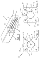
- Figure 14 shows a long mould 55 wherein the mould is divided into a number of sub-moulds 56. Sub-moulds 56 are separated from each other by means of end surface partitions 57. A plurality of concrete piles can be prepared in a batch by making use of such a long mould 55. Longitudinal reinforcement 58 and fill elements 59 are arranged in sub-moulds 56. These fill elements are positioned using a fixing element 60 (not shown).
- Figure 15 shows a further preferred embodiment of the invention. This embodiment greatly resembles the embodiment shown in figure 5 and a detailed description thereof will not therefore be given.
- the embodiment of figure 15 shows a fill element with an octagonal cross-section which is enclosed by a concrete casing 64 which incorporates longitudinal reinforcement 66.
- Fill element 63 is provided with a slot 17 so that the fill element can be pushed over fixing element 15.
- spacers 69 do not rest on the outer surface of fill element 63 but are extended to a position against the central fixing element 15.
- Spacers 69 are herein arranged at the position of the intermediate spaces between the separate parts of fill element 63. Because spacers 69 rest on fixing element 15, less stringent structural requirements need be made of the material of fill element 63.
- the material of fill element 13 must after all have a strength such that the underside of the respective spacers 19 do not cause any damage to the outer surface of fill element 13.
- five spacers 69 are arranged in the embodiment shown in figure 15. In other embodiments (not shown) this number can however be smaller, as discussed above with reference to other embodiments of the invention.
- Figure 16 shows a further preferred embodiment which largely corresponds with the embodiment shown in figure 6.
- no fixing element 15 is arranged in fill element 73 of octagonal cross-section 9.
- fill element 73 is held in position by spacers 74 resting on one side on the outer surface 72 of fill element 73 and/or attached on the other side to longitudinal reinforcement 39.
- five spacers 74 are once again shown. An application with the small number of spacers does however fall wholly within the reach of the skilled person.
- FIG 17 shows a further preferred embodiment of the present invention.
- no fixing element is arranged in fill element 79.
- Fill element 79 is held in position in this embodiment by a spacer 75 extending in fill element 79, wherein spacer 75 is provided at the end extending in fill element 75 (preferably of recycled polystyrene foam) with a barbed profile 80 such that it is firmly connected to fill element 75.
- the other end 81 of spacer 75 supports against a so-called mould cover (not shown), such as for instance a pin which extends transversely of the longitudinal direction of the mould and which is connected to the top side of the longitudinal walls of the mould. This prevents fill element 79 floating upward during pouring of the concrete.
- spacers 77 can also be used which are attached to longitudinal reinforcement 76. An even better fixation of fill element 79 in the mould is thus obtained.
Landscapes
- Engineering & Computer Science (AREA)
- Structural Engineering (AREA)
- Chemical & Material Sciences (AREA)
- Life Sciences & Earth Sciences (AREA)
- Mechanical Engineering (AREA)
- Ceramic Engineering (AREA)
- Manufacturing & Machinery (AREA)
- General Life Sciences & Earth Sciences (AREA)
- Mining & Mineral Resources (AREA)
- Paleontology (AREA)
- Civil Engineering (AREA)
- General Engineering & Computer Science (AREA)
- Composite Materials (AREA)
- Piles And Underground Anchors (AREA)
Applications Claiming Priority (2)
| Application Number | Priority Date | Filing Date | Title |
|---|---|---|---|
| NL1029468A NL1029468C2 (nl) | 2005-07-08 | 2005-07-08 | Werkwijze voor het vervaardigen van een heipaal met vulelementen. |
| NL1030631A NL1030631C2 (nl) | 2005-07-08 | 2005-12-09 | Werkwijze voor het vervaardigen van een heipaal met vulelementen (pluspaal). |
Publications (2)
| Publication Number | Publication Date |
|---|---|
| EP1741838A2 true EP1741838A2 (de) | 2007-01-10 |
| EP1741838A3 EP1741838A3 (de) | 2015-04-01 |
Family
ID=37137553
Family Applications (1)
| Application Number | Title | Priority Date | Filing Date |
|---|---|---|---|
| EP06076388.5A Withdrawn EP1741838A3 (de) | 2005-07-08 | 2006-07-10 | Verfahren zum Vorbereiten eines Pfahls mit Füllungselemente sowie Pfahl |
Country Status (2)
| Country | Link |
|---|---|
| EP (1) | EP1741838A3 (de) |
| NL (2) | NL1029468C2 (de) |
Cited By (5)
| Publication number | Priority date | Publication date | Assignee | Title |
|---|---|---|---|---|
| NL2001264C2 (nl) * | 2008-02-07 | 2009-08-10 | Hanenberg Wegenbouw B V | Bandelement voor het aanbrengen van begrenzingen in een bestrating. |
| ITPD20080329A1 (it) * | 2008-11-12 | 2010-05-13 | Lucio Pedrocco | Palancola in calcestruzzo armato precompresso, metodo di produzione di tale palancola e parete comprendente una pluralità di tali palancole |
| FR3033514A1 (fr) * | 2015-03-12 | 2016-09-16 | Conseil Service Investissements | Procede de moulage d'elements tubulaires en materiau comportant du ciment et pieu ainsi obtenu |
| NL2019619A (nl) * | 2016-09-22 | 2018-03-27 | Oskar Peter Henriette Pudelko | Funderingwerkwijze, funderingkolomdeel en trillingabsorptie-orgaan |
| NL2019370B1 (nl) * | 2017-07-28 | 2019-02-19 | Berton Holding B V | Werkwijze voor het vervaardigen van een langwerpige schuttingpaal |
Families Citing this family (1)
| Publication number | Priority date | Publication date | Assignee | Title |
|---|---|---|---|---|
| NL2002150C (nl) * | 2008-10-29 | 2010-05-03 | Univ Eindhoven Tech | Bekistingsmodule en werkwijze voor het vervaardigen van een fundering. |
Family Cites Families (9)
| Publication number | Priority date | Publication date | Assignee | Title |
|---|---|---|---|---|
| GB357043A (en) * | 1931-01-16 | 1931-09-17 | Samuel Williams And Sons Ltd | Improvements in concrete piles |
| US2274082A (en) * | 1939-08-31 | 1942-02-24 | Standard Oil Dev Co | Method for construction of marine foundations |
| GB537736A (en) * | 1939-12-27 | 1941-07-04 | Prenton Brick And Tile Company | Improvements in and relating to hollow mouldable articles |
| FR875253A (fr) * | 1941-08-14 | 1942-09-14 | Elin Ag Fu R Elek Sche Ind | Procédé pour la constitution de piliers creux en beton armé, bétonnés en position verticale, notamment pour lignes électriques aériennes |
| GB715563A (en) * | 1952-06-23 | 1954-09-15 | Ferdinand William Berry | Improvements in spacer members for the reinforcement of reinforced concrete |
| SE423877B (sv) * | 1977-02-07 | 1982-06-14 | A Betong Ab | Sett att gjuta tunnveggiga ihaliga betongstolpar och form for utforande av settet |
| AU499615B2 (en) * | 1977-02-11 | 1979-04-26 | Nippon Concrete Kogyo K.K. | Concrete pile orthe like structure |
| JPH0321718A (ja) * | 1989-06-17 | 1991-01-30 | Chugoku Concrete Kogyo Kk | 軟弱地盤用基礎杭 |
| WO1994027002A1 (fr) * | 1993-05-18 | 1994-11-24 | Senji Yamashita | Element de moulage souple et procede de realisation d'un trou traversant au moyen dudit element de moulage |
-
2005
- 2005-07-08 NL NL1029468A patent/NL1029468C2/nl not_active IP Right Cessation
- 2005-12-09 NL NL1030631A patent/NL1030631C2/nl not_active IP Right Cessation
-
2006
- 2006-07-10 EP EP06076388.5A patent/EP1741838A3/de not_active Withdrawn
Cited By (7)
| Publication number | Priority date | Publication date | Assignee | Title |
|---|---|---|---|---|
| NL2001264C2 (nl) * | 2008-02-07 | 2009-08-10 | Hanenberg Wegenbouw B V | Bandelement voor het aanbrengen van begrenzingen in een bestrating. |
| EP2088241A1 (de) * | 2008-02-07 | 2009-08-12 | Hanenberg Wegenbouw B.V. | Randsteinelement zur Strassenbegrenzung |
| ITPD20080329A1 (it) * | 2008-11-12 | 2010-05-13 | Lucio Pedrocco | Palancola in calcestruzzo armato precompresso, metodo di produzione di tale palancola e parete comprendente una pluralità di tali palancole |
| FR3033514A1 (fr) * | 2015-03-12 | 2016-09-16 | Conseil Service Investissements | Procede de moulage d'elements tubulaires en materiau comportant du ciment et pieu ainsi obtenu |
| NL2019619A (nl) * | 2016-09-22 | 2018-03-27 | Oskar Peter Henriette Pudelko | Funderingwerkwijze, funderingkolomdeel en trillingabsorptie-orgaan |
| WO2018084697A1 (en) * | 2016-09-22 | 2018-05-11 | Pudelko Oskar Peter Henriette | Foundation method, foundation column part, and vibration absorption member |
| NL2019370B1 (nl) * | 2017-07-28 | 2019-02-19 | Berton Holding B V | Werkwijze voor het vervaardigen van een langwerpige schuttingpaal |
Also Published As
| Publication number | Publication date |
|---|---|
| NL1029468C2 (nl) | 2007-01-09 |
| NL1030631C2 (nl) | 2007-01-09 |
| EP1741838A3 (de) | 2015-04-01 |
Similar Documents
| Publication | Publication Date | Title |
|---|---|---|
| KR101713632B1 (ko) | 튜브형 고무몰드를 활용한 중공 피씨슬래브 및 이의 제조방법 | |
| CN108457421B (zh) | 一种装配式钢筋混凝土u形框架梁的制作模具和制作方法 | |
| CN107735535B (zh) | 用于支承混凝土建筑中的加固件的可堆叠的墙壁间隔件 | |
| EP1741838A2 (de) | Verfahren zum Vorbereiten eines Pfahls mit Füllungselemente sowie Pfahl | |
| KR101349297B1 (ko) | 보강철근에 의한 부분 보강 구조의 콘크리트 합성 강관말뚝 및 그 제작방법 | |
| US20130097955A1 (en) | Precast concrete pile with carbon fiber reinforced grid | |
| KR102120647B1 (ko) | 가공석재와 콘크리트의 합성블록 및 그 제작방법 | |
| EP3006639A1 (de) | Modul für gebäudedecken und verfahren zur herstellung dieses moduls | |
| CN210791468U (zh) | 一种混凝土预制件脱模设备 | |
| CN213448425U (zh) | 一种带沟槽的铆钉预制桩 | |
| KR101530039B1 (ko) | 중공체 및 중공 슬래브 시공용 프리캐스트 콘크리트 슬래브 | |
| CN210238488U (zh) | 一种混凝土桩体结构 | |
| KR102354464B1 (ko) | 용접철망을 구비하는 멀티리브 pc 슬래브 및 멀티리브 pc 슬래브의 제작 및 시공 방법 | |
| KR100508532B1 (ko) | 속빈 슬래브교의 구조 | |
| CN102409846B (zh) | 一种建筑用空心楼板模板及其拼装方法 | |
| CN202187552U (zh) | 一种楼梯间平台模板支撑系统的钢管底座 | |
| CN201011027Y (zh) | 组合式一次性填充模板 | |
| EP3017124B1 (de) | Zuführvorrichtung | |
| CN218149783U (zh) | 一种免支模设备基础预留螺栓孔洞的施工结构 | |
| CN222513200U (zh) | 一种建筑施工的桩基结构 | |
| CN220667147U (zh) | 一种薄壁高刚度水泥杆 | |
| US20170072590A1 (en) | Post with metal cage reinforcement and method for manufacturing same | |
| CN218462503U (zh) | 一种便于排气的芯模 | |
| JP2011148530A (ja) | プレストレストコンクリート構造物 | |
| KR102546462B1 (ko) | 스페이서를 이용한 중공 슬래브 구조 |
Legal Events
| Date | Code | Title | Description |
|---|---|---|---|
| PUAI | Public reference made under article 153(3) epc to a published international application that has entered the european phase |
Free format text: ORIGINAL CODE: 0009012 |
|
| AK | Designated contracting states |
Kind code of ref document: A2 Designated state(s): AT BE BG CH CY CZ DE DK EE ES FI FR GB GR HU IE IS IT LI LT LU LV MC NL PL PT RO SE SI SK TR |
|
| AX | Request for extension of the european patent |
Extension state: AL BA HR MK YU |
|
| PUAL | Search report despatched |
Free format text: ORIGINAL CODE: 0009013 |
|
| AK | Designated contracting states |
Kind code of ref document: A3 Designated state(s): AT BE BG CH CY CZ DE DK EE ES FI FR GB GR HU IE IS IT LI LT LU LV MC NL PL PT RO SE SI SK TR |
|
| AX | Request for extension of the european patent |
Extension state: AL BA HR MK RS |
|
| RIC1 | Information provided on ipc code assigned before grant |
Ipc: B28B 23/18 20060101ALI20150220BHEP Ipc: E02D 5/30 20060101AFI20150220BHEP Ipc: E02D 5/10 20060101ALI20150220BHEP Ipc: E02D 5/52 20060101ALI20150220BHEP Ipc: B28B 23/00 20060101ALI20150220BHEP Ipc: E04C 3/34 20060101ALN20150220BHEP Ipc: B28B 23/14 20060101ALI20150220BHEP |
|
| RAP1 | Party data changed (applicant data changed or rights of an application transferred) |
Owner name: BETONSON PREFAB B.V. |
|
| AKY | No designation fees paid | ||
| AXX | Extension fees paid |
Extension state: MK Extension state: HR Extension state: BA Extension state: AL Extension state: RS |
|
| REG | Reference to a national code |
Ref country code: DE Ref legal event code: R108 |
|
| STAA | Information on the status of an ep patent application or granted ep patent |
Free format text: STATUS: THE APPLICATION IS DEEMED TO BE WITHDRAWN |
|
| 18D | Application deemed to be withdrawn |
Effective date: 20151002 |