EP1741838A2 - Method for preparing a pile provided with fill-elements and pile - Google Patents
Method for preparing a pile provided with fill-elements and pile Download PDFInfo
- Publication number
- EP1741838A2 EP1741838A2 EP06076388A EP06076388A EP1741838A2 EP 1741838 A2 EP1741838 A2 EP 1741838A2 EP 06076388 A EP06076388 A EP 06076388A EP 06076388 A EP06076388 A EP 06076388A EP 1741838 A2 EP1741838 A2 EP 1741838A2
- Authority
- EP
- European Patent Office
- Prior art keywords
- pile
- fill element
- fill
- mould
- concrete
- Prior art date
- Legal status (The legal status is an assumption and is not a legal conclusion. Google has not performed a legal analysis and makes no representation as to the accuracy of the status listed.)
- Withdrawn
Links
- 238000000034 method Methods 0.000 title claims abstract description 46
- 239000004033 plastic Substances 0.000 claims abstract description 16
- 125000006850 spacer group Chemical group 0.000 claims description 47
- 230000002787 reinforcement Effects 0.000 claims description 34
- 239000000463 material Substances 0.000 claims description 19
- 239000007787 solid Substances 0.000 claims description 11
- 239000002984 plastic foam Substances 0.000 claims description 10
- 229910000831 Steel Inorganic materials 0.000 claims description 8
- 229920006327 polystyrene foam Polymers 0.000 claims description 8
- 239000010959 steel Substances 0.000 claims description 8
- 230000005484 gravity Effects 0.000 claims description 6
- 230000003014 reinforcing effect Effects 0.000 claims description 6
- 239000002184 metal Substances 0.000 claims description 5
- 239000008187 granular material Substances 0.000 claims description 3
- 238000004519 manufacturing process Methods 0.000 description 14
- 230000007613 environmental effect Effects 0.000 description 6
- 230000002349 favourable effect Effects 0.000 description 4
- 239000004793 Polystyrene Substances 0.000 description 1
- 230000003213 activating effect Effects 0.000 description 1
- 230000006835 compression Effects 0.000 description 1
- 238000007906 compression Methods 0.000 description 1
- 230000000694 effects Effects 0.000 description 1
- 239000004794 expanded polystyrene Substances 0.000 description 1
- 238000012986 modification Methods 0.000 description 1
- 230000004048 modification Effects 0.000 description 1
- 238000005192 partition Methods 0.000 description 1
- 230000002093 peripheral effect Effects 0.000 description 1
- 229920002223 polystyrene Polymers 0.000 description 1
- 230000001681 protective effect Effects 0.000 description 1
- 230000000284 resting effect Effects 0.000 description 1
- 239000008259 solid foam Substances 0.000 description 1
Images


Classifications
-
- B—PERFORMING OPERATIONS; TRANSPORTING
- B28—WORKING CEMENT, CLAY, OR STONE
- B28B—SHAPING CLAY OR OTHER CERAMIC COMPOSITIONS; SHAPING SLAG; SHAPING MIXTURES CONTAINING CEMENTITIOUS MATERIAL, e.g. PLASTER
- B28B23/00—Arrangements specially adapted for the production of shaped articles with elements wholly or partly embedded in the moulding material; Production of reinforced objects
- B28B23/0068—Embedding lost cores
-
- B—PERFORMING OPERATIONS; TRANSPORTING
- B28—WORKING CEMENT, CLAY, OR STONE
- B28B—SHAPING CLAY OR OTHER CERAMIC COMPOSITIONS; SHAPING SLAG; SHAPING MIXTURES CONTAINING CEMENTITIOUS MATERIAL, e.g. PLASTER
- B28B23/00—Arrangements specially adapted for the production of shaped articles with elements wholly or partly embedded in the moulding material; Production of reinforced objects
- B28B23/02—Arrangements specially adapted for the production of shaped articles with elements wholly or partly embedded in the moulding material; Production of reinforced objects wherein the elements are reinforcing members
- B28B23/04—Arrangements specially adapted for the production of shaped articles with elements wholly or partly embedded in the moulding material; Production of reinforced objects wherein the elements are reinforcing members the elements being stressed
- B28B23/12—Arrangements specially adapted for the production of shaped articles with elements wholly or partly embedded in the moulding material; Production of reinforced objects wherein the elements are reinforcing members the elements being stressed to form prestressed circumferential reinforcements
- B28B23/14—Arrangements specially adapted for the production of shaped articles with elements wholly or partly embedded in the moulding material; Production of reinforced objects wherein the elements are reinforcing members the elements being stressed to form prestressed circumferential reinforcements by wrapping, e.g. winding, apparatus
-
- B—PERFORMING OPERATIONS; TRANSPORTING
- B28—WORKING CEMENT, CLAY, OR STONE
- B28B—SHAPING CLAY OR OTHER CERAMIC COMPOSITIONS; SHAPING SLAG; SHAPING MIXTURES CONTAINING CEMENTITIOUS MATERIAL, e.g. PLASTER
- B28B23/00—Arrangements specially adapted for the production of shaped articles with elements wholly or partly embedded in the moulding material; Production of reinforced objects
- B28B23/02—Arrangements specially adapted for the production of shaped articles with elements wholly or partly embedded in the moulding material; Production of reinforced objects wherein the elements are reinforcing members
- B28B23/18—Arrangements specially adapted for the production of shaped articles with elements wholly or partly embedded in the moulding material; Production of reinforced objects wherein the elements are reinforcing members for the production of elongated articles
-
- E—FIXED CONSTRUCTIONS
- E02—HYDRAULIC ENGINEERING; FOUNDATIONS; SOIL SHIFTING
- E02D—FOUNDATIONS; EXCAVATIONS; EMBANKMENTS; UNDERGROUND OR UNDERWATER STRUCTURES
- E02D5/00—Bulkheads, piles, or other structural elements specially adapted to foundation engineering
- E02D5/02—Sheet piles or sheet pile bulkheads
- E02D5/03—Prefabricated parts, e.g. composite sheet piles
- E02D5/10—Prefabricated parts, e.g. composite sheet piles made of concrete or reinforced concrete
-
- E—FIXED CONSTRUCTIONS
- E02—HYDRAULIC ENGINEERING; FOUNDATIONS; SOIL SHIFTING
- E02D—FOUNDATIONS; EXCAVATIONS; EMBANKMENTS; UNDERGROUND OR UNDERWATER STRUCTURES
- E02D5/00—Bulkheads, piles, or other structural elements specially adapted to foundation engineering
- E02D5/22—Piles
- E02D5/24—Prefabricated piles
- E02D5/30—Prefabricated piles made of concrete or reinforced concrete or made of steel and concrete
-
- E—FIXED CONSTRUCTIONS
- E02—HYDRAULIC ENGINEERING; FOUNDATIONS; SOIL SHIFTING
- E02D—FOUNDATIONS; EXCAVATIONS; EMBANKMENTS; UNDERGROUND OR UNDERWATER STRUCTURES
- E02D5/00—Bulkheads, piles, or other structural elements specially adapted to foundation engineering
- E02D5/22—Piles
- E02D5/52—Piles composed of separable parts, e.g. telescopic tubes ; Piles composed of segments
- E02D5/523—Piles composed of separable parts, e.g. telescopic tubes ; Piles composed of segments composed of segments
Definitions
- the present invention relates to a method for manufacturing a pile; to a pile obtainable with this method and to a pile.
- the present invention has for its object to provide a solution to the above stated problems.
- a first aspect of the present invention therefore relates to a method for preparing a pile, comprising the steps of:
- An advantage of this method is that a pile with an acceptable structural strength can be manufactured wherein less concrete need be used than in a conventional solid pile. This has a favourable effect on the production cost of the pile and on the environmental impact resulting from the production process.
- the fill element is preferably positioned such that it is situated centrally in the pile to be formed.
- the fill element comprises a plastic foam material, such as for instance a polystyrene foam.
- a plastic foam material such as for instance a polystyrene foam.
- An advantage of the use of such materials is that they are relatively light but can also withstand the pressure of the poured concrete. This prevents considerable differences occurring in the thickness of the wall of the pile along its length.
- the plastic foam is preferably in the form of an already solid foam which can be brought into a desired shape which it also substantially retains during pouring of the concrete.
- the positioning means preferably comprise a fixing element extending in longitudinal direction of the mould, wherein during the performing of step i) the fill element is arranged on or round the fixing element.
- a fixing element extending in longitudinal direction of the mould, wherein during the performing of step i) the fill element is arranged on or round the fixing element.
- the positioning means comprises at least one spacer, wherein the fill element is positioned before or during performing of step ii) of the method according to the invention.
- the fill element can be positioned relatively quickly and easily at the correct location in the pile to be formed.
- the fill element can be positioned during pouring of the concrete due to the presence of the spacers, which are preferably of plastic. Through the pouring of the concrete the fill element will generally begin to float, at least move toward the top side of the mould. By arranging spacers in the mould this upward directed movement of the fill element is stopped, and the fill element is positioned.
- a plurality of spacers are preferably used to position the fill element.
- the spacers can be provided with a clamping part with which they can be fixed for instance to the reinforcement and/or mould of the pile.
- the spacer is fixed to the reinforcement of the pile to be formed. It is particularly recommended here that it is fixed to longitudinal reinforcement of the pile. It is further also possible for the spacers to be (removably) fixed to the mould or a mould cover extending over the top side of the mould.
- a mould cover preferably comprises a metal plate or pin.
- the spacers are placed partially in the fill element. It is then recommended that the fill element comprises a plastic foam material, such as for instance recycled polystyrene or expanded polystyrene.
- the portion of the spacer extending into the fill element is then preferably provided with a barbed profile such that a good connection is obtained between the fill element and the spacer.
- the spacer is in this case preferably supported by a mould cover.
- the positioning means substantially centre the fill element in the pile to be formed.
- a pile is hereby obtained which very readily absorbs the forces during inter alia pile-driving. In addition less concrete is necessary, this resulting in reduced production cost and less of an environmental impact.
- the positioning means comprise a fixing element extending in longitudinal direction as well as spacers. A good fixation of the fill element in the mould is thus obtained.
- the fill element is preferably manufactured from material with a lower specific mass than cured concrete.
- the fill element extends substantially along the whole length of the mould.
- An advantage hereof is that even less concrete need be used. This has a favourable effect on production cost and on environmental impact.
- the fill element is of elongate form.
- the fill element comprises separate parts.
- the advantage hereof is that people involved in the manufacture of the pile can relatively easily arrange the fill element, at least the separate parts thereof, on the fixing element (or spacers).
- the fill element is then relatively easy to transport. This is particularly recommended when the pile is relatively long.
- the fill element is constructed from a number of fill element parts placed successively with intermediate spacing.
- the intermediate spaces are herein filled with concrete during pouring.
- the structural stiffness of the pile can be adjusted as required by variation of the number, the positions and/or the dimensions of the intermediate spaces.
- the spacers extend through the intermediate spaces so that the spacers can rest on the fixing element instead of on the fill element.
- the fixing element preferably comprises a soft steel rod, a prestressed steel wire, a prestressed steel strand or a prestressed plastic wire.
- the fill element is preferably arranged at a distance from a first outer end and/or a second outer end of the mould such that at least one solid end of the pile is formed when the concrete is poured.
- the advantage hereof is that a solid head and/or foot of the pile is obtained in this manner which can withstand relatively great loads during pile-driving.
- An additional advantage is that no earth can enter the pile during pile-driving.
- the fill element is rod-like and is provided with a slot extending in the longitudinal direction for arranging the fill element on or round the fixing element.
- the fill element can be arranged very quickly by means of such a slot.
- the slot width of the fill element is greater than the transverse dimension of the fixing element.
- the fill element can hereby be arranged quickly and easily on or round the fixing element, and can also be displaced.
- the slot of the fill element is pushed over the fixing element such that the fill element is substantially centred in the pile to be formed, and wherein the fill element is rotated before or during pouring of the concrete such that the fill element is fixed on the fixing element during the pouring.
- Fixing is here understood to mean, among other things, that the fill element cannot float upward during the pouring.
- longitudinal reinforcement is arranged in the mould prior to the performing of step ii) of the method according to the invention such that the longitudinal reinforcement is incorporated in the concrete.
- Such longitudinal reinforcement results in a reduced chance of the pile breaking during transport and pile-driving.
- spiral reinforcement is arranged at least at one end of the mould. Through the arranging of such spiral reinforcement the end of the pile is better able to withstand the relatively great loads during pile-driving.
- a reinforcing band extending along the inner periphery of the mould is arranged at least at one end of the mould.
- a reinforcing band is preferably of metal.
- An advantage of such a band is that it can be placed relatively easily in the mould.
- An additional advantage is that the band can also be arranged after curing of the pile.
- a further advantage of such a band is that a head or a foot is obtained which can withstand the relatively great loads during pile-driving.
- the fill element preferably comprises a tube.
- the advantage of such a fill element is that it is relatively strong, whereby a relatively large amount of concrete can be poured onto it without it being compressed. In addition, relatively little material is required to manufacture a fill element of a relatively large size.
- the fill element is a tube, wherein at least a portion of the inner side of the tube is provided with a securing element extending over the inner periphery of the tube.
- the securing element comprises a plastic foam material such as polystyrene foam.
- the securing element can then be arranged on or round the fixing element such that the tube is positioned.
- the securing element is a plastic cylinder, the wall of which is in clamping contact with the inner wall of the tube.
- the concrete in step ii) comprises broken concrete granulate, this resulting in a relatively small environmental impact since broken concrete granulate can be reused.
- a metal band extending along the periphery of the pile is arranged after performing step iii). It is particularly recommended here that the pile is substantially cured.
- a second aspect of the present invention relates to a pile obtainable with the above described method.
- a third aspect of the present invention relates to a pile comprising a casing of cured concrete and a core extending in longitudinal direction of the pile, which core comprises a plastic fill element.
- Such a pile comprises relatively little concrete.
- the cost price of such a pile is hereby relatively low.
- Such a pile further has less of an environmental impact since it comprises less concrete than a solid pile.
- the fill element comprises a plastic foam material such as polystyrene foam.
- a plastic foam material such as polystyrene foam.
- Such material is relatively light and well able to withstand compression, whereby a pile is obtained with a diameter of the core which is substantially the same everywhere.
- the fill element has a substantially round, polygonal such as octagonal or rectangular form.
- the fill element is rod-like.
- the fill element is provided with a slot which extends in longitudinal direction of the fill element and which is used to arrange the fill element on the fixing element.
- the slot preferably extends as far as or beyond the centre of gravity of the fill element. If the fixing element is removed after preparation of the pile, this slot can be used for different purposes, such as for instance concrete core activating purposes. Particularly when a plastic foam material is used, the core can then serve as insulating/protective material for a conduit arranged through the slot.
- the slot width is smaller than the transverse dimension of the fixing element.
- the advantage hereof is that the fill element can be arranged relatively easily on the fixing element and, if necessary, can be rotated more easily. Close to the end of the slot the slot width is preferably greater than the transverse dimension of the fixing element. The fill element can hereby be arranged even more easily on the fixing element and held at the desired position.
- At least one end of the pile is provided with a concrete closure.
- the advantage of such a closure is that a head and/or foot of the pile is obtained which can withstand relatively great loads during pile-driving.
- An additional advantage is that no earth can penetrate into the pile during pile-driving.
- the core is provided with a fixing element extending in longitudinal direction of the pile.
- a fixing element extending in longitudinal direction of the pile.
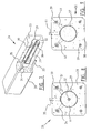
- Figure 1 shows a view of a mould 1 for preparing a pile according to the invention.
- a fixing element 2 is arranged in longitudinal direction for the purpose of fixing a fill element 4 (not shown).
- Mould 1 is further provided with longitudinal reinforcement 3 extending in lengthwise direction of mould 1. This longitudinal reinforcement 3 ensures that the chance of the pile breaking during transport and pile-driving is reduced.
- Figure 2 shows the mould of Figure 1, wherein a fill element 4, preferably of polystyrene foam, is arranged round fixing element 2.
- Fill element 4 is provided along the whole length with a slot 5. It is possible to slide fill element 4 over the fixing element through this slot 5.
- Slot 5 extends inward at least to a position beyond the centre of gravity 6 of the fill element.
- the fill element is rotated such that opening 8 of slot 5 is directed toward the upper side of mould 1.
- Figure 3 shows pouring of concrete 7 in mould 1.
- the pile is given the desired form by means of walls 9 and 10 and bottom 11 of the mould. Possible shapes are, among others, square, pentagonal, hexagonal, octagonal or round.
- the longitudinal reinforcement 3 and fill element 4 are wholly enclosed by the concrete 7 during the pouring.
- Fixing element 2 here ensures that fill element 4 does not displace to the top side of the mould, or only does so to a limited extent.
- Pouring of concrete 7 continues until the upper edge of walls 9 and 10 is reached. The whole is then allowed to cure for some time.
- the mould is optionally provided with a mould cover (not shown) extending along the top side of the mould.
- FIG. 4 shows a pile 12 according to the invention.
- Pile 12 is provided with a fill element 13 extending in longitudinal direction of the pile, wherein the fill element is enclosed by a casing 14 of cured concrete.
- Fill element 13 consists of a number of separate parts 13a and 13b, whereby the fill element can be arranged relatively easily during preparation of pile 12.
- the fixing element 15 is visible that has served to hold fill element 13 in its position. It is however possible to remove this fixing element 15 during or after curing of pile 12.
- Pile 12 is further provided with longitudinal reinforcement 16 in order to ensure a reduced chance of pile 12 breaking during transport and pile-driving.
- FIG. 5 shows a cross-section of pile 12 of Figure 4.
- the fill element 13 is enclosed by a concrete casing 14.
- Longitudinal reinforcement 16 is incorporated in this concrete casing.
- Fill element 13 is provided with a slot 17 extending up to the centre of gravity 18 of the fill element.
- Fill element 13 lies against fixing element 15.
- Fixing element 15 and fill element 13 are positioned during preparation of pile 12 such that fill element 13 is situated centrally in pile 12. Further indicated are optional spacers 19 remaining on the outer surface of fill element 13 which further contribute toward the fill element 13 being held at the desired position during preparation of pile 12.
- the use of only a fixing element 15 is however also possible.
- Figure 6 shows an embodiment of the invention wherein spacers 20 and 21 are used to position fill element 22 during preparation of pile 23.
- Spacers 20 are connected to longitudinal reinforcement 24 extending in lengthwise direction of pile 23.
- the spacer 21 was connected to a mould cover arranged on the top side of mould 25 (not shown).
- Spacers 20 can optionally be used separately or spacer(s) 21 can be used separately. It is however recommended to use them together.
- FIG. 7 shows another preferred embodiment of a pile 26 according to the invention.
- Pile 26 is provided with a fill element 27 situated in the core of pile 26.
- This fill element 27 is here enclosed by a concrete casing 28.
- This fill element 27 consists of a tube 29, preferably of plastic, which is provided at one end with a securing element 31 extending along inner wall 30 of the tube.
- This securing element 31 is preferably manufactured from metal or plastic.
- Securing element 31 herein lies close-fittingly against inner wall 30 of tube 29.
- Spacers 34 and/or 35 are optionally arranged in order to further ensure that tube 29 is held centrally in the pile 26 to be formed during preparation of the pile.
- Spacers 34 are attached to longitudinal reinforcement 33 of pile 26, spacer 35 having been connected to the mould and/or mould cover (not shown) during preparation of the pile. During preparation of pile 26 the tube 29 comes to lie against these spacers 34 and/or 35, whereby tube 29 can be positioned precisely.
- Figure 8 shows a cross-section of pile 26 of Figure 7.
- Tube 29 is situated centrally in pile 26.
- a securing element 31 is arranged in tube 29.
- This securing element 31 is arranged round fixing element 32.
- Tube 29 is enclosed by a casing 28 of cured concrete.
- Longitudinal reinforcement 33 is arranged in this casing 28 for additional strength during transport.
- Spacers 34 and/or 35 are further received in concrete casing 28. These spacers 34 and/or 35 are used during manufacture to position tube 29 centrally in pile 26.
- Figure 9 shows a pile 36 according to a further embodiment of the present invention.
- the fill element herein comprises a tube 37, preferably of plastic.
- Tube 37 is enclosed by a concrete casing 38.
- Longitudinal reinforcement 39 is received in this concrete casing 38.
- This longitudinal reinforcement 39 extends in the lengthwise direction of pile 36 and reduces the chance of pile 36 breaking during transport and pile-driving.
- Spacers 40 and 41 are further provided. These spacers 40 and/or 41 are used during manufacture of pile 36 to position tube 37 centrally in pile 36.
- Figure 10 shows a pile 42 according to the invention.
- This pile 42 is open on the top side such that fill element 43, which is situated centrally in pile 42, can be seen.
- This fill element 43 is enclosed by a concrete casing 44.
- the upper end and/or the lower end of the pile is provided with a reinforcing band 45 extending in peripheral direction of pile 42.
- FIG 11 shows a cross-section of pile 42 of Figure 10.
- Pile 42 herein comprises a fill element 43 extending along a fixing element 46.
- Fill element 43 is enclosed by a concrete casing 44 incorporating longitudinal reinforcement 47.
- the head of the pile is however open, at least fill element 43 is visible from outside.
- a reinforcing band 45 extending along the periphery of the pile is arranged in the head, close to the end of the pile.
- FIG 12 shows a recommended embodiment of the present invention.
- Pile 48 herein comprises a concrete closure 49 (not shown) which ensures that a solid head 50 and/or foot is formed.
- the pile is further provided with a concrete casing 51.
- FIG 13 shows pile 48 of Figure 12 in cross-section.
- Pile 48 is provided with a solid head 50 and a concrete casing 51 provided with longitudinal reinforcement 52.
- a fill element 53 also extends in longitudinal direction of pile 48.
- the concrete closure 54 is preferably integrated with the concrete casing 51 of pile 48. Owing to this solid head 50 pile 48 is better able to withstand the relatively great forces during pile-driving.
- Pile 48 is preferably further provided in head 50 and/or the foot with so-called spiral reinforcement 54. This spiral reinforcement 54 makes head 50 still better able to withstand the great forces during pile-driving.
- Figure 14 shows a long mould 55 wherein the mould is divided into a number of sub-moulds 56. Sub-moulds 56 are separated from each other by means of end surface partitions 57. A plurality of concrete piles can be prepared in a batch by making use of such a long mould 55. Longitudinal reinforcement 58 and fill elements 59 are arranged in sub-moulds 56. These fill elements are positioned using a fixing element 60 (not shown).
- Figure 15 shows a further preferred embodiment of the invention. This embodiment greatly resembles the embodiment shown in figure 5 and a detailed description thereof will not therefore be given.
- the embodiment of figure 15 shows a fill element with an octagonal cross-section which is enclosed by a concrete casing 64 which incorporates longitudinal reinforcement 66.
- Fill element 63 is provided with a slot 17 so that the fill element can be pushed over fixing element 15.
- spacers 69 do not rest on the outer surface of fill element 63 but are extended to a position against the central fixing element 15.
- Spacers 69 are herein arranged at the position of the intermediate spaces between the separate parts of fill element 63. Because spacers 69 rest on fixing element 15, less stringent structural requirements need be made of the material of fill element 63.
- the material of fill element 13 must after all have a strength such that the underside of the respective spacers 19 do not cause any damage to the outer surface of fill element 13.
- five spacers 69 are arranged in the embodiment shown in figure 15. In other embodiments (not shown) this number can however be smaller, as discussed above with reference to other embodiments of the invention.
- Figure 16 shows a further preferred embodiment which largely corresponds with the embodiment shown in figure 6.
- no fixing element 15 is arranged in fill element 73 of octagonal cross-section 9.
- fill element 73 is held in position by spacers 74 resting on one side on the outer surface 72 of fill element 73 and/or attached on the other side to longitudinal reinforcement 39.
- five spacers 74 are once again shown. An application with the small number of spacers does however fall wholly within the reach of the skilled person.
- FIG 17 shows a further preferred embodiment of the present invention.
- no fixing element is arranged in fill element 79.
- Fill element 79 is held in position in this embodiment by a spacer 75 extending in fill element 79, wherein spacer 75 is provided at the end extending in fill element 75 (preferably of recycled polystyrene foam) with a barbed profile 80 such that it is firmly connected to fill element 75.
- the other end 81 of spacer 75 supports against a so-called mould cover (not shown), such as for instance a pin which extends transversely of the longitudinal direction of the mould and which is connected to the top side of the longitudinal walls of the mould. This prevents fill element 79 floating upward during pouring of the concrete.
- spacers 77 can also be used which are attached to longitudinal reinforcement 76. An even better fixation of fill element 79 in the mould is thus obtained.
Abstract
Description
- The present invention relates to a method for manufacturing a pile; to a pile obtainable with this method and to a pile.
- In the prior art the use of piles to support buildings has been known for a long time. Piles that are currently used can be manufactured in per se efficient manner by pouring concrete into a mould, this mould giving the pile the desired form. The use of a mould provides advantages because it is a relatively simple manner of preparing piles. The drawback of this method of preparing piles is that only solid piles can be manufactured. These solid piles are relatively heavy and have to be provided with relatively heavy longitudinal reinforcement. This results in transport costs being relatively high.
- In addition, not all concrete present in the solid concrete pile is necessary from a structural viewpoint. In particular a portion of the concrete present around the core, i.e. the centre of the pile, could from a structural point of view be removed and replaced by another material, preferably a lighter and/or cheaper material.
- No practical method has however been available heretofore for the manufacture of such piles. This has the consequence that structurally too much material is used to prepare a pile, this having an unfavourable effect on the costs of producing and transporting the pile. It further results in a greater environmental impact.
- The present invention has for its object to provide a solution to the above stated problems.
- A first aspect of the present invention therefore relates to a method for preparing a pile, comprising the steps of:
- I) arranging in a mould a plastic fill element and at least one positioning means for positioning the plastic fill element in the mould;
- ii) pouring concrete into the mould such that the fill element is substantially enclosed by the concrete;
- iii) at least partially curing the poured concrete.
- An advantage of this method is that a pile with an acceptable structural strength can be manufactured wherein less concrete need be used than in a conventional solid pile. This has a favourable effect on the production cost of the pile and on the environmental impact resulting from the production process.
- It is possible to position the fill element at a desired position by means of the positioning means. The fill element is preferably positioned such that it is situated centrally in the pile to be formed.
- It is recommended that the fill element comprises a plastic foam material, such as for instance a polystyrene foam. An advantage of the use of such materials is that they are relatively light but can also withstand the pressure of the poured concrete. This prevents considerable differences occurring in the thickness of the wall of the pile along its length. The plastic foam is preferably in the form of an already solid foam which can be brought into a desired shape which it also substantially retains during pouring of the concrete.
- The positioning means preferably comprise a fixing element extending in longitudinal direction of the mould, wherein during the performing of step i) the fill element is arranged on or round the fixing element. Through the use of such a fixing element it is possible to arrange the fill element in the mould, preferably centrally in the pile to be formed, in simple and rapid manner. This has a favourable effect on, among other things, the production cost of the pile.
- It is further recommended that the positioning means comprises at least one spacer, wherein the fill element is positioned before or during performing of step ii) of the method according to the invention.
- An advantage of the use of such spacers is that the fill element can be positioned relatively quickly and easily at the correct location in the pile to be formed. The fill element can be positioned during pouring of the concrete due to the presence of the spacers, which are preferably of plastic. Through the pouring of the concrete the fill element will generally begin to float, at least move toward the top side of the mould. By arranging spacers in the mould this upward directed movement of the fill element is stopped, and the fill element is positioned. A plurality of spacers are preferably used to position the fill element. The spacers can be provided with a clamping part with which they can be fixed for instance to the reinforcement and/or mould of the pile.
- It is recommended that the spacer is fixed to the reinforcement of the pile to be formed. It is particularly recommended here that it is fixed to longitudinal reinforcement of the pile. It is further also possible for the spacers to be (removably) fixed to the mould or a mould cover extending over the top side of the mould. Such a mould cover preferably comprises a metal plate or pin.
- It is further recommended that the spacers are placed partially in the fill element. It is then recommended that the fill element comprises a plastic foam material, such as for instance recycled polystyrene or expanded polystyrene. The portion of the spacer extending into the fill element is then preferably provided with a barbed profile such that a good connection is obtained between the fill element and the spacer. The spacer is in this case preferably supported by a mould cover.
- It is further recommended that the positioning means substantially centre the fill element in the pile to be formed. A pile is hereby obtained which very readily absorbs the forces during inter alia pile-driving. In addition less concrete is necessary, this resulting in reduced production cost and less of an environmental impact.
- In a recommended embodiment the positioning means comprise a fixing element extending in longitudinal direction as well as spacers. A good fixation of the fill element in the mould is thus obtained.
- The fill element is preferably manufactured from material with a lower specific mass than cured concrete. An advantage hereof is that the pile is relatively light, which has a favourable effect on the cost of transporting the pile.
- It is recommended that the fill element extends substantially along the whole length of the mould. An advantage hereof is that even less concrete need be used. This has a favourable effect on production cost and on environmental impact.
- It is a further recommended that the fill element is of elongate form.
- It is also recommended that the fill element comprises separate parts. The advantage hereof is that people involved in the manufacture of the pile can relatively easily arrange the fill element, at least the separate parts thereof, on the fixing element (or spacers). In addition, the fill element is then relatively easy to transport. This is particularly recommended when the pile is relatively long.
- In a further preferred embodiment the fill element is constructed from a number of fill element parts placed successively with intermediate spacing. The intermediate spaces are herein filled with concrete during pouring. The structural stiffness of the pile can be adjusted as required by variation of the number, the positions and/or the dimensions of the intermediate spaces. In a further embodiment the spacers extend through the intermediate spaces so that the spacers can rest on the fixing element instead of on the fill element.
- It is possible by means of the fixing element to position the fill element in the mould such that the fill element is centred in the pile to be formed.
- The fixing element preferably comprises a soft steel rod, a prestressed steel wire, a prestressed steel strand or a prestressed plastic wire.
- The fill element is preferably arranged at a distance from a first outer end and/or a second outer end of the mould such that at least one solid end of the pile is formed when the concrete is poured. The advantage hereof is that a solid head and/or foot of the pile is obtained in this manner which can withstand relatively great loads during pile-driving. An additional advantage is that no earth can enter the pile during pile-driving.
- It is further recommended that the fill element is rod-like and is provided with a slot extending in the longitudinal direction for arranging the fill element on or round the fixing element. The fill element can be arranged very quickly by means of such a slot.
- It is also recommended that the slot width of the fill element is greater than the transverse dimension of the fixing element. The fill element can hereby be arranged quickly and easily on or round the fixing element, and can also be displaced.
- It is further recommended that the slot extends beyond the centre of gravity of the fill element.
- It is also recommended that the slot of the fill element is pushed over the fixing element such that the fill element is substantially centred in the pile to be formed, and wherein the fill element is rotated before or during pouring of the concrete such that the fill element is fixed on the fixing element during the pouring. Fixing is here understood to mean, among other things, that the fill element cannot float upward during the pouring.
- It is further recommended that longitudinal reinforcement is arranged in the mould prior to the performing of step ii) of the method according to the invention such that the longitudinal reinforcement is incorporated in the concrete. Such longitudinal reinforcement results in a reduced chance of the pile breaking during transport and pile-driving.
- In a recommended embodiment spiral reinforcement is arranged at least at one end of the mould. Through the arranging of such spiral reinforcement the end of the pile is better able to withstand the relatively great loads during pile-driving.
- It is also recommended that a reinforcing band extending along the inner periphery of the mould is arranged at least at one end of the mould. Such a reinforcing band is preferably of metal. An advantage of such a band is that it can be placed relatively easily in the mould. An additional advantage is that the band can also be arranged after curing of the pile. A further advantage of such a band is that a head or a foot is obtained which can withstand the relatively great loads during pile-driving.
- The fill element preferably comprises a tube. The advantage of such a fill element is that it is relatively strong, whereby a relatively large amount of concrete can be poured onto it without it being compressed. In addition, relatively little material is required to manufacture a fill element of a relatively large size.
- In a recommended embodiment the fill element is a tube, wherein at least a portion of the inner side of the tube is provided with a securing element extending over the inner periphery of the tube. It is recommended here that the securing element comprises a plastic foam material such as polystyrene foam. The securing element can then be arranged on or round the fixing element such that the tube is positioned. It is recommended here that the securing element is a plastic cylinder, the wall of which is in clamping contact with the inner wall of the tube.
- It is further recommended that the fixing element is removed after or during performing of step iii).
- In an embodiment according to the invention the concrete in step ii) comprises broken concrete granulate, this resulting in a relatively small environmental impact since broken concrete granulate can be reused.
- In another embodiment of the present method a metal band extending along the periphery of the pile is arranged after performing step iii). It is particularly recommended here that the pile is substantially cured.
- A second aspect of the present invention relates to a pile obtainable with the above described method.
- A third aspect of the present invention relates to a pile comprising a casing of cured concrete and a core extending in longitudinal direction of the pile, which core comprises a plastic fill element.
- The advantage of such a pile is that it comprises relatively little concrete. The cost price of such a pile is hereby relatively low. Such a pile further has less of an environmental impact since it comprises less concrete than a solid pile.
- It is recommended here that the fill element comprises a plastic foam material such as polystyrene foam. Such material is relatively light and well able to withstand compression, whereby a pile is obtained with a diameter of the core which is substantially the same everywhere.
- It is recommended that the fill element has a substantially round, polygonal such as octagonal or rectangular form.
- It is further recommended that the fill element is rod-like.
- In a recommended embodiment the fill element is provided with a slot which extends in longitudinal direction of the fill element and which is used to arrange the fill element on the fixing element. The slot preferably extends as far as or beyond the centre of gravity of the fill element. If the fixing element is removed after preparation of the pile, this slot can be used for different purposes, such as for instance concrete core activating purposes. Particularly when a plastic foam material is used, the core can then serve as insulating/protective material for a conduit arranged through the slot.
- It is recommended here that the slot width is smaller than the transverse dimension of the fixing element. The advantage hereof is that the fill element can be arranged relatively easily on the fixing element and, if necessary, can be rotated more easily. Close to the end of the slot the slot width is preferably greater than the transverse dimension of the fixing element. The fill element can hereby be arranged even more easily on the fixing element and held at the desired position.
- It is recommended that at least one end of the pile is provided with a concrete closure. The advantage of such a closure is that a head and/or foot of the pile is obtained which can withstand relatively great loads during pile-driving. An additional advantage is that no earth can penetrate into the pile during pile-driving.
- It is also recommended that the core is provided with a fixing element extending in longitudinal direction of the pile. The advantage of such a fixing element is that it can also be used as prestressed reinforcement for purposes of strength, but also as earthing rod/earthing wire, for instance for an electrical system.
- Mentioned and other features of the method for manufacturing a pile and the pile according to the invention will be further elucidated hereinbelow on the basis of a number of exemplary embodiments, which are given only by way of example without the invention thereby being deemed limited thereto. Reference is herein made to the accompanying drawings, in which:
- Figure 1 shows a view of a mould for preparing a pile according to the invention;
- Figure 2 shows a view of the mould of Figure 1, wherein a fill element is arranged for the preparation of a pile according to the invention;
- Figure 3 shows a view of the pouring of concrete into the mould of Figure 2;
- Figure 4 shows a view of a pile according to the invention;
- Figure 5 shows a cross-section along the line IV-IV of the pile of Figure 4;
- Figure 6 shows a cross-section of a pile according to an embodiment of the invention;
- Figure 7 shows a view of a pile according to the invention;
- Figure 8 shows a cross-section along the line VIII-VIII of the pile of Figure 7;
- Figure 9 shows a cross-section of a further embodiment of the pile;
- Figure 10 shows a view of a pile according to an embodiment of the invention;
- Figure 11 shows a cross-section of the pile of Figure 10;
- Figure 12 shows a view of a pile according to an embodiment of the invention;
- Figure 13 shows a cross-section of the pile of Figure 12;
- Figure 14 shows a top view of a mould for preparing a pile according to the invention;
- Figure 15 shows a cross-section of a further preferred embodiment of a pile according to the invention;
- Figure 16 shows yet another embodiment of the pile according to the invention;
- Figure 17 shows yet another embodiment of the pile according to the invention.
- Figure 1 shows a view of a
mould 1 for preparing a pile according to the invention. On the inner side of mould 1 a fixingelement 2 is arranged in longitudinal direction for the purpose of fixing a fill element 4 (not shown).Mould 1 is further provided withlongitudinal reinforcement 3 extending in lengthwise direction ofmould 1. Thislongitudinal reinforcement 3 ensures that the chance of the pile breaking during transport and pile-driving is reduced. - Figure 2 shows the mould of Figure 1, wherein a
fill element 4, preferably of polystyrene foam, is arranged round fixingelement 2. Fillelement 4 is provided along the whole length with aslot 5. It is possible to slidefill element 4 over the fixing element through thisslot 5.Slot 5 extends inward at least to a position beyond the centre ofgravity 6 of the fill element. In order to ensure thatfill element 4 does not detach from fixingelement 2 during pouring of the concrete 7 (not shown), the fill element is rotated such thatopening 8 ofslot 5 is directed toward the upper side ofmould 1. - Figure 3 shows pouring of
concrete 7 inmould 1. The pile is given the desired form by means ofwalls 9 and 10 and bottom 11 of the mould. Possible shapes are, among others, square, pentagonal, hexagonal, octagonal or round. Thelongitudinal reinforcement 3 and fillelement 4 are wholly enclosed by theconcrete 7 during the pouring. Fixingelement 2 here ensures thatfill element 4 does not displace to the top side of the mould, or only does so to a limited extent. Pouring ofconcrete 7 continues until the upper edge ofwalls 9 and 10 is reached. The whole is then allowed to cure for some time. The mould is optionally provided with a mould cover (not shown) extending along the top side of the mould. - Figure 4 shows a
pile 12 according to the invention.Pile 12 is provided with afill element 13 extending in longitudinal direction of the pile, wherein the fill element is enclosed by acasing 14 of cured concrete. Fillelement 13 consists of a number ofseparate parts 13a and 13b, whereby the fill element can be arranged relatively easily during preparation ofpile 12. The fixingelement 15 is visible that has served to holdfill element 13 in its position. It is however possible to remove this fixingelement 15 during or after curing ofpile 12.Pile 12 is further provided withlongitudinal reinforcement 16 in order to ensure a reduced chance ofpile 12 breaking during transport and pile-driving. - Figure 5 shows a cross-section of
pile 12 of Figure 4. Here thefill element 13 is enclosed by aconcrete casing 14.Longitudinal reinforcement 16 is incorporated in this concrete casing. Fillelement 13 is provided with aslot 17 extending up to the centre ofgravity 18 of the fill element. Fillelement 13 lies against fixingelement 15. Fixingelement 15 and fillelement 13 are positioned during preparation ofpile 12 such that fillelement 13 is situated centrally inpile 12. Further indicated areoptional spacers 19 remaining on the outer surface offill element 13 which further contribute toward thefill element 13 being held at the desired position during preparation ofpile 12. The use of only a fixingelement 15 is however also possible. - Figure 6 shows an embodiment of the invention wherein
spacers element 22 during preparation ofpile 23.Spacers 20 are connected tolongitudinal reinforcement 24 extending in lengthwise direction ofpile 23. During manufacture ofpile 23 thespacer 21 was connected to a mould cover arranged on the top side of mould 25 (not shown).Spacers 20 can optionally be used separately or spacer(s) 21 can be used separately. It is however recommended to use them together. - Figure 7 shows another preferred embodiment of a
pile 26 according to the invention.Pile 26 is provided with afill element 27 situated in the core ofpile 26. Thisfill element 27 is here enclosed by aconcrete casing 28. Thisfill element 27 consists of atube 29, preferably of plastic, which is provided at one end with a securingelement 31 extending alonginner wall 30 of the tube. This securingelement 31 is preferably manufactured from metal or plastic. Securingelement 31 herein lies close-fittingly againstinner wall 30 oftube 29. By making use of such an arrangement it is possible to positiontube 29 centrally inpile 26 because the tube is arranged around fixingelement 32.Pile 26 is further provided withlongitudinal reinforcement 33 extending in theconcrete casing 28.Spacers 34 and/or 35 are optionally arranged in order to further ensure thattube 29 is held centrally in thepile 26 to be formed during preparation of the pile.Spacers 34 are attached tolongitudinal reinforcement 33 ofpile 26,spacer 35 having been connected to the mould and/or mould cover (not shown) during preparation of the pile. During preparation ofpile 26 thetube 29 comes to lie against thesespacers 34 and/or 35, wherebytube 29 can be positioned precisely. - Figure 8 shows a cross-section of
pile 26 of Figure 7.Tube 29 is situated centrally inpile 26. In order to holdtube 29 in position during manufacture a securingelement 31 is arranged intube 29. This securingelement 31 is arranged round fixingelement 32.Tube 29 is enclosed by acasing 28 of cured concrete.Longitudinal reinforcement 33 is arranged in thiscasing 28 for additional strength during transport.Spacers 34 and/or 35 are further received inconcrete casing 28. Thesespacers 34 and/or 35 are used during manufacture to positiontube 29 centrally inpile 26. - Figure 9 shows a pile 36 according to a further embodiment of the present invention. The fill element herein comprises a
tube 37, preferably of plastic.Tube 37 is enclosed by aconcrete casing 38.Longitudinal reinforcement 39 is received in thisconcrete casing 38. Thislongitudinal reinforcement 39 extends in the lengthwise direction of pile 36 and reduces the chance of pile 36 breaking during transport and pile-driving.Spacers spacers 40 and/or 41 are used during manufacture of pile 36 to positiontube 37 centrally in pile 36. - Figure 10 shows a
pile 42 according to the invention. Thispile 42 is open on the top side such that fillelement 43, which is situated centrally inpile 42, can be seen. Thisfill element 43 is enclosed by aconcrete casing 44. In order to impart extra strength to the head and/or the foot of the pile, the upper end and/or the lower end of the pile is provided with a reinforcingband 45 extending in peripheral direction ofpile 42. - Figure 11 shows a cross-section of
pile 42 of Figure 10.Pile 42 herein comprises afill element 43 extending along a fixingelement 46. Fillelement 43 is enclosed by aconcrete casing 44 incorporatinglongitudinal reinforcement 47. The head of the pile is however open, at least fillelement 43 is visible from outside. A reinforcingband 45 extending along the periphery of the pile is arranged in the head, close to the end of the pile. - Figure 12 shows a recommended embodiment of the present invention.
Pile 48 herein comprises a concrete closure 49 (not shown) which ensures that asolid head 50 and/or foot is formed. The pile is further provided with aconcrete casing 51. - Figure 13 shows pile 48 of Figure 12 in cross-section.
Pile 48 is provided with asolid head 50 and aconcrete casing 51 provided withlongitudinal reinforcement 52. Afill element 53 also extends in longitudinal direction ofpile 48. Theconcrete closure 54 is preferably integrated with theconcrete casing 51 ofpile 48. Owing to thissolid head 50pile 48 is better able to withstand the relatively great forces during pile-driving.Pile 48 is preferably further provided inhead 50 and/or the foot with so-calledspiral reinforcement 54. Thisspiral reinforcement 54 makeshead 50 still better able to withstand the great forces during pile-driving. - Figure 14 shows a
long mould 55 wherein the mould is divided into a number of sub-moulds 56. Sub-moulds 56 are separated from each other by means of end surface partitions 57. A plurality of concrete piles can be prepared in a batch by making use of such along mould 55.Longitudinal reinforcement 58 and fillelements 59 are arranged insub-moulds 56. These fill elements are positioned using a fixing element 60 (not shown). - Figure 15 shows a further preferred embodiment of the invention. This embodiment greatly resembles the embodiment shown in figure 5 and a detailed description thereof will not therefore be given. The embodiment of figure 15 shows a fill element with an octagonal cross-section which is enclosed by a
concrete casing 64 which incorporateslongitudinal reinforcement 66. Fillelement 63 is provided with aslot 17 so that the fill element can be pushed over fixingelement 15. In contrast to the embodiment shown in figure 5,spacers 69 do not rest on the outer surface offill element 63 but are extended to a position against thecentral fixing element 15.Spacers 69 are herein arranged at the position of the intermediate spaces between the separate parts offill element 63. Becausespacers 69 rest on fixingelement 15, less stringent structural requirements need be made of the material offill element 63. In the embodiment shown in figure 5 the material offill element 13 must after all have a strength such that the underside of therespective spacers 19 do not cause any damage to the outer surface offill element 13. In addition, fivespacers 69 are arranged in the embodiment shown in figure 15. In other embodiments (not shown) this number can however be smaller, as discussed above with reference to other embodiments of the invention. - Figure 16 shows a further preferred embodiment which largely corresponds with the embodiment shown in figure 6. In the further embodiment no fixing
element 15 is arranged infill element 73 of octagonal cross-section 9. In this embodiment fillelement 73 is held in position by spacers 74 resting on one side on theouter surface 72 offill element 73 and/or attached on the other side tolongitudinal reinforcement 39. In this embodiment fivespacers 74 are once again shown. An application with the small number of spacers does however fall wholly within the reach of the skilled person. - Figure 17 shows a further preferred embodiment of the present invention. In this embodiment no fixing element is arranged in fill element 79. Fill element 79 is held in position in this embodiment by a
spacer 75 extending in fill element 79, whereinspacer 75 is provided at the end extending in fill element 75 (preferably of recycled polystyrene foam) with abarbed profile 80 such that it is firmly connected to fillelement 75. Theother end 81 ofspacer 75 supports against a so-called mould cover (not shown), such as for instance a pin which extends transversely of the longitudinal direction of the mould and which is connected to the top side of the longitudinal walls of the mould. This prevents fill element 79 floating upward during pouring of the concrete. In addition, spacers 77 can also be used which are attached tolongitudinal reinforcement 76. An even better fixation of fill element 79 in the mould is thus obtained. - The present invention is not limited to the preferred embodiments thereof described herein. The rights sought are rather defined by the following claims, within the scope of which many modifications can be envisaged.
Claims (52)
- Method for preparing a pile, the method comprising the steps of:I) arranging in a mould a plastic fill element and at least one positioning means for positioning the plastic fill element in the mould;ii) pouring concrete into the mould such that the fill element is substantially enclosed by the concrete;iii) at least partially curing the poured concrete.
- Method as claimed in claim 1, wherein the fill element comprises a plastic foam material, preferably a polystyrene foam.
- Method as claimed in claim 1 or 2, wherein the positioning means comprise a fixing element extending in longitudinal direction of the mould, and wherein during performing of step i) the fill element is arranged on or round the fixing element.
- Method as claimed in claim 3, wherein the fixing element extends substantially centrally in the pile to be formed.
- Method as claimed in any of the claims 1-4, wherein the positioning means comprises at least one spacer, wherein the fill element is positioned before or during performing of step ii).
- Method as claimed in claim 5, wherein a first end of the spacer is arranged in the fill element and wherein a second end is supported against a mould cover.
- Method as claimed in any of the claims 1-6, wherein the positioning means comprises at least a first and second positioning means, and wherein the first positioning means comprises a fixing element extending in longitudinal direction of the mould, and wherein the second positioning means comprises at least one spacer.
- Method as claimed in any of the claims 1-7, wherein the spacer is fixed to reinforcement of the pile to be formed.
- Method as claimed in any of the claims 1-8, wherein the spacer is fixed to the mould cover and/or wall of the mould.
- Method as claimed in any of the claims 1-9, wherein the positioning means substantially centre the fill element in the pile to be formed.
- Method as claimed in any of the claims 1-10, wherein the fill element has a lower specific mass than cured concrete.
- Method as claimed in any of the claims 1-11, wherein the fill element extends substantially along the whole length of the mould.
- Method as claimed in any of the claims 1-12, wherein the fill element defines an elongate form.
- Method as claimed in any of the claims 1-13, wherein the fill element comprises separate parts.
- Method as claimed in claim 14, wherein the fill element is constructed from a number of fill element parts placed successively with intermediate spacing.
- Method as claimed in any of the claims 1-15, wherein the fill element is arranged at a distance from a first outer end and/or a second outer end of the mould such that at least one solid end of the pile is formed when the concrete is poured.
- Method as claimed in any of the claims 1-16, wherein the fill element is rod-like and is provided with a slot extending in the longitudinal direction for arranging the fill element on the fixing element.
- Method as claimed in claim 17, wherein the slot width is greater than the transverse dimension of the fixing element.
- Method as claimed in claim 17 or 18, wherein the slot extends beyond the centre of gravity of the fill element.
- Method as claimed in any of the claims 17-19, wherein the slot of the fill element is pushed over the fixing element such that the fill element is substantially centred in the pile to be formed, and wherein the fill element is rotated before or during pouring of the concrete such that the fill element is fixed on the fixing element during the pouring.
- Method as claimed in any of the claims 1-20, wherein longitudinal reinforcement is arranged in the mould prior to performing of step ii).
- Method as claimed in any of the claims 1-21, wherein spiral reinforcement is arranged at least at one end of the mould.
- Method as claimed in any of the claims 1-22, wherein a reinforcing band extending along the inner periphery of the mould is arranged at least at one end of the mould.
- Method as claimed in any of the claims 1-23, wherein the fixing element comprises a soft steel rod, a prestressed steel wire, a prestressed steel strand or a prestressed plastic wire.
- Method as claimed in any of the claims 1-24, wherein the fill element comprises a tube.
- Method as claimed in any of the claims 1-25, wherein the fill element is a tube, and wherein at least a portion of the inner side of the tube is provided with a securing element.
- Method as claimed in claim 26, wherein the securing element comprises a cylinder of plastic foam material, wherein substantially the whole wall of the cylinder is in clamping contact with the inner wall of the tube, whereby the cylinder is fixed in the tube.
- Method as claimed in any of the claims 1-27, wherein the fixing element is removed from the pile after or during performing of step iii).
- Method as claimed in any of the claims 1-28, wherein the concrete in step ii) comprises broken concrete granulate.
- Method as claimed in any of the claims 1-29, wherein a metal band extending along the periphery of the pile is arranged after performing step iii).
- Pile comprising a casing of cured concrete and a core extending in longitudinal direction of the pile, which core comprises a plastic fill element.
- Pile as claimed in claim 31, wherein the fill element comprises a plastic foam material, preferably a polystyrene foam, such as recycled polystyrene foam.
- Pile as claimed in claim 31 or 32, wherein the fill element has a substantially circular or polygonal cross-section.
- Pile as claimed in any of the claims 31-33, wherein the fill element is rod-like and provided with a slot extending in longitudinal direction for arranging the fill element on the fixing element.
- Pile as claimed in claim 34, wherein the slot width is greater than the transverse dimension of the fixing element.
- Pile as claimed in claim 34 or 35, wherein the slot extends beyond the centre of gravity of the fill element.
- Pile as claimed in any of the claims 30-36, wherein the fill element has a lower specific mass than cured concrete.
- Pile as claimed in any of the claims 30-37, wherein the fill element comprises a tube.
- Pile as claimed in any of the claims 30-38, wherein the fill element is a tube, wherein at least a portion of the inner side of the tube is provided with a securing element.
- Pile as claimed in claim 39, wherein the securing element comprises a cylinder of plastic foam material, wherein substantially the whole wall of the cylinder is in clamping contact with the inner wall of the tube, whereby the cylinder is fixed in the tube.
- Pile as claimed in any of the claims 31-40, wherein the fill element extends substantially along the whole length of the pile.
- Pile as claimed in any of the claims 31-41, wherein the fill element defines an elongate form.
- Pile as claimed in any of the claims 31-42, wherein the fill element is centred in the pile.
- Pile as claimed in any of the claims 31-43, wherein the fill element comprises separate parts.
- Pile as claimed in any of the claims 31-44, wherein the fill element is constructed from fill element parts placed successively with intermediate spacing.
- Pile as claimed in any of the claims 31-45, wherein at least one end of the pile is provided with a concrete closure.
- Pile as claimed in any of the claims 31-46, wherein the concrete casing is provided with longitudinal reinforcement.
- Pile as claimed in any of the claims 31-47, wherein at least one end of the concrete casing is provided with spiral reinforcement.
- Pile as claimed in any of the claims 31-48, wherein a reinforcing band extending along the inner periphery of the mould is arranged at least at one end of the mould.
- Pile as claimed in any of the claims 31-49, wherein the core is provided with a fixing element extending in longitudinal direction of the pile.
- Pile as claimed in any of the claims 31-50, wherein the fixing element comprises a soft steel rod, a prestressed steel wire or a prestressed plastic wire.
- Pile obtainable according to the method of any of the claims 1-30.
Applications Claiming Priority (2)
| Application Number | Priority Date | Filing Date | Title |
|---|---|---|---|
| NL1029468A NL1029468C2 (en) | 2005-07-08 | 2005-07-08 | Method for preparing pile for building, involves pouring concrete into mold arranged with polystyrene foam such that foam is enclosed by concrete, and curing concrete, partially |
| NL1030631A NL1030631C2 (en) | 2005-07-08 | 2005-12-09 | Method for manufacturing a pile with filling elements (plus pile). |
Publications (2)
| Publication Number | Publication Date |
|---|---|
| EP1741838A2 true EP1741838A2 (en) | 2007-01-10 |
| EP1741838A3 EP1741838A3 (en) | 2015-04-01 |
Family
ID=37137553
Family Applications (1)
| Application Number | Title | Priority Date | Filing Date |
|---|---|---|---|
| EP06076388.5A Withdrawn EP1741838A3 (en) | 2005-07-08 | 2006-07-10 | Method for preparing a pile provided with fill-elements and pile |
Country Status (2)
| Country | Link |
|---|---|
| EP (1) | EP1741838A3 (en) |
| NL (2) | NL1029468C2 (en) |
Cited By (5)
| Publication number | Priority date | Publication date | Assignee | Title |
|---|---|---|---|---|
| NL2001264C2 (en) * | 2008-02-07 | 2009-08-10 | Hanenberg Wegenbouw B V | Band element for applying boundaries in a pavement. |
| ITPD20080329A1 (en) * | 2008-11-12 | 2010-05-13 | Lucio Pedrocco | PALANCOLA IN PRECOMPRESSED REINFORCED CONCRETE, METHOD OF PRODUCTION OF SUCH A PALANCOLA AND WALL INCLUDING A PLURALITY OF SUCH PALANCOLE |
| FR3033514A1 (en) * | 2015-03-12 | 2016-09-16 | Conseil Service Investissements | PROCESS FOR MOLDING TUBULAR ELEMENTS IN MATERIAL COMPRISING CEMENT AND PIEU THUS OBTAINED |
| NL2019619A (en) * | 2016-09-22 | 2018-03-27 | Oskar Peter Henriette Pudelko | FOUNDATION METHOD, FOUNDATION COLUMN AND VIBRATION ABSORPTION BODY |
| NL2019370B1 (en) * | 2017-07-28 | 2019-02-19 | Berton Holding B V | Method for manufacturing an elongated fence post |
Families Citing this family (1)
| Publication number | Priority date | Publication date | Assignee | Title |
|---|---|---|---|---|
| NL2002150C (en) * | 2008-10-29 | 2010-05-03 | Univ Eindhoven Tech | SHAPING MODULE AND METHOD FOR MANUFACTURING A FOUNDATION. |
Citations (9)
| Publication number | Priority date | Publication date | Assignee | Title |
|---|---|---|---|---|
| GB357043A (en) * | 1931-01-16 | 1931-09-17 | Samuel Williams And Sons Ltd | Improvements in concrete piles |
| GB537736A (en) * | 1939-12-27 | 1941-07-04 | Prenton Brick And Tile Company | Improvements in and relating to hollow mouldable articles |
| US2274082A (en) * | 1939-08-31 | 1942-02-24 | Standard Oil Dev Co | Method for construction of marine foundations |
| FR875253A (en) * | 1941-08-14 | 1942-09-14 | Elin Ag Fu R Elek Sche Ind | Process for the constitution of hollow reinforced concrete pillars, concreted in vertical position, in particular for overhead power lines |
| GB715563A (en) * | 1952-06-23 | 1954-09-15 | Ferdinand William Berry | Improvements in spacer members for the reinforcement of reinforced concrete |
| AU499615B2 (en) * | 1977-02-11 | 1979-04-26 | Nippon Concrete Kogyo K.K. | Concrete pile orthe like structure |
| US4178338A (en) * | 1977-02-07 | 1979-12-11 | A-Betong Ab | Method of casting thin-walled, hollow concrete posts |
| JPH0321718A (en) * | 1989-06-17 | 1991-01-30 | Chugoku Concrete Kogyo Kk | Foundation pile for weak ground |
| US5608991A (en) * | 1993-05-18 | 1997-03-11 | Yamashita; Senji | Flexible form member and method of forming through hole by means of the form member |
-
2005
- 2005-07-08 NL NL1029468A patent/NL1029468C2/en not_active IP Right Cessation
- 2005-12-09 NL NL1030631A patent/NL1030631C2/en active Search and Examination
-
2006
- 2006-07-10 EP EP06076388.5A patent/EP1741838A3/en not_active Withdrawn
Patent Citations (9)
| Publication number | Priority date | Publication date | Assignee | Title |
|---|---|---|---|---|
| GB357043A (en) * | 1931-01-16 | 1931-09-17 | Samuel Williams And Sons Ltd | Improvements in concrete piles |
| US2274082A (en) * | 1939-08-31 | 1942-02-24 | Standard Oil Dev Co | Method for construction of marine foundations |
| GB537736A (en) * | 1939-12-27 | 1941-07-04 | Prenton Brick And Tile Company | Improvements in and relating to hollow mouldable articles |
| FR875253A (en) * | 1941-08-14 | 1942-09-14 | Elin Ag Fu R Elek Sche Ind | Process for the constitution of hollow reinforced concrete pillars, concreted in vertical position, in particular for overhead power lines |
| GB715563A (en) * | 1952-06-23 | 1954-09-15 | Ferdinand William Berry | Improvements in spacer members for the reinforcement of reinforced concrete |
| US4178338A (en) * | 1977-02-07 | 1979-12-11 | A-Betong Ab | Method of casting thin-walled, hollow concrete posts |
| AU499615B2 (en) * | 1977-02-11 | 1979-04-26 | Nippon Concrete Kogyo K.K. | Concrete pile orthe like structure |
| JPH0321718A (en) * | 1989-06-17 | 1991-01-30 | Chugoku Concrete Kogyo Kk | Foundation pile for weak ground |
| US5608991A (en) * | 1993-05-18 | 1997-03-11 | Yamashita; Senji | Flexible form member and method of forming through hole by means of the form member |
Cited By (7)
| Publication number | Priority date | Publication date | Assignee | Title |
|---|---|---|---|---|
| NL2001264C2 (en) * | 2008-02-07 | 2009-08-10 | Hanenberg Wegenbouw B V | Band element for applying boundaries in a pavement. |
| EP2088241A1 (en) * | 2008-02-07 | 2009-08-12 | Hanenberg Wegenbouw B.V. | Curb element for providing boundaries in a pavement |
| ITPD20080329A1 (en) * | 2008-11-12 | 2010-05-13 | Lucio Pedrocco | PALANCOLA IN PRECOMPRESSED REINFORCED CONCRETE, METHOD OF PRODUCTION OF SUCH A PALANCOLA AND WALL INCLUDING A PLURALITY OF SUCH PALANCOLE |
| FR3033514A1 (en) * | 2015-03-12 | 2016-09-16 | Conseil Service Investissements | PROCESS FOR MOLDING TUBULAR ELEMENTS IN MATERIAL COMPRISING CEMENT AND PIEU THUS OBTAINED |
| NL2019619A (en) * | 2016-09-22 | 2018-03-27 | Oskar Peter Henriette Pudelko | FOUNDATION METHOD, FOUNDATION COLUMN AND VIBRATION ABSORPTION BODY |
| WO2018084697A1 (en) * | 2016-09-22 | 2018-05-11 | Pudelko Oskar Peter Henriette | Foundation method, foundation column part, and vibration absorption member |
| NL2019370B1 (en) * | 2017-07-28 | 2019-02-19 | Berton Holding B V | Method for manufacturing an elongated fence post |
Also Published As
| Publication number | Publication date |
|---|---|
| NL1030631C2 (en) | 2007-01-09 |
| EP1741838A3 (en) | 2015-04-01 |
| NL1029468C2 (en) | 2007-01-09 |
Similar Documents
| Publication | Publication Date | Title |
|---|---|---|
| EP1741838A2 (en) | Method for preparing a pile provided with fill-elements and pile | |
| CN108457421B (en) | Manufacturing die and manufacturing method of assembled reinforced concrete U-shaped frame beam | |
| KR101349297B1 (en) | Concrete Strengthening Steel Tube Pile and Manufacturing Method thereof | |
| EP3272481A1 (en) | A method for manufacturing prestressed concrete posts and a prestressed concrete post | |
| JP4253298B2 (en) | Building elements and methods of manufacturing | |
| KR102120647B1 (en) | Composite blocks of stone and concrete and manufacturing method thereof | |
| CN107217790B (en) | Prefabricated reinforced concrete frame hollow column and construction method thereof | |
| CN107735535B (en) | Stackable wall spacer for supporting reinforcement in concrete construction | |
| EP3006639B1 (en) | Module for slabs and metho to make said module | |
| CN210791468U (en) | Concrete prefabricated part demoulding equipment | |
| CN213448425U (en) | Rivet precast pile with groove | |
| CN210238488U (en) | Concrete pile body structure | |
| KR100929861B1 (en) | Method for constructing a reinforcement structure for a perforated slope using a crank shaped anchor | |
| CN209686711U (en) | Prefabricated laminated superposed column, reinforced column and assembled architecture body | |
| EP3059350A1 (en) | Formwork edge element and method for forming a foundation for a building | |
| CN111590714A (en) | Precast concrete pile tip and preparation method thereof | |
| JP5562660B2 (en) | Prestressed concrete structure | |
| CN101684676A (en) | Perlite polyphenylene compound filling block, method for preparing same and filled floor plate construction method | |
| CN205889491U (en) | Pouring mold of board -like concrete reinforcement locating piece | |
| CN218149783U (en) | Exempt from construction structures in formwork equipment foundation reservation bolt hole | |
| CN109057159A (en) | Prefabricated laminated superposed column, assembled architecture body and assembled architecture body method of construction | |
| EP0841435A1 (en) | Sound-absorbing elements | |
| CN220667147U (en) | Thin-wall high-rigidity cement pole | |
| JP5902048B2 (en) | How to build a ground tank | |
| KR102546462B1 (en) | Hollow Core Body Structure using Spacer |
Legal Events
| Date | Code | Title | Description |
|---|---|---|---|
| PUAI | Public reference made under article 153(3) epc to a published international application that has entered the european phase |
Free format text: ORIGINAL CODE: 0009012 |
|
| AK | Designated contracting states |
Kind code of ref document: A2 Designated state(s): AT BE BG CH CY CZ DE DK EE ES FI FR GB GR HU IE IS IT LI LT LU LV MC NL PL PT RO SE SI SK TR |
|
| AX | Request for extension of the european patent |
Extension state: AL BA HR MK YU |
|
| PUAL | Search report despatched |
Free format text: ORIGINAL CODE: 0009013 |
|
| AK | Designated contracting states |
Kind code of ref document: A3 Designated state(s): AT BE BG CH CY CZ DE DK EE ES FI FR GB GR HU IE IS IT LI LT LU LV MC NL PL PT RO SE SI SK TR |
|
| AX | Request for extension of the european patent |
Extension state: AL BA HR MK RS |
|
| RIC1 | Information provided on ipc code assigned before grant |
Ipc: B28B 23/18 20060101ALI20150220BHEP Ipc: E02D 5/30 20060101AFI20150220BHEP Ipc: E02D 5/10 20060101ALI20150220BHEP Ipc: E02D 5/52 20060101ALI20150220BHEP Ipc: B28B 23/00 20060101ALI20150220BHEP Ipc: E04C 3/34 20060101ALN20150220BHEP Ipc: B28B 23/14 20060101ALI20150220BHEP |
|
| RAP1 | Party data changed (applicant data changed or rights of an application transferred) |
Owner name: BETONSON PREFAB B.V. |
|
| AKY | No designation fees paid | ||
| AXX | Extension fees paid |
Extension state: MK Extension state: HR Extension state: BA Extension state: AL Extension state: RS |
|
| REG | Reference to a national code |
Ref country code: DE Ref legal event code: R108 |
|
| STAA | Information on the status of an ep patent application or granted ep patent |
Free format text: STATUS: THE APPLICATION IS DEEMED TO BE WITHDRAWN |
|
| 18D | Application deemed to be withdrawn |
Effective date: 20151002 |