EP1741592B1 - Shift lever device - Google Patents
Shift lever device Download PDFInfo
- Publication number
- EP1741592B1 EP1741592B1 EP05727543A EP05727543A EP1741592B1 EP 1741592 B1 EP1741592 B1 EP 1741592B1 EP 05727543 A EP05727543 A EP 05727543A EP 05727543 A EP05727543 A EP 05727543A EP 1741592 B1 EP1741592 B1 EP 1741592B1
- Authority
- EP
- European Patent Office
- Prior art keywords
- shift lever
- housing
- housing member
- lever
- predetermined direction
- Prior art date
- Legal status (The legal status is an assumption and is not a legal conclusion. Google has not performed a legal analysis and makes no representation as to the accuracy of the status listed.)
- Ceased
Links
Images


Classifications
-
- F—MECHANICAL ENGINEERING; LIGHTING; HEATING; WEAPONS; BLASTING
- F16—ENGINEERING ELEMENTS AND UNITS; GENERAL MEASURES FOR PRODUCING AND MAINTAINING EFFECTIVE FUNCTIONING OF MACHINES OR INSTALLATIONS; THERMAL INSULATION IN GENERAL
- F16H—GEARING
- F16H59/00—Control inputs to control units of change-speed- or reversing-gearings for conveying rotary motion
- F16H59/02—Selector apparatus
- F16H59/0204—Selector apparatus for automatic transmissions with means for range selection and manual shifting, e.g. range selector with tiptronic
-
- F—MECHANICAL ENGINEERING; LIGHTING; HEATING; WEAPONS; BLASTING
- F16—ENGINEERING ELEMENTS AND UNITS; GENERAL MEASURES FOR PRODUCING AND MAINTAINING EFFECTIVE FUNCTIONING OF MACHINES OR INSTALLATIONS; THERMAL INSULATION IN GENERAL
- F16H—GEARING
- F16H59/00—Control inputs to control units of change-speed- or reversing-gearings for conveying rotary motion
- F16H59/02—Selector apparatus
- F16H2059/026—Details or special features of the selector casing or lever support
- F16H2059/0273—Cardan or gimbal type joints for supporting the lever
-
- Y—GENERAL TAGGING OF NEW TECHNOLOGICAL DEVELOPMENTS; GENERAL TAGGING OF CROSS-SECTIONAL TECHNOLOGIES SPANNING OVER SEVERAL SECTIONS OF THE IPC; TECHNICAL SUBJECTS COVERED BY FORMER USPC CROSS-REFERENCE ART COLLECTIONS [XRACs] AND DIGESTS
- Y10—TECHNICAL SUBJECTS COVERED BY FORMER USPC
- Y10T—TECHNICAL SUBJECTS COVERED BY FORMER US CLASSIFICATION
- Y10T74/00—Machine element or mechanism
- Y10T74/20—Control lever and linkage systems
- Y10T74/20012—Multiple controlled elements
- Y10T74/20018—Transmission control
- Y10T74/2014—Manually operated selector [e.g., remotely controlled device, lever, push button, rotary dial, etc.]
- Y10T74/20159—Control lever movable through plural planes
-
- Y—GENERAL TAGGING OF NEW TECHNOLOGICAL DEVELOPMENTS; GENERAL TAGGING OF CROSS-SECTIONAL TECHNOLOGIES SPANNING OVER SEVERAL SECTIONS OF THE IPC; TECHNICAL SUBJECTS COVERED BY FORMER USPC CROSS-REFERENCE ART COLLECTIONS [XRACs] AND DIGESTS
- Y10—TECHNICAL SUBJECTS COVERED BY FORMER USPC
- Y10T—TECHNICAL SUBJECTS COVERED BY FORMER US CLASSIFICATION
- Y10T74/00—Machine element or mechanism
- Y10T74/20—Control lever and linkage systems
- Y10T74/20012—Multiple controlled elements
- Y10T74/20201—Control moves in two planes
Definitions
- the present invention relates to a shift lever device for operating a transmission fitted to a vehicle.
- the shift lever device disclosed in Patent Document 1 is disposed with a bracket.
- the bracket is disposed with a pair of wall portions that face each other in the substantial left-right direction of the vehicle. End portions of these side portions at the substantial rear side of the vehicle are integrally coupled together by a rear wall (in Patent Document 1, names are not particularly given to the wall portions and the rear wall; rather, they are all collectively referred to as the "bracket").
- a plate is disposed on the outer side of each wall portion of the bracket.
- Each of the plates is fixed to the corresponding bracket by screws. These plates are further fixed to a steering hanger bracket and the like.
- the shift lever device is attached to the vehicle.
- a shift lever (in Patent Document 1, this is called an "operating lever") is disposed inside the bracket, that is, between both wall portions.
- An insertion hole is formed in the proximal end portion of the shift lever. The insertion hole penetrates the shift lever along the direction in which both wall portions face each other. Support sites including holes are formed in both wall portions in correspondence to the insertion hole, and slits are formed in both plates in correspondence to the insertion hole.
- a support shaft is inserted through the slit in one of the plates.
- the distal end side of the support shaft inserted through the slit in one of the plates is passed through the hole of the support site of one of the wall portions, through the insertion hole in the shift lever, through the hole of the support site of the other of the wall portions, and through the slit in the other of the plates, and is fixed by a fastener.
- the shift lever is rotatably supported about the support shaft by the support shaft, both of whose ends are supported in both support sites.
- a link attachment portion is disposed in the shift lever, and one end of a transmitting member such as a wire is anchored to this link attachment portion.
- the other end of the transmitting member is directly or indirectly connected to an automatic transmission, and when the shift lever is rotated about the support shaft, the transmitting member is displaced and the automatic transmission is operated in an amount equal to this displacement.
- a further shift lever device is known from WO 01/11271 on which the preamble of claim 1 is based.
- the shift lever device includes first and second bearing members where one is assemblable to the other from the predetermined direction with the first lever member therebetween such that they are fixed integrally coupled to the first lever member, whereby supports disposed on both the first and the second bearing members sandwich the pivot shaft from the predetermined direction such that the pivot shaft is pivotably supported by both the supports in a state where the first bearing member is coupled to the second bearing member.
- the shift lever device also includes fastener that penetrates the first housing member and the second housing member along the predetermined direction, penetrates the shift lever between the first housing member and the second housing member, and supports the shift lever such that the shift lever is pivotable about an axis whose axial direction is the predetermined direction.
- the shift lever device pertaining to the present invention can improve the operability of assembly work.
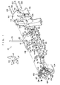
- FIG. 1 a perspective view is shown where relevant portions of a shift lever device 10 pertaining to a first embodiment of the invention are exploded.
- the shift lever device 10 is disposed with a housing 12.
- the housing 12 is disposed with an upper wall 14 formed by a synthetic resin material.
- the upper wall 14 is generally formed by a synthetic resin material such that the upper wall 14 has a plate shape whose thickness direction is along the vertical direction (the direction of arrow UP in FIG. 1 and the opposite direction) of the shift lever device 10 and also has a curved concave shape that opens substantially downward in the vertical direction.
- a shift groove 16 is formed in the upper wall 14.
- the shift groove 16 appropriately bends in the longitudinal direction (the direction of arrow FR in FIG. 1 and FIG 5 and the opposite direction) and in the width direction (the direction of arrow LF in FIG. 1 and FIG 5 and the opposite direction) of the upper wall 14, and penetrates the thickness direction of the upper wall 14.
- the lever body 22 is configured as a round rod whose outer diameter dimension is smaller than the width dimension of the shift groove 16, and an unillustrated knob for gripping is integrally fixed to the distal end portion of the lever body 22.
- a bracket 24 is integrally fixed to the proximal end portion of the lever body 22.
- the bracket 24 is disposed with a block-shaped body 26.
- a cylinder 28 is integrally formed on the body 26.
- the cylinder 28 is formed in a bottomed cylinder shape where the cross-sectional shape of the inner peripheral portion is circular and the upper end is open, and as shown in FIG. 4 , a compression coil spring 30 is housed inside the cylinder 28.
- a moderating pin 32 is housed in the cylinder 28 further toward the upper end side of the cylinder 28 than the compression coil spring 30.
- the moderating pin 32 is formed in a substantially hemispherical column shape and is biased toward the upper end side of the cylinder 28 by the biasing force of the compression coil spring 30.
- An unillustrated moderating groove is formed in the underside of the upper wall 14 in correspondence to the distal end of the moderating pin 32.
- the moderating groove is formed in a shape similar to that of the shift groove 16, but in contrast to the shift groove 16, does not penetrate the upper wall 14 but is configured as a bottomed groove that opens to the underside of the upper wall 14, so that the distal end of the moderating pin 32 pressingly contacts the bottom portion of the moderating groove by the biasing force of the compression coil spring 30.
- the bottom portion (upper bottom portion) of the moderating groove is configured as a slanted surface that appropriately slants with respect to the surface (top side) of the upper wall 14.
- leg plates 34 and 36 extend from the lower surface of the body 26 of the bracket 24 toward the side opposite from the lever body 22.
- the leg plate 34 extends from the lower end portion of the body 26 along the end portion of the body 26 at one side (in the present embodiment, the side opposite from arrow FR in FIG. 1 ) along the longitudinal direction of the upper wall 14.
- the leg plate 34 is configured as a narrow plate whose thickness direction is along the longitudinal direction of the upper wall 14.
- the leg plate 36 extends from the lower end portion of the body 26 along the end portion of the body 26 at the other side (in the present embodiment, the arrow FR side in FIG. 1 ) along the longitudinal direction of the upper wall 14.
- the leg plate 36 is also configured as a narrow plate whose thickness direction is along the longitudinal direction of the upper wall 14.
- a substantially hook-shaped inhibiting piece 38 is formed continuously from the lower end portion of the leg plate 36.
- a shift lock device (not shown) is disposed in the shift lever device 10 in correspondence to the inhibiting piece 38, and when the shift lock device is actuated and is inhibited by the inhibiting piece 38, the shift lock device regulates the rotation of the shift lever 20 from a predetermined shift position (e.g., position "P" in FIG 5 ).
- circular column-shaped pins 40 serving as rotating shafts respectively protrude coaxially with each other from the surface of the leg plate 34 opposite from the side facing the leg plate 36 and from the surface of the leg plate 36 opposite from the side facing the leg plate 34.
- a bearing member 42 is disposed on one side of the leg plates 34 and 36 along the width direction of the upper wall 14, and a bearing member 44 is disposed on the other side.
- the orientations of the bearing members 42 and 44 along the width direction of the upper wall 14 are opposite but their structures are the same. Consequently, just the structure of the bearing member 42 will be described, and description in relation to the structure of the bearing member 44 will be omitted.
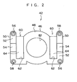
- the bearing member 42 is disposed with a body 46.
- the body 46 is formed in a block shape having a substantially elliptical shape in front view (i.e., a shape where both of the short edges of a rectangle are curved such that they stick outward).
- the width dimension of the body 46 is just slightly smaller than the distance between the leg plate 34 and the leg plate 36, and the body 46 is fitted between the leg plate 34 and the leg plate 36 in a state where its width direction is along the direction in which the leg plate 34 and the leg plate 36 face each other, that is, along the longitudinal direction of the upper wall 14.
- mutually facing end surfaces 48 of both of the bodies 46 abut against each other at substantial width-direction center portions of the leg plates 34 and 36.
- the end surfaces 48 of both of the bodies 46 abut against each other in a state where they are positioned in the substantial width-direction centers of the leg plates 34 and 36 in a state where both of the bodies 46 have been fitted between the leg plates 34 and 36 in this manner, but the configuration of the bearing member 42 is not limited to this.
- the end surfaces 48 of both of the bodies 46 may be displaced further toward either side in the width direction of the leg plates 34 and 36 than the substantial width-direction centers thereof, or the end surface 48 of one of the bodies 46 may be separated from the end surface 48 of the other of the bodies 46.
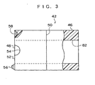
- a support 50 is disposed on each width-direction sides of the body 46.
- the supports 50 are formed in block shapes having a width that is smaller than that of the body 46. End surfaces 52 of the supports 50 facing the same direction as the end surface 48 of the body 46 are in the same position as the end surface 48 of the body 46 along the thickness direction of the body 46.
- Substantially semicircular cutout portions 54 serving as support portions are formed in the end surfaces 52.
- the radial dimensions (radii of curvature) of the cutout portions 54 are just slightly larger than the radial dimensions of the outer peripheral portions of the pins 40.
- the pins 40 shown in FIG. 1 enter the circular holes formed by the cutout portions 54 of both, and the pins 40 are supported by the circular holes such that the pins 40 are rotatable about their own axes.
- a joining protrusion 56 protrudes from one longitudinal-direction end side of the end surface 52 of the support 50 disposed on one width-direction side of the body 46. Further, a joining hole 58 whose inner diameter dimension is just slightly larger than the outer diameter dimension of the joining protrusion 56 (i.e., such that they can be fitted together) is formed in the other longitudinal-direction end side of the end surface 52 of this support 50.
- a joining protrusion 56 and a joining hole 58 are formed at the end surface 52 of the support 50 disposed on the other width-direction side of the body 46.
- the joining hole 58 in the support 50 disposed on the other width-direction side of the body 46 is formed in the one longitudinal-direction end side of the end surface 52, and the joining protrusion 56 is formed on the other longitudinal-direction end side of the end surface 52.
- the bearing member 42 and the bearing member 44 have identical shapes but their orientations along the width direction of the upper wall 14 are opposite. Consequently, in a state where the end surfaces 48 of the bodies 46 of both of the bearing members 42 and 44 face each other coaxially (i.e., such that the body 46 of the bearing member 44 is not shifted in either the longitudinal direction or the width direction with respect to the body 46 of the bearing member 42), the joining protrusions 56 formed on the bearing member 42 coaxially face the joining holes 58 formed in the bearing member 44, and the joining holes 58 formed in the bearing member 42 coaxially face the joining protrusions 56 formed on the bearing member 44.
- an adhesive is applied to the end surfaces 52 of at least either one of the bearing members 42 and 44 and to the joining protrusions 56 and the inner peripheral portions of the joining holes 58 formed at these end surfaces 52, so that when both of the bodies 46 of the bearing members 42 and 44 are fitted between the leg plates 34 and 36 and both end surfaces 48 and both end surfaces 52 abut against each other, the supports 50 of the bearing member 42 and the supports 50 of the bearing member 44 are joined together by the adhesive.
- coupling pieces 60 are disposed between the body 46 and both of the supports 50, and the body 46 and both of the supports 50 are integrally coupled together via the coupling pieces 60.
- Each of the coupling pieces 60 is configured by a horizontal plate 62 and a vertical plate 64 such that they have substantial "L" shapes when seen in side view.
- the horizontal plates 62 are coupled to the vertical plates 64 at end portions opposite from the end surfaces 48 and 52, and the dimension from the end surfaces of the vertical plates 64 at the side of the end surfaces 48 and 52 is sufficiently longer than half the width dimension of the leg plates 34 and 36, so that the leg plates 34 and 36 are not inhibited by the vertical plates 64 until the pins 40 supported in the circular holes formed by the cutout portions 54 of both the bearing members 42 and 44 rotate a predetermined angle about their axes.
- the shift lever device 10 is also disposed with a control lever 70 serving as a first lever member.
- the control lever 70 is disposed with a coupling piece 72.
- the coupling piece 72 is formed in a narrow plate shape whose thickness direction is along the width direction of the upper wall 14, and a hook-and-lock hole 74 is formed in the distal end side of the coupling piece 72.
- the hook-and-lock hole 74 penetrates the thickness direction of the coupling piece 72, and one end of a transmitting member (not shown) configured by a wire or a cable is hooked and locked in the hook-and-lock hole 74.
- the other end of the transmitting member is directly or indirectly connected to an automatic transmission (not shown) installed in the vehicle, and the automatic transmission is operated in accordance with the displacement amount of the transmitting member resulting from the rotation of the coupling piece 72 about an axis whose axial direction is the width direction of the upper wall 14 at the proximal end portion of the coupling piece 72.
- an inhibiting piece 76 is formed at the longitudinal-direction proximal end portion of the coupling piece 72.
- the inhibiting piece 76 is a direction slanted a predetermined angle with respect to the longitudinal direction of the coupling piece 72 around an axis whose axial direction is the width direction of the upper wall 14 is the longitudinal direction of, and a substantially "U" shaped inhibiting portion 78 is formed on the distal end side of the inhibiting piece 76 opening toward the proximal end thereof.
- the inhibiting portion 78 is configured such that a regulating member of a lock mechanism such as a rotation inhibiting mechanism or the like can fit therewith, and has a structure where, when the lock mechanism is actuated and the regulating member of the lock mechanism enters the inhibiting portion 78, the rotation of the inhibiting piece 76 and the coupling piece 72 about an axis whose axial direction is the width direction of the upper wall 14 is restricted.
- a regulating member of a lock mechanism such as a rotation inhibiting mechanism or the like can fit therewith, and has a structure where, when the lock mechanism is actuated and the regulating member of the lock mechanism enters the inhibiting portion 78, the rotation of the inhibiting piece 76 and the coupling piece 72 about an axis whose axial direction is the width direction of the upper wall 14 is restricted.
- a shaft 80 is formed at the proximal end portion of the coupling piece 72.
- the shape 80 is formed in a circular cylinder shape whose axial direction is the width direction of the upper wall 14, is open at its distal end portion, and is also open at the opposite end surface of the coupling piece 72 from the shaft 80 at the position where the shaft 80 joins to the coupling piece 72.
- insertion holes 82 are formed in the bodies 46 of both of the bearing members 42 and 44.
- the inner diameter dimensions of the insertion holes 82 are just slightly larger than the outer diameter dimension of the shaft 80, and the shaft 80 penetrates both of the insertion holes 82 in the bearing members 42 and 44.
- a first housing member 90 that is formed overall by a synthetic resin material is disposed on one width-direction side of the upper wall 14.
- the first housing member 90 is disposed with a side wall 92 whose thickness direction is along the width direction of the upper wall 14.
- the first housing member 90 is also disposed with a front wall 94.
- the thickness direction of the front wall 94 is generally along the longitudinal direction of the upper wall 14, and the width dimension of the front wall 94 along the same direction as the width direction of the upper wall 14 is set to be about the same as the width dimension of the upper wall 14. Moreover, an end portion of the front wall 94 at one side in the width direction of the upper wall 14 is connected to an end portion of the side wall 92 at one side in the longitudinal direction of the upper wall 14.
- the first housing member 90 is disposed with a rear wall 96.
- the thickness direction of the rear wall 96 is generally along the longitudinal direction of the upper wall 14, and the width dimension of the rear wall 96 along the same direction as the width direction of the upper wall 14 is set to be about 1 ⁇ 2 the width dimension of the upper wall 14.
- an end portion of the rear wall 96 at one side along the width direction of the upper wall 14 is connected to an end portion of the side wall 92 at the other side along the longitudinal direction of the upper wall 14.
- a second housing member 100 that is formed overall by a synthetic resin material is disposed on the other width-direction side of the upper wall 14.
- the second housing member 100 is disposed with a side wall 102 whose thickness direction is along the width direction of the upper wall 14.
- the second housing member 100 is disposed with a rear wall 104.
- the thickness direction of the rear wall 104 is generally along the longitudinal direction of the upper wall 14, and the width dimension of the rear wall 104 along the same direction as the width direction of the upper wall 14 is set to be about 1 ⁇ 2 the width dimension of the upper wall 14.
- an end portion of the rear wall 104 at one side along the width direction of the upper wall 14 is connected to an end portion of the side wall 102 at the other side along the longitudinal direction of the upper wall 14.
- the shape of this width-direction end surface of the rear wall 14 is substantially the same as the shape of the width-direction end surface of the rear wall 96 of the first housing member 90.
- coupling portions 106 extend from both width-direction end sides in the vicinity of one longitudinal-direction end portion of the upper wall 14 toward the underside (in FIG 1 , only one of the coupling portions 106 is shown). Through holes 108 that penetrate the coupling portions 106 along the width direction of the upper wall 14 are formed in the coupling portions 106 such that the through holes 108 are coaxial with each other. In correspondence to the coupling portions 106, a through hole 110 is formed in the side wall 92 of the first housing member 90 and a through hole 112 is formed in the side wall 102 of the second housing member 100.
- coupling portions 114 extend from both width-direction end sides in the vicinity of the other longitudinal-direction end portion of the upper wall 14 toward the underside.
- Through holes 116 that penetrate the coupling portions 114 along the width direction of the upper wall 14 are formed in the coupling portions 114 such that the through holes 116 are coaxial with each other.
- a through hole 118 is formed in the side wall 92 of the first housing member and a through hole 120 is formed in the side wall 102 of the second housing member 100.
- the through holes 110 and 112 become substantially coaxial with respect to the through holes 108, and the through holes 118 and 120 become substantially coaxial with respect to the through holes 116.
- fastening pins 122 are inserted through the through holes 110 and 118 from the side of the side wall 92 opposite from the side facing the upper wall 14.
- the distal end side of the fastening pin 122 inserted through the through hole 110 penetrates the through holes 108 and 112 and protrudes from the side of the side wall 102 opposite from the side facing the upper wall 14. Further, the distal end side of the fastening pin 122 inserted through the through hole 118 penetrates the through holes 116 and 120 and protrudes from the side of the side wall 102 opposite from the side facing the upper wall 14.
- Fasteners 124 are attached to the distal end sides of the fastening pins 122 protruding through the through holes 112 and 120, and the upper wall 14, the first housing member 90, and the second housing member 100 are fastened and fixed together by the fasteners 124 and the head portions of the fastening pins 122.
- an insertion hole 126 is formed in the side wall 92 and an insertion hole 128 is formed in the side wall 102.
- the insertion holes 126 and 128 are formed such that they are coaxial with each other in the fastened state (i.e., when the insertion holes 126 and 128 become coaxial, the through holes 110 and 112 become substantially coaxial with respect to the through holes 108, and the through holes 118 and 120 become substantially coaxial with respect to the through holes 116).
- the outer diameter dimension of the body portion of the fastening shaft 130 is set to be just smaller than the inner diameter dimension of the shaft 80.
- a fastener 124 is attached to the distal end portion of the fastening shaft 130 penetrating the insertion hole 128 and protruding from the side of the side wall 102 opposite from the side facing the upper wall 14, and the upper wall 14, the first housing member 90, and the second housing member 100 are fastened and fixed together by the fastener 124 and the head portion of the fastening shaft 130.
- the fastening pins 122 and the fastening shaft 130 are inserted through the through holes 110 and 118 and the insertion hole 126 in the side wall 92 of the first housing member 90.
- the bearing member 42 is attached to the fastening shaft 130 such that the fastening shaft 130 penetrating the insertion hole 126 penetrates the insertion hole 82 in the bearing member 42.
- the bracket 24 is attached to the bearing member 42 from the opposite side of the first housing member 90 to the side facing the side wall 92 such that the leg plates 34 and 36 of the bracket 24 sandwich the body 46 of the bearing member 42. Moreover, at about the same time as the action of attaching the bracket 24 with respect to the bearing member 42, the fastening pins 122 penetrating the through holes 110 and 118 in the side wall 92 are inserted through the through holes 108 and 116 in the coupling portions 106 and 114 of the upper wall 14.
- the bearing member 44 is attached via the bracket 24 such that the leg plates 34 and 36 are sandwiched by the body 46 and both of the supports 50.
- the fastening shaft 130 is inserted through the insertion hole 82 in the bearing member 44.
- the joining protrusions 56 enter the joining holes 58 such that relative displacement (i.e., "shifting") of the bearing member 44 with respect to the bearing member 42 in the direction orthogonal to the protruding direction of the joining protrusions 56 (i.e., the direction orthogonal to the axial direction of the fastening shaft 130) is prevented.
- an adhesive is applied to the end surfaces 52 of the supports 50 of at least either one of the bearing member 42 and the bearing member 44.
- the fastening pins 122 and the fastening shaft 130 are inserted through the through holes 112 and 120 and the insertion hole 128 in the side wall 102 of the second housing member 100.
- the fasteners 124 are attached to the distal ends of the fastening pins 122 and the fastening shaft 130.
- the work of assembling each of the members becomes, based on the fastening pins 122 and the fastening shaft 130, assembly from the distal end sides of the fastening pins 122 and the fastening shaft 130 to the proximal end (head portion) sides.
- each of the members can be assembled from one direction
- these members can be assembled while maintaining the orientation of the first housing member 90 - to which the assembly of the bearing members 42 and 44, the bracket 24, and the second housing member 100 are easily assembled - such as a state where the distal ends of the fastening pins 122 and the fastening shaft 130 penetrating the through holes 110 and 118 and the insertion hole 126 in the side wall 92 of the first housing member 90 face up, for example.
- the operability of the assembly work can be extremely effectively improved.
- the shift lever device 10 can be assembled by assembling each of the members in order from the same direction. For this reason, when the assembly of the shift lever device 10 is automated by an automatic assembly device such as a robot, the operation of the robot arm or the like, for example, can be made into a simple operation such as a one-dimensional operation. As a result, the structure of the automatic assembly device such as a robot can be compacted and simplified, and the cost of the automatic assembly device itself can be made inexpensive.
- bracket 24 of the lever body 22 and the control lever 70 are coupled together by assembling the bearing members 42 and 44 prior to assembling the second housing member 100. For this reason, the structure of the second housing member 100 does not inadvertently inhibit the lever body 22 or the control lever 70 during the work of coupling together the lever body 22 and the control lever 70.
- the structure of the first housing member 90 does not inadvertently inhibit the lever body 22 or the control lever 70 during the work of coupling together the lever body 22 and the control lever 70.
- the pins 40 - and therefore the lever body 22 - are supported in the circular holes that are formed by causing the cutout portions 54 of the supports 50 formed in the bearing members 42 and 44 to face each other. Yet until the bearing member 42 and the bearing member 44 are joined together, the circular holes that support the pins 40 are basically nothing more than the semicircular cutout portions 54.
- the pins 40 are not particularly inhibited, and in regard to fitting the pins 40 into the cutout portions 54 of the supports 50 of the bearing member 44, the pins 40 are not particularly inhibited.
- the lever body 22 and the control lever 70 can be easily coupled together, and in this sense also, the operability during the assembly work can be extremely effectively improved.
- control lever 70 is axially supported by the fastening shaft 130 for fastening and fixing together the first housing member 90 and the second housing member 100. For this reason, the overall number of parts can be reduced.
- the material strength of the fastening shaft 130 is stronger than that of the first housing member 90 and the second housing member 100, the first housing member 90 and the second housing member 100 can be reliably fastened and fixed together, and because the fastening shaft 130 is strong in this manner, it can reliably support the control lever 70 without breaking or sustaining damage due to the rotation of the control lever 70.
- control lever 70 can be reliably supported by the materially strong fastening shaft 130 alone, strength necessary to support the control lever 70 does not have to be given to the first housing member 90 and the second housing member 100. For this reason, the housing 12 can be made lightweight, and therefore the shift lever device 10 as a whole can be made lightweight.
- FIG. 6 the basics of the configuration of relevant portions of a shift lever device I50 pertaining to the present embodiment are shown by cross-sectional view.
- a shift lever 152 is disposed between the side wall 92 of the first housing member 90 and the side wall 102 configuring the second housing member 100 that configure the housing 12.
- the shift lever 152 is disposed with a lever body 154 that has a substantially circular bottomed cylinder shape (pipe shape).
- a detent rod 156 is housed inside the lever body 154.
- the detent rod 156 is configured as a long rod along the longitudinal direction of the lever body 154.
- a compression coil spring 158 is disposed between the longitudinal-direction proximal end portion (lower end portion) of the detent rod 156 and the inner bottom portion of the lever body 154, and the detent rod 156 is biased by the biasing force of the compression coil spring 158 toward the distal end side (upward in FIG. 6 ) of the lever body 154.
- the distal end portion of the detent rod 156 enters the inside of a knob (not shown) attached to the distal end portion of the lever body 154.
- a release button (not shown) is attached to the knob, so that when the release button is pushed, the detent rod 156 moves (downward) toward the inner bottom portion of the lever body 154 counter to the biasing force of the compression coil spring 158.
- a slit hole 160 is formed in the longitudinal-direction intermediate portion of the lever body 154.
- the slit hole 160 is configured as a long hole along the longitudinal direction of the lever body 154 and allows the inside and outside of the lever body 154 to be communicated.
- a detent pin 162 that protrudes from the outer peripheral portion of the detent rod 156 penetrates the slit hole 160.
- Detent holes 164 are formed in the side walls 92 and 102 in correspondence to the distal end sides of the detent pin 162, and the distal ends of the detent pin 162 penetrating the slit hole 160 enter the detent holes 164.
- the inner peripheral portion positioned at the upper side of the detent holes 164 appropriately protrude downward, and these protruding portions inhibit the detent pin 162, whereby the movement of the detent pin 162 to the side of the protruding portions is restricted and the movement of the shift lever 152 is indirectly restricted.
- the restricted state can be released by pushing the release button as described above in this restricted state and causing the detent rod 156 to move to a position where it can avoid inhibition by the protruding portions.
- a cylindrical portion 166 is disposed on the proximal end portion of the lever body 154.
- the cylindrical portion 166 is configured to be long along the direction orthogonal to the longitudinal direction of the lever body 154 and along the direction in which the side wall 92 and the side wall 102 face each other, and the proximal end portion of the lever body 154 is integrally coupled to the outer peripheral portion of the longitudinal-direction intermediate portion of the cylindrical portion 166 (in FIG. 6 , substantially the center).
- a cross-sectionally circular insertion hole 168 is formed in the axial center portion of the cylindrical portion 166, and fit-insertion holes 170 whose inner diameter dimensions are larger than that of the insertion hole 168 are formed in both longitudinal- (axial-) direction end sides of the cylindrical portion 166 coaxially with respect to the insertion hole 168 and the cylindrical portion 166.
- the positioning portions 172 are formed in substantially circular cylinder shapes whose outer diameter dimensions are smaller than the inner diameter dimensions of the fit-insertion holes 170, so that by inserting the positioning portions 172 into the fit-insertion holes 170 when the shift lever device 150 is to be assembled, the shift lever 152 is positioned with respect to the first housing member 90 and the second housing member 100.
- insertion holes 126 are formed coaxially in the positioning portions 172, and the insertion holes 126 are open at the distal end portions of the positioning portions 172. Both of the insertion holes 126 are coaxially continuous with respect to the insertion hole 168 in a state where the positioning portions 172 have been fit-inserted into the fit-insertion holes 170, and the fastening shaft 130 inserted through the insertion hole 126 in the side wall 92 penetrates the insertion hole 168 to support the cylindrical portion 166 (i.e., the shift lever 152) such that the cylindrical portion 166 is rotatable about the fastening shaft 130.
- the cylindrical portion 166 i.e., the shift lever 152
- the present shift lever device 150 is a "straight" shift lever device 150 that is rotatingly operated only about the fastening shaft 130, and when the shift lever 152 reaches a predetermined rotational position (shift position) about the fastening shaft 130, the shift range is changed to a shift range corresponding to the rotational position of the shift lever 152 among plural shift ranges set in the automatic transmission.
- the fastening shaft 130 penetrating the insertion hole 168 penetrates the insertion hole 126 formed in the side wall 102, and the fastener 124 is attached thereto such that the upper wall 14 (not shown in FIG. 6 ), the first housing member 90, and the second housing member 100 are fastened and fixed together by the fastener 124 and the head portion of the fastening shaft 130.
- the work of passing the lever body 154 through the shift groove 16 can be excluded, the work of assembling each of the members becomes, assembly building around the fastening pins 122 (not shown in FIG 6 ) and the fastening shaft 130, from the distal end sides of the fastening pins 122 and the fastening shaft 130 to the proximal end (head portion) sides thereof,.
- each of the members can be assembled from one direction
- these members can be assembled while maintaining the orientation of the first housing member 90 - to which the assembly of the second housing member 100 and the like are easily assembled - such as a state where the distal ends of the fastening pins 122 and the fastening shaft 130 penetrating the through holes 110 and 118 (not shown in FIG 6 ) and the insertion hole 126 in the side wall 92 of the first housing member 90 face up, for example.
- the operability of the assembly work can be extremely effectively improved.
- the shift lever device 150 can be assembled by assembling each of the members in order from the same direction. For this reason, when the assembly of the shift lever device 150 is automated by an automatic assembly device such as a robot, the operation of the robot arm or the like, for example, can be made into a simple operation such as a one-dimensional operation. As a result, the structure of the automatic assembly device such as a robot can be made compact and simplified, and the cost of the automatic assembly device itself can be made inexpensive.
- the shift lever 152 is rotatably axially supported by the fastening shaft 130 for fastening and fixing together the first housing member 90 and the second housing member 100.
- the material strength of the fastening shaft 130 is higher than that of the first housing member 90 and the second housing member 100.
- the positioning portions 172 and the like of the first housing member 90 and the second housing member 100 can simply be used just for positioning when assembling the shift lever 152, and do not have to contribute to mechanical strength at a time of supporting the shift lever 152.
- the housing 12 can be made lightweight, and therefore the shift lever device 10 as a whole can be made lightweight.
Landscapes
- Engineering & Computer Science (AREA)
- General Engineering & Computer Science (AREA)
- Mechanical Engineering (AREA)
- Arrangement Or Mounting Of Control Devices For Change-Speed Gearing (AREA)
- Gear-Shifting Mechanisms (AREA)
Applications Claiming Priority (2)
| Application Number | Priority Date | Filing Date | Title |
|---|---|---|---|
| JP2004123138A JP4497994B2 (ja) | 2004-04-19 | 2004-04-19 | シフトレバー装置 |
| PCT/JP2005/005857 WO2005102763A1 (ja) | 2004-04-19 | 2005-03-29 | シフトレバー装置 |
Publications (3)
| Publication Number | Publication Date |
|---|---|
| EP1741592A1 EP1741592A1 (en) | 2007-01-10 |
| EP1741592A4 EP1741592A4 (en) | 2009-02-04 |
| EP1741592B1 true EP1741592B1 (en) | 2010-04-28 |
Family
ID=35196842
Family Applications (1)
| Application Number | Title | Priority Date | Filing Date |
|---|---|---|---|
| EP05727543A Ceased EP1741592B1 (en) | 2004-04-19 | 2005-03-29 | Shift lever device |
Country Status (6)
| Country | Link |
|---|---|
| US (1) | US8720293B2 (enExample) |
| EP (1) | EP1741592B1 (enExample) |
| JP (1) | JP4497994B2 (enExample) |
| CN (1) | CN100484799C (enExample) |
| DE (1) | DE602005020920D1 (enExample) |
| WO (1) | WO2005102763A1 (enExample) |
Families Citing this family (11)
| Publication number | Priority date | Publication date | Assignee | Title |
|---|---|---|---|---|
| JP5123252B2 (ja) * | 2009-05-26 | 2013-01-23 | 株式会社東海理化電機製作所 | シフトレバー装置 |
| KR101305787B1 (ko) * | 2011-07-29 | 2013-09-06 | 현대자동차주식회사 | 통합 제어 변속레버장치 |
| KR20130017724A (ko) * | 2011-08-11 | 2013-02-20 | 현대자동차주식회사 | 변속기의 변속 조작장치 |
| JP2014004974A (ja) * | 2012-06-27 | 2014-01-16 | Fuji Kiko Co Ltd | シフトレバー装置 |
| JP6126910B2 (ja) * | 2013-05-24 | 2017-05-10 | 株式会社東海理化電機製作所 | シフト装置 |
| DE112014004064T5 (de) | 2013-09-06 | 2016-06-02 | Kongsberg Automotive Ab | Schaltvorrichtung mit einer Sensoranordnung |
| KR101534930B1 (ko) * | 2013-10-17 | 2015-07-27 | 현대자동차주식회사 | 자동변속기 차량용 변속레버 조립체 및 이의 조립방법 |
| JP6013387B2 (ja) * | 2014-03-14 | 2016-10-25 | トヨタ自動車株式会社 | 車両用シフト操作装置 |
| JP6496589B2 (ja) * | 2015-03-27 | 2019-04-03 | 株式会社アツミテック | 車両用変速操作装置 |
| JP6306774B2 (ja) * | 2017-04-28 | 2018-04-04 | 株式会社東海理化電機製作所 | シフト装置 |
| CN109990082A (zh) * | 2017-12-29 | 2019-07-09 | 重庆市永川区邦威机械制造有限公司 | 一种汽车变速器换挡机构 |
Family Cites Families (15)
| Publication number | Priority date | Publication date | Assignee | Title |
|---|---|---|---|---|
| JPS59162329U (ja) * | 1983-04-16 | 1984-10-30 | 三菱自動車工業株式会社 | 動力援助変速装置の変速操作信号発生装置 |
| JPH0121374Y2 (enExample) * | 1984-12-28 | 1989-06-26 | ||
| JPH0356106Y2 (enExample) * | 1985-12-19 | 1991-12-16 | ||
| JPH0429153Y2 (enExample) * | 1986-09-19 | 1992-07-15 | ||
| US4875383A (en) * | 1989-02-23 | 1989-10-24 | Dana Corporation | Dual ratio transmission shifter assembly with neutral safety switch |
| US5490434A (en) * | 1994-01-28 | 1996-02-13 | Grand Haven Stamped Products | Vehicle transfer case shifter system |
| US5749268A (en) * | 1994-02-21 | 1998-05-12 | Sega Enterprises, Ltd. | Simulating multi-stage speed change shift lever operating device |
| JP3167958B2 (ja) * | 1997-05-08 | 2001-05-21 | コナミ株式会社 | 多方向切替操作装置 |
| JP3558111B2 (ja) * | 1997-08-29 | 2004-08-25 | 富士機工株式会社 | 自動変速機操作装置 |
| JP2000038047A (ja) * | 1998-07-22 | 2000-02-08 | Tokai Rika Co Ltd | シフトレバー装置 |
| JP2000043600A (ja) * | 1998-07-30 | 2000-02-15 | Tokai Rika Co Ltd | シフトレバー |
| JP3557123B2 (ja) * | 1999-05-18 | 2004-08-25 | 富士機工株式会社 | 樹脂成形品のボルト締結構造 |
| US6550351B1 (en) | 1999-08-06 | 2003-04-22 | Stoneridge Control Devices, Inc. | Transmission range selector system |
| JP3958917B2 (ja) | 2000-07-18 | 2007-08-15 | 株式会社アツミテック | 車両用変速操作装置 |
| JP4002849B2 (ja) * | 2003-02-21 | 2007-11-07 | カルソニックカンセイ株式会社 | 車両用自動変速操作装置の操作レバー構造 |
-
2004
- 2004-04-19 JP JP2004123138A patent/JP4497994B2/ja not_active Expired - Fee Related
-
2005
- 2005-03-29 CN CNB2005800117762A patent/CN100484799C/zh not_active Expired - Fee Related
- 2005-03-29 EP EP05727543A patent/EP1741592B1/en not_active Ceased
- 2005-03-29 WO PCT/JP2005/005857 patent/WO2005102763A1/ja not_active Ceased
- 2005-03-29 US US11/578,976 patent/US8720293B2/en not_active Expired - Fee Related
- 2005-03-29 DE DE602005020920T patent/DE602005020920D1/de not_active Expired - Lifetime
Also Published As
| Publication number | Publication date |
|---|---|
| CN1942334A (zh) | 2007-04-04 |
| CN100484799C (zh) | 2009-05-06 |
| US20070214907A1 (en) | 2007-09-20 |
| JP2005306106A (ja) | 2005-11-04 |
| EP1741592A1 (en) | 2007-01-10 |
| WO2005102763A1 (ja) | 2005-11-03 |
| JP4497994B2 (ja) | 2010-07-07 |
| US8720293B2 (en) | 2014-05-13 |
| DE602005020920D1 (de) | 2010-06-10 |
| EP1741592A4 (en) | 2009-02-04 |
Similar Documents
| Publication | Publication Date | Title |
|---|---|---|
| EP1741592B1 (en) | Shift lever device | |
| US6318206B1 (en) | Shift rocker | |
| US11009129B2 (en) | Vehicle parking apparatus | |
| KR101954191B1 (ko) | 이중 힌지를 이용한 변속제어장치 | |
| JP2006273054A (ja) | シフトレバー装置 | |
| JPH0536730Y2 (enExample) | ||
| JPH11189061A (ja) | 自動変速機用コラムシフト装置 | |
| JPH0514938Y2 (enExample) | ||
| JP3358984B2 (ja) | 自動変速機用コラムシフト装置 | |
| JP4378007B2 (ja) | 車両用ドアハンドル装置 | |
| JPH06174060A (ja) | 自動変速機用変速操作レバーのレバー本体 | |
| KR100736954B1 (ko) | 자동변속기 | |
| CN112721627B (zh) | 用于车辆的换挡杆总成 | |
| JP4698988B2 (ja) | シフトレバー装置 | |
| KR100792824B1 (ko) | 스티어링 시스템용 기어박스의 마운팅부시 | |
| JP3358848B2 (ja) | 自動変速機のディテント機構 | |
| JP3528344B2 (ja) | 車両用自動変速機のシフト装置 | |
| US11441672B2 (en) | Adjustable shift lever mount | |
| JP4166330B2 (ja) | ゲート式シフトレバー装置 | |
| JP2007302246A (ja) | 自動二輪車のサイドスタンド装置 | |
| JP3655988B2 (ja) | 自動変速機のディテントスプリング取付構造 | |
| JP3193002B2 (ja) | 車両用a/tシフトレバー装置 | |
| KR940006834A (ko) | 자동차용 수동 변속기의 변속레버장치 | |
| KR20250160999A (ko) | 슬라이드 스위치 및 이를 구비하는 조작 레버 장치 | |
| JPH0477177B2 (enExample) |
Legal Events
| Date | Code | Title | Description |
|---|---|---|---|
| PUAI | Public reference made under article 153(3) epc to a published international application that has entered the european phase |
Free format text: ORIGINAL CODE: 0009012 |
|
| 17P | Request for examination filed |
Effective date: 20061021 |
|
| AK | Designated contracting states |
Kind code of ref document: A1 Designated state(s): DE FR GB |
|
| DAX | Request for extension of the european patent (deleted) | ||
| RBV | Designated contracting states (corrected) |
Designated state(s): DE FR GB |
|
| A4 | Supplementary search report drawn up and despatched |
Effective date: 20090109 |
|
| RIC1 | Information provided on ipc code assigned before grant |
Ipc: F16H 59/02 20060101AFI20090807BHEP |
|
| GRAP | Despatch of communication of intention to grant a patent |
Free format text: ORIGINAL CODE: EPIDOSNIGR1 |
|
| RIN1 | Information on inventor provided before grant (corrected) |
Inventor name: KATO, MASASHIK. K. TOKAI-RIKA-DENKI-SEISAKUSHO Inventor name: YOKOYAMA, YOSHINOBUK. K. TOKAI-RIKA-DENKI-SEISAKUS |
|
| GRAS | Grant fee paid |
Free format text: ORIGINAL CODE: EPIDOSNIGR3 |
|
| GRAA | (expected) grant |
Free format text: ORIGINAL CODE: 0009210 |
|
| AK | Designated contracting states |
Kind code of ref document: B1 Designated state(s): DE FR GB |
|
| REG | Reference to a national code |
Ref country code: GB Ref legal event code: FG4D |
|
| REF | Corresponds to: |
Ref document number: 602005020920 Country of ref document: DE Date of ref document: 20100610 Kind code of ref document: P |
|
| PLBE | No opposition filed within time limit |
Free format text: ORIGINAL CODE: 0009261 |
|
| STAA | Information on the status of an ep patent application or granted ep patent |
Free format text: STATUS: NO OPPOSITION FILED WITHIN TIME LIMIT |
|
| 26N | No opposition filed |
Effective date: 20110131 |
|
| REG | Reference to a national code |
Ref country code: FR Ref legal event code: PLFP Year of fee payment: 11 |
|
| REG | Reference to a national code |
Ref country code: DE Ref legal event code: R084 Ref document number: 602005020920 Country of ref document: DE |
|
| REG | Reference to a national code |
Ref country code: FR Ref legal event code: PLFP Year of fee payment: 12 |
|
| REG | Reference to a national code |
Ref country code: FR Ref legal event code: PLFP Year of fee payment: 13 |
|
| REG | Reference to a national code |
Ref country code: FR Ref legal event code: PLFP Year of fee payment: 14 |
|
| PGFP | Annual fee paid to national office [announced via postgrant information from national office to epo] |
Ref country code: GB Payment date: 20180329 Year of fee payment: 14 |
|
| PGFP | Annual fee paid to national office [announced via postgrant information from national office to epo] |
Ref country code: FR Payment date: 20180223 Year of fee payment: 14 |
|
| PGFP | Annual fee paid to national office [announced via postgrant information from national office to epo] |
Ref country code: DE Payment date: 20190319 Year of fee payment: 15 |
|
| GBPC | Gb: european patent ceased through non-payment of renewal fee |
Effective date: 20190329 |
|
| PG25 | Lapsed in a contracting state [announced via postgrant information from national office to epo] |
Ref country code: GB Free format text: LAPSE BECAUSE OF NON-PAYMENT OF DUE FEES Effective date: 20190329 |
|
| PG25 | Lapsed in a contracting state [announced via postgrant information from national office to epo] |
Ref country code: FR Free format text: LAPSE BECAUSE OF NON-PAYMENT OF DUE FEES Effective date: 20190331 |
|
| REG | Reference to a national code |
Ref country code: DE Ref legal event code: R119 Ref document number: 602005020920 Country of ref document: DE |
|
| PG25 | Lapsed in a contracting state [announced via postgrant information from national office to epo] |
Ref country code: DE Free format text: LAPSE BECAUSE OF NON-PAYMENT OF DUE FEES Effective date: 20201001 |