EP1730819B1 - Elektrisches nullkraftsteckverbindungsteil - Google Patents
Elektrisches nullkraftsteckverbindungsteil Download PDFInfo
- Publication number
- EP1730819B1 EP1730819B1 EP05716394A EP05716394A EP1730819B1 EP 1730819 B1 EP1730819 B1 EP 1730819B1 EP 05716394 A EP05716394 A EP 05716394A EP 05716394 A EP05716394 A EP 05716394A EP 1730819 B1 EP1730819 B1 EP 1730819B1
- Authority
- EP
- European Patent Office
- Prior art keywords
- contact
- sleeve
- force
- zero
- plug
- Prior art date
- Legal status (The legal status is an assumption and is not a legal conclusion. Google has not performed a legal analysis and makes no representation as to the accuracy of the status listed.)
- Expired - Lifetime
Links
Images

Classifications
-
- H—ELECTRICITY
- H01—ELECTRIC ELEMENTS
- H01R—ELECTRICALLY-CONDUCTIVE CONNECTIONS; STRUCTURAL ASSOCIATIONS OF A PLURALITY OF MUTUALLY-INSULATED ELECTRICAL CONNECTING ELEMENTS; COUPLING DEVICES; CURRENT COLLECTORS
- H01R13/00—Details of coupling devices of the kinds covered by groups H01R12/70 or H01R24/00 - H01R33/00
- H01R13/02—Contact members
- H01R13/193—Means for increasing contact pressure at the end of engagement of coupling part, e.g. zero insertion force or no friction
Definitions
- the invention relates to an electrical zero-force plug connection part which has one or more sleeve contact (s), each having at least one contact area, designed in each case for receiving a complementary electrical plug contact, wherein the sleeve contact (s) is assigned an activating element which is adjustable with respect to this / these, in that the contact force is applied to the contact area (s) of the sleeve contact (s) in the activated position for contacting each of a plug contact inserted into a respective sleeve contact.
- Zero-force connectors are used in electronic devices for contacting individual modules, flex films and printed circuit boards.
- the term "zero force connector” or “zero force connector part” is used because these connector parts can be contacted without effort.
- Out DE 197 42 400 A1 is a printed circuit board zero-force connector known, which serves for the connection of two circuit boards.
- This zero-force connector has a receptacle for inserting the edge to be contacted of a printed circuit board.
- This printed circuit board is inserted into a plug-in slot of the zero-force connector.
- This zero force connector has two connector halves pivotable toward and away from each other. The printed circuit board to be contacted is used in a position of the connector halves in which they are pivoted away from one another.
- the zero-force connector described in this document is not suitable for forming a multi-pole, in particular multi-row connector.
- Such connectors are used for example in the automotive sector, such as for contacting control units or for connecting the integrated in the dashboard electrical / electronic assemblies to the electrical system. Due to the multipolar nature of these connectors, there is a desire to be able to use even for such connector zero-force connector parts. The force required to bring together multi-pole complementary connector parts is not insignificant.
- joining aids such as levers or the like have been developed with which two connector parts can be brought into electrical connection with a reasonable effort with each other.
- joining aids In many places within a motor vehicle, in which multipolar connector parts must be connected to each other, however, there is not enough installation space to accommodate a connector part with such a mounting aid or to leave enough space to operate such a mounting aid can.
- the U.S. Patent 3,710,304 shows a connector with sleeve contacts, which are compressed by manual operation of a push button via a toggle mechanism, so as to clamp the inserted contacts of a mating connector.
- the U.S. Patent 6,083,023 shows an electrical zero force connector part according to the preamble of claim 1.
- this connector part common activation elements for each of a number of sleeve contacts are present.
- the activating be moved in the course of assembly of the connector part with a matching mating connector part perpendicular to the direction of insertion in its activated position. This displacement is effected by attached to the ends of the activating cams, which follow associated with the assembly of the connector parts, molded in the housing of the mating connector cam tracks.
- each sleeve contact is associated with an activating element configured as an over-spring.
- the electrical zero force connector part according to the invention has a plurality of individual sleeve contacts, each with one, suitably a plurality of contact areas.
- the contact regions may be formed as a contact bead and / or as a contact bead.
- the contact sockets are designed to receive a plug contact in their plug receptacle, expediently designed as a blade contact.
- the sleeve contacts each have an activating element associated, which is adjustable relative to the sleeve contact. Such adjustability between the activating element and the sleeve contact can be realized for example by a relative longitudinal displacement of the two elements to each other.
- each sleeve contact serves the purpose of applying the contact force required for proper contacting to the contact regions of the sleeve contact when the plug contact is inserted.
- This contact force is applied by the activating element to the sleeve contact in its activated position. If the activating element is not activated, the force applied to the sleeve contact consequently does not act on the force applied by the activating element for intended contact. Consequently, a plug contact can be inserted virtually powerless in the sleeve contact with activated activating element.
- the activating element is designed such that in its non-activated position, the contact region of the sleeve contact is lifted off the electrical surface of a plug contact inserted or to be inserted into the plug receptacle of the sleeve contact.
- the desired contact force is applied to the contact area of a sleeve contact by activating the activating.
- activation of the activating element can according to a Embodiment be coupled to the insertion movement of the connector part.
- the activating element is actuated together with a secondary locking.
- An expedient embodiment of such a sleeve contact has two contact lamellae which lie opposite one another with respect to the connector receptacle and each have two contact regions which are separated from one another by a contact lamella portion bulged outwards toward the activating element.
- the obliquely extending surfaces of the bulge serve as a setting bevel for each one actuating cam of the activating element, which acts in the activated position of the activating element on the central region of the bulge.
- the arrangement of a parking cam in the central region of the bulge with activated activating equally brings the desired contact force on both adjacent contact areas on.
- the activating In the event that are lifted by the activating the contact areas or in the non-activated position of the surface of a plug contact used in the plug receptacle, and the activating is designed as a sheet metal part, pointing to the plug receptacle sides of the activating are suitably coated electrically insulating ,
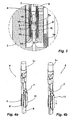
- a connector 1 comprises a two-pole Nullkraftsteckitatisteil 2, which is designed as a female part and a complementary, the plug contacts carrying plug connection part 3.
- the connector part 3 is formed in the illustrated embodiment of the outer wall of a control unit, which is otherwise not shown in detail.
- the electrical conductors L 1 , L 2 are connected with their front extending into the connector part 2 end to a respective sleeve contact, as shown in the sectional view of FIG. 2a is recognizable.
- the sleeve contact is identified by the reference numeral 4.
- the sleeve contact 4 has two contact blades 5, 5 ', between which a plug contact receptacle is arranged. In the plug contact recording designed as a blade contact plug contact 6 of the complementary connector part 3 is inserted.
- the sleeve contact 4 has in its at the contact blades 5, 5 'adjacent and connecting them together section via a Primärverriegelungsaus principleung 7, in which a locking pin 8 is arranged engaging (see. FIG. 2b ).
- the locking pin 8 is part of a housing 9 belonging to the connector part 2 insert 10th
- Belonging to the sleeve contact 4 is designed as an over-spring activating element 11, which in particular in the enlarged view of FIG. 3 is recognizable.
- the activating element 11 is a sheet metal part and closes the contact blades 5, 5 'in the manner of a cage.
- the contact blades 5, 5 ' are constructed identically; For this reason, the activating element 11 of the illustrated embodiment is also constructed with respect to its over-spring properties with respect to the contact blades 5, 5 'similar to its two, each with a contact blade 5 and 5' cooperating sides. In the following, only the contact blade 5 and the portion of the activating element 11 is described, which is associated with the contact blade 5. The relevant statements apply to the contact blade 5 'accordingly.
- the contact blade 5 comprises two contact areas K 1 , K 2 , which are each formed by a bead carrying a contact bead.
- the contact areas K 1 , K 2 serve to contact the surface of the plug contact 6 inserted into the plug contact receptacle of the sleeve contact 4.
- the contact area K 1 is located at the lower end of the contact blade 5, leaving an actuating extension 12.
- the contact area K 2 is at a distance from the contact area K. 1 .
- Between the two contact areas K 1 , K 2 is an outward bulge 13, formed by two inclined to the apex of the bulge 13 extending surfaces.
- the activating element 11 has at its lower end a U-shaped adjusting tab 14, which engages behind the actuating extension 12 of the contact blade 5, as this in FIG.
- the adjusting tab 14 serves to lift the contact blade 5 with their contact areas K 1 , K 2 from the surface of the plug contact 6 in the in the FIGS. 2a, 2b and 3
- a further adjusting tab 15 which is a U-shaped fold of the activating element 11 and is guided around behind the contact blade 5 around them, so that the adjusting tab 5 between the side facing the plug contact 6 side of the contact blade 5 and the plug contact 6 is arranged.
- the adjusting flap 15 is located in the in FIG.
- the activating element 11 has a positioning cam 16, which in the illustrated exemplary embodiment is arranged adjacent to the adjusting tab 15 on the other upper side of the contact blade 5.
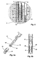
- FIG. 4a shows in a perspective view of the sleeve contact 4 and the one-side cut, formed in the manner of a cage activating element 11.
- the Primärverriegelungsaus originallyung 7 can be seen, which is placed in the sleeve contact 4 in its on the contact blades 5, 5 'adjacent section. While FIG. 4a the sleeve contact 4 with its activating element 11 in the position of FIG. 3 shows, shows FIG. 4b the arrangement of FIG. 4a in the activated position of the activating element 11.
- the activating element 11 in the insertion direction of the two connector parts 2, 3 relative to the contact blades 5, 5', as this by the arrow of FIG. 4a is indicated. This is done in the illustrated embodiment in the course of a final stroke for joining the two connector parts 2, 3.
- the engaging in the Primärverriegelungsausnaturalung 7 locking pin 8 serves to hold the contact socket 4, while the locking member 11 relative to the locking pin 8 bearing insert 10 to the connector part. 3 is postponed further.
- the adjusting cam 16 is pushed over the bulge 13 forming inclined surfaces to the apex of the bulge 13.
- the inclined surfaces serve as shelves.
- the adjusting tabs 14, 15 are moved away from the contact areas K 1 and K 2 , so that the force exerted on the back of the insert 10 supporting the actuating cam 16 on the apex of the bulge 13 force applied to the contact areas K 1 and K 2 for bringing about the desired contact with the surface of the plug contact 6 acts (see. FIG. 5 ).
- the inclination of the shelves of the bulge 13 is designed such that the adjusting cam 16 without much effort in their in FIG. 4b shown activated position of the locking element 11 can be moved.
- a release of the zero force connector part 2 of the connector part 3 is carried out in reverse order, wherein first the activating 11 in his in FIG. 3 shown position is withdrawn before the plug contacts 6 are pulled out of the respective contact sockets 4 by removing the connector part 2 of the connector part 3.
- FIG. 6a shows in a perspective view another sleeve contact 17 for use in a zero-force connector part.
- the sleeve contact 17 is basically constructed like the sleeve contact 4 described in the preceding figures.
- the sleeve contact 17 differs from the sleeve contact 4 in that its two contact blades 18, 18 'each have an opening 19 in their front region.
- the opening 19 separates the two contact regions of the contact blades 18, 18 'from each other.
- the sleeve contact 17 is associated with an activating element 20, which is also basically constructed as the activating element 11 of the preceding figures.
- the activating element 20 has in each case one actuating extension 21 in the form of a tab, which passes through the openings 19 of the contact blades 18, 18 'and thus the rear contact region of the contact blades 18, 18' in the non-activated position of the activating element 20 the surface of a plug contact lifts.
- the non-activated position of the activating element 20 relative to the sleeve contact 17 is in FIG. 6b shown.
- the actuating extension 21 of the activating element 20 engages behind the contact blade 18.
- the front contact area of the contact blades 18 is formed by a U-shaped front edge to form a control flap, as this already to the activating of the Figures 1 - 5 described, brought about.
- each contact socket can be activated individually by providing one activating element associated with each contact socket. Nevertheless, an embodiment is preferred in which all activating elements of a connector part are activated simultaneously.
- the described zero-force connector part is particularly suitable for the formation of multi-pin connector parts and in particular those in which several rows of poles are provided. An activation of the activating element can be triggered either by the joining process itself or by an actuation of another element, for example by inducing a secondary locking.
- the activating element is not larger than conventional springs and thus the sleeve contacts with their locking elements can be used in principle in conventional socket housing.
- the sleeve contacts carrying the locking elements are mounted in the same manner as conventional ones.
- the sleeve contacts are arranged floating in their housing chamber expediently to compensate for tolerances between the connector parts to be brought together in connection.
- the possibility of applying a high contact force to the contact areas also has the advantage that such a contacting is a purely metallic contacting. Any existing contamination layers on the interacting contacts can be safely penetrated. Therefore, low currents and voltages can be transmitted safely.
Landscapes
- Coupling Device And Connection With Printed Circuit (AREA)
- Details Of Connecting Devices For Male And Female Coupling (AREA)
Applications Claiming Priority (2)
| Application Number | Priority Date | Filing Date | Title |
|---|---|---|---|
| DE102004015344A DE102004015344A1 (de) | 2004-03-30 | 2004-03-30 | Elektrisches Nullkraftsteckverbindungsteil |
| PCT/EP2005/003222 WO2005096449A1 (de) | 2004-03-30 | 2005-03-26 | Elektrisches nullkraftsteckverbindungsteil |
Publications (2)
| Publication Number | Publication Date |
|---|---|
| EP1730819A1 EP1730819A1 (de) | 2006-12-13 |
| EP1730819B1 true EP1730819B1 (de) | 2011-09-28 |
Family
ID=34962683
Family Applications (1)
| Application Number | Title | Priority Date | Filing Date |
|---|---|---|---|
| EP05716394A Expired - Lifetime EP1730819B1 (de) | 2004-03-30 | 2005-03-26 | Elektrisches nullkraftsteckverbindungsteil |
Country Status (7)
| Country | Link |
|---|---|
| US (1) | US7291030B2 (enExample) |
| EP (1) | EP1730819B1 (enExample) |
| JP (1) | JP4809827B2 (enExample) |
| AT (1) | ATE526707T1 (enExample) |
| BR (1) | BRPI0508757B1 (enExample) |
| DE (1) | DE102004015344A1 (enExample) |
| WO (1) | WO2005096449A1 (enExample) |
Families Citing this family (16)
| Publication number | Priority date | Publication date | Assignee | Title |
|---|---|---|---|---|
| DE102005040952A1 (de) * | 2005-08-30 | 2007-03-08 | Kostal Kontakt Systeme Gmbh | Elektrischer Nullkraftsteckverbinder |
| DE102006013347B4 (de) * | 2006-03-23 | 2022-12-22 | Kostal Kontakt Systeme Gmbh | Steckverbinderanordnung |
| DE102009036807B4 (de) | 2009-08-10 | 2011-09-01 | Tyco Electronics Amp Gmbh | Elektrische Steckverbinderanordnung mit verringerter Steckkraft |
| DE102009057688A1 (de) * | 2009-12-09 | 2011-06-16 | Kostal Kontakt Systeme Gmbh | Elektrischer Nullkraftsteckverbinder |
| JP5299262B2 (ja) * | 2009-12-24 | 2013-09-25 | 日立電線株式会社 | 接続構造 |
| DE102010001168A1 (de) * | 2010-01-25 | 2011-07-28 | Ford Global Technologies, LLC, Mich. | Steckverbinder und Verfahren zur Herstellung einer Steckverbindung |
| DE102010014980A1 (de) * | 2010-04-14 | 2011-10-20 | Pfisterer Kontaktsysteme Gmbh | Elektrisches Steckverbindungselement und Steckverbindungsteil mit mehreren Steckverbindungselementen |
| JP5673457B2 (ja) * | 2011-01-19 | 2015-02-18 | 日立金属株式会社 | コネクタ |
| DE102012002145A1 (de) * | 2012-02-04 | 2013-08-08 | Kostal Kontakt Systeme Gmbh | Hülsenkontakt für einen elektrischen Nullkraftsteckverbinder |
| DE102012101709B4 (de) | 2012-03-01 | 2015-05-28 | Phoenix Contact Gmbh & Co. Kg | Steckverbinder |
| DE102012015568B4 (de) * | 2012-08-08 | 2018-12-20 | Auto-Kabel Management Gmbh | Steckverbinder |
| DE102012020767A1 (de) * | 2012-10-23 | 2014-04-24 | Kostal Kontakt Systeme Gmbh | Elektrischer Nullkraftsteckverbinder |
| US9093764B2 (en) | 2013-01-17 | 2015-07-28 | Cooper Technologies Company | Electrical connectors with force increase features |
| US8926360B2 (en) | 2013-01-17 | 2015-01-06 | Cooper Technologies Company | Active cooling of electrical connectors |
| CA2852461A1 (en) * | 2013-05-24 | 2014-11-24 | Soucy International Inc. | Mounting system for a vehicle and a method of using the same |
| DE102019133032A1 (de) | 2019-12-04 | 2021-08-12 | Te Connectivity Germany Gmbh | Elektrische Kleinkraft-Kontakteinrichtung sowie elektrischer Kleinkraft-Verbinder |
Family Cites Families (15)
| Publication number | Priority date | Publication date | Assignee | Title |
|---|---|---|---|---|
| US3491329A (en) | 1967-05-29 | 1970-01-20 | Gerald W Lecocq | Releasable electrical terminal |
| US3710304A (en) | 1971-05-05 | 1973-01-09 | J Warner | Locking electric plug |
| FR2239025B1 (enExample) * | 1973-07-25 | 1982-07-02 | Souriau & Cie | |
| US4023881A (en) * | 1975-09-12 | 1977-05-17 | Souriau Et Cie | Connectors |
| JPH0633669Y2 (ja) * | 1988-02-02 | 1994-08-31 | 富士通株式会社 | カード用コネクタ |
| JPH02199780A (ja) * | 1989-01-30 | 1990-08-08 | Yazaki Corp | 低挿入力端子 |
| DE8907845U1 (de) * | 1989-06-27 | 1989-08-24 | Siemens AG, 1000 Berlin und 8000 München | Andruckstellverbinder |
| JPH0521109A (ja) * | 1991-07-12 | 1993-01-29 | Taisei Corp | ロツク型電源コンセント |
| JPH0562740A (ja) * | 1991-08-29 | 1993-03-12 | Fujikura Ltd | 低挿入力コネクタ |
| JPH0545964U (ja) * | 1991-11-14 | 1993-06-18 | 矢崎総業株式会社 | 低挿入力コネクタ |
| DE4409229A1 (de) * | 1994-03-18 | 1995-09-21 | Bosch Gmbh Robert | Elektrische Verbinderanordnung |
| DE19742400C2 (de) * | 1997-09-25 | 2002-01-10 | Tyco Electronics Logistics Ag | Leiterplatten-Nullkraftsteckverbinder |
| US6083023A (en) * | 1998-11-03 | 2000-07-04 | Yazaki North America, Inc. | Cam actuated low insertion force electrical connector |
| JP2000260521A (ja) * | 1999-03-09 | 2000-09-22 | Yazaki Corp | コネクタ |
| DE102005040952A1 (de) * | 2005-08-30 | 2007-03-08 | Kostal Kontakt Systeme Gmbh | Elektrischer Nullkraftsteckverbinder |
-
2004
- 2004-03-30 DE DE102004015344A patent/DE102004015344A1/de not_active Withdrawn
-
2005
- 2005-03-26 JP JP2007505473A patent/JP4809827B2/ja not_active Expired - Fee Related
- 2005-03-26 AT AT05716394T patent/ATE526707T1/de active
- 2005-03-26 WO PCT/EP2005/003222 patent/WO2005096449A1/de not_active Ceased
- 2005-03-26 EP EP05716394A patent/EP1730819B1/de not_active Expired - Lifetime
- 2005-03-26 BR BRPI0508757-0A patent/BRPI0508757B1/pt not_active IP Right Cessation
-
2006
- 2006-09-25 US US11/527,049 patent/US7291030B2/en not_active Expired - Fee Related
Also Published As
| Publication number | Publication date |
|---|---|
| ATE526707T1 (de) | 2011-10-15 |
| JP4809827B2 (ja) | 2011-11-09 |
| DE102004015344A1 (de) | 2005-10-20 |
| JP2008535146A (ja) | 2008-08-28 |
| EP1730819A1 (de) | 2006-12-13 |
| US20070099508A1 (en) | 2007-05-03 |
| WO2005096449A1 (de) | 2005-10-13 |
| BRPI0508757B1 (pt) | 2018-05-02 |
| BRPI0508757A (pt) | 2007-08-28 |
| US7291030B2 (en) | 2007-11-06 |
Similar Documents
| Publication | Publication Date | Title |
|---|---|---|
| EP1730819B1 (de) | Elektrisches nullkraftsteckverbindungsteil | |
| EP1777720B1 (de) | Elektrisches Bauteil, insbesondere Relaisfassung, mit Federklemmen und Verfahren zu seiner Herstellung | |
| EP3298659B1 (de) | Leiteranschlussklemme | |
| DE102016113974B4 (de) | Anschlusseinrichtung, Betätiger für die Anschlusseinrichtung und Verfahren zum Entriegeln der Anschlusseinrichtung | |
| EP2810341B1 (de) | Hülsenkontakt für einen elektrischen nullkraftsteckverbinder | |
| EP3446367B1 (de) | Steckkontakt | |
| DE102010008536B4 (de) | Elektrische Anschlusseinrichtung | |
| WO2017081197A1 (de) | Steckkontakt | |
| DE102022111342A1 (de) | Anschlussvorrichtung, die als Federkraftklemme zum Anschluss eines Leiters ausgelegt ist | |
| DE19702373A1 (de) | Elektrischer Steckverbinder mit einer Kurzschlußfeder und Kurzschlußfeder | |
| DE202014010621U1 (de) | Steckverbinder | |
| EP3782235A1 (de) | Direktsteckverbinder | |
| DE202016008409U1 (de) | Betätiger für eine Anschlusseinrichtung für elektrische Leiter | |
| DE10216915A1 (de) | Flexfolienkontaktanordnung | |
| DE202016008242U1 (de) | Steckkontakt | |
| EP3849018B1 (de) | Leiteranschlussklemme | |
| DE102015113734A1 (de) | Steckverbinder | |
| DE69410027T2 (de) | Vorrichtung und Verfahren zum mechanischen und elektrischen Verbinden von metallischen Kontaktteilen in einem Gehäuse | |
| DE102016116091A1 (de) | Elektrischer Anschlussverbinder mit Berührungsschutz | |
| DE212019000423U1 (de) | Anschlussvorrichtung für elektrische Leiter | |
| DE102008014731B4 (de) | Steckverbinder | |
| DE10320460B4 (de) | Elektrische Steckverbindung | |
| DE3447654A1 (de) | Elektrischer stecker | |
| DE202014010620U1 (de) | Steckverbinder | |
| EP2562885B1 (de) | Stecker mit Anpressfedervorrichtung zur elektrischen Direktkontaktierung einer Leiterplatte |
Legal Events
| Date | Code | Title | Description |
|---|---|---|---|
| PUAI | Public reference made under article 153(3) epc to a published international application that has entered the european phase |
Free format text: ORIGINAL CODE: 0009012 |
|
| 17P | Request for examination filed |
Effective date: 20060906 |
|
| AK | Designated contracting states |
Kind code of ref document: A1 Designated state(s): AT BE BG CH CY CZ DE DK EE ES FI FR GB GR HU IE IS IT LI LT LU MC NL PL PT RO SE SI SK TR |
|
| DAX | Request for extension of the european patent (deleted) | ||
| 17Q | First examination report despatched |
Effective date: 20091030 |
|
| GRAP | Despatch of communication of intention to grant a patent |
Free format text: ORIGINAL CODE: EPIDOSNIGR1 |
|
| GRAS | Grant fee paid |
Free format text: ORIGINAL CODE: EPIDOSNIGR3 |
|
| GRAA | (expected) grant |
Free format text: ORIGINAL CODE: 0009210 |
|
| AK | Designated contracting states |
Kind code of ref document: B1 Designated state(s): AT BE BG CH CY CZ DE DK EE ES FI FR GB GR HU IE IS IT LI LT LU MC NL PL PT RO SE SI SK TR |
|
| REG | Reference to a national code |
Ref country code: GB Ref legal event code: FG4D Free format text: NOT ENGLISH |
|
| REG | Reference to a national code |
Ref country code: CH Ref legal event code: EP |
|
| REG | Reference to a national code |
Ref country code: IE Ref legal event code: FG4D |
|
| REG | Reference to a national code |
Ref country code: DE Ref legal event code: R096 Ref document number: 502005011928 Country of ref document: DE Effective date: 20111222 |
|
| REG | Reference to a national code |
Ref country code: NL Ref legal event code: VDEP Effective date: 20110928 |
|
| PG25 | Lapsed in a contracting state [announced via postgrant information from national office to epo] |
Ref country code: LT Free format text: LAPSE BECAUSE OF FAILURE TO SUBMIT A TRANSLATION OF THE DESCRIPTION OR TO PAY THE FEE WITHIN THE PRESCRIBED TIME-LIMIT Effective date: 20110928 Ref country code: SE Free format text: LAPSE BECAUSE OF FAILURE TO SUBMIT A TRANSLATION OF THE DESCRIPTION OR TO PAY THE FEE WITHIN THE PRESCRIBED TIME-LIMIT Effective date: 20110928 Ref country code: FI Free format text: LAPSE BECAUSE OF FAILURE TO SUBMIT A TRANSLATION OF THE DESCRIPTION OR TO PAY THE FEE WITHIN THE PRESCRIBED TIME-LIMIT Effective date: 20110928 |
|
| LTIE | Lt: invalidation of european patent or patent extension |
Effective date: 20110928 |
|
| PG25 | Lapsed in a contracting state [announced via postgrant information from national office to epo] |
Ref country code: CY Free format text: LAPSE BECAUSE OF FAILURE TO SUBMIT A TRANSLATION OF THE DESCRIPTION OR TO PAY THE FEE WITHIN THE PRESCRIBED TIME-LIMIT Effective date: 20110928 Ref country code: GR Free format text: LAPSE BECAUSE OF FAILURE TO SUBMIT A TRANSLATION OF THE DESCRIPTION OR TO PAY THE FEE WITHIN THE PRESCRIBED TIME-LIMIT Effective date: 20111229 Ref country code: SI Free format text: LAPSE BECAUSE OF FAILURE TO SUBMIT A TRANSLATION OF THE DESCRIPTION OR TO PAY THE FEE WITHIN THE PRESCRIBED TIME-LIMIT Effective date: 20110928 |
|
| REG | Reference to a national code |
Ref country code: IE Ref legal event code: FD4D |
|
| PG25 | Lapsed in a contracting state [announced via postgrant information from national office to epo] |
Ref country code: SK Free format text: LAPSE BECAUSE OF FAILURE TO SUBMIT A TRANSLATION OF THE DESCRIPTION OR TO PAY THE FEE WITHIN THE PRESCRIBED TIME-LIMIT Effective date: 20110928 Ref country code: CZ Free format text: LAPSE BECAUSE OF FAILURE TO SUBMIT A TRANSLATION OF THE DESCRIPTION OR TO PAY THE FEE WITHIN THE PRESCRIBED TIME-LIMIT Effective date: 20110928 Ref country code: IS Free format text: LAPSE BECAUSE OF FAILURE TO SUBMIT A TRANSLATION OF THE DESCRIPTION OR TO PAY THE FEE WITHIN THE PRESCRIBED TIME-LIMIT Effective date: 20120128 |
|
| PG25 | Lapsed in a contracting state [announced via postgrant information from national office to epo] |
Ref country code: EE Free format text: LAPSE BECAUSE OF FAILURE TO SUBMIT A TRANSLATION OF THE DESCRIPTION OR TO PAY THE FEE WITHIN THE PRESCRIBED TIME-LIMIT Effective date: 20110928 Ref country code: RO Free format text: LAPSE BECAUSE OF FAILURE TO SUBMIT A TRANSLATION OF THE DESCRIPTION OR TO PAY THE FEE WITHIN THE PRESCRIBED TIME-LIMIT Effective date: 20110928 Ref country code: IT Free format text: LAPSE BECAUSE OF FAILURE TO SUBMIT A TRANSLATION OF THE DESCRIPTION OR TO PAY THE FEE WITHIN THE PRESCRIBED TIME-LIMIT Effective date: 20110928 Ref country code: NL Free format text: LAPSE BECAUSE OF FAILURE TO SUBMIT A TRANSLATION OF THE DESCRIPTION OR TO PAY THE FEE WITHIN THE PRESCRIBED TIME-LIMIT Effective date: 20110928 Ref country code: PT Free format text: LAPSE BECAUSE OF FAILURE TO SUBMIT A TRANSLATION OF THE DESCRIPTION OR TO PAY THE FEE WITHIN THE PRESCRIBED TIME-LIMIT Effective date: 20120130 |
|
| PG25 | Lapsed in a contracting state [announced via postgrant information from national office to epo] |
Ref country code: IE Free format text: LAPSE BECAUSE OF FAILURE TO SUBMIT A TRANSLATION OF THE DESCRIPTION OR TO PAY THE FEE WITHIN THE PRESCRIBED TIME-LIMIT Effective date: 20110928 Ref country code: DK Free format text: LAPSE BECAUSE OF FAILURE TO SUBMIT A TRANSLATION OF THE DESCRIPTION OR TO PAY THE FEE WITHIN THE PRESCRIBED TIME-LIMIT Effective date: 20110928 |
|
| PLBE | No opposition filed within time limit |
Free format text: ORIGINAL CODE: 0009261 |
|
| STAA | Information on the status of an ep patent application or granted ep patent |
Free format text: STATUS: NO OPPOSITION FILED WITHIN TIME LIMIT |
|
| PG25 | Lapsed in a contracting state [announced via postgrant information from national office to epo] |
Ref country code: PL Free format text: LAPSE BECAUSE OF FAILURE TO SUBMIT A TRANSLATION OF THE DESCRIPTION OR TO PAY THE FEE WITHIN THE PRESCRIBED TIME-LIMIT Effective date: 20110928 |
|
| 26N | No opposition filed |
Effective date: 20120629 |
|
| BERE | Be: lapsed |
Owner name: KOSTAL KONTAKT SYSTEME G.M.B.H. Effective date: 20120331 |
|
| REG | Reference to a national code |
Ref country code: DE Ref legal event code: R097 Ref document number: 502005011928 Country of ref document: DE Effective date: 20120629 |
|
| PG25 | Lapsed in a contracting state [announced via postgrant information from national office to epo] |
Ref country code: MC Free format text: LAPSE BECAUSE OF NON-PAYMENT OF DUE FEES Effective date: 20120331 |
|
| REG | Reference to a national code |
Ref country code: CH Ref legal event code: PL |
|
| PG25 | Lapsed in a contracting state [announced via postgrant information from national office to epo] |
Ref country code: CH Free format text: LAPSE BECAUSE OF NON-PAYMENT OF DUE FEES Effective date: 20120331 Ref country code: LI Free format text: LAPSE BECAUSE OF NON-PAYMENT OF DUE FEES Effective date: 20120331 Ref country code: BE Free format text: LAPSE BECAUSE OF NON-PAYMENT OF DUE FEES Effective date: 20120331 |
|
| PG25 | Lapsed in a contracting state [announced via postgrant information from national office to epo] |
Ref country code: ES Free format text: LAPSE BECAUSE OF FAILURE TO SUBMIT A TRANSLATION OF THE DESCRIPTION OR TO PAY THE FEE WITHIN THE PRESCRIBED TIME-LIMIT Effective date: 20120108 |
|
| REG | Reference to a national code |
Ref country code: AT Ref legal event code: MM01 Ref document number: 526707 Country of ref document: AT Kind code of ref document: T Effective date: 20120326 |
|
| PG25 | Lapsed in a contracting state [announced via postgrant information from national office to epo] |
Ref country code: BG Free format text: LAPSE BECAUSE OF FAILURE TO SUBMIT A TRANSLATION OF THE DESCRIPTION OR TO PAY THE FEE WITHIN THE PRESCRIBED TIME-LIMIT Effective date: 20111228 |
|
| PG25 | Lapsed in a contracting state [announced via postgrant information from national office to epo] |
Ref country code: AT Free format text: LAPSE BECAUSE OF NON-PAYMENT OF DUE FEES Effective date: 20120326 |
|
| PG25 | Lapsed in a contracting state [announced via postgrant information from national office to epo] |
Ref country code: TR Free format text: LAPSE BECAUSE OF FAILURE TO SUBMIT A TRANSLATION OF THE DESCRIPTION OR TO PAY THE FEE WITHIN THE PRESCRIBED TIME-LIMIT Effective date: 20110928 |
|
| PG25 | Lapsed in a contracting state [announced via postgrant information from national office to epo] |
Ref country code: LU Free format text: LAPSE BECAUSE OF NON-PAYMENT OF DUE FEES Effective date: 20120326 |
|
| PG25 | Lapsed in a contracting state [announced via postgrant information from national office to epo] |
Ref country code: HU Free format text: LAPSE BECAUSE OF FAILURE TO SUBMIT A TRANSLATION OF THE DESCRIPTION OR TO PAY THE FEE WITHIN THE PRESCRIBED TIME-LIMIT Effective date: 20050326 |
|
| REG | Reference to a national code |
Ref country code: FR Ref legal event code: PLFP Year of fee payment: 12 |
|
| REG | Reference to a national code |
Ref country code: FR Ref legal event code: PLFP Year of fee payment: 13 |
|
| REG | Reference to a national code |
Ref country code: FR Ref legal event code: PLFP Year of fee payment: 14 |
|
| REG | Reference to a national code |
Ref country code: DE Ref legal event code: R084 Ref document number: 502005011928 Country of ref document: DE |
|
| REG | Reference to a national code |
Ref country code: DE Ref legal event code: R081 Ref document number: 502005011928 Country of ref document: DE Owner name: KOSTAL KONTAKT SYSTEME GMBH & CO. KG, DE Free format text: FORMER OWNER: KOSTAL KONTAKT SYSTEME GMBH, 58513 LUEDENSCHEID, DE |
|
| PGFP | Annual fee paid to national office [announced via postgrant information from national office to epo] |
Ref country code: DE Payment date: 20240305 Year of fee payment: 20 Ref country code: GB Payment date: 20240327 Year of fee payment: 20 |
|
| PGFP | Annual fee paid to national office [announced via postgrant information from national office to epo] |
Ref country code: FR Payment date: 20240329 Year of fee payment: 20 |
|
| REG | Reference to a national code |
Ref country code: DE Ref legal event code: R071 Ref document number: 502005011928 Country of ref document: DE |
|
| REG | Reference to a national code |
Ref country code: GB Ref legal event code: PE20 Expiry date: 20250325 |
|
| PG25 | Lapsed in a contracting state [announced via postgrant information from national office to epo] |
Ref country code: GB Free format text: LAPSE BECAUSE OF EXPIRATION OF PROTECTION Effective date: 20250325 |