EP1730819B1 - Elektrisches nullkraftsteckverbindungsteil - Google Patents
Elektrisches nullkraftsteckverbindungsteil Download PDFInfo
- Publication number
- EP1730819B1 EP1730819B1 EP05716394A EP05716394A EP1730819B1 EP 1730819 B1 EP1730819 B1 EP 1730819B1 EP 05716394 A EP05716394 A EP 05716394A EP 05716394 A EP05716394 A EP 05716394A EP 1730819 B1 EP1730819 B1 EP 1730819B1
- Authority
- EP
- European Patent Office
- Prior art keywords
- contact
- sleeve
- force
- zero
- plug
- Prior art date
- Legal status (The legal status is an assumption and is not a legal conclusion. Google has not performed a legal analysis and makes no representation as to the accuracy of the status listed.)
- Active
Links
- 238000003780 insertion Methods 0.000 title claims abstract description 8
- 230000037431 insertion Effects 0.000 title claims abstract description 8
- 230000003213 activating effect Effects 0.000 claims description 80
- 239000011324 bead Substances 0.000 claims description 5
- 230000000295 complement effect Effects 0.000 claims description 5
- 230000004913 activation Effects 0.000 abstract description 8
- 230000013011 mating Effects 0.000 description 5
- 239000004020 conductor Substances 0.000 description 3
- 238000006073 displacement reaction Methods 0.000 description 3
- 239000002184 metal Substances 0.000 description 2
- 230000005405 multipole Effects 0.000 description 2
- 241000446313 Lamella Species 0.000 description 1
- 230000000712 assembly Effects 0.000 description 1
- 238000000429 assembly Methods 0.000 description 1
- 230000015572 biosynthetic process Effects 0.000 description 1
- 238000011109 contamination Methods 0.000 description 1
- 230000007613 environmental effect Effects 0.000 description 1
- 230000001939 inductive effect Effects 0.000 description 1
- 238000009434 installation Methods 0.000 description 1
- 238000000034 method Methods 0.000 description 1
- 230000008093 supporting effect Effects 0.000 description 1
- 230000001960 triggered effect Effects 0.000 description 1
Images

Classifications
-
- H—ELECTRICITY
- H01—ELECTRIC ELEMENTS
- H01R—ELECTRICALLY-CONDUCTIVE CONNECTIONS; STRUCTURAL ASSOCIATIONS OF A PLURALITY OF MUTUALLY-INSULATED ELECTRICAL CONNECTING ELEMENTS; COUPLING DEVICES; CURRENT COLLECTORS
- H01R13/00—Details of coupling devices of the kinds covered by groups H01R12/70 or H01R24/00 - H01R33/00
- H01R13/02—Contact members
- H01R13/193—Means for increasing contact pressure at the end of engagement of coupling part, e.g. zero insertion force or no friction
Definitions
- the invention relates to an electrical zero-force plug connection part which has one or more sleeve contact (s), each having at least one contact area, designed in each case for receiving a complementary electrical plug contact, wherein the sleeve contact (s) is assigned an activating element which is adjustable with respect to this / these, in that the contact force is applied to the contact area (s) of the sleeve contact (s) in the activated position for contacting each of a plug contact inserted into a respective sleeve contact.
- Zero-force connectors are used in electronic devices for contacting individual modules, flex films and printed circuit boards.
- the term "zero force connector” or “zero force connector part” is used because these connector parts can be contacted without effort.
- Out DE 197 42 400 A1 is a printed circuit board zero-force connector known, which serves for the connection of two circuit boards.
- This zero-force connector has a receptacle for inserting the edge to be contacted of a printed circuit board.
- This printed circuit board is inserted into a plug-in slot of the zero-force connector.
- This zero force connector has two connector halves pivotable toward and away from each other. The printed circuit board to be contacted is used in a position of the connector halves in which they are pivoted away from one another.
- the zero-force connector described in this document is not suitable for forming a multi-pole, in particular multi-row connector.
- Such connectors are used for example in the automotive sector, such as for contacting control units or for connecting the integrated in the dashboard electrical / electronic assemblies to the electrical system. Due to the multipolar nature of these connectors, there is a desire to be able to use even for such connector zero-force connector parts. The force required to bring together multi-pole complementary connector parts is not insignificant.
- joining aids such as levers or the like have been developed with which two connector parts can be brought into electrical connection with a reasonable effort with each other.
- joining aids In many places within a motor vehicle, in which multipolar connector parts must be connected to each other, however, there is not enough installation space to accommodate a connector part with such a mounting aid or to leave enough space to operate such a mounting aid can.
- the U.S. Patent 3,710,304 shows a connector with sleeve contacts, which are compressed by manual operation of a push button via a toggle mechanism, so as to clamp the inserted contacts of a mating connector.
- the U.S. Patent 6,083,023 shows an electrical zero force connector part according to the preamble of claim 1.
- this connector part common activation elements for each of a number of sleeve contacts are present.
- the activating be moved in the course of assembly of the connector part with a matching mating connector part perpendicular to the direction of insertion in its activated position. This displacement is effected by attached to the ends of the activating cams, which follow associated with the assembly of the connector parts, molded in the housing of the mating connector cam tracks.
- each sleeve contact is associated with an activating element configured as an over-spring.
- the electrical zero force connector part according to the invention has a plurality of individual sleeve contacts, each with one, suitably a plurality of contact areas.
- the contact regions may be formed as a contact bead and / or as a contact bead.
- the contact sockets are designed to receive a plug contact in their plug receptacle, expediently designed as a blade contact.
- the sleeve contacts each have an activating element associated, which is adjustable relative to the sleeve contact. Such adjustability between the activating element and the sleeve contact can be realized for example by a relative longitudinal displacement of the two elements to each other.
- each sleeve contact serves the purpose of applying the contact force required for proper contacting to the contact regions of the sleeve contact when the plug contact is inserted.
- This contact force is applied by the activating element to the sleeve contact in its activated position. If the activating element is not activated, the force applied to the sleeve contact consequently does not act on the force applied by the activating element for intended contact. Consequently, a plug contact can be inserted virtually powerless in the sleeve contact with activated activating element.
- the activating element is designed such that in its non-activated position, the contact region of the sleeve contact is lifted off the electrical surface of a plug contact inserted or to be inserted into the plug receptacle of the sleeve contact.
- the desired contact force is applied to the contact area of a sleeve contact by activating the activating.
- activation of the activating element can according to a Embodiment be coupled to the insertion movement of the connector part.
- the activating element is actuated together with a secondary locking.
- An expedient embodiment of such a sleeve contact has two contact lamellae which lie opposite one another with respect to the connector receptacle and each have two contact regions which are separated from one another by a contact lamella portion bulged outwards toward the activating element.
- the obliquely extending surfaces of the bulge serve as a setting bevel for each one actuating cam of the activating element, which acts in the activated position of the activating element on the central region of the bulge.
- the arrangement of a parking cam in the central region of the bulge with activated activating equally brings the desired contact force on both adjacent contact areas on.
- the activating In the event that are lifted by the activating the contact areas or in the non-activated position of the surface of a plug contact used in the plug receptacle, and the activating is designed as a sheet metal part, pointing to the plug receptacle sides of the activating are suitably coated electrically insulating ,
- a connector 1 comprises a two-pole Nullkraftsteckitatisteil 2, which is designed as a female part and a complementary, the plug contacts carrying plug connection part 3.
- the connector part 3 is formed in the illustrated embodiment of the outer wall of a control unit, which is otherwise not shown in detail.
- the electrical conductors L 1 , L 2 are connected with their front extending into the connector part 2 end to a respective sleeve contact, as shown in the sectional view of FIG. 2a is recognizable.
- the sleeve contact is identified by the reference numeral 4.
- the sleeve contact 4 has two contact blades 5, 5 ', between which a plug contact receptacle is arranged. In the plug contact recording designed as a blade contact plug contact 6 of the complementary connector part 3 is inserted.
- the sleeve contact 4 has in its at the contact blades 5, 5 'adjacent and connecting them together section via a Primärverriegelungsaus principleung 7, in which a locking pin 8 is arranged engaging (see. FIG. 2b ).
- the locking pin 8 is part of a housing 9 belonging to the connector part 2 insert 10th
- Belonging to the sleeve contact 4 is designed as an over-spring activating element 11, which in particular in the enlarged view of FIG. 3 is recognizable.
- the activating element 11 is a sheet metal part and closes the contact blades 5, 5 'in the manner of a cage.
- the contact blades 5, 5 ' are constructed identically; For this reason, the activating element 11 of the illustrated embodiment is also constructed with respect to its over-spring properties with respect to the contact blades 5, 5 'similar to its two, each with a contact blade 5 and 5' cooperating sides. In the following, only the contact blade 5 and the portion of the activating element 11 is described, which is associated with the contact blade 5. The relevant statements apply to the contact blade 5 'accordingly.
- the contact blade 5 comprises two contact areas K 1 , K 2 , which are each formed by a bead carrying a contact bead.
- the contact areas K 1 , K 2 serve to contact the surface of the plug contact 6 inserted into the plug contact receptacle of the sleeve contact 4.
- the contact area K 1 is located at the lower end of the contact blade 5, leaving an actuating extension 12.
- the contact area K 2 is at a distance from the contact area K. 1 .
- Between the two contact areas K 1 , K 2 is an outward bulge 13, formed by two inclined to the apex of the bulge 13 extending surfaces.
- the activating element 11 has at its lower end a U-shaped adjusting tab 14, which engages behind the actuating extension 12 of the contact blade 5, as this in FIG.
- the adjusting tab 14 serves to lift the contact blade 5 with their contact areas K 1 , K 2 from the surface of the plug contact 6 in the in the FIGS. 2a, 2b and 3
- a further adjusting tab 15 which is a U-shaped fold of the activating element 11 and is guided around behind the contact blade 5 around them, so that the adjusting tab 5 between the side facing the plug contact 6 side of the contact blade 5 and the plug contact 6 is arranged.
- the adjusting flap 15 is located in the in FIG.
- the activating element 11 has a positioning cam 16, which in the illustrated exemplary embodiment is arranged adjacent to the adjusting tab 15 on the other upper side of the contact blade 5.
- FIG. 4a shows in a perspective view of the sleeve contact 4 and the one-side cut, formed in the manner of a cage activating element 11.
- the Primärverriegelungsaus originallyung 7 can be seen, which is placed in the sleeve contact 4 in its on the contact blades 5, 5 'adjacent section. While FIG. 4a the sleeve contact 4 with its activating element 11 in the position of FIG. 3 shows, shows FIG. 4b the arrangement of FIG. 4a in the activated position of the activating element 11.
- the activating element 11 in the insertion direction of the two connector parts 2, 3 relative to the contact blades 5, 5', as this by the arrow of FIG. 4a is indicated. This is done in the illustrated embodiment in the course of a final stroke for joining the two connector parts 2, 3.
- the engaging in the Primärverriegelungsausnaturalung 7 locking pin 8 serves to hold the contact socket 4, while the locking member 11 relative to the locking pin 8 bearing insert 10 to the connector part. 3 is postponed further.
- the adjusting cam 16 is pushed over the bulge 13 forming inclined surfaces to the apex of the bulge 13.
- the inclined surfaces serve as shelves.
- the adjusting tabs 14, 15 are moved away from the contact areas K 1 and K 2 , so that the force exerted on the back of the insert 10 supporting the actuating cam 16 on the apex of the bulge 13 force applied to the contact areas K 1 and K 2 for bringing about the desired contact with the surface of the plug contact 6 acts (see. FIG. 5 ).
- the inclination of the shelves of the bulge 13 is designed such that the adjusting cam 16 without much effort in their in FIG. 4b shown activated position of the locking element 11 can be moved.
- a release of the zero force connector part 2 of the connector part 3 is carried out in reverse order, wherein first the activating 11 in his in FIG. 3 shown position is withdrawn before the plug contacts 6 are pulled out of the respective contact sockets 4 by removing the connector part 2 of the connector part 3.
- FIG. 6a shows in a perspective view another sleeve contact 17 for use in a zero-force connector part.
- the sleeve contact 17 is basically constructed like the sleeve contact 4 described in the preceding figures.
- the sleeve contact 17 differs from the sleeve contact 4 in that its two contact blades 18, 18 'each have an opening 19 in their front region.
- the opening 19 separates the two contact regions of the contact blades 18, 18 'from each other.
- the sleeve contact 17 is associated with an activating element 20, which is also basically constructed as the activating element 11 of the preceding figures.
- the activating element 20 has in each case one actuating extension 21 in the form of a tab, which passes through the openings 19 of the contact blades 18, 18 'and thus the rear contact region of the contact blades 18, 18' in the non-activated position of the activating element 20 the surface of a plug contact lifts.
- the non-activated position of the activating element 20 relative to the sleeve contact 17 is in FIG. 6b shown.
- the actuating extension 21 of the activating element 20 engages behind the contact blade 18.
- the front contact area of the contact blades 18 is formed by a U-shaped front edge to form a control flap, as this already to the activating of the Figures 1 - 5 described, brought about.
- each contact socket can be activated individually by providing one activating element associated with each contact socket. Nevertheless, an embodiment is preferred in which all activating elements of a connector part are activated simultaneously.
- the described zero-force connector part is particularly suitable for the formation of multi-pin connector parts and in particular those in which several rows of poles are provided. An activation of the activating element can be triggered either by the joining process itself or by an actuation of another element, for example by inducing a secondary locking.
- the activating element is not larger than conventional springs and thus the sleeve contacts with their locking elements can be used in principle in conventional socket housing.
- the sleeve contacts carrying the locking elements are mounted in the same manner as conventional ones.
- the sleeve contacts are arranged floating in their housing chamber expediently to compensate for tolerances between the connector parts to be brought together in connection.
- the possibility of applying a high contact force to the contact areas also has the advantage that such a contacting is a purely metallic contacting. Any existing contamination layers on the interacting contacts can be safely penetrated. Therefore, low currents and voltages can be transmitted safely.
Landscapes
- Coupling Device And Connection With Printed Circuit (AREA)
- Details Of Connecting Devices For Male And Female Coupling (AREA)
Description
- Die Erfindung betrifft ein elektrisches Nullkraftsteckverbindungsteil, das einen oder mehrere, jeweils zumindest einen Kontaktbereich aufweisende Hülsenkontakt(e), ausgebildet jeweils zur Aufnahme eines komplementären elektrischen Steckerkontakts aufweist, wobei dem/den Hülsenkontakt(en) ein gegenüber diesem/diesen verstellbares Aktivierelement zugeordnet ist, durch das in seiner aktivierten Stellung zum Kontaktieren jeweils eines in jeweils einen Hülsenkontakt eingesetzten Steckerkontakts die Kontaktkraft auf den/die Kontaktbereich(e) des/der Hülsenkontakt(s/e) aufgebracht wird.
- Nullkraftsteckverbinder werden bei Elektronikgeräten zur Kontaktierung von einzelnen Baugruppen, Flexfolien und Leiterplatten eingesetzt. Die Bezeichnung "Nullkraftstecker" oder "Nullkraftsteckverbindungsteil" wird verwendet, da diese Steckverbindungsteile ohne Kraftaufwand kontaktiert werden können. Aus
DE 197 42 400 A1 ist ein Leiterplatten-Nullkraftsteckverbinder bekannt, der zur Verbindung von zwei Leiterplatten dient. Dieser Nullkraftsteckverbinder verfügt über eine Aufnahme zum Einsetzen des zu kontaktierenden Randes einer Leiterplatte. Eingeführt wird diese Leiterplatte in einen Steckschlitz des Nullkraftsteckverbinders. Dieser Nullkraftsteckverbinder weist zwei zueinander hin und voneinander weg schwenkbare Verbinderhälften auf. Eingesetzt wird die zu kontaktierende Leiterplatte in einer Stellung der Verbinderhälften, in der diese voneinander weggeschwenkt sind. Nach Einsetzen der Leiterplatte werden diese Verbinderhälften aufeinander zubewegt, um die gewünschte Kontaktierung der Leiter der eingesetzten Leiterplatte herbeizuführen. Dieses erfolgt durch Bewegen eines Sicherungsriegels. Der in diesem Dokument beschriebene Nullkraftsteckverbinder ist jedoch nicht geeignet, um einen vielpoligen, insbesondere mehrreihigen Steckverbinder auszubilden. Derartige Steckverbinder werden beispielsweise im Automotiv-Bereich eingesetzt, etwa zur Kontaktierung von Steuergeräten oder zum Anschließen der in dem Armaturenbrett integrierten elektrischen/elektronischen Baugruppen an das Bordnetz. Infolge der Vielpoligkeit dieser Steckverbinder besteht der Wunsch, auch für derartige Steckverbinder Nullkraftsteckverbindungsteile einsetzen zu können. Die zum Zusammenführen von vielpoligen komplementären Steckverbindungsteilen benötigte Kraft ist nicht unerheblich. Dieses liegt darin begründet, dass zum bestimmungsgemäßen Kontaktieren eine relativ hohe Kontaktkraft von dem Hülsenkontakt auf den darin eingesetzten Steckerkontakt ausgeübt werden muss, damit die Kontaktierung auch bei unterschiedlichsten Umgebungsbedingungen gewährleistet bleibt. Um das Zusammenstecken bzw. -fügen derartiger Steckverbindungsteile zu erleichtern, sind Fügehilfen, beispielsweise Hebel oder dergleichen entwickelt worden, mit denen zwei Steckverbindungsteile mit einem vertretbaren Kraftaufwand miteinander in elektrische Verbindung gebracht werden können. In zahlreichen Stellen innerhalb eines Kraftfahrzeuges, in denen vielpolige Steckverbindungsteile miteinander verbunden werden müssen, ist jedoch nicht ausreichend Einbauraum vorhanden, um ein Steckverbindungsteil mit einer solchen Montagehilfe unterzubringen bzw. um ausreichend Platz zu belassen, eine solche Montagehilfe bedienen zu können. - In der
US-Patentschrift 3,491,329 ist ein elektrischer Anschluss offenbart, bei dem ein zylindrischer Bolzen in einer geschlitzten Hülse aufgenommen ist. Durch manuelles Umlegen eines Hebels wird über einen Excenter eine Querkraft auf die Hülse aufgebracht, und so der Bolzen eingeklemmt. - Die
US-Patentschrift 3,710,304 zeigt einen Steckverbinder mit Hülsenkontakten, die durch manuelle Betätigung eines Druckknopfes über eine Kniehebelmechanik zusammengedrückt werden, um so die eingesteckten Kontakte eines Gegensteckverbinders festzuklemmen. - Die
US-Patentschrift 6,083,023 zeigt ein elektrisches Nullkraftsteckverbindungsteil gemäß dem Oberbegriff des Patentanspruchs 1. Bei diesem Steckverbindungsteil sind gemeinsame Aktivierelemente für jeweils eine Reihe von Hülsenkontakten vorhanden. Die Aktivierelemente werden im Zuge des Zusammenfügens des Steckverbindungsteils mit einem passenden Gegensteckverbindungsteil senkrecht zur Steckrichtung in ihre aktivierte Stellung verschoben. Diese Verschiebung wird durch an den Enden der Aktivierelemente angebrachte Nocken bewirkt, die beim Zusammenfügen der Steckverbinderteile zugeordneten, im Gehäuse des Gegensteckverbinders eingeformten Kurvenbahnen folgen. - Gegenüber diesem Stand der Technik macht es die erfindungsgemäße individuelle Zuordnung eines Aktivierelementes zu jedem Hülsenkontakt möglich, wahlweise einzelne Reihen von Aktivierelementen eines mehrreihigen Steckverbindungsteils gemeinsam zu aktivieren oder auch nur einzelne Kontaktbuchsengruppen, wobei ein weiterer Vorteil darin besteht, dass zur Verstellung der Aktivierelemente keine zugeordneten Elemente am Gegensteckverbinderteil erforderlich sind.
- Dies gelingt erfindungsgemäß dadurch, dass jedem Hülsenkontakt jeweils ein als Überfeder ausgeführtes Aktivierelement individuell zugeordnet ist.
- Das erfindungsgemäße elektrische Nullkraftsteckverbindungsteil verfügt über mehrere individuelle Hülsenkontakte mit jeweils einem, zweckmäßigerweise mehreren Kontaktbereichen. Die Kontaktbereiche können als Kontaktwulst und/oder als Kontaktsicke ausgebildet sein. Die Kontaktbuchsen sind ausgebildet, um in ihrer Steckeraufnahme einen Steckerkontakt, zweckmäßigerweise als Messerkontakt ausgebildet, aufzunehmen. Den Hülsenkontakten ist jeweils ein Aktivierelement zugeordnet, das gegenüber dem Hülsenkontakt verstellbar ist. Eine solche Verstellbarkeit zwischen dem Aktivierelement und dem Hülsenkontakt kann beispielsweise durch eine relative Längsverschiebbarkeit der beiden Elemente zueinander realisiert sein. Das Aktivierelement eines jeden Hülsenkontaktes dient dem Zweck, die zum bestimmungsgemäßen Kontaktieren benötigte Kontaktkraft auf die Kontaktbereiche des Hülsenkontaktes bei eingesetztem Steckerkontakt aufzubringen. Diese Kontaktkraft wird durch das Aktivierelement auf den Hülsenkontakt in seiner aktivierten Stellung aufgebracht. Ist das Aktivierelement nicht aktiviert, wirkt auf den Hülsenkontakt folglich die durch das Aktivierelement zum bestimmungsgemäßen Kontaktieren aufgebrachte Kraft nicht ein. Folglich kann bei nicht aktiviertem Aktivierelement ein Steckerkontakt quasi kraftlos in den Hülsenkontakt eingeschoben werden.
- Zweckmäßigerweise ist das Aktivierelement so ausgestaltet, dass in seiner nicht aktivierten Stellung der Kontaktbereich des Hülsenkontakts von der elektrischen Oberfläche eines in die Steckeraufnahme des Hülsenkontaktes eingesetzten bzw. einzusetzenden Steckerkontakts abgehoben ist.
- Erst wenn der Steckverbinder bestimmungsgemäß in den Hülsenkontakt eingeschoben ist, wird durch Aktivieren des Aktivierelementes die gewünschte Kontaktkraft auf den Kontaktbereich eines Hülsenkontaktes angelegt. Eine solche Aktivierung des Aktivierelementes kann gemäß einem Ausführungsbeispiel an die Einsteckbewegung des Steckverbindungsteils gekoppelt sein. Gemäß einem weiteren Ausführungsbeispiel ist vorgesehen, dass das Aktivierelement zusammen mit einer Sekundärverriegelung betätigt wird. Durch eine entsprechende Ausbildung von geneigten Stellflächen zwischen dem Aktivierelement bzw. einer dem Aktivierelement zweckmäßigerweise zugeordneten Stellnocke und dem Hülsenkontakt können ohne größere Kraftanstrengung die Aktivierelemente eines vielpoligen Steckverbindungsteils gemeinsam betätigt werden. Die individuelle Zuordnung eines Aktivierelementes zu jedem Hülsenkontakt macht es möglich, einzelne Reihen von Aktivierelementen eines mehrreihigen Steckverbindungsteils gemeinsam zu aktivieren oder auch nur einzelne Kontaktbuchsengruppen.
- Eine zweckmäßige Ausgestaltung eines solchen Hülsenkontaktes weist zwei einander bezüglich der Steckeraufnahme gegenüberliegende Kontaktlamellen mit jeweils zwei durch einen nach außen zum Aktivierelement hin ausgebauchten Kontaktlamellenabschnitt voneinander getrennte Kontaktbereiche auf. Die schräg verlaufenden Flächen der Ausbauchung dienen als Stellschräge für jeweils eine Stellnocke des Aktivierelements, die in der aktivierten Stellung des Aktivierelements auf den mittleren Bereich der Ausbauchung wirkt. Die Anordnung einer Stellnocke im mittleren Bereich der Ausbauchung bei aktiviertem Aktivierelement bringt gleichermaßen die gewünschte Kontaktkraft auf beide benachbarten Kontaktbereiche auf.
- Für den Fall, dass durch das Aktivierelement der oder die Kontaktbereiche in der nicht aktivierten Stellung von der Oberfläche eines in die Steckeraufnahme eingesetzten Steckerkontaktes abgehoben sind, und das Aktivierelement als Blechteil konzipiert ist, sind die zu der Steckeraufnahme weisenden Seiten des Aktivierelementes zweckmäßigerweise elektrisch isolierend beschichtet.
- Nachfolgend ist die Erfindung anhand von Ausführungsbeispielen unter Bezugnahme auf die beigefügten Figuren beschrieben. Es zeigen:
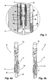
- Fig. 1:
- eine schematisierte perspektivische Ansicht eines zweipoligen Steckverbinders umfassend ein Nullkraftsteckverbindungsteil,
- Fig. 2a, 2b:
- einen Schnitt durch den Steckverbinder der
Figur 1 entlang der Linie A - B in einer ersten Fügestellung (Figur 2a ) sowie in einer parallelen Schnittebene (Figur 2b ), - Fig. 3:
- eine vergrößerte Darstellung des Kontaktierungsbereiches des Steckverbinders der
Figur 2 , - Fig. 4a, 4b:
- eine perspektivische Darstellung des Hülsenkontaktes des Steckverbinders der vorangegangenen Figuren mit seinem Aktivierelement in der Stellung der
Figur 3 (Figur 4a ) sowie in seiner aktivierten Stellung (Figur 4b ), - Fig. 5:
- eine Darstellung entsprechend derjenigen zu
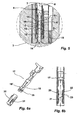
Figur 3 mit den beiden zum Ausbilden des Steckverbinders vorgesehenen Steckverbindungsteilen in ihrer elektrischen kontaktierten Stellung zueinander und - Fig. 6a, b:
- eine perspektivische Ansicht nach Art einer Explosionsdarstellung (
Figur 6a ) sowie eine Längsschnittdarstellung (Figur 6b ) durch ein Hülsenkontakt gemäß einer weiteren Ausgestaltung für ein Nullkraftsteckverbindungsteil. - Ein Steckverbinder 1 umfasst ein zweipoliges Nullkraftsteckverbindungsteil 2, das als Buchsenteil ausgelegt ist sowie ein komplementäres, die Steckerkontakte tragendes Steckverbindungsteil 3. Das Steckverbindungsteil 3 ist bei dem dargestellten Ausführungsbeispiel an die Außenwand eines Steuergerätes, das im Übrigen nicht näher dargestellt ist, angeformt.
- Aus der Rückseite des Nullkraftsteckverbindungsteils 2 sind zwei elektrische Leiter L1, L2 herausgeführt. Die elektrischen Leiter L1, L2 sind mit ihrem vorderen in das Steckverbindungsteil 2 hineinreichenden Ende an jeweils einen Hülsenkontakt angeschlossen, wie dies in der Schnittdarstellung der
Figur 2a erkennbar ist. In dieser Figur ist der Hülsenkontakt mit dem Bezugszeichen 4 gekennzeichnet. Der Hülsenkontakt 4 verfügt über zwei Kontaktlamellen 5, 5', zwischen denen eine Steckerkontaktaufnahme angeordnet ist. In die Steckerkontaktaufnahme ist eine als Messerkontakt ausgebildeter Steckerkontakt 6 des komplementären Steckverbindungsteils 3 eingesetzt. Der Hülsenkontakt 4 verfügt in seinem an die Kontaktlamellen 5, 5' angrenzenden und diese miteinander verbindenden Abschnitt über eine Primärverriegelungsausnehmung 7, in die ein Arretierstift 8 eingreifend angeordnet ist (vgl.Figur 2b ). Der Arretierstift 8 ist Teil eines zum Gehäuse 9 des Steckverbindungsteils 2 gehörenden Einsatzes 10. - Dem Hülsenkontakt 4 zugehörig ist ein als Überfeder konzipiertes Aktivierelement 11, das insbesondere in der vergrößerten Darstellung der
Figur 3 erkennbar ist. Das Aktivierelement 11 ist ein Blechteil und schließt die Kontaktlamellen 5, 5' nach Art eine Käfigs ein. Die Kontaktlamellen 5, 5' sind identisch aufgebaut; aus diesem Grunde ist das Aktivierelement 11 des dargestellten Ausführungsbeispiels ebenfalls bezüglich seiner Überfedereigenschaften bezogen auf die Kontaktlamellen 5, 5' gleichartig an seinen beiden, mit jeweils einer Kontaktlamelle 5 bzw. 5' zusammenwirkenden Seiten aufgebaut. Im Folgenden ist lediglich die Kontaktlamelle 5 und der Abschnitt des Aktivierelementes 11 beschrieben, der der Kontaktlamelle 5 zugeordnet ist. Die diesbezüglichen Ausführungen gelten für die Kontaktlamelle 5' entsprechend. - Die Kontaktlamelle 5 umfasst zwei Kontaktbereiche K1, K2, die jeweils durch einen eine Kontaktsicke tragenden Wulst gebildet sind. Die Kontaktbereiche K1, K2 dienen zum Kontaktieren der Oberfläche des in die Steckkontaktaufnahme des Hülsenkontaktes 4 eingesetzten Steckerkontaktes 6. Der Kontaktbereich K1 befindet sich unter Belassung eines Stellfortsatzes 12 am unteren Ende der Kontaktlamelle 5. Der Kontaktbereich K2 befindet sich mit Abstand zum Kontaktbereich K1. Zwischen den beiden Kontaktbereichen K1, K2 befindet sich eine nach außen gerichtete Ausbauchung 13, gebildet durch zwei zum Scheitel der Ausbauchung 13 geneigt verlaufende Flächen. Das Aktivierelement 11 verfügt an seinem unteren Ende über eine U-förmig ausgebildete Stelllasche 14, die den Stellfortsatz 12 der Kontaktlamelle 5 hintergreift, wie dieses in
Figur 3 erkennbar ist. Die Stelllasche 14 dient zum Abheben der Kontaktlamelle 5 mit ihren Kontaktbereichen K1, K2 von der Oberfläche des Steckerkontaktes 6 in der in denFiguren 2a, 2b und3 gezeigten nicht aktivierten Stellung des Aktivierelementes 11. Zum Abheben des Kontaktbereiches K2 von der Oberfläche des Steckerkontaktes 6 dient eine weitere Stelllasche 15, die eine U-förmige Abkantung des Aktivierelements 11 darstellt und hinter der Kontaktlamelle 5 um diese herumgeführt ist, so dass die Stelllasche 5 zwischen der zu dem Steckerkontakt 6 weisenden Seite der Kontaktlamelle 5 und dem Steckerkontakt 6 angeordnet ist. Die Stelllasche 15 befindet sich in der inFigur 3 gezeigten Stellung des Aktivierelements 11 unmittelbar unter dem Kontaktbereich K2. Sowohl die Stelllasche 14 als auch die Stelllasche 15 sind an ihren zu dem Steckerkontakt 6 weisenden Oberfläche elektrisch isolierend beschichtet, damit eine elektrische Kontaktierung erst bei aktiviertem Aktivierelement 11 zwischen dem Hülsenkontakt 4 und dem Steckerkontakt 6 hergestellt wird. - Das Aktivierelement 11 verfügt über eine Stellnocke 16, die bei dem dargestellten Ausführungsbeispiel der Stelllasche 15 gegenüberliegend an der anderen Oberseite der Kontaktlamelle 5 anliegend angeordnet ist.
- Der in den
Figuren 2a, 2b und3 gezeigten Stellung des Aktivierelements 11 wird der Steckerkontakt 6 in die Steckerkontaktaufnahme des Hülsenkontaktes 4 eingeschoben. Da die Kontaktlamellen 5, 5' in dieser Stellung an der Oberseite des Steckerkontakts 6 nicht anliegen, erfolgt ein Fügen der beiden Steckverbindungsteile 2, 3 ohne besondere Kraftanstrengung. Die zum Fügen notwendige Kraft resultiert insbesondere aus dem Einbringen der Dichtungen in ihren jeweiligen Sitz. Daher wird das Steckverbindungsteil 3 als Nullkraftsteckverbindungsteil bezeichnet. -
Figur 4a zeigt in einer perspektivischen Ansicht den Hülsenkontakt 4 und das einseitig aufgeschnittene, nach Art eines Käfigs ausgebildete Aktivierelement 11. In dieser Darstellung ist auch die Primärverriegelungsausnehmung 7 erkennbar, die in den Hülsenkontakt 4 in seinem an die Kontaktlamellen 5, 5' angrenzenden Abschnitt eingebracht ist. WährendFigur 4a den Hülsenkontakt 4 mit seinem Aktivierelement 11 in der Stellung derFigur 3 zeigt, zeigtFigur 4b die Anordnung derFigur 4a in der aktivierten Stellung des Aktivierelementes 11. - Zum Aufbringen der gewünschten Kontaktkraft zum Kontaktieren des Steckerkontaktes 6 mit den beiden Kontaktlamellen 5, 5' wird das Aktivierelement 11 in Steckrichtung der beiden Steckverbindungsteile 2, 3 gegenüber den Kontaktlamellen 5, 5' verschoben, wie dieses durch den Pfeil der
Figur 4a angedeutet ist. Dieses erfolgt bei dem dargestellten Ausführungsbeispiel im Zuge eines letzten Hubes zum Fügen der beiden Steckverbindungsteile 2, 3. Der in die Primärverriegelungsausnehmung 7 eingreifende Arretierstift 8 dient dabei zum Festhalten der Kontaktbuchse 4, während das Arretierelement 11 gegenüber dem Arretierstift 8 tragenden Einsatz 10 zum Steckverbindungsteil 3 hin weiter verschoben wird. Bei dieser Relativbewegung zwischen dem Arretierelement 11 und den beiden Kontaktlamellen 5, 5' wird die Stellnocke 16 über die die Ausbauchung 13 bildenden geneigten Flächen zum Scheitel der Ausbauchung 13 geschoben. Dabei dienen die geneigten Flächen als Stellflächen. Bei dieser Bewegung werden die Stelllaschen 14,15 von den Kontaktbereichen K1 bzw. K2 wegbewegt, so dass dann durch die über die sich rückseitig an dem Einsatz 10 abstützende Stellnocke 16 auf den Scheitel der Ausbauchung 13 ausgeübte Kraft auf die Kontaktbereiche K1 und K2 zum Herbeiführen der gewünschten Kontaktierung mit der Oberfläche des Steckerkontaktes 6 wirkt (vgl.Figur 5 ). Die mit ihren Kontaktbereichen K1, K2 an der Oberseite des Steckerkontaktes 6 anliegenden Kontaktlamellen 5, 5' sind inFigur 5 dargestellt. Die Neigung der die Stellflächen der Ausbauchung 13 ist dergestalt konzipiert, dass die Stellnocke 16 ohne größere Kraftanstrengung in ihre inFigur 4b gezeigte aktivierte Position des Arretierelementes 11 verschoben werden können. - Ein Lösen des Nullkraftsteckverbindungsteils 2 von dem Steckverbindungsteil 3 erfolgt in umgekehrter Reihenfolge, wobei zunächst das Aktivierelement 11 in seine in
Figur 3 gezeigte Stellung zurückgezogen wird, bevor die Steckerkontakte 6 aus den jeweiligen Kontaktbuchsen 4 durch Abziehen des Steckverbindungsteils 2 von dem Steckverbindungsteil 3 herausgezogen werden. -
Figur 6a zeigt in einer perspektivischen Darstellung einen weiteren Hülsenkontakt 17 zur Verwendung in einem Nullkraftsteckverbindungsteil. Der Hülsenkontakt 17 ist grundsätzlich aufgebaut wie der zu den vorangegangenen Figuren beschriebene Hülsenkontakt 4. Der Hülsenkontakt 17 unterscheidet sich von dem Hülsenkontakt 4 dadurch, dass seine beiden Kontaktlamellen 18, 18' jeweils in ihrem vorderen Bereich eine Öffnung 19 aufweisen. Die Öffnung 19 trennt die beiden Kontaktbereiche der Kontaktlamellen 18, 18' voneinander. Dem Hülsenkontakt 17 ist ein Aktivierelement 20 zugeordnet, das ebenfalls grundsätzlich aufgebaut ist wie das Aktivierelement 11 der vorangegangenen Figuren. Im Unterschied zu dem Aktivierelement 11 verfügt das Aktivierelement 20 über jeweils einen als Lasche ausgebildeten Stellfortsatz 21, der die Öffnungen 19 der Kontaktlamellen 18, 18' durchgreift und somit den hinteren Kontaktbereich der Kontaktlamellen 18, 18' in der nicht aktivierten Stellung des Aktivierelementes 20 von der Oberfläche eines Steckerkontaktes abhebt. Die nicht aktivierte Stellung des Aktivierelementes 20 gegenüber dem Hülsenkontakt 17 ist inFigur 6b gezeigt. Anhand der Kontaktlamelle 18 wird deutlich, dass der Stellfortsatz 21 des Aktivierelements 20 die Kontaktlamelle 18 hintergreift. Der vordere Kontaktbereich der Kontaktlamellen 18 wird durch eine U-förmige vorderseitige Abkantung zur Ausbildung einer Stelllasche, wie diese bereits zu dem Aktivierelement derFiguren 1 - 5 beschrieben ist, herbeigeführt. Durch Längsverschieben des Aktivierelements 20 werden die Kontaktbereiche der Kontaktlamellen 18, 18' an die Oberfläche eines in die Steckerkontaktaufnahme eingesetzten Steckerkontakts zur Anlage gebracht. Die Kontaktkraft resultiert auch bei diesem Ausführungsbeispiel aus jeweils einer rückseitig abgestützten Stellnocke 22, die auf eine Ausbauchung 23 jeder Kontaktlamelle 18 bzw. 18' wirkt. - Die Beschreibung des beanspruchten Nullkraftsteckverbindungsteils macht deutlich, dass durch Vorsehen jeweils eines jeder Kontaktbuchse zugeordneten Aktivierelements grundsätzlich jede Kontaktbuchse individuell aktiviert werden kann. Gleichwohl wird eine Ausgestaltung bevorzugt, bei der sämtliche Aktivierelemente eines Steckverbindungsteils gleichzeitig aktiviert werden. Das beschriebene Nullkraftsteckverbindungsteil eignet sich insbesondere zur Ausbildung von vielpoligen Steckverbindungsteilen und insbesondere solchen, bei der mehrere Polreihen vorgesehen sind. Eine Aktivierung des Aktivierelementes kann sowohl durch den Fügevorgang selbst ausgelöst werden oder durch eine Betätigung eines weiteren Elementes, beispielsweise durch Herbeiführen einer Sekundärverriegelung.
- Von besonderem Vorteil des Gegenstandes der Erfindung ist ferner, dass das Aktivierelement nicht größer ist als herkömmliche Überfedern und somit die Hülsenkontakte mit ihren Arretierelementen grundsätzlich in herkömmliche Buchsengehäuse eingesetzt werden können. Insbesondere werden die die Arretierelemente tragenden Hülsenkontakte in derselben Art und Weise montiert, wie herkömmliche. Dies bedeutet auch, dass die Hülsenkontakte schwimmend in ihrer Gehäusekammer zweckmäßigerweise angeordnet sind, um Toleranzen zwischen den miteinander in Verbindung zu bringenden Steckverbindungsteilen auszugleichen. Die Möglichkeit des Aufbringens einer hohen Kontaktkraft auf die Kontaktbereiche hat zudem den Vorteil, dass es sich bei einer solchen Kontaktierung um eine rein metallische Kontaktierung handelt. Eventuell vorhandene Verunreinigungsschichten auf den miteinander zusammenwirkenden Kontakten können sicher durchdrungen werden. Daher können niedrige Ströme und Spannungen sicher übertragen werden.
-
- 1
- Steckverbinder
- 2
- Nullkraftsteckverbindungsteil
- 3
- Steckverbindungsteil
- 4
- Hülsenkontakt
- 5, 5'
- Kontaktlamelle
- 6
- Steckerkontakt
- 7
- Primärverriegelungsausnehmung
- 8
- Arretierstift
- 9
- Gehäuse
- 10
- Einsatz
- 11
- Aktivierelement
- 12
- Stellfortsatz
- 13
- Ausbauchung
- 14
- Stelllasche
- 15
- Stelllasche
- 16
- Stellnocke
- 17
- Hülsenkontakt
- 18, 18'
- Kontaktlamellen
- 19
- Öffnungen
- 20
- Aktivierelement
- 21
- Stellfortsatz
- 22
- Stellnocke
- 23
- Ausbauchung
- K1, K2
- Kontaktbereich
- L1, L2
- Leiter
Claims (13)
- Elektrisches Nullkraftsteckverbindungsteil (2), das ein oder mehrere, jeweils zumindest einen Kontaktbereich (K1, K2) aufweisende Hülsenkontakte (4, 17), ausgebildet jeweils zur Aufnahme eines komplementären elektrischen Steckerkontakts (6) aufweist, wobei dem/den Hülsenkontakt(en) (4, 17) ein gegenüber diesem/diesen verstellbares Aktivierelement (11, 20) zugeordnet ist, durch das in seiner aktivierten Stellung zum Kontaktieren jeweils eines in jeweils einen Hülsenkontakt (4, 17) eingesetzten Steckerkontakts (6) die Kontaktkraft auf den/die Kontaktbereich(e) (K1, K2) des/der Hülsenkontakt(s/e) (4, 17) aufgebracht wird, dadurch gekennzeichnet, dass jedem Hülsenkontakt (4, 17) jeweils ein als Überfeder ausgeführtes Aktivierelement (11, 20) individuell zugeordnet ist.
- Nullkraftsteckverbindungsteil nach Anspruch 1, dadurch gekennzeichnet, dass die Kontaktbereiche (K1, K2) der Hülsenkontakte (4, 17) in der nicht aktivierten Stellung der Aktivierelemente (11, 20) von der Kontaktoberfläche eines in einen Hülsenkontakt (4, 17) eingesteckten Steckerkontakts (6) abgehoben sind.
- Nullkraftsteckverbindungsteil nach Anspruch 2, dadurch gekennzeichnet, dass die Aktivierelemente (11, 20) eine jedem Kontaktbereich (K1, K2) des Hülsenkontaktes (4, 17) zugeordnete Stelllasche (14, 15; 21) aufweisen, durch die in der nicht aktivierten Stellung des Aktivierelements (11, 20) der bzw. die Kontaktbereiche (K1, K2) von der Kontaktoberfläche eines in einen Hülsenkontakt (4, 17) eingesteckten Steckerkontakts abgehoben sind.
- Nullkraftsteckverbindungsteil nach Anspruch 3, dadurch gekennzeichnet, dass die Stelllaschen (14, 15; 21) zumindest an ihrer in die Steckeraufnahme eines Hülsenkontaktes (4, 17) weisenden Seite elektrisch isoliert sind.
- Nullkraftsteckverbindungsteil nach einem der Ansprüche 1 bis 4, dadurch gekennzeichnet, dass die Hülsenkontakte (4, 17) zwei einander bezüglich der Längsachse eines Hülsenkontakts (4, 17) gegenüberliegende, jeweils zumindest einen als Kontaktbereich (K1, K2) vorgesehenen Kontaktpunkt oder Kontaktwulst aufweisende, durch ein als Käfig ausgebildetes Aktivierelement (11, 20) verbundene Kontaktlamellen (5, 5'; 18, 18') aufweisen.
- Nullkraftsteckverbindungsteil nach Anspruch 5, dadurch gekennzeichnet, dass jede Kontaktlamelle (5, 5'; 18, 18') im Bereich ihres freien, zur Mündung der Steckeraufnahme weisenden Endes unter Belassung eines Stellfortsatzes (12) einen ersten Kontaktbereich (K1) und einen zweiten mit Abstand dazu angeordneten Kontaktbereich (K2) aufweist und dass das Aktivierelement (11, 20) vorderseitig zur Ausbildung einer dem ersten Kontaktbereich (K1) zugeordneten, den Stellfortsatz (12) hintergreifenden Stelllasche (14) U-förmig ausgebildet ist.
- Nullkraftsteckverbindungsteil nach Anspruch 6, dadurch gekennzeichnet, dass das Aktivierelement (11) eine zweite, zeitlich angeformte U-förmig ausgebildete, dem zweiten Kontaktbereich (K2) zugeordnete Stelllasche (15) aufweist.
- Nullkraftsteckverbindungsteil nach Anspruch 6, dadurch gekennzeichnet, dass die Kontaktlamellen (18, 18') aus Richtung der Mündung der Steckeraufnahme vor ihrem zweiten Kontaktbereich eine Öffnung (19) aufweisen, durch die eine Verkröpfung des Aktivierelements (20) als Stelllasche (12) für den zweiten Kontaktbereich durchgreift.
- Nullkraftsteckverbindungsteil nach einem der Ansprüche 6 bis 8, dadurch gekennzeichnet, dass zwischen den beiden Kontaktbereichen (K1, K2) einer Kontaktlamelle (5, 5'; 18, 18') diese eine zum Aktivierelement (11, 20) weisende Ausbauchung (13) aufweist und das Aktivierelement (11, 20) eine Stellnocke (16, 22) trägt, die in der aktivierten Stellung des Aktivierelements (11, 20) die Kontaktkraft über die Ausbauchung (13) in die Kontaktlamelle (5, 5'; 18, 18') einleitend angeordnet ist.
- Nullkraftsteckverbindungsteil nach einem der Ansprüche 5 bis 9, dadurch gekennzeichnet, dass das Aktivierelement (11, 20) in seiner aktivierten Stellung auf beide gleichermaßen ausgebildete Kontaktlamellen (5, 5'; 18, 18') eines Hülsenkontakts (4, 17) zur Bereitstellung der Kontaktkraft wirkt.
- Nullkraftsteckverbindungsteil nach einem der Ansprüche 1 bis 10, dadurch gekennzeichnet, dass der Hülsenkontakt (4) gegenüber dem Aktivierelement (11) und seinem Buchsengehäuse (9) in Steckrichtung zum Kontaktieren eines Steckerkontakts (6) längsverschiebbar ist und das Buchsengehäuse (9) einen Arretierstift (8) aufweist, der an einem Anschlag (7) des Hülsenkontakts (4) zur Anlage gelangt, wenn der Hülsenkontakt primärverriegelt in ein Buchsengehäuse (9) eingesetzt ist, und durch den bei einer ausgeführten Bewegung zum Verbinden des Steckverbindungsteils (2) mit einem die Steckerkontakte (6) tragenden weiteren Steckverbindungsteil (3) das Aktivierelement (11) relativ gegenüber dem Hülsenkontakt (4) zum Anlegen der Kontaktkraft auf den Hülsenkontakt (4) bewegt wird.
- Nullkraftsteckverbindungsteil nach Anspruch 11, dadurch gekennzeichnet, dass bei einer Einsteckbewegung zum Verbinden des Steckverbindungsteils (2) mit einem die Steckerkontakte (6) tragenden weiteren Steckverbindungsteil (3) das Aktivierelement (11) im Zuge der Einsteckbewegung zum Verbinden der beiden Steckverbindungsteile (2, 3) miteinander relativ gegenüber dem Hülsenkontakt (4) zum Anlegen der Kontaktkraft auf den Hülsenkontakt (4) verschoben wird.
- Nullkraftsteckverbindungsteil nach Anspruch 11, dadurch gekennzeichnet, dass das Aktivierelement an eine Sekundärverriegelung angeschlossen ist, bei deren Betätigung das Aktivierelement relativ zum Anlegen der Kontaktkraft auf den Hülsenkontakt bewegt wird.
Applications Claiming Priority (2)
| Application Number | Priority Date | Filing Date | Title |
|---|---|---|---|
| DE102004015344A DE102004015344A1 (de) | 2004-03-30 | 2004-03-30 | Elektrisches Nullkraftsteckverbindungsteil |
| PCT/EP2005/003222 WO2005096449A1 (de) | 2004-03-30 | 2005-03-26 | Elektrisches nullkraftsteckverbindungsteil |
Publications (2)
| Publication Number | Publication Date |
|---|---|
| EP1730819A1 EP1730819A1 (de) | 2006-12-13 |
| EP1730819B1 true EP1730819B1 (de) | 2011-09-28 |
Family
ID=34962683
Family Applications (1)
| Application Number | Title | Priority Date | Filing Date |
|---|---|---|---|
| EP05716394A Active EP1730819B1 (de) | 2004-03-30 | 2005-03-26 | Elektrisches nullkraftsteckverbindungsteil |
Country Status (7)
| Country | Link |
|---|---|
| US (1) | US7291030B2 (de) |
| EP (1) | EP1730819B1 (de) |
| JP (1) | JP4809827B2 (de) |
| AT (1) | ATE526707T1 (de) |
| BR (1) | BRPI0508757B1 (de) |
| DE (1) | DE102004015344A1 (de) |
| WO (1) | WO2005096449A1 (de) |
Families Citing this family (16)
| Publication number | Priority date | Publication date | Assignee | Title |
|---|---|---|---|---|
| DE102005040952A1 (de) * | 2005-08-30 | 2007-03-08 | Kostal Kontakt Systeme Gmbh | Elektrischer Nullkraftsteckverbinder |
| DE102006013347B4 (de) * | 2006-03-23 | 2022-12-22 | Kostal Kontakt Systeme Gmbh | Steckverbinderanordnung |
| DE102009036807B4 (de) | 2009-08-10 | 2011-09-01 | Tyco Electronics Amp Gmbh | Elektrische Steckverbinderanordnung mit verringerter Steckkraft |
| DE102009057688A1 (de) * | 2009-12-09 | 2011-06-16 | Kostal Kontakt Systeme Gmbh | Elektrischer Nullkraftsteckverbinder |
| JP5299262B2 (ja) * | 2009-12-24 | 2013-09-25 | 日立電線株式会社 | 接続構造 |
| DE102010001168A1 (de) * | 2010-01-25 | 2011-07-28 | Ford Global Technologies, LLC, Mich. | Steckverbinder und Verfahren zur Herstellung einer Steckverbindung |
| DE102010014980A1 (de) * | 2010-04-14 | 2011-10-20 | Pfisterer Kontaktsysteme Gmbh | Elektrisches Steckverbindungselement und Steckverbindungsteil mit mehreren Steckverbindungselementen |
| JP5673457B2 (ja) * | 2011-01-19 | 2015-02-18 | 日立金属株式会社 | コネクタ |
| DE102012002145A1 (de) | 2012-02-04 | 2013-08-08 | Kostal Kontakt Systeme Gmbh | Hülsenkontakt für einen elektrischen Nullkraftsteckverbinder |
| DE102012101709B4 (de) | 2012-03-01 | 2015-05-28 | Phoenix Contact Gmbh & Co. Kg | Steckverbinder |
| DE102012015568B4 (de) * | 2012-08-08 | 2018-12-20 | Auto-Kabel Management Gmbh | Steckverbinder |
| DE102012020767A1 (de) * | 2012-10-23 | 2014-04-24 | Kostal Kontakt Systeme Gmbh | Elektrischer Nullkraftsteckverbinder |
| US8926360B2 (en) | 2013-01-17 | 2015-01-06 | Cooper Technologies Company | Active cooling of electrical connectors |
| US9093764B2 (en) | 2013-01-17 | 2015-07-28 | Cooper Technologies Company | Electrical connectors with force increase features |
| US20140348581A1 (en) * | 2013-05-24 | 2014-11-27 | Soucy International Inc. | Mounting System for a Vehicle and Method of Using the Same |
| DE102019133032A1 (de) | 2019-12-04 | 2021-08-12 | Te Connectivity Germany Gmbh | Elektrische Kleinkraft-Kontakteinrichtung sowie elektrischer Kleinkraft-Verbinder |
Family Cites Families (15)
| Publication number | Priority date | Publication date | Assignee | Title |
|---|---|---|---|---|
| US3491329A (en) | 1967-05-29 | 1970-01-20 | Gerald W Lecocq | Releasable electrical terminal |
| US3710304A (en) | 1971-05-05 | 1973-01-09 | J Warner | Locking electric plug |
| FR2239025B1 (de) * | 1973-07-25 | 1982-07-02 | Souriau & Cie | |
| US4023881A (en) * | 1975-09-12 | 1977-05-17 | Souriau Et Cie | Connectors |
| JPH0633669Y2 (ja) * | 1988-02-02 | 1994-08-31 | 富士通株式会社 | カード用コネクタ |
| JPH02199780A (ja) * | 1989-01-30 | 1990-08-08 | Yazaki Corp | 低挿入力端子 |
| DE8907845U1 (de) * | 1989-06-27 | 1989-08-24 | Siemens AG, 1000 Berlin und 8000 München | Andruckstellverbinder |
| JPH0521109A (ja) * | 1991-07-12 | 1993-01-29 | Taisei Corp | ロツク型電源コンセント |
| JPH0562740A (ja) * | 1991-08-29 | 1993-03-12 | Fujikura Ltd | 低挿入力コネクタ |
| JPH0545964U (ja) * | 1991-11-14 | 1993-06-18 | 矢崎総業株式会社 | 低挿入力コネクタ |
| DE4409229A1 (de) * | 1994-03-18 | 1995-09-21 | Bosch Gmbh Robert | Elektrische Verbinderanordnung |
| DE19742400C2 (de) * | 1997-09-25 | 2002-01-10 | Tyco Electronics Logistics Ag | Leiterplatten-Nullkraftsteckverbinder |
| US6083023A (en) * | 1998-11-03 | 2000-07-04 | Yazaki North America, Inc. | Cam actuated low insertion force electrical connector |
| JP2000260521A (ja) * | 1999-03-09 | 2000-09-22 | Yazaki Corp | コネクタ |
| DE102005040952A1 (de) * | 2005-08-30 | 2007-03-08 | Kostal Kontakt Systeme Gmbh | Elektrischer Nullkraftsteckverbinder |
-
2004
- 2004-03-30 DE DE102004015344A patent/DE102004015344A1/de not_active Withdrawn
-
2005
- 2005-03-26 JP JP2007505473A patent/JP4809827B2/ja not_active Expired - Fee Related
- 2005-03-26 AT AT05716394T patent/ATE526707T1/de active
- 2005-03-26 WO PCT/EP2005/003222 patent/WO2005096449A1/de active Application Filing
- 2005-03-26 BR BRPI0508757-0A patent/BRPI0508757B1/pt not_active IP Right Cessation
- 2005-03-26 EP EP05716394A patent/EP1730819B1/de active Active
-
2006
- 2006-09-25 US US11/527,049 patent/US7291030B2/en not_active Expired - Fee Related
Also Published As
| Publication number | Publication date |
|---|---|
| BRPI0508757B1 (pt) | 2018-05-02 |
| US7291030B2 (en) | 2007-11-06 |
| WO2005096449A1 (de) | 2005-10-13 |
| US20070099508A1 (en) | 2007-05-03 |
| EP1730819A1 (de) | 2006-12-13 |
| JP4809827B2 (ja) | 2011-11-09 |
| ATE526707T1 (de) | 2011-10-15 |
| BRPI0508757A (pt) | 2007-08-28 |
| JP2008535146A (ja) | 2008-08-28 |
| DE102004015344A1 (de) | 2005-10-20 |
Similar Documents
| Publication | Publication Date | Title |
|---|---|---|
| EP1730819B1 (de) | Elektrisches nullkraftsteckverbindungsteil | |
| EP3298659B1 (de) | Leiteranschlussklemme | |
| EP1777720B1 (de) | Elektrisches Bauteil, insbesondere Relaisfassung, mit Federklemmen und Verfahren zu seiner Herstellung | |
| DE102016113974B4 (de) | Anschlusseinrichtung, Betätiger für die Anschlusseinrichtung und Verfahren zum Entriegeln der Anschlusseinrichtung | |
| EP2810341B1 (de) | Hülsenkontakt für einen elektrischen nullkraftsteckverbinder | |
| DE102010008536B4 (de) | Elektrische Anschlusseinrichtung | |
| WO2017081197A1 (de) | Steckkontakt | |
| WO2019192911A1 (de) | Elektrischer steckverbinder, modulares system und verfahren zur bereitstellung eines steckverbinders | |
| EP3446367B1 (de) | Steckkontakt | |
| DE202014010621U1 (de) | Steckverbinder | |
| DE202016008409U1 (de) | Betätiger für eine Anschlusseinrichtung für elektrische Leiter | |
| DE19702373A1 (de) | Elektrischer Steckverbinder mit einer Kurzschlußfeder und Kurzschlußfeder | |
| DE102015113734A1 (de) | Steckverbinder | |
| DE102021104504A1 (de) | Anschlussanordnung, Anschlussklemme und elektronisches Gerät | |
| DE102016116091A1 (de) | Elektrischer Anschlussverbinder mit Berührungsschutz | |
| DE202016008242U1 (de) | Steckkontakt | |
| DE69410027T2 (de) | Vorrichtung und Verfahren zum mechanischen und elektrischen Verbinden von metallischen Kontaktteilen in einem Gehäuse | |
| EP3849018B1 (de) | Leiteranschlussklemme | |
| DE202014010620U1 (de) | Steckverbinder | |
| DE10216915A1 (de) | Flexfolienkontaktanordnung | |
| DE10320460B4 (de) | Elektrische Steckverbindung | |
| DE3447654A1 (de) | Elektrischer stecker | |
| EP3782235A1 (de) | Direktsteckverbinder | |
| DE102008014731B4 (de) | Steckverbinder | |
| DE212019000423U1 (de) | Anschlussvorrichtung für elektrische Leiter |
Legal Events
| Date | Code | Title | Description |
|---|---|---|---|
| PUAI | Public reference made under article 153(3) epc to a published international application that has entered the european phase |
Free format text: ORIGINAL CODE: 0009012 |
|
| 17P | Request for examination filed |
Effective date: 20060906 |
|
| AK | Designated contracting states |
Kind code of ref document: A1 Designated state(s): AT BE BG CH CY CZ DE DK EE ES FI FR GB GR HU IE IS IT LI LT LU MC NL PL PT RO SE SI SK TR |
|
| DAX | Request for extension of the european patent (deleted) | ||
| 17Q | First examination report despatched |
Effective date: 20091030 |
|
| GRAP | Despatch of communication of intention to grant a patent |
Free format text: ORIGINAL CODE: EPIDOSNIGR1 |
|
| GRAS | Grant fee paid |
Free format text: ORIGINAL CODE: EPIDOSNIGR3 |
|
| GRAA | (expected) grant |
Free format text: ORIGINAL CODE: 0009210 |
|
| AK | Designated contracting states |
Kind code of ref document: B1 Designated state(s): AT BE BG CH CY CZ DE DK EE ES FI FR GB GR HU IE IS IT LI LT LU MC NL PL PT RO SE SI SK TR |
|
| REG | Reference to a national code |
Ref country code: GB Ref legal event code: FG4D Free format text: NOT ENGLISH |
|
| REG | Reference to a national code |
Ref country code: CH Ref legal event code: EP |
|
| REG | Reference to a national code |
Ref country code: IE Ref legal event code: FG4D |
|
| REG | Reference to a national code |
Ref country code: DE Ref legal event code: R096 Ref document number: 502005011928 Country of ref document: DE Effective date: 20111222 |
|
| REG | Reference to a national code |
Ref country code: NL Ref legal event code: VDEP Effective date: 20110928 |
|
| PG25 | Lapsed in a contracting state [announced via postgrant information from national office to epo] |
Ref country code: LT Free format text: LAPSE BECAUSE OF FAILURE TO SUBMIT A TRANSLATION OF THE DESCRIPTION OR TO PAY THE FEE WITHIN THE PRESCRIBED TIME-LIMIT Effective date: 20110928 Ref country code: SE Free format text: LAPSE BECAUSE OF FAILURE TO SUBMIT A TRANSLATION OF THE DESCRIPTION OR TO PAY THE FEE WITHIN THE PRESCRIBED TIME-LIMIT Effective date: 20110928 Ref country code: FI Free format text: LAPSE BECAUSE OF FAILURE TO SUBMIT A TRANSLATION OF THE DESCRIPTION OR TO PAY THE FEE WITHIN THE PRESCRIBED TIME-LIMIT Effective date: 20110928 |
|
| LTIE | Lt: invalidation of european patent or patent extension |
Effective date: 20110928 |
|
| PG25 | Lapsed in a contracting state [announced via postgrant information from national office to epo] |
Ref country code: CY Free format text: LAPSE BECAUSE OF FAILURE TO SUBMIT A TRANSLATION OF THE DESCRIPTION OR TO PAY THE FEE WITHIN THE PRESCRIBED TIME-LIMIT Effective date: 20110928 Ref country code: GR Free format text: LAPSE BECAUSE OF FAILURE TO SUBMIT A TRANSLATION OF THE DESCRIPTION OR TO PAY THE FEE WITHIN THE PRESCRIBED TIME-LIMIT Effective date: 20111229 Ref country code: SI Free format text: LAPSE BECAUSE OF FAILURE TO SUBMIT A TRANSLATION OF THE DESCRIPTION OR TO PAY THE FEE WITHIN THE PRESCRIBED TIME-LIMIT Effective date: 20110928 |
|
| REG | Reference to a national code |
Ref country code: IE Ref legal event code: FD4D |
|
| PG25 | Lapsed in a contracting state [announced via postgrant information from national office to epo] |
Ref country code: SK Free format text: LAPSE BECAUSE OF FAILURE TO SUBMIT A TRANSLATION OF THE DESCRIPTION OR TO PAY THE FEE WITHIN THE PRESCRIBED TIME-LIMIT Effective date: 20110928 Ref country code: CZ Free format text: LAPSE BECAUSE OF FAILURE TO SUBMIT A TRANSLATION OF THE DESCRIPTION OR TO PAY THE FEE WITHIN THE PRESCRIBED TIME-LIMIT Effective date: 20110928 Ref country code: IS Free format text: LAPSE BECAUSE OF FAILURE TO SUBMIT A TRANSLATION OF THE DESCRIPTION OR TO PAY THE FEE WITHIN THE PRESCRIBED TIME-LIMIT Effective date: 20120128 |
|
| PG25 | Lapsed in a contracting state [announced via postgrant information from national office to epo] |
Ref country code: EE Free format text: LAPSE BECAUSE OF FAILURE TO SUBMIT A TRANSLATION OF THE DESCRIPTION OR TO PAY THE FEE WITHIN THE PRESCRIBED TIME-LIMIT Effective date: 20110928 Ref country code: RO Free format text: LAPSE BECAUSE OF FAILURE TO SUBMIT A TRANSLATION OF THE DESCRIPTION OR TO PAY THE FEE WITHIN THE PRESCRIBED TIME-LIMIT Effective date: 20110928 Ref country code: IT Free format text: LAPSE BECAUSE OF FAILURE TO SUBMIT A TRANSLATION OF THE DESCRIPTION OR TO PAY THE FEE WITHIN THE PRESCRIBED TIME-LIMIT Effective date: 20110928 Ref country code: NL Free format text: LAPSE BECAUSE OF FAILURE TO SUBMIT A TRANSLATION OF THE DESCRIPTION OR TO PAY THE FEE WITHIN THE PRESCRIBED TIME-LIMIT Effective date: 20110928 Ref country code: PT Free format text: LAPSE BECAUSE OF FAILURE TO SUBMIT A TRANSLATION OF THE DESCRIPTION OR TO PAY THE FEE WITHIN THE PRESCRIBED TIME-LIMIT Effective date: 20120130 |
|
| PG25 | Lapsed in a contracting state [announced via postgrant information from national office to epo] |
Ref country code: IE Free format text: LAPSE BECAUSE OF FAILURE TO SUBMIT A TRANSLATION OF THE DESCRIPTION OR TO PAY THE FEE WITHIN THE PRESCRIBED TIME-LIMIT Effective date: 20110928 Ref country code: DK Free format text: LAPSE BECAUSE OF FAILURE TO SUBMIT A TRANSLATION OF THE DESCRIPTION OR TO PAY THE FEE WITHIN THE PRESCRIBED TIME-LIMIT Effective date: 20110928 |
|
| PLBE | No opposition filed within time limit |
Free format text: ORIGINAL CODE: 0009261 |
|
| STAA | Information on the status of an ep patent application or granted ep patent |
Free format text: STATUS: NO OPPOSITION FILED WITHIN TIME LIMIT |
|
| PG25 | Lapsed in a contracting state [announced via postgrant information from national office to epo] |
Ref country code: PL Free format text: LAPSE BECAUSE OF FAILURE TO SUBMIT A TRANSLATION OF THE DESCRIPTION OR TO PAY THE FEE WITHIN THE PRESCRIBED TIME-LIMIT Effective date: 20110928 |
|
| 26N | No opposition filed |
Effective date: 20120629 |
|
| BERE | Be: lapsed |
Owner name: KOSTAL KONTAKT SYSTEME G.M.B.H. Effective date: 20120331 |
|
| REG | Reference to a national code |
Ref country code: DE Ref legal event code: R097 Ref document number: 502005011928 Country of ref document: DE Effective date: 20120629 |
|
| PG25 | Lapsed in a contracting state [announced via postgrant information from national office to epo] |
Ref country code: MC Free format text: LAPSE BECAUSE OF NON-PAYMENT OF DUE FEES Effective date: 20120331 |
|
| REG | Reference to a national code |
Ref country code: CH Ref legal event code: PL |
|
| PG25 | Lapsed in a contracting state [announced via postgrant information from national office to epo] |
Ref country code: CH Free format text: LAPSE BECAUSE OF NON-PAYMENT OF DUE FEES Effective date: 20120331 Ref country code: LI Free format text: LAPSE BECAUSE OF NON-PAYMENT OF DUE FEES Effective date: 20120331 Ref country code: BE Free format text: LAPSE BECAUSE OF NON-PAYMENT OF DUE FEES Effective date: 20120331 |
|
| PG25 | Lapsed in a contracting state [announced via postgrant information from national office to epo] |
Ref country code: ES Free format text: LAPSE BECAUSE OF FAILURE TO SUBMIT A TRANSLATION OF THE DESCRIPTION OR TO PAY THE FEE WITHIN THE PRESCRIBED TIME-LIMIT Effective date: 20120108 |
|
| REG | Reference to a national code |
Ref country code: AT Ref legal event code: MM01 Ref document number: 526707 Country of ref document: AT Kind code of ref document: T Effective date: 20120326 |
|
| PG25 | Lapsed in a contracting state [announced via postgrant information from national office to epo] |
Ref country code: BG Free format text: LAPSE BECAUSE OF FAILURE TO SUBMIT A TRANSLATION OF THE DESCRIPTION OR TO PAY THE FEE WITHIN THE PRESCRIBED TIME-LIMIT Effective date: 20111228 |
|
| PG25 | Lapsed in a contracting state [announced via postgrant information from national office to epo] |
Ref country code: AT Free format text: LAPSE BECAUSE OF NON-PAYMENT OF DUE FEES Effective date: 20120326 |
|
| PG25 | Lapsed in a contracting state [announced via postgrant information from national office to epo] |
Ref country code: TR Free format text: LAPSE BECAUSE OF FAILURE TO SUBMIT A TRANSLATION OF THE DESCRIPTION OR TO PAY THE FEE WITHIN THE PRESCRIBED TIME-LIMIT Effective date: 20110928 |
|
| PG25 | Lapsed in a contracting state [announced via postgrant information from national office to epo] |
Ref country code: LU Free format text: LAPSE BECAUSE OF NON-PAYMENT OF DUE FEES Effective date: 20120326 |
|
| PG25 | Lapsed in a contracting state [announced via postgrant information from national office to epo] |
Ref country code: HU Free format text: LAPSE BECAUSE OF FAILURE TO SUBMIT A TRANSLATION OF THE DESCRIPTION OR TO PAY THE FEE WITHIN THE PRESCRIBED TIME-LIMIT Effective date: 20050326 |
|
| REG | Reference to a national code |
Ref country code: FR Ref legal event code: PLFP Year of fee payment: 12 |
|
| REG | Reference to a national code |
Ref country code: FR Ref legal event code: PLFP Year of fee payment: 13 |
|
| REG | Reference to a national code |
Ref country code: FR Ref legal event code: PLFP Year of fee payment: 14 |
|
| REG | Reference to a national code |
Ref country code: DE Ref legal event code: R084 Ref document number: 502005011928 Country of ref document: DE |
|
| REG | Reference to a national code |
Ref country code: DE Ref legal event code: R081 Ref document number: 502005011928 Country of ref document: DE Owner name: KOSTAL KONTAKT SYSTEME GMBH & CO. KG, DE Free format text: FORMER OWNER: KOSTAL KONTAKT SYSTEME GMBH, 58513 LUEDENSCHEID, DE |
|
| PGFP | Annual fee paid to national office [announced via postgrant information from national office to epo] |
Ref country code: DE Payment date: 20240305 Year of fee payment: 20 Ref country code: GB Payment date: 20240327 Year of fee payment: 20 |
|
| PGFP | Annual fee paid to national office [announced via postgrant information from national office to epo] |
Ref country code: FR Payment date: 20240329 Year of fee payment: 20 |