EP1728956B2 - Gegen ein Aushebeln von aussen sichernder Beschlag für eine Hebe-Schiebe-Tür - Google Patents
Gegen ein Aushebeln von aussen sichernder Beschlag für eine Hebe-Schiebe-Tür Download PDFInfo
- Publication number
- EP1728956B2 EP1728956B2 EP05104634.0A EP05104634A EP1728956B2 EP 1728956 B2 EP1728956 B2 EP 1728956B2 EP 05104634 A EP05104634 A EP 05104634A EP 1728956 B2 EP1728956 B2 EP 1728956B2
- Authority
- EP
- European Patent Office
- Prior art keywords
- locking element
- bogie
- locking
- connecting rod
- wing
- Prior art date
- Legal status (The legal status is an assumption and is not a legal conclusion. Google has not performed a legal analysis and makes no representation as to the accuracy of the status listed.)
- Expired - Lifetime
Links
Images


Classifications
-
- E—FIXED CONSTRUCTIONS
- E05—LOCKS; KEYS; WINDOW OR DOOR FITTINGS; SAFES
- E05D—HINGES OR SUSPENSION DEVICES FOR DOORS, WINDOWS OR WINGS
- E05D15/00—Suspension arrangements for wings
- E05D15/56—Suspension arrangements for wings with successive different movements
- E05D15/565—Suspension arrangements for wings with successive different movements for raising wings before sliding
-
- E—FIXED CONSTRUCTIONS
- E05—LOCKS; KEYS; WINDOW OR DOOR FITTINGS; SAFES
- E05Y—INDEXING SCHEME ASSOCIATED WITH SUBCLASSES E05D AND E05F, RELATING TO CONSTRUCTION ELEMENTS, ELECTRIC CONTROL, POWER SUPPLY, POWER SIGNAL OR TRANSMISSION, USER INTERFACES, MOUNTING OR COUPLING, DETAILS, ACCESSORIES, AUXILIARY OPERATIONS NOT OTHERWISE PROVIDED FOR, APPLICATION THEREOF
- E05Y2201/00—Constructional elements; Accessories therefor
- E05Y2201/20—Brakes; Disengaging means; Holders; Stops; Valves; Accessories therefor
- E05Y2201/218—Holders
- E05Y2201/22—Locks
-
- E—FIXED CONSTRUCTIONS
- E05—LOCKS; KEYS; WINDOW OR DOOR FITTINGS; SAFES
- E05Y—INDEXING SCHEME ASSOCIATED WITH SUBCLASSES E05D AND E05F, RELATING TO CONSTRUCTION ELEMENTS, ELECTRIC CONTROL, POWER SUPPLY, POWER SIGNAL OR TRANSMISSION, USER INTERFACES, MOUNTING OR COUPLING, DETAILS, ACCESSORIES, AUXILIARY OPERATIONS NOT OTHERWISE PROVIDED FOR, APPLICATION THEREOF
- E05Y2800/00—Details, accessories and auxiliary operations not otherwise provided for
-
- E—FIXED CONSTRUCTIONS
- E05—LOCKS; KEYS; WINDOW OR DOOR FITTINGS; SAFES
- E05Y—INDEXING SCHEME ASSOCIATED WITH SUBCLASSES E05D AND E05F, RELATING TO CONSTRUCTION ELEMENTS, ELECTRIC CONTROL, POWER SUPPLY, POWER SIGNAL OR TRANSMISSION, USER INTERFACES, MOUNTING OR COUPLING, DETAILS, ACCESSORIES, AUXILIARY OPERATIONS NOT OTHERWISE PROVIDED FOR, APPLICATION THEREOF
- E05Y2900/00—Application of doors, windows, wings or fittings thereof
- E05Y2900/10—Application of doors, windows, wings or fittings thereof for buildings or parts thereof
- E05Y2900/13—Type of wing
- E05Y2900/132—Doors
Definitions
- the invention relates to a fitting for a lift-slide wing, which is associated with an anti-burglary against an attempted from the outside wing levering.
- door wings are addressed as wings, which can be formed in a lift-slide door (with fixed frame and fixed wing).
- Out DE-U 299 20 094 (Siegenia ) is an intervention above the sliding door to the local FIG. 3 provided, cf. there FIGS. 1 and 3 and related description page 9, last paragraph.
- This arrangement is not coupled via both carriages, but mounted alone on the vertical bar on which the operating handle is arranged.
- Out EP-A 1 312 743 (GU ) is a safety device lying on the upper rail accessible to the skilled person in the local FIG. 2 and 1 can be recognized in two operational positions.
- the backup should be done on the remote from the operating lever and the gearbox of the fitting on the first vertical spar vertical spar of the wing.
- an additional movement-deflection device is assigned, which is associated with a locking element, which is formed and can be stored on the wing stationary so that it in the closed position of the wing the spatially arranged recording engages and this even engages under.
- the wing is thus secured in the region of the opposite side of the transmission vertical against both levers and against breaking in the direction of displacement.
- the locking elements which moved linearly and pivotally, are movably guided close to the second carriage on a kind of bearing block.
- a motion-deflection is provided, which converts the longitudinal movement, which starts from the vertical push rod and continues on the lower horizontal bar after the first corner deflection, in the locking movement.
- This transfer device is not raised or higher than the height range of the rear carriage, so it is in the mounted state still in the rebate between the lower edge of the wing and the running rail.
- This deflection device does not extend significantly beyond the second carriage in the vertical direction, the second carriage being understood as a complete functional unit comprising both rollers on the chassis and the holding and control device which can be mounted on the lower end side along which the chassis is movable while being relatively relocated in height.
- the longitudinal movement is also caused by the vertical push rod, so transmits over the carriage chassis on the transfer device, which is located near the rear carriage in the horizontal direction and in the height direction does not extend beyond it substantially.
- the distance between the two carriages is substantially greater than the distance of the deflection of the second carriage, which is closer to the vertical end face of the spar, which is removed from the actuating spar, which actuating beam is the one who carries the gear and the hand lever.
- a sufficiently deep engagement width is circumscribed in the linear movement of the locking element so that it is sufficiently dimensioned for blocking a levering. How large the implementation and the Umsetzson of longitudinal movement in vertical thrust movement of the linearly moving locking element is determined in accordance with the free spaces between the upper edge of the wing and the upper door frame.
- the engagement should extend at least so far that raising the wing to the inner end face of the upper Festholms not yet leads to a release of the locking element from the engagement receptacle of the track rail. In the embodiment with a pivoting engagement this depth of engagement is not to be measured, but the Festkrallung carried by the pivoting movement with a hook-shaped end of the at least one locking element (claim 1).
- an increase can actively be locked by touching concerns on the underside of the rail, not by sufficiently deep engagement width, which can be named in comparison rather than passive blocking.
- the settling of the counterforce is carried out at an attachment of the engagement receptacle (s) in the running rail or on both sides next to the track of the running rail on the environment of the at least one engagement receptacle.
- the longitudinal movement and the transverse movement of the locking element is to be carried out that the longitudinal movement parallel to the bottom (the lower end face) of the movable wing, and perpendicular to a transverse locking movement is applied, which is either pivoting or ausschiebend.
- a transverse direction but is also that direction perpendicular to the above to understand, which symbolically symbolizes the distance of two juxtaposed, preferably congruent formed locking elements.
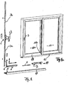
- FIG. 1a The sash and the fixed frame parts of a lift-slide door are well known, so an indication of FIG. 1a enough.
- the space-fixed 13 and the movable (wing) door part 12 the sash with actuating handle or lever 3 for the built-in gear and the stationary slide rail 10 shown, with the sliding sash is in its closed position.
- the lower spar of the wing is 14. Its lower end face is 12a, to which the carriages are mounted 5.7.
- this fitting is associated with a wing 12, which - as in FIG. 1a - Is moved from left to right from the closed to the open position after he has been raised by operating the handle or lever 3 first, before he can be moved to the side in front of the fixed part 13 of the door.
- the through hole ie in FIG. 1 from the left side.
- Right is the "rear end” and the "rear lower corner” 14b.
- the fitting 1 is formed in such a way that upon pivoting of the lever 3 in the seaming groove and behind the cover rail 3b at least one push rod 3a vertically is moved up or down.
- the downwardly directed push rod 3a is coupled at its lower end with a corner 4 at 6, wherein the corner drive is associated with a first carriage 5, in turn, via a long connecting rod 8 with a second carriage 7 near the other, the rear lower corner of the Wing 12 is coupled in terms of actuation.
- a lifting movement is first triggered on the two carriages 5 and 7, after which with the help of the handle 3 of the wing in FIG. 1 can be moved to the right to open.
- the two carriages 5 and 7, a corresponding running rail 10 is assigned, which extends over the entire width of the exposed door opening and in addition via a path corresponding to the displacement of the door path.
- the running rail 10 has on its upper side on a special rail area 11 as a raceway, sit on the rollers 16 of the two carriages 5 and 7.
- These rollers are mounted on a support member 18 on the casement, wherein the part 17 of the carriage for receiving or transmitting the control movements of the transmission and the vertical rod 3a is displaceable together with the rollers, as from a comparison of FIGS. 2a and 2b is apparent.
- the roles change their relative altitude or their distance from the lower rail edge 12a and thus control the raising and lowering of the wing 12th
- the push rod 3a are assigned on the vertical side of the transmission 1 locking elements, which cooperate locking with space fixedly arranged counter elements in the closed position of the transmission and the wing or "the fitting".
- the movement-deflecting device 15 is further away from this vertical rod 3a, as the second, also removed therefrom 7, which is clearly spaced by the elongated connecting rod 8 of the first carriage 5, which is near the corner 4 and in the vertical push rod 3a is located.
- FIGS. 2a and 2b designated 19.
- At this bearing block at least one, preferably a pair of guided at a mutual distance, but coupled with each other locking elements 22 is slidably guided in a vertical direction in a recess.
- FIG. 2a is the raised and unlocked position and in FIG. 2b the lowered and thus locked position shown.
- the locking element or the pair engages in correspondingly fixedly arranged engagement elements as recesses 25 (locking recordings) locking a.
- these are arranged on both sides of the raceway 11 of the guide rail 10, as shown in the sectional view AA of FIG. 2a is apparent.
- the engagement depth is sufficiently deep, in particular at least so deep that it corresponds to the height of the vertical wing gap in the closed state of the driver's wing 12, which can be measured from the lower end of the upper horizontal fixed spar.
- the locking element 22 or pair is guided by means of a pin or bearing pin 24 in at least one vertical slot 23 of the bearing block 19.
- the bearing pin 24 also engages through an obliquely (or diagonally) extending slot 21 of a part 17 of the second carriage 7 with the movement-deflecting device 15 in motion coupling coupling part 20.
- 17a denotes the control thrust 30 receiving coupling end
- 17b the power forwarding end of the part 17 of the second carriage.
- 18 is the carriage chassis on the sash longitudinally movable holding component.
- the vertical slot 23 in the bracket can be doubled opposite or completely eliminated. It then remains only the deflection over the inclined guide 21st
- FIG. 2b are the locking elements 22 in their locking engagement position, see also the sectional view of the BB FIG. 2b , In this position, the wing is also secured at its rear end against any attempt to open it from the outside, while on the side of the handle 3, the backup is carried out in a conventional manner by arranged on the push rod engagement openings in the closed position in corresponding locking pin (Studs) engage the fixed frame or vice versa.
- FIGS. 3a and 3b show in the same representation as FIGS. 2a, 2b a second, preferred embodiment.
- the same parts of the first embodiment are provided with the reference numerals used there and need not be further explained here.
- a connecting rod 35 is hinged to the rear coupling end 17b of the part 17 of the second carriage 7. This protrudes into a recess of the stationary bearing block 36.
- the end of the connecting rod 35 is also articulated to the at least one locking element 40, wherein the articulation point as a further axis 38 at a distance "a" from and above the pivot axis 37 is located.
- the axes are also often called "bearings".
- the or each of the two locking element (s) are - hook-shaped in plan view of the pivot plane.
- An engagement end 40a is formed protruding next to an approximately rectangular recess 40b.
- the hook-shaped end 40a of the locking member engages under the underside of the running rail 10 and indeed at a location in vertical alignment with the pivot bearing 37.
- forces are absorbed by the environment of the recess, here the profiled rail itself.
- the wing and the fitting is protected in the locked position not only against attempts of opening in the direction of displacement but also against attempts to pry the wing from the outside.
- the locking effect is intense also because the locking paths as well as the power transmission paths are extremely short.
- the arrangement is very simple and space-saving in construction.
Landscapes
- Engineering & Computer Science (AREA)
- Mechanical Engineering (AREA)
- Power-Operated Mechanisms For Wings (AREA)
- Closing And Opening Devices For Wings, And Checks For Wings (AREA)
- Support Devices For Sliding Doors (AREA)
- Hinge Accessories (AREA)
- Lock And Its Accessories (AREA)
- Wing Frames And Configurations (AREA)
Priority Applications (4)
| Application Number | Priority Date | Filing Date | Title |
|---|---|---|---|
| DE502005005111T DE502005005111D1 (de) | 2005-05-30 | 2005-05-30 | Gegen ein Aushebeln von aussen sichernder Beschlag für eine Hebe-Schiebe-Tür |
| AT05104634T ATE405722T1 (de) | 2005-05-30 | 2005-05-30 | Gegen ein aushebeln von aussen sichernder beschlag für eine hebe-schiebe-tür |
| PL05104634T PL1728956T5 (pl) | 2005-05-30 | 2005-05-30 | Okucie zabezpieczające przed wyważeniem od zewnątrz, przeznaczone dla drzwi podnoszono-przesuwnych |
| EP05104634.0A EP1728956B2 (de) | 2005-05-30 | 2005-05-30 | Gegen ein Aushebeln von aussen sichernder Beschlag für eine Hebe-Schiebe-Tür |
Applications Claiming Priority (1)
| Application Number | Priority Date | Filing Date | Title |
|---|---|---|---|
| EP05104634.0A EP1728956B2 (de) | 2005-05-30 | 2005-05-30 | Gegen ein Aushebeln von aussen sichernder Beschlag für eine Hebe-Schiebe-Tür |
Publications (3)
| Publication Number | Publication Date |
|---|---|
| EP1728956A1 EP1728956A1 (de) | 2006-12-06 |
| EP1728956B1 EP1728956B1 (de) | 2008-08-20 |
| EP1728956B2 true EP1728956B2 (de) | 2014-10-29 |
Family
ID=35355042
Family Applications (1)
| Application Number | Title | Priority Date | Filing Date |
|---|---|---|---|
| EP05104634.0A Expired - Lifetime EP1728956B2 (de) | 2005-05-30 | 2005-05-30 | Gegen ein Aushebeln von aussen sichernder Beschlag für eine Hebe-Schiebe-Tür |
Country Status (4)
| Country | Link |
|---|---|
| EP (1) | EP1728956B2 (pl) |
| AT (1) | ATE405722T1 (pl) |
| DE (1) | DE502005005111D1 (pl) |
| PL (1) | PL1728956T5 (pl) |
Families Citing this family (7)
| Publication number | Priority date | Publication date | Assignee | Title |
|---|---|---|---|---|
| DE202005000547U1 (de) * | 2005-01-13 | 2005-03-17 | Siegenia Aubi Kg | Beschlag eines zumindest hebbaren und/oder kippbaren, vorzugsweise aber auch beweggbaren Flügels eines Fensters oder einer Tür |
| DE102007009087A1 (de) * | 2007-02-24 | 2008-08-28 | Daimler Ag | Schiebetüranordnung für einen Kraftwagen |
| IT1391527B1 (it) * | 2008-07-15 | 2012-01-11 | Gsg Int S P A | Infisso scorrevole |
| DE102011008539A1 (de) * | 2011-01-13 | 2012-07-19 | Eduard Hueck Gmbh & Co. Kg | Hebe-Schiebe-Konstruktion, insbesondere Hebe-Schiebe-Tür oder Hebe-Schiebe-Fenster |
| DE102014117939A1 (de) * | 2014-12-04 | 2016-06-09 | Tür- & Portaltechnik Zeglinski Gmbh & Co. Kg | Mehrteiliges Schließsystem für Schiebetüren sowie Schiebetüranlage mit einem solchen Schließsystem |
| US11008775B2 (en) * | 2015-12-03 | 2021-05-18 | Lawrence E Chaffin | Lift glide door lock assembly and lift glide window lock assembly and dual lift glide door lock assembly and dual lift glide window lock assembly |
| DE202017103985U1 (de) * | 2017-07-04 | 2018-10-05 | Gretsch-Unitas GmbH Baubeschläge | Hebe-Schiebe-Einrichtung, insbesondere Hebe-Schiebe-Tür oder Hebe-Schiebe-Fenster |
Citations (4)
| Publication number | Priority date | Publication date | Assignee | Title |
|---|---|---|---|---|
| DE1187152B (de) † | 1964-02-20 | 1965-02-11 | Gretsch Unitas Gmbh | Bodenverriegelungsvorrichtung bei einer Hebeschiebetuer |
| DE1278277B (de) † | 1964-08-23 | 1968-09-19 | Gretsch Unitas Gmbh | Vorrichtung zum Bewegen, Verriegeln und Feststellen eines auf einer Laufschiene waagrecht schiebbaren Fluegels von Fenstern od. dgl. |
| DE2227376A1 (de) † | 1972-06-06 | 1973-12-20 | Ver Baubeschlag Gretsch Co | Stellvorrichtung fuer schiebefluegel von fenstern, tueren od.dgl |
| DE202005000547U1 (de) † | 2005-01-13 | 2005-03-17 | Siegenia Aubi Kg | Beschlag eines zumindest hebbaren und/oder kippbaren, vorzugsweise aber auch beweggbaren Flügels eines Fensters oder einer Tür |
Family Cites Families (8)
| Publication number | Priority date | Publication date | Assignee | Title |
|---|---|---|---|---|
| BE794572A (fr) | 1972-01-31 | 1973-05-16 | Gretsch Unitas Gmbh | Garniture pour battants de fenetres, portes, etc., a soulevement et translation |
| DE2926113C2 (de) * | 1979-06-28 | 1982-10-28 | Gretsch-Unitas Gmbh Baubeschlagfabrik, 7257 Ditzingen | Verriegelungsvorrichtung für Hebe-Schiebe-Kipp-Türen oder -Fenster |
| DE8405149U1 (de) * | 1984-02-21 | 1984-05-24 | Siegenia-Frank Kg, 5900 Siegen | Stellvorrichtung fuer schiebefluegel von fenstern, tueren od. dgl. |
| DE19851517C1 (de) * | 1998-11-09 | 2000-05-04 | Siegenia Frank Kg | Fixiervorrichtung |
| DE29920094U1 (de) | 1999-11-15 | 2000-02-10 | Siegenia-Frank Kg, 57074 Siegen | Beschlag eines zumindest behebbaren, vorzugsweise aber auch bewegbaren Flügels eines Fensters oder einer Tür |
| DE20118906U1 (de) | 2001-11-20 | 2002-04-18 | Gretsch-Unitas GmbH Baubeschläge, 71254 Ditzingen | Sperr- und Sicherungsvorrichtung für einen Flügel einer Hebe- und Schiebetür und/oder eines Hebe- und Schiebefensters, Treibstangenbeschlag für eine Hebe- und Schiebetür und/oder ein Hebe- und Schiebefenster sowie Hebe- und Schiebetür oder -Fenster mit einer derartigen Sperr- und Sicherungsvorrichtung |
| DE20119725U1 (de) | 2001-12-06 | 2002-03-28 | Gretsch-Unitas GmbH Baubeschläge, 71254 Ditzingen | Sicherungsvorrichtung zum Sichern eines geschlossenen Tür- und/oder Fensterflügels, Sicherungsprofil für eine solche Sicherungsvorrichtung sowie Gebäudeschiebetür oder Gebäudeschiebefenster mit einer solchen Sicherungsvorrichtung |
| EP1582677B1 (de) * | 2004-03-30 | 2006-06-07 | HAUTAU GmbH | Beschlag für Hebe-Schiebe-Türen |
-
2005
- 2005-05-30 PL PL05104634T patent/PL1728956T5/pl unknown
- 2005-05-30 EP EP05104634.0A patent/EP1728956B2/de not_active Expired - Lifetime
- 2005-05-30 AT AT05104634T patent/ATE405722T1/de active
- 2005-05-30 DE DE502005005111T patent/DE502005005111D1/de not_active Expired - Lifetime
Patent Citations (4)
| Publication number | Priority date | Publication date | Assignee | Title |
|---|---|---|---|---|
| DE1187152B (de) † | 1964-02-20 | 1965-02-11 | Gretsch Unitas Gmbh | Bodenverriegelungsvorrichtung bei einer Hebeschiebetuer |
| DE1278277B (de) † | 1964-08-23 | 1968-09-19 | Gretsch Unitas Gmbh | Vorrichtung zum Bewegen, Verriegeln und Feststellen eines auf einer Laufschiene waagrecht schiebbaren Fluegels von Fenstern od. dgl. |
| DE2227376A1 (de) † | 1972-06-06 | 1973-12-20 | Ver Baubeschlag Gretsch Co | Stellvorrichtung fuer schiebefluegel von fenstern, tueren od.dgl |
| DE202005000547U1 (de) † | 2005-01-13 | 2005-03-17 | Siegenia Aubi Kg | Beschlag eines zumindest hebbaren und/oder kippbaren, vorzugsweise aber auch beweggbaren Flügels eines Fensters oder einer Tür |
Also Published As
| Publication number | Publication date |
|---|---|
| PL1728956T5 (pl) | 2015-03-31 |
| DE502005005111D1 (de) | 2008-10-02 |
| EP1728956B1 (de) | 2008-08-20 |
| EP1728956A1 (de) | 2006-12-06 |
| ATE405722T1 (de) | 2008-09-15 |
| PL1728956T3 (pl) | 2009-04-30 |
Similar Documents
| Publication | Publication Date | Title |
|---|---|---|
| EP0017765B1 (de) | Hydraulische Hebevorrichtung | |
| DE69201004T2 (de) | Dichteinrichtung für Türen. | |
| EP3102759A1 (de) | Beschlag eines zumindest hebbaren, vorzugsweise aber auch verschiebbaren flügels von fenstern oder türen | |
| EP1728956B2 (de) | Gegen ein Aushebeln von aussen sichernder Beschlag für eine Hebe-Schiebe-Tür | |
| EP0021080B1 (de) | Hebe-Schiebe-Kipp-Tür oder -Fenster | |
| EP0005764A1 (de) | Schiebe-Kipp-Tür oder -Fenster | |
| EP3055472B1 (de) | Beschlag eines zumindest hebbaren, vorzugsweise aber auch verschiebbaren flügels von fenstern oder türen | |
| EP0096744A2 (de) | Drehkippbeschlag | |
| DE7816563U1 (de) | Schiebe-kipp-tuer oder -fenster | |
| DE8117718U1 (de) | Beschlag fuer ein schiebefenster o.dgl. | |
| EP3524765A1 (de) | Absenkbare einbruchsicherung | |
| EP0905343B1 (de) | Fenster- oder Türanordung | |
| EP1582677B1 (de) | Beschlag für Hebe-Schiebe-Türen | |
| DE3212246C2 (de) | Beschlag für einen in eine Parallelabstellage bringbaren Flügel einer Tür, eines Fensters od.dgl. | |
| DE2658626B2 (de) | Schaltsperre für Treibstangenbeschläge | |
| DE19933576A1 (de) | Beschlag für Fenster oder Türen | |
| EP0811741B1 (de) | Schiebetür, Schiebefenster od.dgl. | |
| DE3221110A1 (de) | Beschlag fuer einen kipp- und nachfolgend mindestens parallelabstellbaren fluegel eines fensters, einer tuer od. dgl. | |
| EP0799960B1 (de) | Beschlag für einen zumindest kippbaren und parallel abstellbaren Flügel eines einen festen Rahmen aufweisenden Fensters, einer Tür od. dgl. | |
| EP1231345B1 (de) | Gesteuerte Verriegelungsvorrichtung und Eckumlenkung | |
| CH688103A5 (de) | Tuer. | |
| EP1178174B1 (de) | Schiebebeschlag für Fenster, Türen od. dgl. | |
| EP0546534B1 (de) | Verriegelung für Möbeltüren | |
| EP3444417B1 (de) | Ladensystem für gebäudeöffnungen | |
| DE3343774A1 (de) | Stellvorrichtung fuer schiebefluegel von fenstern, tueren od. dgl. |
Legal Events
| Date | Code | Title | Description |
|---|---|---|---|
| PUAI | Public reference made under article 153(3) epc to a published international application that has entered the european phase |
Free format text: ORIGINAL CODE: 0009012 |
|
| AK | Designated contracting states |
Kind code of ref document: A1 Designated state(s): AT BE BG CH CY CZ DE DK EE ES FI FR GB GR HU IE IS IT LI LT LU MC NL PL PT RO SE SI SK TR |
|
| AX | Request for extension of the european patent |
Extension state: AL BA HR LV MK YU |
|
| 17P | Request for examination filed |
Effective date: 20070305 |
|
| 17Q | First examination report despatched |
Effective date: 20070703 |
|
| AKX | Designation fees paid |
Designated state(s): AT BE BG CH CY CZ DE DK EE ES FI FR GB GR HU IE IS IT LI LT LU MC NL PL PT RO SE SI SK TR |
|
| GRAP | Despatch of communication of intention to grant a patent |
Free format text: ORIGINAL CODE: EPIDOSNIGR1 |
|
| GRAS | Grant fee paid |
Free format text: ORIGINAL CODE: EPIDOSNIGR3 |
|
| GRAA | (expected) grant |
Free format text: ORIGINAL CODE: 0009210 |
|
| AK | Designated contracting states |
Kind code of ref document: B1 Designated state(s): AT BE BG CH CY CZ DE DK EE ES FI FR GB GR HU IE IS IT LI LT LU MC NL PL PT RO SE SI SK TR |
|
| REG | Reference to a national code |
Ref country code: GB Ref legal event code: FG4D Free format text: NOT ENGLISH |
|
| REG | Reference to a national code |
Ref country code: CH Ref legal event code: EP |
|
| REG | Reference to a national code |
Ref country code: IE Ref legal event code: FG4D Free format text: LANGUAGE OF EP DOCUMENT: GERMAN |
|
| REF | Corresponds to: |
Ref document number: 502005005111 Country of ref document: DE Date of ref document: 20081002 Kind code of ref document: P |
|
| REG | Reference to a national code |
Ref country code: CH Ref legal event code: NV Representative=s name: ISLER & PEDRAZZINI AG |
|
| PG25 | Lapsed in a contracting state [announced via postgrant information from national office to epo] |
Ref country code: LT Free format text: LAPSE BECAUSE OF FAILURE TO SUBMIT A TRANSLATION OF THE DESCRIPTION OR TO PAY THE FEE WITHIN THE PRESCRIBED TIME-LIMIT Effective date: 20080820 Ref country code: IS Free format text: LAPSE BECAUSE OF FAILURE TO SUBMIT A TRANSLATION OF THE DESCRIPTION OR TO PAY THE FEE WITHIN THE PRESCRIBED TIME-LIMIT Effective date: 20081220 Ref country code: NL Free format text: LAPSE BECAUSE OF FAILURE TO SUBMIT A TRANSLATION OF THE DESCRIPTION OR TO PAY THE FEE WITHIN THE PRESCRIBED TIME-LIMIT Effective date: 20080820 |
|
| PG25 | Lapsed in a contracting state [announced via postgrant information from national office to epo] |
Ref country code: SI Free format text: LAPSE BECAUSE OF FAILURE TO SUBMIT A TRANSLATION OF THE DESCRIPTION OR TO PAY THE FEE WITHIN THE PRESCRIBED TIME-LIMIT Effective date: 20080820 Ref country code: FI Free format text: LAPSE BECAUSE OF FAILURE TO SUBMIT A TRANSLATION OF THE DESCRIPTION OR TO PAY THE FEE WITHIN THE PRESCRIBED TIME-LIMIT Effective date: 20080820 Ref country code: ES Free format text: LAPSE BECAUSE OF FAILURE TO SUBMIT A TRANSLATION OF THE DESCRIPTION OR TO PAY THE FEE WITHIN THE PRESCRIBED TIME-LIMIT Effective date: 20081201 |
|
| REG | Reference to a national code |
Ref country code: IE Ref legal event code: FD4D |
|
| PG25 | Lapsed in a contracting state [announced via postgrant information from national office to epo] |
Ref country code: IE Free format text: LAPSE BECAUSE OF FAILURE TO SUBMIT A TRANSLATION OF THE DESCRIPTION OR TO PAY THE FEE WITHIN THE PRESCRIBED TIME-LIMIT Effective date: 20080820 Ref country code: DK Free format text: LAPSE BECAUSE OF FAILURE TO SUBMIT A TRANSLATION OF THE DESCRIPTION OR TO PAY THE FEE WITHIN THE PRESCRIBED TIME-LIMIT Effective date: 20080820 Ref country code: BG Free format text: LAPSE BECAUSE OF FAILURE TO SUBMIT A TRANSLATION OF THE DESCRIPTION OR TO PAY THE FEE WITHIN THE PRESCRIBED TIME-LIMIT Effective date: 20081120 |
|
| REG | Reference to a national code |
Ref country code: PL Ref legal event code: T3 |
|
| PLBI | Opposition filed |
Free format text: ORIGINAL CODE: 0009260 |
|
| PG25 | Lapsed in a contracting state [announced via postgrant information from national office to epo] |
Ref country code: SK Free format text: LAPSE BECAUSE OF FAILURE TO SUBMIT A TRANSLATION OF THE DESCRIPTION OR TO PAY THE FEE WITHIN THE PRESCRIBED TIME-LIMIT Effective date: 20080820 Ref country code: CZ Free format text: LAPSE BECAUSE OF FAILURE TO SUBMIT A TRANSLATION OF THE DESCRIPTION OR TO PAY THE FEE WITHIN THE PRESCRIBED TIME-LIMIT Effective date: 20080820 Ref country code: RO Free format text: LAPSE BECAUSE OF FAILURE TO SUBMIT A TRANSLATION OF THE DESCRIPTION OR TO PAY THE FEE WITHIN THE PRESCRIBED TIME-LIMIT Effective date: 20080820 Ref country code: PT Free format text: LAPSE BECAUSE OF FAILURE TO SUBMIT A TRANSLATION OF THE DESCRIPTION OR TO PAY THE FEE WITHIN THE PRESCRIBED TIME-LIMIT Effective date: 20090120 |
|
| PLAX | Notice of opposition and request to file observation + time limit sent |
Free format text: ORIGINAL CODE: EPIDOSNOBS2 |
|
| 26 | Opposition filed |
Opponent name: SIEGENIA-AUBI KG Effective date: 20090515 |
|
| PG25 | Lapsed in a contracting state [announced via postgrant information from national office to epo] |
Ref country code: EE Free format text: LAPSE BECAUSE OF FAILURE TO SUBMIT A TRANSLATION OF THE DESCRIPTION OR TO PAY THE FEE WITHIN THE PRESCRIBED TIME-LIMIT Effective date: 20080820 |
|
| PG25 | Lapsed in a contracting state [announced via postgrant information from national office to epo] |
Ref country code: IT Free format text: LAPSE BECAUSE OF FAILURE TO SUBMIT A TRANSLATION OF THE DESCRIPTION OR TO PAY THE FEE WITHIN THE PRESCRIBED TIME-LIMIT Effective date: 20080820 |
|
| PLAF | Information modified related to communication of a notice of opposition and request to file observations + time limit |
Free format text: ORIGINAL CODE: EPIDOSCOBS2 |
|
| BERE | Be: lapsed |
Owner name: HAUTAU G.M.B.H. Effective date: 20090531 |
|
| PG25 | Lapsed in a contracting state [announced via postgrant information from national office to epo] |
Ref country code: MC Free format text: LAPSE BECAUSE OF NON-PAYMENT OF DUE FEES Effective date: 20090531 |
|
| PLAF | Information modified related to communication of a notice of opposition and request to file observations + time limit |
Free format text: ORIGINAL CODE: EPIDOSCOBS2 |
|
| PG25 | Lapsed in a contracting state [announced via postgrant information from national office to epo] |
Ref country code: SE Free format text: LAPSE BECAUSE OF FAILURE TO SUBMIT A TRANSLATION OF THE DESCRIPTION OR TO PAY THE FEE WITHIN THE PRESCRIBED TIME-LIMIT Effective date: 20081120 |
|
| PG25 | Lapsed in a contracting state [announced via postgrant information from national office to epo] |
Ref country code: BE Free format text: LAPSE BECAUSE OF NON-PAYMENT OF DUE FEES Effective date: 20090531 |
|
| PG25 | Lapsed in a contracting state [announced via postgrant information from national office to epo] |
Ref country code: GR Free format text: LAPSE BECAUSE OF FAILURE TO SUBMIT A TRANSLATION OF THE DESCRIPTION OR TO PAY THE FEE WITHIN THE PRESCRIBED TIME-LIMIT Effective date: 20081121 |
|
| PG25 | Lapsed in a contracting state [announced via postgrant information from national office to epo] |
Ref country code: LU Free format text: LAPSE BECAUSE OF NON-PAYMENT OF DUE FEES Effective date: 20090530 |
|
| PG25 | Lapsed in a contracting state [announced via postgrant information from national office to epo] |
Ref country code: HU Free format text: LAPSE BECAUSE OF FAILURE TO SUBMIT A TRANSLATION OF THE DESCRIPTION OR TO PAY THE FEE WITHIN THE PRESCRIBED TIME-LIMIT Effective date: 20090221 |
|
| PGFP | Annual fee paid to national office [announced via postgrant information from national office to epo] |
Ref country code: TR Payment date: 20110517 Year of fee payment: 7 |
|
| PG25 | Lapsed in a contracting state [announced via postgrant information from national office to epo] |
Ref country code: CY Free format text: LAPSE BECAUSE OF FAILURE TO SUBMIT A TRANSLATION OF THE DESCRIPTION OR TO PAY THE FEE WITHIN THE PRESCRIBED TIME-LIMIT Effective date: 20080820 |
|
| APAH | Appeal reference modified |
Free format text: ORIGINAL CODE: EPIDOSCREFNO |
|
| APBM | Appeal reference recorded |
Free format text: ORIGINAL CODE: EPIDOSNREFNO |
|
| APBP | Date of receipt of notice of appeal recorded |
Free format text: ORIGINAL CODE: EPIDOSNNOA2O |
|
| APAH | Appeal reference modified |
Free format text: ORIGINAL CODE: EPIDOSCREFNO |
|
| APBQ | Date of receipt of statement of grounds of appeal recorded |
Free format text: ORIGINAL CODE: EPIDOSNNOA3O |
|
| APBU | Appeal procedure closed |
Free format text: ORIGINAL CODE: EPIDOSNNOA9O |
|
| PG25 | Lapsed in a contracting state [announced via postgrant information from national office to epo] |
Ref country code: TR Free format text: LAPSE BECAUSE OF NON-PAYMENT OF DUE FEES Effective date: 20120530 |
|
| PUAH | Patent maintained in amended form |
Free format text: ORIGINAL CODE: 0009272 |
|
| STAA | Information on the status of an ep patent application or granted ep patent |
Free format text: STATUS: PATENT MAINTAINED AS AMENDED |
|
| 27A | Patent maintained in amended form |
Effective date: 20141029 |
|
| AK | Designated contracting states |
Kind code of ref document: B2 Designated state(s): AT BE BG CH CY CZ DE DK EE ES FI FR GB GR HU IE IS IT LI LT LU MC NL PL PT RO SE SI SK TR |
|
| REG | Reference to a national code |
Ref country code: DE Ref legal event code: R102 Ref document number: 502005005111 Country of ref document: DE |
|
| REG | Reference to a national code |
Ref country code: CH Ref legal event code: AELC |
|
| REG | Reference to a national code |
Ref country code: DE Ref legal event code: R102 Ref document number: 502005005111 Country of ref document: DE Effective date: 20141029 |
|
| REG | Reference to a national code |
Representative=s name: PATENT- UND RECHTSANWAELTE LOESENBECK, SPECHT,, DE Ref country code: DE Ref legal event code: R082 Ref document number: 502005005111 Country of ref document: DE |
|
| REG | Reference to a national code |
Ref country code: PL Ref legal event code: T5 |
|
| REG | Reference to a national code |
Ref country code: FR Ref legal event code: PLFP Year of fee payment: 11 |
|
| PGFP | Annual fee paid to national office [announced via postgrant information from national office to epo] |
Ref country code: GB Payment date: 20150521 Year of fee payment: 11 |
|
| PGFP | Annual fee paid to national office [announced via postgrant information from national office to epo] |
Ref country code: FR Payment date: 20150519 Year of fee payment: 11 |
|
| GBPC | Gb: european patent ceased through non-payment of renewal fee |
Effective date: 20160530 |
|
| REG | Reference to a national code |
Ref country code: FR Ref legal event code: ST Effective date: 20170131 |
|
| PG25 | Lapsed in a contracting state [announced via postgrant information from national office to epo] |
Ref country code: FR Free format text: LAPSE BECAUSE OF NON-PAYMENT OF DUE FEES Effective date: 20160531 |
|
| PG25 | Lapsed in a contracting state [announced via postgrant information from national office to epo] |
Ref country code: GB Free format text: LAPSE BECAUSE OF NON-PAYMENT OF DUE FEES Effective date: 20160530 |
|
| PGFP | Annual fee paid to national office [announced via postgrant information from national office to epo] |
Ref country code: CH Payment date: 20170523 Year of fee payment: 13 |
|
| PGFP | Annual fee paid to national office [announced via postgrant information from national office to epo] |
Ref country code: AT Payment date: 20170519 Year of fee payment: 13 Ref country code: PL Payment date: 20170519 Year of fee payment: 13 |
|
| PGFP | Annual fee paid to national office [announced via postgrant information from national office to epo] |
Ref country code: DE Payment date: 20170623 Year of fee payment: 13 |
|
| REG | Reference to a national code |
Ref country code: DE Ref legal event code: R119 Ref document number: 502005005111 Country of ref document: DE |
|
| REG | Reference to a national code |
Ref country code: CH Ref legal event code: PL |
|
| REG | Reference to a national code |
Ref country code: AT Ref legal event code: MM01 Ref document number: 405722 Country of ref document: AT Kind code of ref document: T Effective date: 20180530 |
|
| PG25 | Lapsed in a contracting state [announced via postgrant information from national office to epo] |
Ref country code: AT Free format text: LAPSE BECAUSE OF NON-PAYMENT OF DUE FEES Effective date: 20180530 |
|
| PG25 | Lapsed in a contracting state [announced via postgrant information from national office to epo] |
Ref country code: LI Free format text: LAPSE BECAUSE OF NON-PAYMENT OF DUE FEES Effective date: 20180531 Ref country code: CH Free format text: LAPSE BECAUSE OF NON-PAYMENT OF DUE FEES Effective date: 20180531 |
|
| PG25 | Lapsed in a contracting state [announced via postgrant information from national office to epo] |
Ref country code: DE Free format text: LAPSE BECAUSE OF NON-PAYMENT OF DUE FEES Effective date: 20181201 |
|
| PG25 | Lapsed in a contracting state [announced via postgrant information from national office to epo] |
Ref country code: PL Free format text: LAPSE BECAUSE OF NON-PAYMENT OF DUE FEES Effective date: 20180530 |