EP0799960B1 - Beschlag für einen zumindest kippbaren und parallel abstellbaren Flügel eines einen festen Rahmen aufweisenden Fensters, einer Tür od. dgl. - Google Patents
Beschlag für einen zumindest kippbaren und parallel abstellbaren Flügel eines einen festen Rahmen aufweisenden Fensters, einer Tür od. dgl. Download PDFInfo
- Publication number
- EP0799960B1 EP0799960B1 EP97102517A EP97102517A EP0799960B1 EP 0799960 B1 EP0799960 B1 EP 0799960B1 EP 97102517 A EP97102517 A EP 97102517A EP 97102517 A EP97102517 A EP 97102517A EP 0799960 B1 EP0799960 B1 EP 0799960B1
- Authority
- EP
- European Patent Office
- Prior art keywords
- locking
- fitting
- fixed
- wing
- spar
- Prior art date
- Legal status (The legal status is an assumption and is not a legal conclusion. Google has not performed a legal analysis and makes no representation as to the accuracy of the status listed.)
- Expired - Lifetime
Links
- 230000000903 blocking effect Effects 0.000 claims description 17
- 230000033001 locomotion Effects 0.000 claims description 13
- 230000000295 complement effect Effects 0.000 claims description 3
- 230000006835 compression Effects 0.000 claims description 3
- 238000007906 compression Methods 0.000 claims description 3
- 238000003860 storage Methods 0.000 description 11
- 230000005540 biological transmission Effects 0.000 description 5
- 230000009471 action Effects 0.000 description 3
- 241001295925 Gegenes Species 0.000 description 2
- 230000008901 benefit Effects 0.000 description 2
- 230000008878 coupling Effects 0.000 description 2
- 238000010168 coupling process Methods 0.000 description 2
- 238000005859 coupling reaction Methods 0.000 description 2
- 230000003993 interaction Effects 0.000 description 2
- 230000000694 effects Effects 0.000 description 1
- 238000009434 installation Methods 0.000 description 1
- 238000004519 manufacturing process Methods 0.000 description 1
- 238000000034 method Methods 0.000 description 1
- 238000003825 pressing Methods 0.000 description 1
- 230000008569 process Effects 0.000 description 1
- 230000000717 retained effect Effects 0.000 description 1
- 125000006850 spacer group Chemical group 0.000 description 1
- 230000001360 synchronised effect Effects 0.000 description 1
- 230000001960 triggered effect Effects 0.000 description 1
- 239000002023 wood Substances 0.000 description 1
Images


Classifications
-
- E—FIXED CONSTRUCTIONS
- E05—LOCKS; KEYS; WINDOW OR DOOR FITTINGS; SAFES
- E05C—BOLTS OR FASTENING DEVICES FOR WINGS, SPECIALLY FOR DOORS OR WINDOWS
- E05C9/00—Arrangements of simultaneously actuated bolts or other securing devices at well-separated positions on the same wing
- E05C9/18—Details of fastening means or of fixed retaining means for the ends of bars
- E05C9/1808—Keepers
-
- E—FIXED CONSTRUCTIONS
- E05—LOCKS; KEYS; WINDOW OR DOOR FITTINGS; SAFES
- E05C—BOLTS OR FASTENING DEVICES FOR WINGS, SPECIALLY FOR DOORS OR WINDOWS
- E05C9/00—Arrangements of simultaneously actuated bolts or other securing devices at well-separated positions on the same wing
- E05C9/18—Details of fastening means or of fixed retaining means for the ends of bars
- E05C9/1825—Fastening means
- E05C9/1833—Fastening means performing sliding movements
- E05C9/185—Fastening means performing sliding movements parallel with actuating bar
-
- E—FIXED CONSTRUCTIONS
- E05—LOCKS; KEYS; WINDOW OR DOOR FITTINGS; SAFES
- E05D—HINGES OR SUSPENSION DEVICES FOR DOORS, WINDOWS OR WINGS
- E05D15/00—Suspension arrangements for wings
- E05D15/06—Suspension arrangements for wings for wings sliding horizontally more or less in their own plane
- E05D15/10—Suspension arrangements for wings for wings sliding horizontally more or less in their own plane movable out of one plane into a second parallel plane
- E05D15/1005—Suspension arrangements for wings for wings sliding horizontally more or less in their own plane movable out of one plane into a second parallel plane the wing being supported on arms movable in horizontal planes
- E05D15/1013—Suspension arrangements for wings for wings sliding horizontally more or less in their own plane movable out of one plane into a second parallel plane the wing being supported on arms movable in horizontal planes specially adapted for windows
- E05D15/1015—Suspension arrangements for wings for wings sliding horizontally more or less in their own plane movable out of one plane into a second parallel plane the wing being supported on arms movable in horizontal planes specially adapted for windows with an intermediate tilt position
-
- E—FIXED CONSTRUCTIONS
- E05—LOCKS; KEYS; WINDOW OR DOOR FITTINGS; SAFES
- E05C—BOLTS OR FASTENING DEVICES FOR WINGS, SPECIALLY FOR DOORS OR WINDOWS
- E05C9/00—Arrangements of simultaneously actuated bolts or other securing devices at well-separated positions on the same wing
- E05C9/06—Arrangements of simultaneously actuated bolts or other securing devices at well-separated positions on the same wing with three or more sliding bars
- E05C9/063—Arrangements of simultaneously actuated bolts or other securing devices at well-separated positions on the same wing with three or more sliding bars extending along three or more sides of the wing or frame
-
- E—FIXED CONSTRUCTIONS
- E05—LOCKS; KEYS; WINDOW OR DOOR FITTINGS; SAFES
- E05Y—INDEXING SCHEME ASSOCIATED WITH SUBCLASSES E05D AND E05F, RELATING TO CONSTRUCTION ELEMENTS, ELECTRIC CONTROL, POWER SUPPLY, POWER SIGNAL OR TRANSMISSION, USER INTERFACES, MOUNTING OR COUPLING, DETAILS, ACCESSORIES, AUXILIARY OPERATIONS NOT OTHERWISE PROVIDED FOR, APPLICATION THEREOF
- E05Y2900/00—Application of doors, windows, wings or fittings thereof
- E05Y2900/10—Application of doors, windows, wings or fittings thereof for buildings or parts thereof
- E05Y2900/13—Type of wing
- E05Y2900/148—Windows
Definitions
- Fittings of this type are already known, for example by DE-A1 30 33 751, in which a locking linkage has locking pins on the underside of the wing, the in the closed position and in the tilted position of the Intervene in the frame-fixed striking plates and the Secure the sash in these positions. Only when through Operation of the operating lever in the locking linkage Switch position "parallel storage position" is moved the locking pins are aligned with the side openings of the striking plate through which the locking pins move the lower end of the wing in the parallel storage position perpendicular to Level of the frame can emerge.
- a fitting can be found in EP 0 119 433 B1, at which is a latching element that is slidably guided on the faceplate by a return spring permanently in its own Locking position is pressed or held in this.
- the latch In the locked switch position as well as in the toggle switch position of the wing the latch is not through affects the drive rod as long as it is not together with the locking rod beyond the toggle switch position up to in the switch position for moving the wing in Parallel storage is brought.
- Just moving the Breech linkage or the drive rod from the rocker switch position towards the switch position for the Parallel storage has the result that the latching member out moved out of its locking position and so the lower one Wing end is released to total the wing in its To bring parallel storage.
- a further increase in the security of the lock can be thereby achieve that the second slidable member Locking latch member forms that on the cross bar of the fixed Frame or the like.
- a second element is assigned as a locking bolt element.
- a particularly simple embodiment provides that one the fixing elements from one on the displaceable first link - The locking member - attached to one end, and with their free, other end the first link - locking link - in Direction of action of the return spring arranged in advance Spring tab exists, while the other fixing element from a locking guide fixed to the cover bracket or the faceplate is formed, and that in the working position of the first Link - the locking link - the end of the spring tab Locking guide towards the second link of the device at least by the unlocking travel of the first link - the Locking member - towers over while at a distance behind the free end of a locking lug is in the unlocked position of the first link - the locking link - a Abutment of the locking guide behind.
- Fixing element provided locking guide a distance from second link - the locking member - of the device and within this distance range a longitudinal section of the Spring tab is exposed, of this length of the Spring tab an overrun cam as a trigger for the latch in the effective range of the lower cross member of the fixed frame or the like.
- Fixed first element protrudes.
- the locking member with the Return spring which forms the one fixing element Spring tab and a guide housing a structural unit forms, on the faceplate covering the drive rod, in particular the corner angle of a corner drive, detachable is set.
- the wing can still be fixed to the frame provided that in the assembled state on the lower cross member of the fixed frame or the like.
- Fixed elements each have an approximately C-shaped Have cross section as a bolt engagement, while the most lower link spar located first link - pawl - and the second link has a complementary cross section, e.g. reversely T-shaped or lying H-shaped cross-section to have.
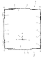
- the movable wing 3 can be relative to the fixed Frame 1 and the fixed wing or door panel 2 the closed position indicated in FIGS. 1 and 2 on the one hand be brought into the tilt opening position, as in the 3 and 4 can be seen. He can be compared to that fixed frame 1 and the fixed wing or fixed door panel 2 but also in parallel bring parked position and then out of the area of Through opening 4 of the fixed frame 1 in Horizontal direction in front of the fixed wing or that move the fixed door panel 2 as shown in FIGS. 5 and 6 can be seen.
- the upper display device 6 and the lower Display device 7 can be kinematically similar to one another be interpreted. But you can also fundamentally received different configurations.
- the lower opening device 7 is in any case to be interpreted as the weight of the movable wing 3 carries safely while running with a track 8a at the bottom Crossbar of the fixed frame 1 cooperates.
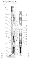
- the actuator 5 drives this - not visible here Locking rod on, which in the locking position A 1 and 2 with fixed in the frame fold 9 Locking elements 10 - as can be seen in Fig. 5 - interacts. Should the wing 3 in the open position 3 and 4 are transferred, that will Actuator 5 in the corresponding switch position B 3 and 4 brought. About the locking linkage the upper opening devices 6 are actuated and cause the wing 3 to be set down from the frame 1. The lower one horizontal end of wing 3 is through - not here visible - devices in this switch position on the frame 1 held.
- a corner drive 16, 16 ' is installed. I.e. it are two upper corner deflections 16 'and two lower ones Corner drives 16 are present, which over each other Intermediate pieces 17 are in a geared actuating connection.
- the actuation of the drive rod fitting 15 takes place via the Control 5 and a movable with its help Transmission 18. This is designed so that it is the Rotary movement of the operating element 5 in a pushing movement of the connecting rod fitting 15 converts.
- the transmission 18 moving connecting rod engages one at the top and one at the bottom Corner deflection 16 or 16 '.
- Each of these corner drives 16 or 16 ' stands by a horizontal intermediate piece 17 with a further corner deflection 16 or 16 ', in Connection. There are two corner drives 16 and 16 ' again by a vertical intermediate piece 17 and that Gearbox 18 coupled with each other.
- the two upper corner drives 16 'of Espagnolette fitting 15 is an upper one Display device 6 assigned to the wing 3 over Fasteners, such as screws, are mounted can and overlaps to frame 1.
- the motion control of the upper display devices 6 is used as the Espagnolette fitting 15 trained locking fitting causes, with the intermediary of coupling pieces 19, on the upper horizontal leg of each corner drive 16 provided and in the longitudinal direction of the upper wing spar are slidably arranged.
- the intermediate pieces 17 and the gear 18 are arranged to be longitudinally displaceable Bolt pin 20 arranged by the drive rod fitting 15 can be moved and with the frame fixed Interlocking elements 10 cooperate.
- Corner drives 16 On the lower horizontal legs of the two lower ones Corner drives 16 are devices 21 for fixing the lower horizontal wing section in the tilt-open position attached to the lower cross member of the fixed frame 1 fastened elements 22, 23 cooperate.
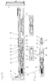
- the device 21 is, as shown in FIGS. 8 and 9, on the Fixed corner deflection 16 and acts via a first link 25 together with the element 22 designed as a blocking element.
- the locking link - of the device 21 On the first link 25 - the locking link - of the device 21 is a spring tab 29 fixed, on the Cover bracket or face plate 28 facing the top of the first link 25.
- On the cover bracket or the faceplate 28 is also a locking guide forming a fixing element 31 provided. It is with legs 32 on the cover bracket or the faceplate 28 attached and as a U-shaped part educated.
- This locking guide 31 is in that of the U-legs 32 and a U-web 33 connecting them limited free space in the longitudinal direction of the cover angle or the faceplate 28 penetrated by the spring tab 29.
- the Locking guide 31 is spaced from the first link 25 attached so that there is an exposed length of the Spring tab 29 results.
- the U-legs 32 form one Contact edge 32 'for angled on the spring tab 29 Lugs 34, and thus limit the end position of the first Link 25 or the spring tab 29.
- the first link 25 - the locking member - is namely by a Return spring 35, which in the exemplary embodiment as Helical compression spring is formed in a Locked position representing the end thrust position.
- the Return spring 35 is supported in a guide housing 36 from.
- the guide housing 36, the first link - that Locking element 25 -, the return spring 35 and the spring tab 29 form a structural unit on which the hardware groove or the cover rod covering the drive rod 26 or the Face plate 28 is releasably fixed.
- the first link 25 projects - The locking member - in the locking position from above and sideways into the element 22 and locks onto this Way, as well as the second link 27 in connection with the Element 23, the wing 3 on the frame 1.
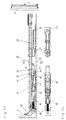
- results 12 - 13 show - that the second link 27 the first link 25 from the element 22 sideways - to left - displaced.
- the latching device can only be triggered if the wing 3 from the parallel storage position to the tilt position or the Closed position transferred and at the same time the Espagnolette fitting 15 at least in the rocker switch position brought.
- a second device 21 can also be used be provided on the lower cross member of the wing 3, for example to securely fix a very large one Ensure wing 3. In this case, too Attachment of the device 21 on the cover rail or Face plate 28. Due to the given switching direction or direction of movement 41 of the drive rod 26 must, however second device 21 in the direction of movement of the second Link 27 are attached. It follows from this that the second device 21 not as in FIGS. 8 to 15 shown - is near the wing corner, but in Switching direction or direction of movement 41 more to the center of the wing must be arranged.
- Wing 3 shown is for releasing the Through opening 4 shifted from left to right, whereby the gear 18 of the connecting rod fitting 15 in the left vertical spar of the wing 3 is attached.
- gear 18 of the connecting rod fitting 15 in the left vertical spar of the wing 3 is attached.
- For one of wing 3 opening right to left thus results in a mirrored arrangement of all functional parts.
- the Shift positions of the transmission 18 are retained, however whereby a wing 3 designed in this way opposite to the switching direction or direction of movement 41 directional drive rod movement results.
- the corner drives 16, 16 'and the devices 21 each longitudinally symmetrical.
- the first link 25 - locking member - the return spring 35 and the spring tab 29 form together with the Return spring 35 at least partially encompassing and that first link 25 - locking link - leading guide housing 36 a unit on which the drive rod 26 covering Cover angle or on the faceplate 28 of a corner drive 16 is releasably set.
- the element 22 has one approximately C-shaped cross section.
- the engaging first link 25 - the locking member - also has a complementary, the shape of an inverted T or a lying H having cross-section.
- the cross section of the first link 25 - the locking member - is with play on the cross section of the element 22 matched that the tilt position according to FIG. 3rd and 4 can be achieved without the relocation of the Wing 3 around a lower horizontal axis through the Intervention locking is prevented.
- That formed from the element 23 and the second link 27 Locking is in an analogous manner with engagement play built up. It is an advantage if the Elements 22, 23 are conventional locking elements, which in a variety of embodiments for different profiles of frame systems available are.
- the other fixing element Locking guide 31 formed from a U-shaped part, which with its connected by the U-web 33 U-legs 32 on the Cover bracket or the faceplate 28 is attached.
- the thereby delimited free space 42 is in the longitudinal direction of the Cover angle or the faceplate 28 of the spring tab 29th penetrated.
- the U-shaped part firmly with the cover bracket or the faceplate 28 connected.
- this connection can be taken for granted designed to be detachable and with suitable fasteners, for example screws, can be achieved by a universal Availability of the corner drive 16 to achieve.
- the devices 21 can of course also be used for fittings that allow two different opening positions, the second opening position being different Opening movement is as the parallel parking described of wing 3.
Landscapes
- Engineering & Computer Science (AREA)
- Mechanical Engineering (AREA)
- Window Of Vehicle (AREA)
- Wing Frames And Configurations (AREA)
- Specific Sealing Or Ventilating Devices For Doors And Windows (AREA)
- Power-Operated Mechanisms For Wings (AREA)
- Closing And Opening Devices For Wings, And Checks For Wings (AREA)
Description
- mit einem mittels eines Betätigungsorgans bedienbaren Verschlußgestänge des Flügels, das sich vom Betätigungsorgan aus wenigstens entlang des den Kipplagern benachbarten, unteren Flügelholmes erstreckt,
- wobei der Flügel an diesem Flügelholm über eine, zum Beschlag gehörende, durch das Verschlußgestänge lösbare, in ihrer Arbeitsstellung die Abstellbewegung sperrende Vorrichtung mit dem festen Rahmen gekuppelt und der untere Flügelholm in der gelösten Stellung der Vorrichtung in Abstellrichtung freigegeben ist,
- wobei außerdem die Vorrichtung ein am unteren Querholm des festen Rahmens od. dgl. befestigtes Element und ein am unteren Flügelholm gegenüber einem Deckwinkel bzw. einer Stulpschiene verschiebbares Glied aufweist und letzteres in seiner Arbeitsstellung eine Kante des Elementes hintergreift,
- wobei das Glied als gegen den Widerstand einer Rückstellfeder in die entsperrte Stellung verschiebbares, am Deckwinkel bzw. an der Stulpschiene geführtes Sperrglied ausgebildet ist,
- und wobei die Rückstellfeder, insbesondere eine Schraubendruckfeder zwischen das Sperrglied und eine flügelfeste Kante, Fläche od. dgl. eingesetzt ist und das Element als Sperrelement ausgebildet ist.
- daß die Sperr-Vorrichtung ein zweites gegenüber der Stulpschiene verschiebbares Glied aufweist, welches mit der von der Stulpschiene abgedeckten Treibstange über deren gesamten von einer Verschluß-Schaltstellung über eine Kippöffnungs-Schaltstellung bis in eine End-Schaltstellung reichenden Stellweg hinweg formschlüssig bewegbar gekuppelt ist,
- daß das erste gegenüber der Stulpschiene verschiebbare Glied - das Sperrglied - dieser Sperr-Vorrichtung relativ zum Deckwinkel bzw. zur Stulpschiene in seiner gegen den Widerstand der Rückstellfeder entsperrten Stellung mittels Fixierelemente selbsttätig fixierbar ist,
- daß die Fixierelemente für das erste Glied - das Sperrglied - der Sperr-Vorrichtung einerseits in einem der End-Schaltstellung unmittelbar benachbarten Bereich des Stellweges für das zweite Glied vorgesehen sind sowie sich andererseits im montierten Zustand in einem Abschnitt am unteren Flügelholm befinden, der dem am Querholm des festen Rahmens od. dgl. befestigten Element überlagert ist,
- und daß die Fixierelemente für das erste Glied - das Sperrglied - einerseits mittels des zweiten Gliedes ihrer Fixierposition zustellbar und andererseits durch das rahmenseitige Element aus ihrer Fixierstellung verdrängbar sind.
- Fig. 1 und 2
- in Stirnansicht und Seitenansicht eine parallelabstellbare Kippschiebetür bei Schließstellung des Flügels,
- Fig. 3 und 4
- in Stirnansicht und Seitenansicht, die parallelabstellbare Kippschiebetür bei in Kippstellung geöffnetem Flügel,
- Fig. 5 und 6
- in Stirnansicht und Seitenansicht die parallelabstellbare Kippschiebetür bei parallel abgestellten und horizontal in Öffnungsstellung abgeschobenem Flügel,
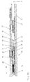
- Fig. 7
- eine Übersicht über den Verriegelungsbeschlag eines zumindest kippbaren und parallelabstellbaren Flügels eines Fensters, einer Tür od. dgl.,
- Fig. 8
- eine Sperr-Vorrichtung bei Verschlußstellung des Verriegelungsbeschlages in einer Seitenansicht
- Fig. 9
- die Sperr-Vorrichtung nach Fig. 8 in einer Draufsicht ohne Eckumlenkung
- Fig. 10
- die Sperr-Vorrichtung in der Kippstellung und in einer Seitenansicht,
- Fig. 11
- die Sperr-Vorrichtung nach Fig. 10 in einer Draufsicht ohne Eckumlenkung,
- Fig. 12
- die Sperr-Vorrichtung in der End-Schaltstelung in einer Seitenansicht,
- Fig. 13
- die Sperr-Vorrichtung nach Fig. 12 in einer Draufsicht ohne Eckumlenkung,
- Fig. 14
- die Sperr-Vorrichtung bei ausgestelltem und parallel abgestelltem Flügel, dessen Verriegelungsbeschlag in die Kipp-Stellung zurückgeführt ist,
- Fig. 15
- die Sperr-Vorrichtung nach Fig. 14 in einer Draufsicht ohne Eckumlenkung,
- Fig. 16
- die Sperr-Vorrichtung nach Fig. 8 an der dem Bedienorgan gegenüberliegenden unteren Ecke,
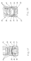
- Fig. 17
- einem Schnitt durch das Sperrglied und das Sperrelement der Sperr-Vorrichtung, und
- Fig. 18
- einen Schnitt durch das Fixierelement der Sperr-Vorrichtung.
- 1
- Rahmen
- 2
- festes Türfeld
- 3
- Flügel
- 4
- Durchgangsöffnung
- 5
- Betätigungsorgan
- 6
- obere Ausstellvorrichtung
- 7
- untere Ausstellvorrichtung
- 8
- horizontale Schiebeführung
- 9
- Rahmenfal
- 10
- Verriegelungselemente
- 15
- Treibstangenbeschlag
- 16
- Eckumlenkung
- 16
- obere Eckumlenkung
- 17
- Zwischenstücke
- 18
- Getriebe
- 19
- Kupplungsstück
- 20
- Riegelzapfen
- 21
- Vorrichtung
- 22
- Element
- 23
- Element
- 25
- erstes Glied - Sperrglied -
- 26
- Treibstange
- 27
- zweites Glied
- 28
- Deckwinkel bzw. Stulpschiene
- 29
- Federlasche
- 31
- Rastführung
- 32
- U-Schenkel
- 32 '
- Anschlagkante
- 33
- U-Steg
- 34
- Rastnase
- 35
- Rückstellfeder
- 36
- Führungsgehäuse
- 37
- freies Ende
- 38
- Anschlaglappen
- 39
- Rastkante
- 40
- Auflaufnocken
- 41
- Schaltrichtung bzw. Bewegungsrichtung
- 42
- Freiraum
- 43
- Längsränder
- 44
- Anlaufschrägen
- 45
- Längsränder
- 46
- Anlaufschrägen
Claims (10)
- Beschlag für einen zumindest kippbaren und parallel abstellbaren Flügel (3) eines einen festen Rahmen (1) aufweisenden Fensters, einer Tür od. dgl.,dadurch gekennzeichnet,mit einem mittels eines Betätigungsorgans (5) bedienbaren Verschlußgestänge des Flügels (3), das sich vom Betätigungsorgan (5) aus wenigstens entlang des den Kipplagern benachbarten, unteren Flügelholmes erstreckt,wobei der Flügel (3) an diesem Flügelholm über eine, zum Beschlag gehörende, durch das Verschlußgestänge lösbare, in ihrer Arbeitsstellung die Abstellbewegung sperrende Vorrichtung (21) mit dem festen Rahmen (1) gekuppelt und der untere Flügelholm in der gelösten Stellung der Vorrichtung (21) in Abstellrichtung freigegeben ist,wobei außerdem die Vorrichtung ein am unteren Querholm des festen Rahmens od. dgl. befestigtes Element (22) und ein am unteren Flügelholm gegenüber einem Deckwinkel bzw. einer Stulpschiene (28) verschiebbares Glied (25) aufweist und letzteres in seiner Arbeitsstellung eine Kante des Elementes (22) hintergreift,wobei das Glied (25) als gegen den Widerstand einer Rückstellfeder (35) in die entsperrte Stellung verschiebbares, am Deckwinkel bzw. an der Stulpschiene geführtes Sperrglied ausgebildet ist,und wobei die Rückstellfeder (35), insbesondere eine Schraubendruckfeder, zwischen das Sperrglied und eine flügelfeste Kante, Fläche od. dgl. eingesetzt ist und das Element (22) als Sperrelement ausgebildet ist,daß die Vorrichtung (21) ein zweites gegenüber dem Deckwinkel bzw. der Stulpschiene (28) verschiebbares Glied (27) aufweist, welches mit einer von dem Deckwinkel bzw. der Stulpschiene (28) abgedeckten Treibstange (26) des Verschlußgestänges über deren gesamten von einer Verschluß-Schaltstellung über eine Kippöffnungs-Schaltstellung bis in eine End-Schaltstellung reichenden Stellweg hinweg formschlüssig bewegbar gekuppelt ist,daß das erste gegenüber dem Deckwinkel bzw. der Stulpschiene (28) verschiebbare Glied - das Sperrglied - dieser Vorrichtung (21) relativ zum Deckwinkel bzw. zur Stulpschiene (28) in seiner gegen den Widerstand der Rückstellfeder (35) entsperrten Stellung mittels Fixierelemente selbsttätig fixierbar ist,daß die Fixierelemente für das erste Glied (25) - das Sperrglied - der Vorrichtung (21) einerseits in einem der End-Schaltstellung unmittelbar benachbarten Bereich des Stellweges für das zweite Glied (27) vorgesehen sind sowie sich andererseits im montierten Zustand in einem Abschnitt am unteren Flügelholm befinden, der dem am Querholm des festen Rahmens (1) od. dgl. befestigten Element (22) überlagert ist,und daß die Fixierelemente für das erste Glied 25 - das Sperrglied - einerseits mittels des zweiten Gliedes (27) ihrer Fixierposition zustellbar und andererseits durch das rahmenseitige Element (22) aus ihrer Fixierstellung verdrängbar sind.
- Beschlag nach Anspruch 1,
dadurch gekennzeichnet, daß das zweite verschiebbare Glied (27) ein Verschluß-Riegelglied bildet, dem am Querholm des festen Rahmens (1) od. dgl. in einer der Verschluß-Schaltstellung der Treibstange (26) entsprechenden Position bei in Schließstellung am festen Rahmen (1) od. dgl. anliegendem Flügel (3) ein zweites Element (23) als Verschluß-Riegelelement zugeordnet ist. - Beschlag nach einem der Ansprüche 1 und 2,
dadurch gekennzeichnet, daß eines der Fixierelemente aus einer am verschiebbaren ersten Glied 25 - dem Sperrglied - über ihr eines Ende befestigten Federlasche (29) besteht, die mit ihrem freien, anderem Ende dem ersten Glied (25) - Sperrglied - in Wirkrichtung der Rückstellfeder (35) voreilend angeordnet ist, während das andere Fixierelement von einer ortsfest an dem Deckwinkel bzw. der Stulpschiene (28) befestigten Rastführung (31) gebildet ist, und daß dabei in der Arbeitsstellung des ersten Gliedes (25) - des Sperrgliedes - das freie Ende der Federlasche (29) die Rastführung (31) in Richtung auf das zweite Glied (27) der Vorrichtung mindestens um den Entsperr-Stellweg des ersten Gliedes - des Sperrgliedes - überragt, während sich mit Abstand hinter dem freien Ende an der Federlasche (29) eine Rastnase (34) befindet, die in der EntsperrStellung des ersten Gliedes (25) - des Sperrgliedes - ein Widerlager der Rastführung (31) hinterfaßt. - Beschlag nach Anspruch 3,
dadurch gekennzeichnet, daß die als Fixierelement vorgesehen Rastführung (31) einen Abstand vom ersten Glied - dem Sperrglied - der Vorrichtung (21) hat und innerhalb dieses Abstandsbereichs ein Längenabschnitt der Federlasche (29) freiliegt, wobei von diesem Längenabschnitt der Federlasche (29) ein Auflaufnocken (40) als Auslöser für die Rastnase (34) in den Wirkbereich des am unteren Querholm des festen Rahmens (1) od. dgl. befestigten ersten Elementes (22) hineinragt. - Beschlag nach einem der Ansprüche 3 oder 4,
dadurch gekennzeichnet, daß die das andere Fixierelement bildende Rastführung (31) aus einem mit seinen Schenkeln an der Stulpschiene (28) befestigten U-Formteil besteht, dessen von den U-Schenkeln (32) und dem U-Steg (33) eingegrenzter Freiraum (42) in Längsrichtung des Deckwinkels bzw. der Stulpschiene (28) von der Federlasche durchgriffen ist. - Beschlag nach einem der Ansprüche 3 bis 5,
dadurch gekennzeichnet, daß das erste Glied (25), das Sperrglied mit der Rückstellfeder (35) und der das eine Fixierelement bildenden Federlasche (29) sowie einem Führungsgehäuse (36) eine Baueinheit bildet, die an der die Treibstange (26) abdeckenden Stulpschiene (28), insbesondere dem Deckwinkel (28) einer Eckumlenkung, lösbar festgelegt ist. - Beschlag nach einem der Ansprüche 1 bis 6,
dadurch gekennzeichnet, daß die im montierten Zustand am unteren Querholm des festen Rahmens (1) od. dgl. befestigten Elemente (22, 23) jeweils einen etwa C-förmigen Querschnitt als Riegeleingriff aufweisen, während das am unteren Flügelholm befindliche erste Glied (25) - das Sperrglied - und das zweite Glied (25) einen dazu komplementären Querschnitt, z.B. etwa umgekehrt T-förmigen oder aber liegend H-förmigen Querschnitt haben. - Beschlag nach einem der Ansprüche 3 bis 6,
dadurch gekennzeichnet, daß die Federlasche (29) an ihrem freien Ende (37) einen abgewinkelten Anschlaglappen (38) für das zweite Glied (27) der Vorrichtung (21) aufweist. - Beschlag nach Anspruch 4,
dadurch gekennzeichnet, daß die Federlasche (29) des ersten Gliedes (25) - des Sperrgliedes - zumindest seitlich neben dem Auflaufnocken (40) an ihren Längsrändern (43) Anlaufschrägen (44) hat und daß auch das ihm am unteren Querholm des festen Rahmens (1) od. dgl. zugeordnete Element (22) an seinen Längsrändern (46) mit Anlaufschrägen (45) versehen ist. - Beschlag nach einem der Ansprüche 1 bis 9,
dadurch gekennzeichnet, daß sämtliche Funktionsteile der Vorrichtung (21) eine zur Längsmittelebene des Deckwinkels bzw. der Stulpschiene (28) symmetrische Bauform aufweisen.
Applications Claiming Priority (2)
| Application Number | Priority Date | Filing Date | Title |
|---|---|---|---|
| DE29606168U DE29606168U1 (de) | 1996-04-03 | 1996-04-03 | Beschlag für einen zumindest kippbaren und parallel abstellbaren Flügel eines einen festen Rahmen aufweisenden Fensters, einer Tür o.dgl. |
| DE29606168U | 1996-04-03 |
Publications (3)
| Publication Number | Publication Date |
|---|---|
| EP0799960A2 EP0799960A2 (de) | 1997-10-08 |
| EP0799960A3 EP0799960A3 (de) | 2000-06-07 |
| EP0799960B1 true EP0799960B1 (de) | 2004-03-24 |
Family
ID=8022116
Family Applications (1)
| Application Number | Title | Priority Date | Filing Date |
|---|---|---|---|
| EP97102517A Expired - Lifetime EP0799960B1 (de) | 1996-04-03 | 1997-02-14 | Beschlag für einen zumindest kippbaren und parallel abstellbaren Flügel eines einen festen Rahmen aufweisenden Fensters, einer Tür od. dgl. |
Country Status (4)
| Country | Link |
|---|---|
| EP (1) | EP0799960B1 (de) |
| AT (1) | ATE262639T1 (de) |
| DE (2) | DE29606168U1 (de) |
| TR (1) | TR199700247A2 (de) |
Families Citing this family (4)
| Publication number | Priority date | Publication date | Assignee | Title |
|---|---|---|---|---|
| ES2255877B1 (es) * | 2005-08-01 | 2007-03-16 | Alma Expansion, S.L. | Dispositivo de bloqueo de reenvio para oscilo-batientes. |
| DE202005013427U1 (de) * | 2005-08-16 | 2005-11-10 | Gretsch-Unitas GmbH Baubeschläge | Beschlag |
| DE102007017441B3 (de) * | 2007-04-02 | 2008-10-16 | Roto Frank Ag | Treibstangenanordnung mit mindestens einer Treibstange und mindestens einem Treibstangenführungselement |
| CN110821349B (zh) * | 2018-08-11 | 2024-08-20 | 河北奥润顺达窗业有限公司 | 一种铝合金双扇门 |
Family Cites Families (3)
| Publication number | Priority date | Publication date | Assignee | Title |
|---|---|---|---|---|
| DE3033751C2 (de) * | 1980-09-08 | 1986-01-23 | Schaumburg-Lippische Baubeschlag-Fabrik W. Hautau GmbH, 3068 Helpsen | Beschlag für den Schiebeflügel von Fenstern, Türen oder dgl. aus Holz- oder Kunststoffprofilen |
| DE3310020C3 (de) * | 1983-03-19 | 1997-09-04 | Gretsch Unitas Gmbh | Beschlag für einen zumindest kippbaren und parallelabstellbaren Flügel eines Fensters, einer Tür od. dgl. |
| DE8805556U1 (de) * | 1988-04-27 | 1988-06-16 | Gretsch-Unitas GmbH Baubeschläge, 7257 Ditzingen | Beschlag für einen zumindest kippbaren und parallelabstellbaren Flügel eines Fensters, einer Tür od. dgl. |
-
1996
- 1996-04-03 DE DE29606168U patent/DE29606168U1/de not_active Expired - Lifetime
-
1997
- 1997-02-14 EP EP97102517A patent/EP0799960B1/de not_active Expired - Lifetime
- 1997-02-14 DE DE59711436T patent/DE59711436D1/de not_active Expired - Fee Related
- 1997-02-14 AT AT97102517T patent/ATE262639T1/de not_active IP Right Cessation
- 1997-04-03 TR TR97/00247A patent/TR199700247A2/xx unknown
Also Published As
| Publication number | Publication date |
|---|---|
| TR199700247A3 (tr) | 1997-10-21 |
| DE59711436D1 (de) | 2004-04-29 |
| TR199700247A2 (xx) | 1997-10-21 |
| EP0799960A2 (de) | 1997-10-08 |
| DE29606168U1 (de) | 1996-06-20 |
| ATE262639T1 (de) | 2004-04-15 |
| EP0799960A3 (de) | 2000-06-07 |
Similar Documents
| Publication | Publication Date | Title |
|---|---|---|
| DE2603240C2 (de) | Beschlag für einen kipp- und schiebbaren Flügel von Fenstern, Türen o.dgl. | |
| DE2920581A1 (de) | Stellvorrichtung zum ein- und ausruecken der riegelglieder an verschluessen, insbesondere mittelverschluessen, von fenstern, tueren o.dgl. | |
| EP0119433B2 (de) | Beschlag für einen zumindest kippbaren und parallelabstellbaren Flügel eines Fensters, einer Tür od. dgl. | |
| DE29811395U1 (de) | Treibstangenverschluß | |
| EP0249683B2 (de) | Verschlussvorrichtung für die Flügel von Fenstern, Türen od.dgl. | |
| EP0152791B1 (de) | Stellvorrichtung für Schiebeflügel von Fenstern, Türen od. dgl. | |
| EP4473180A1 (de) | Verlagerungsvorrichtung zur zwangsweisen verlagerung eines flügels, insbesondere eines schiebeflügels, eines fensters oder einer tür | |
| EP0799960B1 (de) | Beschlag für einen zumindest kippbaren und parallel abstellbaren Flügel eines einen festen Rahmen aufweisenden Fensters, einer Tür od. dgl. | |
| EP3109385B1 (de) | Verschlussvorrichtung für ein tor mit einem ein- oder mehrteiligen torblatt | |
| EP2140087B1 (de) | Beschlag | |
| DE7816563U1 (de) | Schiebe-kipp-tuer oder -fenster | |
| EP1264954B1 (de) | Verriegelungsvorrichtung | |
| DE4202085C2 (de) | Verschluss fuer rolladenschraenke | |
| WO2024037763A1 (de) | Verlagerungsvorrichtung zur zwangsweisen verlagerung eines flügels, insbesondere eines schiebeflügels, eines fensters oder einer tür | |
| WO2023143823A1 (de) | Verlagerungsvorrichtung zur zwangsweisen verlagerung eines flügels, insbesondere eines schiebeflügels, eines fensters oder einer tür | |
| DE2646905C2 (de) | Beschlag für einen kipp- und schiebbaren Flügel von Fenstern, Türen od. dgl. | |
| DE3221110A1 (de) | Beschlag fuer einen kipp- und nachfolgend mindestens parallelabstellbaren fluegel eines fensters, einer tuer od. dgl. | |
| EP0262347B1 (de) | Ausstellvorrichtung für den wenigstens drehbaren Flügel eines Fensters, einer Tür od. dgl. | |
| DE3041221C2 (de) | Verriegelungsbeschlag an einem Kipp-Schiebeflügel, vorzugsweise Hebe-Kipp-Schiebeflügel, von Fenstern, Türen od.dgl. | |
| DE2243916A1 (de) | Kippriegel-verschlussbeschlag fuer kipp-schwenkfluegel-fenster und -tueren od. dgl | |
| DE6935673U (de) | Bedienungssperre fuer treibstangenbeschlaege, insbesondere kipp-schwenkfluegel-beschlaege | |
| DE9114374U1 (de) | Treibstangenbeschlag für Fenster, Türen o.dgl. | |
| EP1231345B1 (de) | Gesteuerte Verriegelungsvorrichtung und Eckumlenkung | |
| EP3350394B1 (de) | Treibstangenbeschlag | |
| EP0811741A2 (de) | Schiebetür, Schiebefenster od.dgl. |
Legal Events
| Date | Code | Title | Description |
|---|---|---|---|
| PUAI | Public reference made under article 153(3) epc to a published international application that has entered the european phase |
Free format text: ORIGINAL CODE: 0009012 |
|
| AK | Designated contracting states |
Kind code of ref document: A2 Designated state(s): AT BE CH DE ES FR GB IT LI NL |
|
| PUAL | Search report despatched |
Free format text: ORIGINAL CODE: 0009013 |
|
| AK | Designated contracting states |
Kind code of ref document: A3 Designated state(s): AT BE CH DE ES FR GB IT LI NL |
|
| 17P | Request for examination filed |
Effective date: 20000620 |
|
| RAP1 | Party data changed (applicant data changed or rights of an application transferred) |
Owner name: SIEGENIA-AUBI KG |
|
| RAP1 | Party data changed (applicant data changed or rights of an application transferred) |
Owner name: SIEGENIA-AUBI KG |
|
| GRAP | Despatch of communication of intention to grant a patent |
Free format text: ORIGINAL CODE: EPIDOSNIGR1 |
|
| GRAS | Grant fee paid |
Free format text: ORIGINAL CODE: EPIDOSNIGR3 |
|
| GRAA | (expected) grant |
Free format text: ORIGINAL CODE: 0009210 |
|
| AK | Designated contracting states |
Kind code of ref document: B1 Designated state(s): AT BE CH DE ES FR GB IT LI NL |
|
| PG25 | Lapsed in a contracting state [announced via postgrant information from national office to epo] |
Ref country code: NL Free format text: LAPSE BECAUSE OF FAILURE TO SUBMIT A TRANSLATION OF THE DESCRIPTION OR TO PAY THE FEE WITHIN THE PRESCRIBED TIME-LIMIT Effective date: 20040324 Ref country code: IT Free format text: LAPSE BECAUSE OF FAILURE TO SUBMIT A TRANSLATION OF THE DESCRIPTION OR TO PAY THE FEE WITHIN THE PRESCRIBED TIME-LIMIT;WARNING: LAPSES OF ITALIAN PATENTS WITH EFFECTIVE DATE BEFORE 2007 MAY HAVE OCCURRED AT ANY TIME BEFORE 2007. THE CORRECT EFFECTIVE DATE MAY BE DIFFERENT FROM THE ONE RECORDED. Effective date: 20040324 |
|
| REG | Reference to a national code |
Ref country code: GB Ref legal event code: FG4D Free format text: NOT ENGLISH |
|
| REG | Reference to a national code |
Ref country code: CH Ref legal event code: NV Representative=s name: PA ALDO ROEMPLER Ref country code: CH Ref legal event code: EP |
|
| GBT | Gb: translation of ep patent filed (gb section 77(6)(a)/1977) |
Effective date: 20040324 |
|
| REF | Corresponds to: |
Ref document number: 59711436 Country of ref document: DE Date of ref document: 20040429 Kind code of ref document: P |
|
| RAP2 | Party data changed (patent owner data changed or rights of a patent transferred) |
Owner name: SIEGENIA-AUBI KG |
|
| PG25 | Lapsed in a contracting state [announced via postgrant information from national office to epo] |
Ref country code: ES Free format text: LAPSE BECAUSE OF FAILURE TO SUBMIT A TRANSLATION OF THE DESCRIPTION OR TO PAY THE FEE WITHIN THE PRESCRIBED TIME-LIMIT Effective date: 20040705 |
|
| REG | Reference to a national code |
Ref country code: CH Ref legal event code: PFA Owner name: SIEGENIA-AUBI KG Free format text: SIEGENIA-AUBI KG#EISENHUETTENSTRASSE 22#57074 SIEGEN (DE) -TRANSFER TO- SIEGENIA-AUBI KG#INDUSTRIESTRASSE 1-3#57234 WILNSDORF (DE) |
|
| NLT2 | Nl: modifications (of names), taken from the european patent patent bulletin |
Owner name: SIEGENIA-AUBI KG |
|
| NLV1 | Nl: lapsed or annulled due to failure to fulfill the requirements of art. 29p and 29m of the patents act | ||
| ET | Fr: translation filed | ||
| PGFP | Annual fee paid to national office [announced via postgrant information from national office to epo] |
Ref country code: GB Payment date: 20050124 Year of fee payment: 9 |
|
| PLBE | No opposition filed within time limit |
Free format text: ORIGINAL CODE: 0009261 |
|
| STAA | Information on the status of an ep patent application or granted ep patent |
Free format text: STATUS: NO OPPOSITION FILED WITHIN TIME LIMIT |
|
| PGFP | Annual fee paid to national office [announced via postgrant information from national office to epo] |
Ref country code: FR Payment date: 20050217 Year of fee payment: 9 |
|
| PGFP | Annual fee paid to national office [announced via postgrant information from national office to epo] |
Ref country code: AT Payment date: 20050218 Year of fee payment: 9 |
|
| PGFP | Annual fee paid to national office [announced via postgrant information from national office to epo] |
Ref country code: CH Payment date: 20050221 Year of fee payment: 9 |
|
| PG25 | Lapsed in a contracting state [announced via postgrant information from national office to epo] |
Ref country code: BE Free format text: LAPSE BECAUSE OF NON-PAYMENT OF DUE FEES Effective date: 20050228 |
|
| PGFP | Annual fee paid to national office [announced via postgrant information from national office to epo] |
Ref country code: DE Payment date: 20050228 Year of fee payment: 9 |
|
| 26N | No opposition filed |
Effective date: 20041228 |
|
| BERE | Be: lapsed |
Owner name: *SIEGENIA-AUBI K.G. Effective date: 20050228 |
|
| PG25 | Lapsed in a contracting state [announced via postgrant information from national office to epo] |
Ref country code: GB Free format text: LAPSE BECAUSE OF NON-PAYMENT OF DUE FEES Effective date: 20060214 Ref country code: AT Free format text: LAPSE BECAUSE OF NON-PAYMENT OF DUE FEES Effective date: 20060214 |
|
| PG25 | Lapsed in a contracting state [announced via postgrant information from national office to epo] |
Ref country code: LI Free format text: LAPSE BECAUSE OF NON-PAYMENT OF DUE FEES Effective date: 20060228 Ref country code: CH Free format text: LAPSE BECAUSE OF NON-PAYMENT OF DUE FEES Effective date: 20060228 |
|
| PG25 | Lapsed in a contracting state [announced via postgrant information from national office to epo] |
Ref country code: DE Free format text: LAPSE BECAUSE OF NON-PAYMENT OF DUE FEES Effective date: 20060901 |
|
| REG | Reference to a national code |
Ref country code: CH Ref legal event code: PL |
|
| GBPC | Gb: european patent ceased through non-payment of renewal fee |
Effective date: 20060214 |
|
| REG | Reference to a national code |
Ref country code: FR Ref legal event code: ST Effective date: 20061031 |
|
| BERE | Be: lapsed |
Owner name: *SIEGENIA-AUBI K.G. Effective date: 20050228 |
|
| PG25 | Lapsed in a contracting state [announced via postgrant information from national office to epo] |
Ref country code: FR Free format text: LAPSE BECAUSE OF NON-PAYMENT OF DUE FEES Effective date: 20060228 |