EP1727719B1 - Magnetschwebebahn mit einer druckluft-versorgungsanlage - Google Patents
Magnetschwebebahn mit einer druckluft-versorgungsanlage Download PDFInfo
- Publication number
- EP1727719B1 EP1727719B1 EP05715084.9A EP05715084A EP1727719B1 EP 1727719 B1 EP1727719 B1 EP 1727719B1 EP 05715084 A EP05715084 A EP 05715084A EP 1727719 B1 EP1727719 B1 EP 1727719B1
- Authority
- EP
- European Patent Office
- Prior art keywords
- compressed air
- magnetic levitation
- vehicle
- vehicles
- levitation railway
- Prior art date
- Legal status (The legal status is an assumption and is not a legal conclusion. Google has not performed a legal analysis and makes no representation as to the accuracy of the status listed.)
- Expired - Lifetime
Links
Images

Classifications
-
- B—PERFORMING OPERATIONS; TRANSPORTING
- B60—VEHICLES IN GENERAL
- B60T—VEHICLE BRAKE CONTROL SYSTEMS OR PARTS THEREOF; BRAKE CONTROL SYSTEMS OR PARTS THEREOF, IN GENERAL; ARRANGEMENT OF BRAKING ELEMENTS ON VEHICLES IN GENERAL; PORTABLE DEVICES FOR PREVENTING UNWANTED MOVEMENT OF VEHICLES; VEHICLE MODIFICATIONS TO FACILITATE COOLING OF BRAKES
- B60T17/00—Component parts, details, or accessories of power brake systems not covered by groups B60T8/00, B60T13/00 or B60T15/00, or presenting other characteristic features
- B60T17/04—Arrangements of piping, valves in the piping, e.g. cut-off valves, couplings or air hoses
-
- B—PERFORMING OPERATIONS; TRANSPORTING
- B60—VEHICLES IN GENERAL
- B60T—VEHICLE BRAKE CONTROL SYSTEMS OR PARTS THEREOF; BRAKE CONTROL SYSTEMS OR PARTS THEREOF, IN GENERAL; ARRANGEMENT OF BRAKING ELEMENTS ON VEHICLES IN GENERAL; PORTABLE DEVICES FOR PREVENTING UNWANTED MOVEMENT OF VEHICLES; VEHICLE MODIFICATIONS TO FACILITATE COOLING OF BRAKES
- B60T11/00—Transmitting braking action from initiating means to ultimate brake actuator without power assistance or drive or where such assistance or drive is irrelevant
- B60T11/10—Transmitting braking action from initiating means to ultimate brake actuator without power assistance or drive or where such assistance or drive is irrelevant transmitting by fluid means, e.g. hydraulic
- B60T11/28—Valves specially adapted therefor
- B60T11/32—Automatic cut-off valves for defective pipes
-
- B—PERFORMING OPERATIONS; TRANSPORTING
- B60—VEHICLES IN GENERAL
- B60T—VEHICLE BRAKE CONTROL SYSTEMS OR PARTS THEREOF; BRAKE CONTROL SYSTEMS OR PARTS THEREOF, IN GENERAL; ARRANGEMENT OF BRAKING ELEMENTS ON VEHICLES IN GENERAL; PORTABLE DEVICES FOR PREVENTING UNWANTED MOVEMENT OF VEHICLES; VEHICLE MODIFICATIONS TO FACILITATE COOLING OF BRAKES
- B60T17/00—Component parts, details, or accessories of power brake systems not covered by groups B60T8/00, B60T13/00 or B60T15/00, or presenting other characteristic features
- B60T17/02—Arrangements of pumps or compressors, or control devices therefor
Definitions
- the invention relates to a magnetic levitation of the type specified in the preamble of claim 1.
- the technical problem to be solved by the invention is to provide in magnetic levitation trains of the type described in the introduction an air pressure supply system which, with relatively little construction and assembly costs ensures high redundancy.
- the invention has the advantage that each vehicle is provided with two continuous compressed air lines to which the consumers can be selectively connected. This makes it possible to connect the consumer in the event of failure of a compressed air line to the other, not defective compressed air line.
- Fig. 1 shows in cross-section a magnetic levitation vehicle 31, which is mounted in a conventional manner on a running in the longitudinal direction of a route track, which contains made of steel and / or concrete support 32 and mounted on these Fahrwegplatten 33.
- the drive of the magnetic levitation vehicle 31 is z. B. by means of a long stator motor, which is fastened below the track plate 33, in the longitudinal direction of successive, not shown, teeth and grooves, are inserted in the windings, which are fed with three-phase variable amplitude and frequency.
- the actual exciter field of the long stator motor is generated by at least one first, acting as a support magnet 35 magnet assembly which is attached to at least one side frame bracket 36 on the magnetic levitation vehicle 31 and the in Fig.
- the support magnet 35 not only provides the field of excitation, but also fulfills the function of carrying and levitating, by the operation of the magnetic levitation vehicle 31 a predetermined gap 37 of z. B. 10 mm between the support magnet 35 and the track or its Statorvolen 4 maintains.
- the track plate 33 laterally mounted guide rails 38, which are also mounted on the frame brackets 36 guide magnets 39 facing each other, which serve in operation to maintain a gap 37 corresponding gap 40 between itself and the guide rail 38.
- Magnetic levitation vehicles 31 and their magnet arrangements are the expert z. B. from the publications U.S. Patent 4,698,895 . DE 39 28 277 A1 and PCT WO 97/30504 A1 well known.
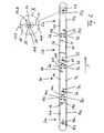
- Fig. 2 shows a presently considered best embodiment of the invention. Thereafter, a magnetic levitation is shown with two middle vehicles 1a and 1b and two end-side vehicles 2a and 2b, wherein all four vehicles 1, 2 are connected to a train with each other.
- the vehicle 1a includes a compressed air supply system having two compressed air lines 3a and 4a which extend in the longitudinal direction of the magnetic levitation through the vehicle 1a. Furthermore, the vehicle 1 a contains a consumer connection line 5 a, to which at least one not individually illustrated consumer such as an air conditioning system can be connected.
- the arrangement according to the invention is such that the connection line 5a can be selectively connected to the compressed air line 3a or the compressed air line 4a.
- the selection of the respective compressed air line 3a, 4a is preferably carried out by using a selector valve 6a connected between the connecting line 5a and the two compressed air lines 3a, 4a. With particular advantage this is an automatic working Selection valve 6a, for example, always connects the connection line 5a with that of the two compressed air lines 3a, 4a, which currently has the higher air pressure.
- the compressed air line 3a leads at one end of the vehicle to a compressed air connection 7a and at the other end of the vehicle to a compressed air connection 8a.
- the compressed air line 4a at one end of the vehicle leads to a compressed air connection 9a and at the other end of the vehicle to a compressed air connection 10a.
- the terminal 7a is located, for example, on the left and the terminal 9a on the right side of the vehicle when viewed in a direction indicated by an arrow v direction.
- the 8a belonging to the compressed air line 3a lies on the right side and the connection 10a belonging to the compressed air line 4a is on the left side of the vehicle.
- the end-side vehicle 2a has, analogously to the vehicle 1a, two compressed-air lines 12a and 14a, a consumer connection line 15a and a selection valve 16a connecting the intake line 15a to the two compressed-air lines 12a, 14a.
- the selector valve 16a corresponds in function to the selector valves 6a and 6b, respectively.
- a compressed air connection 17a for the compressed air line 12a is located on the vehicle end facing the vehicle 1a on the left side, while a compressed air connection 18a for the compressed air line 14a is located on the right side. How from there the compressed air lines 12a, 14a laid in the direction of the other end in the vehicle 2a, is insignificant for the invention. It is only important that both compressed air lines 12a, 14a are shut off at their ends remote from the terminals 17a, 18a.
- the vehicle 2b is finally formed like the vehicle 2a.
- the corresponding parts are therefore provided with the same reference numerals but in addition to the letter b instead of the letter a.
- the two vehicles 2a, 2b in the train are mirror images, i. arranged rotated by 180 ° to each other, so that the compressed-air connections 17b, 18b are arranged at the end of the vehicle 2b facing the vehicle 1b.
- each vehicle has its own, arranged in it itself and working eg with an operating pressure of 10 bar compressed air source 19 to 22 in the form of an active compressed air generator such as a compressor.
- the compressed air generator 19 is connected to the line 12a, the compressed air generator 20 to the line 3a, the compressed air generator 21 to the line 3b and finally the compressed air generator 22 to the compressed air line 14b. It follows that each train of compressed air of the train while in each vehicle 1a to 2b each one of these compressed air generator 19 to 22, but these, for example, viewed from left to right in the accompanying drawing, are alternately connected to the one or other continuous compressed air line.
- the one compressed air lines 3a, 3b of the middle vehicles 1a, 1b are therefore fed, for example, by a compressed air source 20, 21 located in the respective vehicle itself, while the other compressed air lines 4a, 4b of the vehicles 1 are connected to a compressed air source which consists of one of the connections 17a , 8b and 7a, 18b, etc. of a neighboring vehicle 2a, 1b and 1a, 2b, respectively.
- the described compressed air supply system offers numerous advantages.
- a compressed air line 12a, 4a, 3b, 12b or 14a, 3a, 4b, 14b completely fail without any of the vehicles involved 1, 2 without compressed air, since the consumers are then simply switched to the still intact compressed air line. In that regard, there is redundancy for all vehicles involved.
- middle and all end-side vehicles 1 and 2 can be formed exactly identical.
- the selector valves 6a, 6b provided in the rear and the compressed air generator 20, 21 in the front part of the vehicle. This results regardless of the order in which these vehicles 1 are connected to each other, no differences in terms of supply of compressed air.
- the end-side vehicles 2 which are used because of their coupling to the front and rear end of the train in each case rotated by 180 ° relative to each other positions.
- Another not inconsiderable advantage of the invention is the redundancy of the various compressed air generators. Even if a participating compressed air generator (e.g., 21) fails in a compressed air train (eg, 12a, 4a, 3b, 12b), that line is still supplied with compressed air by one of the other compressed air generators (e.g., 19).
- a participating compressed air generator e.g., 21
- a compressed air train e.g., 12a, 4a, 3b, 12b
- the selector valves 6a, 6b, 16a, 16b can in principle be operated manually, but are preferably designed and / or set up so that they automatically connect the consumer connection lines 5a, 5b, 15a and 15b to that compressed air line in which the higher one is currently Air pressure is present.
- selector valve 16b An embodiment of such a selector valve is in the enlargement of the X accompanying drawing illustrated by the selector valve 16b.
- This consists of a so-called shuttle valve having a compressed air passage 23 with two connected to the compressed air lines 12b 14b, formed in the manner of valve seats compressed air connections 24, 25, between which a ball 26 back and forth is slidably mounted.
- the consumer connection line 15b is connected to a central branch 27 of the passage 23, and the ball 26 can in each case one of the two terminals 24, 25 shut off.
- the selector valve 16b is designed in the manner of a double-acting check valve. Its mode of action is as follows:
- the ball 26 is automatically pressed against the terminal 25, so that it shuts off this, as the drawing shows.
- the consumer connection line 15b is then connected via the branch 27 to the compressed air line 14b. If, on the other hand, at any time the pressure in line 14b drops below the pressure in line 12b, then ball 26 is placed against port 24, thereby automatically disconnecting consumer line 15b via branch 27 to higher pressure line 12b connected. As a result, the consumer is always supplied with the currently highest air pressure, which is irrelevant whether this still the operating pressure of z. B. 10 bar or a lower pressure corresponds.
- the other selector valves 6a, 6b and 16a are the same as the selector valve 16b.
- the invention is not limited to the described embodiment, which could be modified in many ways.
- the compressed air lines 3a, 4a, etc. do not have to run on the sides of the vehicles 1a, etc., but may, in principle, be laid one on top of another at arbitrary locations and like the terminals 7a to 10a.
- the intersections 11a, 11b are shown only systematically.
- the associated compressed air ducts 3a, 4a, etc. could be crossed several times, in the case of the odd-numbered vehicles 1 and in the case of the vehicles 2 having an even number of crossing points.
- crossing is therefore to be understood in the context of the present invention, that the lines 3, 4 are arranged opposite to the respective other vehicle ends at the respective vehicle ends, thereby automatically achieve the described effect.
- additional compressed air lines and associated components may be provided to increase redundancy. It is also clear that in the event that the maglev is operated only with one of the vehicles 1 and 2, respectively to that compressed air line, which is not connected in the accompanying drawing with a self-arranged in the vehicle compressed air generator 19 to 22, an additional Compressed air source would have to be connected to ensure the desired redundancy.
Landscapes
- Engineering & Computer Science (AREA)
- Transportation (AREA)
- Mechanical Engineering (AREA)
- Electric Propulsion And Braking For Vehicles (AREA)
- Fluid-Pressure Circuits (AREA)
- Vehicle Body Suspensions (AREA)
Description
- Die Erfindung betrifft eine Magnetschwebebahn der im Oberbegriff des Anspruchs 1 angegebenen Gattung.
- Bei Magnetschwebebahnen dieser Art ist in der Regel jedes einzelne Fahrzeug, auch als Fahrzeugsektion bezeichnet, mit einer Druckluft-Versorgungsanlage versehen, die zur Versorgung verschiedener Verbraucher wie z. B. Luftfedern, Türantrieben, Klimaanlagen od. dgl. dienen. Fällt eine der Druckluft-Versorgungsanlagen aus, ist das betreffende Fahrzeug ohne Druckluft. Werden zur Vermeidung dieses Nachteils und aus Redundanzgründen zwei Druckluft-Versorgungsanlagen pro Fahrzeug vorgesehen, ergibt sich ein hoher Kosten- und Montageaufwand. Ähnliche Einrichtungen sind bei Schienenfahrzeugen bekannt (
DE 10 96 949 B ), wobei sie allerdings nicht zum direkten Anschluß am Verbraucher, sondern zur Füllung eines die Verbraucher speisenden Druckmittelbehälters dienen. - Entsprechende Probleme ergeben sich, wenn in jedem Fahrzeug eine durchgehende, an eine Druckluft-Versorgungsanlage angeschlossene Druckluftleitung vorhanden ist, die beim Ankoppeln zweier Fahrzeuge ebenfalls miteinander verbunden werden. Wird diese Druckluftleitung defekt, ist der ganze Zug ohne Druckluft.
- Das von der Erfindung zu lösende technische Problem besteht darin, bei Magnetschwebebahnen der eingangs bezeichneten Gattung eine Luftdruck-Versorgungsanlage vorzusehen, die bei verhältnismäßig geringem Konstruktions- und Montageaufwand eine hohe Redundanz gewährleistet.
- Zur Lösung dieser Aufgabe dienen die kennzeichnenden Merkmale des Anspruchs 1.
- Die Erfindung bringt den Vorteil mit sich, daß jedes Fahrzeug mit zwei durchgehenden Druckluftleitungen versehen ist, an die die Verbraucher wahlweise angeschlossen werden können. Dadurch ist es möglich, die Verbraucher beim Ausfall einer Druckluftleitung an die jeweils andere, nicht defekte Druckluftleitung anzuschließen.
- Weitere vorteilhafte Merkmale der Erfindung ergeben sich aus den Unteransprüchen.
- Die Erfindung wird nachfolgend an einem in den beiliegenden Zeichnungen dargestellten Ausführungsbeispiel näher erläutert. Es zeigen:
-
Fig. 1 einen schematischen Teilschnitt durch ein übliches Magnetschwebefahrzeug und einen zugehörigen Fahrweg, und -
Fig. 2 eine aus vier Fahrzeugen bzw. Sektionen zusammengesetzte Magnetschwebebahn in einer schematischen Draufsicht. -
Fig. 1 zeigt im Querschnitt ein Magnetschwebefahrzeug 31, das in üblicher Weise auf einem in Längsrichtung einer Trasse verlaufenden Fahrweg fahrbar montiert ist, der aus Stahl und/oder Beton hergestellte Träger 32 und auf diesen montierte Fahrwegplatten 33 enthält. Der Antrieb des Magnetschwebefahrzeugs 31 erfolgt z. B. mittels eines Langstatormotors, der unterhalb der Fahrwegplatte 33 befestigte, in deren Längsrichtung aufeinander folgende, nicht dargestellte Zähne und Nuten aufweist, in die Wicklungen eingelegt sind, die mit Drehstrom variabler Amplitude und Frequenz gespeist werden. Das eigentliche Erregerfeld des Langstatormotors wird durch wenigstens eine erste, als Tragmagnet 35 wirkende Magnetanordnung erzeugt, die mit wenigstens einem seitlichen Gestellbügel 36 am Magnetschwebefahrzeug 31 befestigt ist und den inFig. 1 nach unten offenen Nuten der Statorpakete 34 zugewandte Magnetpole aufweist. Der Tragmagnet 35 stellt nicht nur das Erregerfeld bereit, sondern erfüllt auch die Funktion des Tragens und Schwebens, indem er beim Betrieb des Magnetschwebefahrzeugs 31 einen vorgegebenen Spalt 37 von z. B. 10 mm zwischen dem Tragmagneten 35 und dem Fahrweg bzw. dessen Statorpaketen 4 aufrecht erhält. - Zur Spurführung des Magnetschwebefahrzeugs 31 weist die Fahrwegplatte 33 seitlich angebrachte Führschienen 38 auf, denen ebenfalls an den Gestellbügeln 36 montierte Führmagnete 39 gegenüberstehen, die beim Betrieb dazu dienen, zwischen sich und der Führschiene 38 einen dem Spalt 37 entsprechenden Spalt 40 aufrechtzuerhalten.
- Magnetschwebefahrzeuge 31 und deren Magnetanordnungen sind dem Fachmann z. B. aus den Druckschriften
US-PS 4,698,895 ,DE 39 28 277 A1 undPCT WO 97/30504 A1 -
Fig. 2 zeigt ein derzeit für am besten gehaltenes Ausführungsbeispiel der Erfindung. Danach ist eine Magnetschwebebahn mit zwei mittleren Fahrzeugen 1a und 1b und zwei endseitigen Fahrzeugen 2a und 2b dargestellt, wobei alle vier Fahrzeuge 1, 2 zu einem Zug miteinander verbunden sind. - Das Fahrzeug 1a enthält eine Druckluft-Versorgungsanlage, die zwei Druckluftleitungen 3a und 4a aufweist, die sich in Längsrichtung der Magnetschwebebahn durch das Fahrzeug 1a erstrecken. Ferner enthält das Fahrzeug 1a eine Verbraucher-Anschlußleitung 5a, an die wenigstens ein nicht einzeln dargestellter Verbraucher wie z.B. eine Klimaanlage angeschlossen sein kann. Dabei ist die Anordnung erfindungsgemäß so getroffen, daß die Anschlußleitung 5a wahlweise mit der Druckluftleitung 3a oder der Druckluftleitung 4a verbunden werden kann. Die Auswahl der jeweiligen Druckluftleitung 3a, 4a erfolgt vorzugsweise durch Anwendung eines zwischen die Anschlußleitung 5a und die beiden Druckluftleitungen 3a, 4a geschalteten Auswahlventils 6a. Mit besonderen Vorteil handelt es sich hierbei um ein automatisch arbeitendes Auswahlventil 6a, das die Anschlußleitung 5a z.B. stets mit derjenigen der beiden Druckluftleitungen 3a, 4a verbindet, die momentan den höheren Luftdruck hat.
- Die Druckluftleitung 3a führt an einem Fahrzeugende zu einem Druckluftanschluß 7a und am anderen Fahrzeugende zu einem Druckluftanschluß 8a. Entsprechend führt die Druckluftleitung 4a an einem Fahrzeugende zu einem Druckluftanschluß 9a und am anderen Fahrzeugende zu einem Druckluftanschluß 10a. Dabei liegt der Anschluß 7a z.B. auf der linken und der Anschluß 9a auf der rechten Fahrzeugseite bei Betrachtung in einer durch einen Pfeil v angegebenen Fahrtrichtung. Dagegen ist es am anderen Fahrzeugende umgekehrt, d.h. hier liegt der zur Druckluftleitung 3a gehörende 8a auf der rechten und der zur Druckluftleitung 4a gehörende Anschluß 10a auf der linken Fahrzeugseite. Das bedeutet, daß sich die beiden Druckluftleitungen 3a und 4a, wie durch eine mit 11 bezeichnete Kreuzungsstelle angedeutet ist, im Fahrzeug 1a irgendwo kreuzen.
- Beim Fahrzeug 1b ist die Anordnung zweckmäßig genauso wie beim Fahrzeug 1a. Die entsprechenden Teile sind daher mit denselben Bezugsziffern, jedoch zusätzlich mit den Buchstaben b statt mit den Buchstaben a versehen.
- Das endseitige Fahrzeug 2a weist analog zum Fahrzeug 1a zwei Druckluftleitungen 12a und 14a, eine Verbraucher-Anschlußleitung 15a und ein die Ansclußleitung 15a mit den beiden Druckluftleitungen 12a, 14a verbindendes Auswahlventil 16a auf. Das Auswahlventil 16a entspricht in seiner Funktion den Auswahlventilen 6a bzw. 6b.
- Ein Druckluftanschluß 17a für die Druckluftleitung 12a liegt an dem dem Fahrzeug 1a zugewandten Fahrzeugende auf der linken Seite, während ein Druckluftanschluß 18a für die Druckluftleitung 14a auf der rechten Seite liegt. Wie von dort die Druckluftleitungen 12a, 14a in Richtung des anderen Endes im Fahrzeug 2a verlegt sind, ist für die Erfindung unbedeutend. Wichtig ist nur, daß beide Druckluftleitungen 12a, 14a an ihren von den Anschlüssen 17a, 18a entfernten Enden abgesperrt sind.
- Das Fahrzeug 2b ist schließlich wie das Fahrzeug 2a ausgebildet. Die entsprechenden Teile sind daher mit denselben Bezugsziffern jedoch zusätzlich mit den Buchstaben b statt mit den Buchstaben a versehen. Im Unterschied zu den Fahrzeugen 1a, 1b sind die beiden Fahrzeuge 2a, 2b im Zug spiegelbildlich, d.h. um 180 ° gedreht zueinander angeordnet, so daß die Druckluftanschlüsse 17b, 18b an den dem Fahrzeug 1b zugewandten Ende des Fahrzeugs 2b angeordnet sind.
- Im miteinander verkoppelten, aus der Zeichnung ersichtlichen Zustand der vier Fahrzeuge sind die Anschlüsse 10a, 17a bzw. 8a, 18a, ferner 7a, 10b bzw. 9a, 8b und 7b, 17b bzw. 9b, 18b durch bei Magnetschwebebahnen und anderen Fahrzeugen allgemein bekannte Anschlußmittel strömungsmäßig miteinander verbunden. Daher bilden die Druckluftleitungen 12a, 4a, 3b und 12b einerseits und die Druckluftleitungen 14a, 3a, 4b und 14b andererseits je einen durch den ganzen Zug erstreckten, z. B. durch einen geeigneten Druckschlauch, ein Aluminiumrohr od. dgl. gebildeten Druckluftstrang bzw. Strömungskanal.
- Wie die Zeichnung weiter zeigt, weist jedes Fahrzeug eine eigene, in ihm selbst angeordnete und z.B. mit einem Betriebsdruck von 10 bar arbeitende Druckluftquelle 19 bis 22 in Form eines aktiven Drucklufterzeugers wie z.B. eines Kompressors auf. Dabei ist der Drucklufterzeuger 19 mit der Leitung 12a , der Drucklufterzeuger 20 mit der Leitung 3a, der Drucklufterzeuger 21 mit der Leitung 3b und schließlich der Drucklufterzeuger 22 mit der Druckluftleitung 14b verbunden. Daraus folgt, daß jeder Druckluftstrang des Zuges zwar in jedem Fahrzeug 1a bis 2b je einen dieser Drucklufterzeuger 19 bis 22 aufweist, diese jedoch, z.B. von links nach rechts in der beiligenden Zeichnung betrachtet, abwechselnd mit dem einen bzw. anderen durchgehenden Druckluftstrang verbunden sind. Die einen Druckluftleitungen 3a, 3b der mittleren Fahrzeuge 1a, 1b werden daher z.B. durch eine im jeweiligen Fahrzeug selbst befindlichen Druckluftquelle 20, 21 gespeist, während die anderen Druckluftleitungen 4a, 4b der Fahrzeuge 1 mit einer Druckluftquelle verbunden sind, die aus einem der Anschlüsse 17a, 8b bzw. 7a, 18b usw. eines Nachbarfahrzeugs 2a, 1b bzw. 1a, 2b bestehen.
- Die beschriebene Druckluft-Versorgungsanlage bietet zahlreiche Vorteile.
- Zunächst kann ein Druckluftstrang 12a, 4a, 3b, 12b oder 14a, 3a, 4b, 14b völlig ausfallen, ohne daß irgendeines der beteiligten Fahrzeuge 1, 2 ohne Druckluft ist, da die Verbraucher dann einfach auf den noch intakten Druckluftstrang umgeschaltet werden. Insoweit besteht somit für alle beteiligten Fahrzeuge Redundanz.
- Weiterhin ist vorteilhaft, daß alle mittleren und alle endseitigen Fahrzeuge 1 bzw. 2 exakt baugleich ausgebildet werden können. Wie die Zeichnung zeigt, sind bei den mittleren Fahrzeugen 1 jeweils z. B. die Auswahlventile 6a, 6b im hinteren und die Drucklufterzeuger 20, 21 im vorderen Fahrzeugteil vorgesehen. Dadurch ergeben sich unabhängig davon, in welcher Reihenfolge diese Fahrzeuge 1 miteinander verbunden werden, keinerlei Unterschiede im Hinblick auf die Versorgung mit Druckluft. Dasselbe gilt für die endseitigen Fahrzeuge 2, die wegen ihrer Ankupplung an das vordere bzw. hintere Zugende jeweils in um 180 ° relativ zueinander gedrehten Stellungen benutzt werden.
- Ein weiterer, nicht unbeachtlicher Vorteil der Erfindung besteht im Hinblick auf die Redundaz der verschiedenen Drucklufterzeuger. Selbst wenn in einem Druckluftstrang (z. B. 12a, 4a, 3b, 12b) ein beteiligter Drucklufterzeuger (z.B. 21) ausfällt, wird dieser Strang dennoch von einem der anderen Drucklufterzeuger (z.B. 19) mit Druckluft versorgt.
- Schließlich wirkt sich auch ein Druckluftabfall in einem der beiden Druckluftstränge nicht unmittelbar nachteilig für die Verbraucher aus. Die Auswahlventile 6a, 6b, 16a, 16b können im Prinzip manuell betätigbar sein, sind aber vorzugsweise so ausgebildet und/oder eingerichtet, daß sie die Verbraucher-Anschlußleitungen 5a, 5b, 15a und 15b automatisch mit demjenigen Druckluftstrang verbinden, in dem momentan der höhere Luftdruck vorhanden ist.
- Ein Ausführungsbeispiel für ein solches Auswahlventil ist in der Vergrößerung X der beiligenden Zeichnung anhand des Auswahlventils 16b dargestellt. Dieses besteht aus einem sogenannten Wechselventil, das einen Druckluft-Durchgang 23 mit zwei an die Druckluftleitungen 12b 14b angeschlossenen, nach Art von Ventilsitzen ausgebildeten Druckluftanschlüssen 24, 25 aufweist, zwischen denen eine Kugel 26 hin- und her verschiebbar gelagert ist. Die Verbraucher-Anschlußleitung 15b ist an eine mittlere Abzweigung 27 des Durchgangs 23 angeschlossen, und die Kugel 26 kann jeweils einen der beiden Anschlüsse 24, 25 absperren. Das Auswahlventil 16b ist dabei nach Art eines doppeltwirkenden Rückschlagventils ausgebildet. Seine Wirkungsweise ist wie folgt:
- Befindet sich die Druckleitung 14b momentan auf einem höheren Druck als die Druckluftleitung 12b, dann wird die Kugel 26 automatisch an den Anschluß 25 gedrückt, so daß sie diesen absperrt, wie die Zeichnung zeigt. Die Verbraucher-Anschlußleitung 15b ist dann über die Abzweigung 27 mit der Druckluftleitung 14b verbunden. Sinkt dagegen zu irgendeinem Zeitpunkt der Druck in der Leitung 14b unter den Druck in der Leitung 12b ab, dann wird die Kugel 26 gegen den Anschluß 24 gelegt und dadurch die Verbraucher-Anschlußleitung 15b automatisch über die Abzweigung 27 an die den höheren Druck führende Leitung 12b angeschlossen. Dadurch wird der Verbraucher stets mit dem momentan höchsten Luftdruck versorgt, wobei gleichgültig ist, ob dieser noch dem Betriebsdruck von z. B. 10 bar oder einen tieferen Druck entspricht.
- Die anderen Auswahlventile 6a, 6b und 16a sind genauso wie das Auswahlventil 16b ausgebildet.
- Die Erfindung ist nicht auf das beschriebene Ausführungsbeispiel beschränkt, das auf vielfache Weise abgewandelt werden könnte. Das gilt zunächst für die Lage der Kreuzungsstellen 11a, 11b und für die Druckluftleitungen 3a und 3b in den Fahrzeugen 1a und 1b. Die Druckluftleitungen 3a, 4a usw. müssen außerdem nicht an den Seiten der Fahrzeuge 1a usw. verlaufen, sondern können im Prinzip an beliebigen Stellen und wie die Anschlüsse 7a bis 10a usw. auch übereinander verlegt sein. Entsprechendes gilt für die Druckluft-Anschlüsse 7 bis 10 bzw. 17 und 18, die zweckmäßig mit jeweils gleichen Abständen zueinander und so angeordnet sind, daß sie beim Aneinanderkoppeln der Fahrzeuge 1, 2 leicht oder auch automatisch miteinander verbunden werden können. Weiter sind die Kreuzungsstellen 11a, 11b nur systematisch dargestellt. Tatsächlich könnten die zugehörigen Druckluftleitungen 3a, 4a usw. mehrfach gekreuzt werden, und zwar im Falle der Fahrzeuge 1 mit einer ungeraden Anzahl und im Fall der Fahrzeuge 2 mit einer geraden Anzahl von Kreuzugsstellen. Unter der Bezeichnung "Kreuzung" soll daher im Rahmen der vorliegenden Erfindung verstanden werden, daß die Leitungen 3, 4 an den jeweils einen Fahrzeugenden entgegengesetzt zu den jeweils anderen Fahrzeugenden angeordnet sind, um dadurch automatisch die beschriebene Wirkung zu erzielen. Weiter können zur Erhöhung der Redundanz weitere Druckluftleitungen und zugehörige Komponenten vorgesehen werden. Außerdem ist klar, daß für den Fall, daß die Magnetschwebebahn nur mit einem der Fahrzeuge 1 bzw. 2 betrieben wird, jeweils an diejenige Druckluftleitung, die in der beiligenden Zeichnung nicht mit einem im Fahrzeug selbst angeordneten Drucklufterzeuger 19 bis 22 verbunden ist, eine zusätzliche Druckluftquelle angeschlossen werden müßte, um die gewünschte Redundanz sicherzustellen. Schließlich versteht sich, daß die beschriebenen Merkmale auch in anderen als den dargestellten und beschriebenen Kombinationen angewendet werden können.
Claims (14)
- Magnetschwebebahn mit mehreren Fahrzeugen (1, 2), in diesen vorgesehenen Druckluft-Versorgungsanlagen und wenigstens je einer Verbraucher-Anschlußleitung (5, 15) in jedem Fahrzeug (1, 2), dadurch gekennzeichnet, daß die Druckluft-Versorgungsanlagen wenigstens je zwei Druckluftleitungen (3, 4, 12, 14) aufweisen, die im verkoppelten Zustand der Fahrzeuge (1, 2) zu diesen gemeinsamen Druckluftsträngen miteinander verbunden sind, daß jeder Druckluftstrang an wenigstens je eine Druckluftquelle (z. B. 19 bis 22) angeschlossen ist und daß die Verbraucher-Anschlußleitungen (5, 15) an die eine oder andere Druckluftleitung (3, 4, 12, 14) anschließbar sind.
- Magnetschwebebahn nach Anspruch 1, dadurch gekennzeichnet, daß die Verbraucher-Anschlußleitungen (5, 15) an mit beiden Druckluftleitungen (3, 4, 12, 14) verbundene Auswahlventile (6, 16) angeschlossen sind.
- Magnetschwebebahn nach Anspruch 2, dadurch gekennzeichnet, daß die Verbraucher-Anschlußleitungen (5, 15) durch die Auswahlventile (6, 16) automatisch an die momentan auf einem höheren Druckniveau befindliche Druckluftleitung (3, 4, 12, 14) angeschlossen sind.
- Magnetschwebebahn nach einem der Ansprüche 1, bis 3, dadurch gekennzeichnet, daß das Fahrzeug (1) an einem vorderen und hinteren Ende je zwei, an je eine der Druckluftleitungen (3, 4) angeschlossene Druckluft-Anschlüsse (7 bis 10) aufweist.
- Magnetschwebebahn nach Anspruch 4, dadurch gekennzeichnet, daß die Druckluftleitungen (3, 4,) zwischen dem vorderen und dem hinteren Ende über Kreuz verlegt sind.
- Magnetschwebebahn nach einem der Ansprüche 1 bis 5, dadurch gekennzeichnet, daß die Druckluft-Anschlüsse (7 bis 10) an beiden Enden an denselben Stellen und mit gleichen Abständen angeordnet sind.
- Magnetschwebebahn nach einem der Ansprüche 1 bis 6 mit wenigstens einem mittleren Fahrzeug (1a, 1b) und zwei mit diesem gekoppelten, endseitigen Fahrzeugen (2a, 2b), dadurch gekennzeichnet, daß bei dem mittleren Fahrzeug (1a, 1b) die Druckluftleitungen (3, 4) zwischen dem vorderen und hinteren Ende über Kreuz verlegt sind.
- Magnetschwebebahn nach Anspruch 7, dadurch gekennzeichent, daß die Druckluftleitungen (12, 14) in den endseitigen Fahrzeugen (2a, 2b) ohne Überkreuzung verlegt sind.
- Magnetschwebebahn nach einem der Ansrüche 1 bis 8, dadurch gekennzeichnet, daß das endseitige Fahrzeug (2) nur an einem Ende mit zwei, an je eine Druckluftleitung (12, 14) angeschlossenen Druckluftanschlüssen (17, 18) versehen ist.
- Magnetschwebebahn nach einem der Ansprüche 7 bis 9, dadurch gekennzeichnet, daß es wenigstens zwei mittlere und zwei endseitige Fahrzeuge (1, 2) aufweist, wobei die Druckluftleitungen (3, 4) bei allen mittleren Fahrzeugen (1) zwischen den vorderen und hinteren Enden über Kreuz, beim vorderen und hinteren Fahrzeug (2) dagegen unverkreuzt verlegt sind.
- Magnetschwebebahn nach einem der Ansprüche 7 bis 10, dadurch gekennzeichnet, daß in jedem Fahrzeug (1, 2) ein Drucklufterzeuger als Druckluftquelle (19 bis 22) vorgesehen ist.
- Magnetschwebebahn nach einem der Ansprüche 7 bis 11, dadurch gekennzeichnet, daß die mittleren und die endseitigen Fahrzeuge (1, 2) unter sich im Hinblick auf die Lage der Druckluftleitungen (3, 4 bzw. 12, 14), Drucklufterzeuger (19 bis 22), Verbraucher-Anschlußleitungen (5, 15) und Auswahlventile (6, 16) jeweils baugleich sind.
- Magnetschwebebahn nach einem der Ansprüche 7 bis 12, dadurch gekennzeichnet, daß in jedem Fahrzeug (1, 2) die eine Druckluftquelle durch einen in demselben Fahrzeug (1, 2) angeordneten Drucklufterzeuger und die andere Druckluftquelle durch wenigstens einen Druckluft-Anschluß (7 bis 10, 17, 18) eines Nachbarfahrzeugs gebildet ist.
- Magnetschwebebahn nach einem der Ansprüche 2 bis 13, dadurch gekennzeichnet, daß die Auswahlventile (6, 16) nach Art von doppelt wirkenden Rückschlagventilen ausgebildet sind.
Applications Claiming Priority (2)
| Application Number | Priority Date | Filing Date | Title |
|---|---|---|---|
| DE102004014037A DE102004014037A1 (de) | 2004-03-19 | 2004-03-19 | Magnetschwebebahn mit einer Druckluft-Versorgungsanlage |
| PCT/DE2005/000420 WO2005090135A1 (de) | 2004-03-19 | 2005-03-10 | Magnetschwebebahn mit einer druckluft-versorgungsanlage |
Publications (2)
| Publication Number | Publication Date |
|---|---|
| EP1727719A1 EP1727719A1 (de) | 2006-12-06 |
| EP1727719B1 true EP1727719B1 (de) | 2013-05-08 |
Family
ID=34961414
Family Applications (1)
| Application Number | Title | Priority Date | Filing Date |
|---|---|---|---|
| EP05715084.9A Expired - Lifetime EP1727719B1 (de) | 2004-03-19 | 2005-03-10 | Magnetschwebebahn mit einer druckluft-versorgungsanlage |
Country Status (5)
| Country | Link |
|---|---|
| US (1) | US7866266B2 (de) |
| EP (1) | EP1727719B1 (de) |
| CN (1) | CN100475623C (de) |
| DE (1) | DE102004014037A1 (de) |
| WO (1) | WO2005090135A1 (de) |
Families Citing this family (3)
| Publication number | Priority date | Publication date | Assignee | Title |
|---|---|---|---|---|
| DE102004014037A1 (de) * | 2004-03-19 | 2005-10-06 | Thyssenkrupp Transrapid Gmbh | Magnetschwebebahn mit einer Druckluft-Versorgungsanlage |
| DE102007051231A1 (de) * | 2007-10-10 | 2009-04-16 | Thyssenkrupp Transrapid Gmbh | Magnetschwebefahrzeug und Verfahren zum Anheben und/oder Absetzen desselben |
| CN102896990B (zh) * | 2012-10-31 | 2016-02-24 | 南车株洲电力机车有限公司 | 一种悬浮架供风系统 |
Family Cites Families (22)
| Publication number | Priority date | Publication date | Assignee | Title |
|---|---|---|---|---|
| US2183303A (en) * | 1938-10-15 | 1939-12-12 | New York Air Brake Co | Air brake |
| US2989350A (en) * | 1956-02-28 | 1961-06-20 | Trustees Of The First Methodis | Air brake service unit |
| DE1096949B (de) | 1957-11-06 | 1961-01-12 | Westinghouse Bremsen Gmbh | Drucklufterzeugungsanlage fuer Schienenfahrzeuge |
| DE1277296B (de) * | 1967-02-14 | 1968-09-12 | Knorr Bremse Gmbh | Absperreinrichtung fuer Fuehrerbremsventile von Druckluftbremsen an Schienenfahrzeugen |
| FR2038576A5 (de) * | 1969-03-19 | 1971-01-08 | Gachot Jean | |
| US4266485A (en) * | 1978-08-03 | 1981-05-12 | Vapor Corporation | Control system for economic operation of multiple locomotive trains |
| DE3404061C1 (de) | 1984-02-06 | 1985-09-05 | Thyssen Industrie Ag, 4300 Essen | Verfahren zur Iagegenauen Befestigung von Ausruestungsteilen an vorgegebenen Anschlussorten an der Tragkonstruktion von Fahrwegen |
| KR900003934A (ko) * | 1987-08-19 | 1990-03-27 | 나가오 다게시 | 전자접촉기의 연결장치 |
| US5440997A (en) * | 1993-09-27 | 1995-08-15 | Crowley; Walter A. | Magnetic suspension transportation system and method |
| US5833325A (en) * | 1996-02-06 | 1998-11-10 | Westinghouse Air Brake Company | Freight brake control using train net braking ratio |
| EP0880815B1 (de) * | 1996-02-12 | 2001-09-19 | Vantico AG | Verfahren zur herstellung von blechpaketen und elektromagnetischen baugruppen |
| US5808370A (en) * | 1997-04-08 | 1998-09-15 | Westinghouse Air Brake Company | Simplified dual connection EP brake system |
| US6669308B1 (en) * | 1998-10-23 | 2003-12-30 | Knorr-Bremse Systeme für Schienenfahrzeuge GmbH | Brake system for railway vehicles |
| CN1291682A (zh) * | 1999-08-25 | 2001-04-18 | 赵克 | 磁悬浮风力驱动发动机系统 |
| IT1320001B1 (it) * | 2000-03-30 | 2003-11-12 | Sab Wabco Spa | Sistema di controllo e comunicazione per convogli ferroviari. |
| US6997520B1 (en) * | 2000-07-06 | 2006-02-14 | Sab Wabco S.P.A. | Control and communication system for railway trains |
| DE10230240B4 (de) * | 2002-07-04 | 2007-04-19 | Max Bögl Bauunternehmung GmbH & Co. KG | Verfahren zum Betrieb eines Fahrweges eines spurgebundenen Fahrzeuges und Fahrweg |
| US7350879B2 (en) * | 2003-09-29 | 2008-04-01 | Haldex Brake Products Ab | Control network for brake system |
| US7014275B2 (en) * | 2003-12-18 | 2006-03-21 | Westinghouse Air Brake Technologies Corporation | Automatic application hand brake applied sensor |
| ITTO20031056A1 (it) * | 2003-12-30 | 2005-06-30 | Sab Wabco Spa | Sistema a controllo elettronico per il comando del freno a bordo di una motrice ferroviaria o ferrotramviaria. |
| DE102004014037A1 (de) * | 2004-03-19 | 2005-10-06 | Thyssenkrupp Transrapid Gmbh | Magnetschwebebahn mit einer Druckluft-Versorgungsanlage |
| CN1302945C (zh) * | 2004-04-09 | 2007-03-07 | 李岭群 | 吊轨永磁双吸平衡补偿式悬浮路-车系统 |
-
2004
- 2004-03-19 DE DE102004014037A patent/DE102004014037A1/de not_active Ceased
-
2005
- 2005-03-10 WO PCT/DE2005/000420 patent/WO2005090135A1/de not_active Ceased
- 2005-03-10 US US10/592,815 patent/US7866266B2/en not_active Expired - Lifetime
- 2005-03-10 CN CNB2005800010587A patent/CN100475623C/zh not_active Expired - Fee Related
- 2005-03-10 EP EP05715084.9A patent/EP1727719B1/de not_active Expired - Lifetime
Also Published As
| Publication number | Publication date |
|---|---|
| DE102004014037A1 (de) | 2005-10-06 |
| WO2005090135A1 (de) | 2005-09-29 |
| US20080252138A1 (en) | 2008-10-16 |
| US7866266B2 (en) | 2011-01-11 |
| EP1727719A1 (de) | 2006-12-06 |
| CN1842454A (zh) | 2006-10-04 |
| CN100475623C (zh) | 2009-04-08 |
Similar Documents
| Publication | Publication Date | Title |
|---|---|---|
| EP2099640B1 (de) | Magnetschwebefahrzeug mit wenigstens einem magnetsystem | |
| EP2064087B1 (de) | Magnetschwebefahrzeug mit führmagneten | |
| EP3037703B1 (de) | Ventilblock mit optionaler Druckmessung und Kraftfahrzeugsitz | |
| DE102019201182A1 (de) | Fahrzeug | |
| DE2140103B1 (de) | Magnetische fuehrung einer schienengebundenen magnetschwebebahn | |
| DE60102736T2 (de) | Bremskontrol- und Kommunikationssystem in einem Eisenbahnzug | |
| DE102007012686A1 (de) | Anlage für ein Fahrzeug, die einen Linearmotor mit einem sich längs des Fahrwegs erstreckenden Langstator aufweist | |
| EP1086313B1 (de) | Wartungsvorrichtung für druckluftanlagen | |
| EP1725441B1 (de) | Magnetschwebefahrzeug mit luftfedersteuerung | |
| WO2005090135A1 (de) | Magnetschwebebahn mit einer druckluft-versorgungsanlage | |
| EP1705091B1 (de) | Verfahren zum Bau eines Führertisches im Führerhaus eines Schienenfahrzeugs und Führertisch | |
| DE2602161A1 (de) | Gleisstopfmaschine | |
| DE19721246C2 (de) | Kommunikationseinrichtung für funkgestützte Bahndienste | |
| EP4349649A1 (de) | Modulträgeranordnung | |
| DE3500717A1 (de) | Schweissmaschine fuer drahtgitter insbesondere fuer betonbewehrungszwecke | |
| DE2241902A1 (de) | Versorungseinrichtung fuer zahnaerztliche handstuecke | |
| DE10244362B4 (de) | Hydraulische Stabilisierungseinrichtung für Fahrzeuge | |
| DE19606277B4 (de) | Einrichtung zum Betrieb von spurgeführten Fahrzeugen, insbesondere Schwebefahrzeugen, über Linearmotoren | |
| DE10215060A1 (de) | Kreuzung oder Weiche | |
| DE102005009038B4 (de) | Abzweigung für Fahrbahnen von Fahrzeugen, insbesondere von Magnetschwebebahnen | |
| DE2241838A1 (de) | Versorgungseinrichtung fuer ein zahnaertzliches handstueck | |
| AT404744B (de) | Stopfaggregat | |
| EP2071077A2 (de) | Verfahren zum Erneuern des mehrschichtigen Unterbaus von Gleisen | |
| DE102006026456A1 (de) | Anlage für ein sich auf einem Fahrweg bewegendes Fahrzeug, insbesondere ein Magnetschwebefahrzeug | |
| DE2425027A1 (de) | Magnetgefuehrtes und/oder -getragenes fahrzeug |
Legal Events
| Date | Code | Title | Description |
|---|---|---|---|
| PUAI | Public reference made under article 153(3) epc to a published international application that has entered the european phase |
Free format text: ORIGINAL CODE: 0009012 |
|
| 17P | Request for examination filed |
Effective date: 20061010 |
|
| AK | Designated contracting states |
Kind code of ref document: A1 Designated state(s): AT BE BG CH CY CZ DE DK EE ES FI FR GB GR HU IE IS IT LI LT LU MC NL PL PT RO SE SI SK TR |
|
| DAX | Request for extension of the european patent (deleted) | ||
| 17Q | First examination report despatched |
Effective date: 20071031 |
|
| 19U | Interruption of proceedings before grant |
Effective date: 20100226 |
|
| 19W | Proceedings resumed before grant after interruption of proceedings |
Effective date: 20100802 |
|
| GRAP | Despatch of communication of intention to grant a patent |
Free format text: ORIGINAL CODE: EPIDOSNIGR1 |
|
| GRAS | Grant fee paid |
Free format text: ORIGINAL CODE: EPIDOSNIGR3 |
|
| GRAA | (expected) grant |
Free format text: ORIGINAL CODE: 0009210 |
|
| AK | Designated contracting states |
Kind code of ref document: B1 Designated state(s): AT BE BG CH CY CZ DE DK EE ES FI FR GB GR HU IE IS IT LI LT LU MC NL PL PT RO SE SI SK TR |
|
| REG | Reference to a national code |
Ref country code: GB Ref legal event code: FG4D Free format text: NOT ENGLISH |
|
| REG | Reference to a national code |
Ref country code: AT Ref legal event code: REF Ref document number: 610920 Country of ref document: AT Kind code of ref document: T Effective date: 20130515 Ref country code: CH Ref legal event code: EP |
|
| REG | Reference to a national code |
Ref country code: IE Ref legal event code: FG4D Free format text: LANGUAGE OF EP DOCUMENT: GERMAN |
|
| REG | Reference to a national code |
Ref country code: DE Ref legal event code: R096 Ref document number: 502005013691 Country of ref document: DE Effective date: 20130704 |
|
| REG | Reference to a national code |
Ref country code: LT Ref legal event code: MG4D |
|
| REG | Reference to a national code |
Ref country code: NL Ref legal event code: VDEP Effective date: 20130508 |
|
| PG25 | Lapsed in a contracting state [announced via postgrant information from national office to epo] |
Ref country code: LT Free format text: LAPSE BECAUSE OF FAILURE TO SUBMIT A TRANSLATION OF THE DESCRIPTION OR TO PAY THE FEE WITHIN THE PRESCRIBED TIME-LIMIT Effective date: 20130508 Ref country code: GR Free format text: LAPSE BECAUSE OF FAILURE TO SUBMIT A TRANSLATION OF THE DESCRIPTION OR TO PAY THE FEE WITHIN THE PRESCRIBED TIME-LIMIT Effective date: 20130809 Ref country code: SI Free format text: LAPSE BECAUSE OF FAILURE TO SUBMIT A TRANSLATION OF THE DESCRIPTION OR TO PAY THE FEE WITHIN THE PRESCRIBED TIME-LIMIT Effective date: 20130508 Ref country code: FI Free format text: LAPSE BECAUSE OF FAILURE TO SUBMIT A TRANSLATION OF THE DESCRIPTION OR TO PAY THE FEE WITHIN THE PRESCRIBED TIME-LIMIT Effective date: 20130508 Ref country code: IS Free format text: LAPSE BECAUSE OF FAILURE TO SUBMIT A TRANSLATION OF THE DESCRIPTION OR TO PAY THE FEE WITHIN THE PRESCRIBED TIME-LIMIT Effective date: 20130908 Ref country code: PT Free format text: LAPSE BECAUSE OF FAILURE TO SUBMIT A TRANSLATION OF THE DESCRIPTION OR TO PAY THE FEE WITHIN THE PRESCRIBED TIME-LIMIT Effective date: 20130909 Ref country code: SE Free format text: LAPSE BECAUSE OF FAILURE TO SUBMIT A TRANSLATION OF THE DESCRIPTION OR TO PAY THE FEE WITHIN THE PRESCRIBED TIME-LIMIT Effective date: 20130508 Ref country code: ES Free format text: LAPSE BECAUSE OF FAILURE TO SUBMIT A TRANSLATION OF THE DESCRIPTION OR TO PAY THE FEE WITHIN THE PRESCRIBED TIME-LIMIT Effective date: 20130819 |
|
| PG25 | Lapsed in a contracting state [announced via postgrant information from national office to epo] |
Ref country code: CY Free format text: LAPSE BECAUSE OF FAILURE TO SUBMIT A TRANSLATION OF THE DESCRIPTION OR TO PAY THE FEE WITHIN THE PRESCRIBED TIME-LIMIT Effective date: 20130508 Ref country code: BG Free format text: LAPSE BECAUSE OF FAILURE TO SUBMIT A TRANSLATION OF THE DESCRIPTION OR TO PAY THE FEE WITHIN THE PRESCRIBED TIME-LIMIT Effective date: 20130808 Ref country code: PL Free format text: LAPSE BECAUSE OF FAILURE TO SUBMIT A TRANSLATION OF THE DESCRIPTION OR TO PAY THE FEE WITHIN THE PRESCRIBED TIME-LIMIT Effective date: 20130508 |
|
| PG25 | Lapsed in a contracting state [announced via postgrant information from national office to epo] |
Ref country code: CZ Free format text: LAPSE BECAUSE OF FAILURE TO SUBMIT A TRANSLATION OF THE DESCRIPTION OR TO PAY THE FEE WITHIN THE PRESCRIBED TIME-LIMIT Effective date: 20130508 Ref country code: SK Free format text: LAPSE BECAUSE OF FAILURE TO SUBMIT A TRANSLATION OF THE DESCRIPTION OR TO PAY THE FEE WITHIN THE PRESCRIBED TIME-LIMIT Effective date: 20130508 Ref country code: DK Free format text: LAPSE BECAUSE OF FAILURE TO SUBMIT A TRANSLATION OF THE DESCRIPTION OR TO PAY THE FEE WITHIN THE PRESCRIBED TIME-LIMIT Effective date: 20130508 Ref country code: EE Free format text: LAPSE BECAUSE OF FAILURE TO SUBMIT A TRANSLATION OF THE DESCRIPTION OR TO PAY THE FEE WITHIN THE PRESCRIBED TIME-LIMIT Effective date: 20130508 |
|
| PG25 | Lapsed in a contracting state [announced via postgrant information from national office to epo] |
Ref country code: IT Free format text: LAPSE BECAUSE OF FAILURE TO SUBMIT A TRANSLATION OF THE DESCRIPTION OR TO PAY THE FEE WITHIN THE PRESCRIBED TIME-LIMIT Effective date: 20130508 Ref country code: RO Free format text: LAPSE BECAUSE OF FAILURE TO SUBMIT A TRANSLATION OF THE DESCRIPTION OR TO PAY THE FEE WITHIN THE PRESCRIBED TIME-LIMIT Effective date: 20130508 Ref country code: NL Free format text: LAPSE BECAUSE OF FAILURE TO SUBMIT A TRANSLATION OF THE DESCRIPTION OR TO PAY THE FEE WITHIN THE PRESCRIBED TIME-LIMIT Effective date: 20130508 |
|
| PLBE | No opposition filed within time limit |
Free format text: ORIGINAL CODE: 0009261 |
|
| STAA | Information on the status of an ep patent application or granted ep patent |
Free format text: STATUS: NO OPPOSITION FILED WITHIN TIME LIMIT |
|
| 26N | No opposition filed |
Effective date: 20140211 |
|
| REG | Reference to a national code |
Ref country code: DE Ref legal event code: R097 Ref document number: 502005013691 Country of ref document: DE Effective date: 20140211 |
|
| PG25 | Lapsed in a contracting state [announced via postgrant information from national office to epo] |
Ref country code: LU Free format text: LAPSE BECAUSE OF FAILURE TO SUBMIT A TRANSLATION OF THE DESCRIPTION OR TO PAY THE FEE WITHIN THE PRESCRIBED TIME-LIMIT Effective date: 20140310 |
|
| REG | Reference to a national code |
Ref country code: CH Ref legal event code: PL |
|
| GBPC | Gb: european patent ceased through non-payment of renewal fee |
Effective date: 20140310 |
|
| REG | Reference to a national code |
Ref country code: FR Ref legal event code: ST Effective date: 20141128 |
|
| REG | Reference to a national code |
Ref country code: IE Ref legal event code: MM4A |
|
| PG25 | Lapsed in a contracting state [announced via postgrant information from national office to epo] |
Ref country code: FR Free format text: LAPSE BECAUSE OF NON-PAYMENT OF DUE FEES Effective date: 20140331 Ref country code: LI Free format text: LAPSE BECAUSE OF NON-PAYMENT OF DUE FEES Effective date: 20140331 Ref country code: CH Free format text: LAPSE BECAUSE OF NON-PAYMENT OF DUE FEES Effective date: 20140331 Ref country code: GB Free format text: LAPSE BECAUSE OF NON-PAYMENT OF DUE FEES Effective date: 20140310 Ref country code: IE Free format text: LAPSE BECAUSE OF NON-PAYMENT OF DUE FEES Effective date: 20140310 |
|
| REG | Reference to a national code |
Ref country code: AT Ref legal event code: MM01 Ref document number: 610920 Country of ref document: AT Kind code of ref document: T Effective date: 20140310 |
|
| PG25 | Lapsed in a contracting state [announced via postgrant information from national office to epo] |
Ref country code: AT Free format text: LAPSE BECAUSE OF NON-PAYMENT OF DUE FEES Effective date: 20140310 |
|
| PG25 | Lapsed in a contracting state [announced via postgrant information from national office to epo] |
Ref country code: MC Free format text: LAPSE BECAUSE OF FAILURE TO SUBMIT A TRANSLATION OF THE DESCRIPTION OR TO PAY THE FEE WITHIN THE PRESCRIBED TIME-LIMIT Effective date: 20130508 |
|
| PG25 | Lapsed in a contracting state [announced via postgrant information from national office to epo] |
Ref country code: TR Free format text: LAPSE BECAUSE OF FAILURE TO SUBMIT A TRANSLATION OF THE DESCRIPTION OR TO PAY THE FEE WITHIN THE PRESCRIBED TIME-LIMIT Effective date: 20130508 Ref country code: HU Free format text: LAPSE BECAUSE OF FAILURE TO SUBMIT A TRANSLATION OF THE DESCRIPTION OR TO PAY THE FEE WITHIN THE PRESCRIBED TIME-LIMIT; INVALID AB INITIO Effective date: 20050310 |
|
| PG25 | Lapsed in a contracting state [announced via postgrant information from national office to epo] |
Ref country code: BE Free format text: LAPSE BECAUSE OF NON-PAYMENT OF DUE FEES Effective date: 20140331 |
|
| PGFP | Annual fee paid to national office [announced via postgrant information from national office to epo] |
Ref country code: DE Payment date: 20220620 Year of fee payment: 19 |
|
| REG | Reference to a national code |
Ref country code: DE Ref legal event code: R119 Ref document number: 502005013691 Country of ref document: DE |
|
| PG25 | Lapsed in a contracting state [announced via postgrant information from national office to epo] |
Ref country code: DE Free format text: LAPSE BECAUSE OF NON-PAYMENT OF DUE FEES Effective date: 20241001 |
|
| PG25 | Lapsed in a contracting state [announced via postgrant information from national office to epo] |
Ref country code: DE Free format text: LAPSE BECAUSE OF NON-PAYMENT OF DUE FEES Effective date: 20241001 |