EP1726926B1 - Parallelführung für kompakte Wägesysteme - Google Patents
Parallelführung für kompakte Wägesysteme Download PDFInfo
- Publication number
- EP1726926B1 EP1726926B1 EP05104522.7A EP05104522A EP1726926B1 EP 1726926 B1 EP1726926 B1 EP 1726926B1 EP 05104522 A EP05104522 A EP 05104522A EP 1726926 B1 EP1726926 B1 EP 1726926B1
- Authority
- EP
- European Patent Office
- Prior art keywords
- parallel
- weighing
- leg
- load
- guiding
- Prior art date
- Legal status (The legal status is an assumption and is not a legal conclusion. Google has not performed a legal analysis and makes no representation as to the accuracy of the status listed.)
- Revoked
Links
Images


Classifications
-
- G—PHYSICS
- G01—MEASURING; TESTING
- G01G—WEIGHING
- G01G21/00—Details of weighing apparatus
- G01G21/24—Guides or linkages for ensuring parallel motion of the weigh-pans
- G01G21/244—Guides or linkages for ensuring parallel motion of the weigh-pans combined with flexure-plate fulcrums
Definitions
- the present invention relates to a weighing module or to a device for weighing of the same weighing products with a predetermined number of these weighing modules, each having a load receiver which is connected by a power transmission linkage with a load cell wherein each power transmission linkage is guided by an associated parallel guide in the load direction ,
- a device for weighing weighing products of the same kind is preferably used in automated production and testing plants, with scales of modular design, known as weigh modules, being particularly suitable for integration into these systems.
- These are essentially scales in which the display unit is arranged separately from the scale, for example in a system with a central display for several weighing modules.
- Fields of application of such integrated weighing modules are systems for the production and testing of small, relatively expensive parts, for example in filling and packaging machines for tablets, capsules, ampoules, etc. in the pharmaceutical industry, or in the control of ball bearings.
- Weighing of the same type of weighing goods or the so-called batch weighing is a process in which several loads are to be weighed individually, be it for the purpose of checking, dosing or filling, etc. in a confined space.
- the weighing samples are applied by means of a loading device, for example a robot arm with multiple gripper, to the individual load carriers of the weighing modules or are removed again after the weighing process, the positions of the individual load receivers relative to each other and be accurately and permanently positioned relative to the loading device.
- a loading device for example a robot arm with multiple gripper
- Such devices for weighing the same kind of weighing goods are known in the art. These are mainly row or surface arrangements of weigh modules. Other arrangements aim to place the weigh modules in a planar arrangement in a satellite arrangement around a series arrangement of load carriers, which are to be adapted to the distances of the feed elements of an existing feeder, since often the weighing module is too large to comply with correspondingly small distances.
- a surface arrangement of load cells discloses the JP01212327 A , which describes a low-cost method for producing a plurality of load cells acted upon by strain gauges as a sensor from a plate made of spring material.
- these load cells which work with strain gauges are not suitable for the range of application of a mass determination in the microgram to gram range.
- the DE 299 17 940 U1 discloses a device for gravimetric testing of multichannel pipettes.
- the device has a plurality of weighing cells, which are arranged in a plane satellite or side by side.
- the load cells of the load cells are arranged close to each other.
- relatively large load cells can be used to test multi-channel pipettes.
- a load cell which operates on the principle of a Einaitenschwingers.
- the load receiver is guided relative to the console in the sense of a parallel guide.
- the measuring accuracy of these load cells is significantly influenced by the fact that the force to be measured is always exerted in the same direction on the string in the entire load range. Due to the meandering arrangement of the link arms, the changes in length of the link arms are equal to each other, so that the position of the load receiver due to changing temperatures does not shift relative to the console.
- the force caused by a load on the weighing pan is compensated by a force compensating member consisting of a permanent magnet and a coil, the current flowing through the coil being used to generate the compensating force is measured.
- This measured value is proportional to the applied load.
- this measured value is also dependent on the position of the coil in the magnetic field of the permanent magnet and therefore the coil must always have the same position relative to the magnet when detecting the measured value.
- the position of the coil after application of the load is determined by a position sensor and the current is increased at the coil until the displacement of the coil caused by the load is compensated with respect to the permanent magnet. In this case, the measurement of the coil current, which is a measure of the weight of the applied load.
- Such a load cell is in CH 638 894 A5 discloses, wherein the load cell between the load receiver and the force compensating member comprises a power transmission device which transmits the force generated by the load on the load receptor to the force compensating member and under or translated depending on the load range.
- a load cell operating on the same principle is used in CH 593 481 A5 disclosed.
- the load receptor is coupled directly to the force compensation member via a power transmission linkage.
- the movable side of the position sensor is mounted, while the fixed side of the position sensor with the housing-fixed portion of the load cell, or with the fixed portion of the Force compensation, rigidly connected.
- This arrangement referred to as a direct measuring principle, is preferably used in the low-load range. Since the position encoder has a limited resolution, the precision of the measurement depends essentially on the resolution of the position sensor.
- the load receptor and the coil of the force compensation device must be precisely guided with respect to the fixed area of the load cell. This is done via a parallel guide whose movable parallel leg is connected to the power transmission linkage and the fixed parallel leg is rigidly connected to the housing-fixed portion of the load cell.
- the movable parallel leg and the fixed parallel leg are connected to each other by two rigid parallel links by means of thin-point bending bearings.
- resilient parallel links then eliminates the Dünnstellenbiegelager.
- These thin-point bending bearings or elastic parallel links cause, analogously to a leaf spring element, a torque which counteracts the bending direction and is generated proportionally to the deflection angle of the parallel links or a force opposing the load direction.
- the more massive these thin-point bending bearings or elastic parallel links are configured the greater the load difference that is necessary for the minimum detectable displacement of the position sensor.
- the dimensioning of the Biegelager or the elastic parallel link also significantly affects the resolution of the load cell.
- a disadvantage of the disclosed in the prior art parallel guides is that the maximum allowable stress of the material used is a rejuvenation of the Dünnstellenbiegelager limits and the parallel guide by the taper of the Biegelager or the elastic parallel link against overloads is very sensitive.
- the parallel link can be extended. This reduces the deflection angle at the flexure bearings given a minimum detectable displacement of the scan.
- Object of the present invention is therefore to provide a weighing module with the least possible extension in the plane orthogonal to the load direction, without affecting the measured value resolution of the small dimensions of the module because of negative.
- a weighing module includes a load receiver and a load cell connected to this load receptor by a power transmission linkage, wherein the weighing module is arranged in a space whose extension in the plane orthogonal to the load direction limited by the space of adjacent load cells or the largest dimension of the load cell in this plane.
- the load cell includes a parallel guide, which has at least one connected to the power transmission linkage movable parallel leg and at least one fixed parallel leg, said parallel leg are arranged at a predefined guide distance from each other and connected by at least one upper parallel link and at least one lower parallel link.
- the actual stretched length or the length of the bending stress neutral fiber of the parallel links including the associated junctions with the parallel legs and, if present, belonging to the parallel linker Dünnstellenbiegelager greater as the guide distance. Furthermore, the movable parallel leg does not protrude beyond the installation space.
- the actual extended length or the length of the bending-stress-neutral fiber of a parallel link including the associated connection points with the parallel legs and - if present - belonging to the parallel link thin-point bending bearing is referred to as the effective length.
- the effective length of the upper parallel link should be identical to the effective length of the lower parallel link, since otherwise a precise parallel guidance is hardly possible.
- the movable parallel leg In order to simplify the manufacture of the weighing modules and to ensure easy replacement of individual weighing modules in a device for weighing gleichgearteter weighing goods, no parts of the parallel guide may also protrude orthogonal to the load direction on the load cell. Therefore, the movable parallel leg must be arranged within the installation space of the corresponding weighing module. In the extreme case, the outer contour of the movable parallel leg or the fixed parallel leg of the Outer contour of the construction space cross-sectional area orthogonal to the load direction correspond.
- the parallel links can be designed to be resilient and rigidly connected to the stationary parallel leg and to the movable parallel leg.
- comparatively rigid parallel links are used, which are connected via Dünnstellenbiegelager with the fixed parallel leg and with the movable parallel leg.
- the parallel guides are constructed of individual parts, wherein the individual parts such as fixed parallel leg, movable parallel leg, fertilizer bending bearings and parallel links are connected to each other by fastening means such as screws, rivets and the like.
- the parallel guide on an upper parallel link which is monolithically connected to an upper stationary parallel leg and with an upper movable parallel leg.
- the lower parallel link is monolithically connected to a lower stationary parallel leg and to a lower movable parallel leg.
- the upper and lower fixed parallel leg is fixed directly or via spacers on the load cell housing, while the upper and lower movable parallel legs are interconnected by the power transmission linkage.
- the parallel guide may be disposed between the load cell and the load receptor and connected by the movable parallel leg with the power transmission linkage.
- the upper parallel link between the load cell and the load arranged is connected to the power transmission linkage by an upper movable parallel leg and arranged the lower parallel link on the side facing away from the load cell side of the load cell with extended in the load direction on the load cell addition
- Power transmission linkage is connected by a lower movable parallel leg.
- the parallel guides are made of a one-piece block of material or a plate wherein the material-free areas are produced by drilling and milling, water jet cutting, laser cutting, punching but also by spark erosion.
- Such parallel guides can have very different embodiments. For example, meandering in a plane orthogonal to the load direction folded parallel links are possible. If such a meander-shaped parallel guide is stretched in the load direction or against the load direction, so that the movable parallel leg is arranged in a plane orthogonal to the load direction parallel to the plane of the fixed parallel leg, the parallel links are formed like a meandering pyramid.
- a further embodiment of a parallel guide with a meander-shaped parallel core is that the parallel links are folded in one, a direction containing the load direction.
- concentric profiled parallel guide membranes whose cross-sectional profile is designed trapezoidal sawtooth or sinusoidal, can be used.
- Flat parallel guide membranes may be spirally perforated at right angles to their extended plane or may be concentric.
- Concentrically perforated parallel guide membranes have annular spring segments, which must be connected with at least one ridge per breakthrough with each other and with the fixed parallel leg and with the movable parallel leg. These webs are arranged offset from one another in order to minimize the rigidity of the parallel guide membrane.
- the parallel links are conical spiral or conical concentric perforations formed.
- all parallel guides have the meandering shaped parallel links or in all parallel guides with parallel guide membranes is particularly important to ensure that in the presence of multiple upper parallel links and more lower parallel link, which are arranged between the fixed parallel leg and the movable parallel leg, they have a mutually symmetrical arrangement, so that the movable parallel leg can only move in the load direction or against the load direction and not due to asymmetric loads between the individual upper and / or single lower parallel core relative to the load direction, tilts.
- the fixed parallel leg has the same outer contour as the load cell housing.
- a closed frame structure of the stationary parallel leg, on the inside of the frame, the parallel links are arranged very beneficial.
- a very thin fixed parallel leg can be designed to be significantly more rigid by crimping or folding the outer contour as well as by embossing beads. Beading is the rolling of thin sheet edges understood as it is used for example in the production of tin cans.
- Bending in the context of the present invention means a bent at an angle to the extended plane of a sheet edge region, so that thereby created in the edge region Angled profile increases the flexural rigidity of the sheet.
- a comparable edge region can also be produced for example by milling.
- ribs instead of beads.
- the stationary parallel leg is supported as far as possible, does not deform in the load state and the connecting elements causing stress in the material can be arranged as far as possible from the bending parallel core or the thin-site bending bearings.
- the movable parallel leg over the entire length or partially by means of beads or ribs can achieve an increased bending stiffness.
- weighing modules can be rigidly connected to each other in a device for weighing like weighing goods in a given spatial or planar arrangement.
- the individual load cells are designed to be connected to one another directly with fastening means of various types. But also by means of a receiving structure which accommodates the individual weighing modules, the weighing modules are indirectly rigidly connected to one another.
- a receiving structure for example, plates with a corresponding hole pattern, spacers or spacers, frames and the like can be used.
- a hole pattern is a defined, geometric arrangement of holes and recesses to each other in a body, for example, in a plate called.
- Generically can be used as fasteners for rigid connection of the load cells with each other positive releasable or non-releasable fasteners such as screws, pins, rivets, bolts and the like, but also formed on the load cells projections, pockets, tabs holes and wells.
- Even Wegbe5-0e linear guides and the like are as fastening means or Suitable mounting areas.
- the load cells, parallel guides and possibly the receiving structures by clamping, caulking, snap, forge, glue, solder, weld, cast, press, shrink and the like in the sense of a fastener to each other.
- At least two weigh modules are arranged side by side.
- the load cell housing of such a series may be integrally formed. It is equally possible to combine all load cell housings in one line or to unite them in a single plate, so that all the load cell housings made of a plate are monolithically connected to one another.
- the load transfer rods connected to the load transducers penetrate the load cells.
- the upper parallel links are connected to the power transmission linkages of the associated load cells between the load receptor and the load cell.
- the lower parallel links are arranged on the side facing away from the load receiver side of the load cells and connected to the load cells penetrating, associated power transmission linkages.
- the load receiver is to be regarded as a weighing device for weighing a receiving device of any shape, in particular here is also a load-bearing platform on which a structure can be attached, or the term weighing pan enclosed.
- an additional structure or adapter may be mounted on the load receiver itself.
- Each weighing module has its own parallel guide, whether monolithically machined from a block of material or assembled from individual parts, on.
- the parallel guides are combined in a plate, be it composed of individual parts and connected to the plate, or directly out of the plate worked parallel guides.
- the plate either spans all load cells and thus contains all the parallel guides of the entire device for weighing the same weighing goods, or the parallel guides are distributed over several plates, which are arranged side by side, but not necessarily on the same plane, orthogonal to the load direction.
- the load cells must be rigidly connected to the plate forming the stationary parallel leg assembly of the parallel guides, with the movable parallel legs of the machined or parallel plate guides connected to the plate being connected to the transmission links of the associated load cells.
- a further development of this arrangement of load cells and plates is that all upper parallel links are arranged on an upper stationary parallel leg assembly and all lower parallel links on a lower stationary parallel leg assembly.
- the movable parallel legs of the upper stationary Parallelschenkelverbundes are connected to the power transmission linkages of the associated load cells between load and load cell.
- the movable parallel leg of the lower stationary Parallelschenkelverbundes which is arranged on the side facing away from the load receiving side of the load cells, are connected to the load cells penetrating the associated power transmission linkages.
- a preferred development consists in that the weighing modules are arranged one above the other in at least two planes, in which the weighing modules each form a row and / or surface arrangement.
- the weighing modules of a plane can be offset relative to those of the underlying and / or overlying plane.
- Each weighing module has a parallel guide that is completely independent of the other weigh modules.
- the weighing modules are arranged one above the other in at least two planes, wherein the parallel guides are combined in fixed parallel leg connections.
- the upper and lower parallel links of the weigh modules are combined in an upper and in a lower stationary parallel leg assembly, it is possible to combine fixed parallel leg assemblies arranged between two planes so that the fixed parallel leg assembly lying between the planes has both parallel guides to the load cells of the upper Level and parallel guides to the load cells of the lower level has.
- the number of planes on which the weighing modules can be arranged depends on the dimensions of the weighing modules and on the required number of load carriers, the latter in turn being influenced by how the goods to be weighed are fed to the load carriers.
- weigh modules When weigh modules are provided in a multi-level arrangement with different lengths of power transmission linkage, for example, to arrange the load carriers in a plane, they have different preloads. These different preloads can be adjusted by a balance weight, such as a screw in the weighing modules with shorter power transmission linkage. If the space conditions permit, this balance weight or preload compensation weight can be attached in the connection region of the power transmission linkage and the movable parallel leg of the parallel guidance.
- a balance weight such as a screw in the weighing modules with shorter power transmission linkage. If the space conditions permit, this balance weight or preload compensation weight can be attached in the connection region of the power transmission linkage and the movable parallel leg of the parallel guidance.
- FIG. 1 is the perspective view of a receiving structure 101 with two inventive Weigh modules 110A, 110B shown, which form a device for weighing gleichgearteter weighing 100.
- Each weighing module 110A, 110B has a weighing cell 111A, 111B and an associated load receiver 150A, 150B.
- Each of these weighing modules 110A, 110B is arranged in a construction space 112A, 112B.
- the extent of the respective installation space in the plane orthogonal to the load direction is limited by the installation spaces of adjacent load cells or corresponds to the greatest extent of the associated load cell 111A, 111B in this plane in the corresponding installation space 112A, 112B.
- the expansion in the load direction is limited, for example, by a housing bottom 113 firmly connected to the receiving structure.
- the limitation of the installation spaces 112A, 112B against the load direction form, for example, the upper edges of the load receivers 150A, 150B, since, for example, above the load receiver 150A, 150B is usually the operating room of a charging system, not shown.
- the weighing module 110A is rigidly connected to the receiving structure 101 by fastening means 190, for example screws.
- the load cell 111A of the weigh module 110A has an unillustrated spool located inside the load cell 111A, which is connected to a power transmission linkage 160A which penetrates the load cell 111A in the load direction.
- the load receiver 150A is mounted at the upper end of the power linkage 160A.
- an upper parallel guide diaphragm 130A is disposed, the upper one Parallel link 131A connects the upper movable parallel leg 132A at a predetermined guide distance with the upper stationary parallel leg 133A.
- Guide distance refers to the direct distance between the movable parallel leg 132A and the fixed parallel leg 133A of the parallel guide diaphragm 130A. It is irrelevant how the parallel link 131A, which connects the two legs, is configured.
- the parallel link 131A is designed so that its effective length is substantially greater than the guide length of the parallel guide diaphragm 130A.
- the effective length is defined as the actual stretched length or length of the bending stress neutral fiber of the parallel link 131A including the associated junctions with the parallel legs 132A, 133A.
- the upper movable parallel leg 132A is connected to the power linkage 160A, and the upper stationary parallel leg 133A is fixed to the load cell 111A.
- a lower parallel guide diaphragm 140A is arranged, the lower parallel link 141A of which connects the lower movable parallel leg 142A to the lower stationary parallel leg 143A, as the broken load cell 111A in FIG FIG. 1 shows.
- the lower movable parallel leg 142A is connected to the power linkage 160A, and also the lower fixed parallel leg 143A is fixed to the load cell 111A.
- the effective length of the upper parallel link 131A should be identical to the effective length of the lower parallel link 141A, otherwise a precise parallel guidance of the power transmission linkage 160A is hardly possible.
- the description of the weighing module 110A also applies mutatis mutandis to the weighing module 110B, its upper parallel guide diaphragm 130B and lower parallel guide diaphragm 140B.
- the movable parallel leg 132A must be located within the packaging space 112A.
- the outer contour of the movable parallel leg 132A, the parallel arm 131A or the stationary parallel leg 133A, the outer contour of the space cross-sectional area orthogonal to the load direction correspond.
- this arrangement is not limited to two weigh modules 110A, 110B. Any number of weighing modules can be arranged in a two-dimensional arrangement behind and next to one another, wherein in each case two adjacent load cells are grouped in the manner shown.
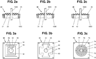
- FIG. 2 shows, not conclusive, different versions of parallel guide diaphragms.
- the FIGS. 2a to 2c show rotationally symmetric parallel guide membranes 20, 30, 40 in the section, which are identical in their structure except for the section profile of the parallel links 21, 31, 41.
- a rotationally symmetrical parallel guide membrane 20, 30, 40 is arranged between the load receiver, not shown, and the load cell 1000, wherein the fixed parallel leg 23, 33, 43 is fixed to the load cell 1000.
- the movable parallel leg 22, 32, 42 of the rotationally symmetric Parallel guide membrane 20, 30, 40 is rigidly connected to the power transmission linkage 1600.
- FIG. 3a shows in plan view a parallel guide membrane 50, the outer contour of the stationary parallel leg 53 corresponds to the cross section of the space orthogonal to the load direction of a weighing module.
- resilient parallel links 51 are formed. These connect the arranged in the center of the parallel guide diaphragm movable parallel leg 52 with the fixed parallel leg 53, wherein the fixed parallel leg 53 in the form of a closed frame encloses the parallel links 51 and the stationary parallel leg 52 in the extended plane of the parallel guide membrane 50.
- bores 54 are arranged, which serve for fixing the parallel guide diaphragm 50 to a load cell housing.
- the movable parallel leg 52 has a linkage bore 55, which serves to connect to the power transmission linkage of the corresponding load cell.
- FIG. 3b shows in plan view a parallel guide diaphragm 60 whose outer contour of the stationary parallel leg 63 corresponds to the cross section of the installation space orthogonal to the load direction of a weighing module.
- U-shaped and angular openings 66 orthogonal to the extended plane of the parallel guide membrane 60 By means of U-shaped and angular openings 66 orthogonal to the extended plane of the parallel guide membrane 60, a serial and parallel interconnection of a plurality of leaf springs to form several resilient parallel core 61 is formed.
- These connect the arranged in the middle of the parallel guide diaphragm 60 movable parallel leg 62 with the fixed parallel leg 63, wherein the fixed parallel leg 63 in the form of a closed frame, the parallel links 61 and the stationary parallel leg 62 in the extended plane of the parallel guide diaphragm 60 encloses.
- holes 64 are arranged, which serve to fix the parallel guide diaphragm 60 to a load cell housing.
- the movable parallel leg 62 has a linkage bore 65 which serves to connect to the power transmission linkage of the corresponding load cell.
- the apertures 66 need not necessarily have right-angled changes in direction, as are angles greater than 90 ° or less than 90 °, which correspond to a star-shaped arrangement of the parallel links 61. Similarly, instead of U-shaped openings 66 and M-shaped openings 66 are possible.
- FIG. 3c shows in plan view a parallel guide membrane 70, the outer contour of the stationary parallel leg 73 corresponds to the cross section of the installation space orthogonal to the load direction of a weighing module.
- Each annular spring segment 77 is connected by two webs to the next annular spring segment, wherein the two webs 78 are arranged between two annular spring segments 77 by 180 ° to each other and parallel to each two sides of the outer contour.
- the webs of adjacent annular spring segments 77 are each offset by 90 ° to each other in order to achieve the largest possible effective length of the parallel link 71.
- This connects the arranged in the center of the parallel guide diaphragm 70 movable parallel leg 72 with the fixed parallel leg 73, wherein the fixed parallel leg 73 in the form of a closed frame enclosing the parallel link 71 and the movable parallel leg 72 in the extended plane of the parallel guide diaphragm 70.
- bores 74 are arranged, which serve to fix the parallel guide diaphragm 70 to a load cell housing.
- the movable parallel leg 72 has a linkage bore 75 which serves to connect to the power transmission linkage of the corresponding load cell.
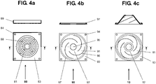
- FIG. 4a shows in plan view and in section a parallel guide membrane 80, which in their execution largely the in Figure 3c described in detail parallel guide membrane corresponds.
- the edge regions 89 of the stationary parallel leg 83 are bent at an angle at an angle in order to stiffen the stationary parallel leg 83.
- the webs 88 of the parallel armature 81 are aligned with the arranged in the fixed parallel leg 83 holes 84, ie diagonally to the square outer contour of the fixed parallel leg 83.
- the holes 84 are used for Fixing the fixed parallel leg 83 by fastening means to a load cell.
- FIG. 4b shows in plan view and in section a parallel guide membrane 90, the outer contour of the fixed parallel leg 93 corresponds to the cross section of the installation space orthogonal to the load direction of a weighing module.
- spiral perforations 96 orthogonal to the extended plane of the parallel guide membrane 90, helical, resilient parallel links 91 are formed.
- These connect the arranged in the middle of the parallel guide diaphragm movable parallel leg 92 with the fixed parallel leg 93, wherein the fixed parallel leg 93 in the form of a closed frame enclosing the parallel links 91 and the stationary parallel leg 92 in the extended plane of the parallel guide diaphragm 90.
- holes 94 are arranged, which serve for fixing the parallel guide diaphragm 90 to a load cell housing.
- the movable parallel leg 92 has a linkage bore 95 which serves to connect to the power transmission linkage of the corresponding load cell.
- a circumferential bead 97 is embossed to stiffen it.
- the inner edge of the bead 97 is arranged in the immediate vicinity of the ends of the spiral openings 96 facing away from the rod bore 95.
- the bead 97 need not be arranged concentrically to the rod bore 95.
- the bead 97 may be polygonal or interrupted in the extended plane of the parallel guide membrane 90.
- the stiffening of the stationary parallel leg 93 can also be effected by a rib which is produced by milling monolithic or as an additional part material- or non-positively connected to the stationary parallel leg 93.
- Figure 4c shows one with which in FIG. 4b illustrated parallel guide membrane almost identical parallel guide membrane 10, wherein the movable parallel leg 12 is arranged in a plane parallel to the extended plane of the stationary parallel leg 13, parallel plane.
- the spiral-shaped parallel links 11 strive thereby from the fixed parallel leg 13, tapered to the movable parallel leg 12 out.
- two parallel guide membranes necessary.
- illustrated parallel guide membrane 10 may have the frusto-conical structure of the first and second parallel guide membrane 10 in the same direction, therefore also be arranged in parallel with respect to their shape.
- the frusto-conical structure of the second parallel guide membrane 10 can also face in the opposite direction to the frusto-conical structure of the first parallel guide membrane 10. Furthermore, of course, an arrangement is possible in which the frusto-conical structures of the two parallel guide membranes 10 are arranged facing each other, so that the movable parallel leg 12 are arranged closer to each other than the fixed parallel leg thirteenth
- FIG. 5 is a weighing module 310 shown in perspective, the load cell 311 in the construction substantially in FIG. 1 corresponds to the load cell described. Unlike the in FIG. 1
- the weighing module 310 has an upper parallel guide part 330 arranged between the load receiver 350 and the load cell 311 and a lower parallel guide part 340 arranged on the side of the weighing cell remote from the load receiver 350
- Load cell 319 of the load cell 311 are monolithically connected.
- the upper parallel link 331 is folded in a plane containing the load direction. By in planes orthogonal to the load direction, the load cell housing 319 passing through, open on three sides of the load cell housing sections 335 of the upper parallel link 331 is formed.
- the cutting sequence is set so that in the load direction adjacent cuts 335 are respectively arranged starting from the opposite side. Cut extensions 336 at the bottom of cuts 335 and cutouts 337 on the same plane as cuts 335 on the load cell housing side not interspersed by the respective cut form a thin-film bonder 338, respectively. These interconnect the segments of parallel-link 331 formed by the cuts movable parallel leg 332 and with the load cell housing 319. An end plate 339 establishes the connection between the movable parallel leg 332 and the power transmission linkage 360.
- the lower parallel guide part 340 with its parallel link 341 is configured analogously to the upper parallel guide part 330.
- the parallel link 331 can also be designed to be elastic, so that no thin-layer bending bearings 338 are necessary.
- FIG. 6 shows a perspective view of a weighing module 410 with an arranged between the load pickup 450 and the load cell 411 upper parallel guide diaphragm 430, the upper fixed parallel leg 433 is fixed with fastening means 490 on the load cell housing 419 of the load cell 411.
- the lower stationary parallel leg 443 of the lower parallel guide diaphragm 440 is likewise fixed to the load cell housing 419.
- the upper Parallel guide diaphragm 430 corresponds to the one in FIG. 3a
- the upper movable parallel leg 432 is opposite to the load direction relative to the fixed parallel leg 433 arranged offset with the power transmission linkage 460 connected.
- the staggered, upper movable parallel leg 432 forms with the upper stationary parallel leg 433 and the upper parallel link 431 a pyramidal meandering parallel guide diaphragm 430.
- the same is true for the visible through the broken representation of the load cell housing 419 lower parallel guide 440 whose lower parallel link 441 through the lower movable parallel leg 442 is connected to the load cell 411 penetrating power transmission linkage 460.
- the lower movable parallel leg 442 need not necessarily be offset in the same direction - here against the load direction- as the upper movable parallel leg 432, but may also be offset in the load direction relative to the lower stationary parallel leg 443.
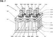
- FIG. 7 shows the perspective view of a device for weighing similar weighing samples 500 with a flat arrangement of weigh modules 510A, 510B, 510C, 510D, 510E, 510F.
- the weighing module 510A is rigidly connected to a receiving structure 501 by fasteners, not shown, such as bolts, and has a load cell 511A, the unillustrated internally-disposed spool of which is connected to a power linkage 560A.
- the load receiver 550A is mounted at the upper end of the power linkage 560A.
- the upper movable parallel leg 532A is mounted to the power linkage 560A.
- the upper parallel link 531A forms with the upper movable parallel leg 532A and with the upper fixed one Parallel leg the upper parallel guide diaphragm 530A.
- the upper parallel link 531A and the upper movable parallel leg 532 are analogous to those in FIG FIG. 1 described upper parallel guide diaphragm 130A configured.
- the upper parallel guide membranes 530A, 530B,... Of all weighing modules 510A, 510B, 510C, 510D, 510E, 510F designed and described analogously to the weighing module 510A are produced from a one-piece plate, the material-free regions being produced by milling, drilling, punching, laser cutting. or water jet cutting method, by spark erosion, photo etching and the like can be generated.
- all the upper parallel guide membranes 530A, 530B,... Have a common upper stationary parallel leg assembly 533.
- a completely identically manufactured second plate with the lower parallel guide membranes 540A, 540B,... Represents the lower stationary parallel leg assembly 543, the lower movable parallel legs 542A, 542B,... Through the lower parallel links 541A, 541B, fixed parallel leg assembly 543 are connected.
- the position of the lower movable parallel legs 542A, 542B, ... machined out of the plate must be exactly the same as the associated upper movable parallel legs 532A, 532B, ... in connection with the transmission links 560A, 560B, ... in order to provide parallel guidance Power transmission linkage 560A, 560B, ... is possible.
- the upper stationary parallel leg assembly 533 and the lower stationary parallel leg assembly 543 are rigidly interconnected by spacers 521.
- the two interconnected fixed parallel leg assemblies 533, 543 are rigidly fixed to the receiving structure 501 via the supports 507.
- the upper movable parallel leg 532A and the lower movable parallel leg 542A are connected to the power linkage 560A of the weigh module 510A, with the movable parallel legs 532A and 542A equidistant from the upper fixed parallel leg assembly 533 to the lower stationary parallel leg assembly 543.
- the illustration of the installation space 512A of the weighing module 510A clarifies the delimitation of the weighing module 510A with respect to the adjacent weighing modules as well as the delimitation of the upper parallel guide diaphragm 530A and the lower parallel guide diaphragm 540A in the parallel leg connections 533, 543 with respect to the adjacent parallel guide diaphragms.
- all of the power transmission linkages of the weigh modules 510A, 510B, 510C, 510D, 510E, 510F are respectively connected to their associated movable parallel legs.
- this arrangement is not limited to six weigh modules 510A, 510B, 510C, 510D, 510E, 510F. Any number of weighing modules can be arranged in a planar arrangement behind and next to one another, with the upper stationary parallel leg assembly 533 and the lower stationary parallel leg assembly 543 having to be adapted to the number of load cells.
- FIG. 8 shows the perspective view of a device for weighing Gleichgearteter weighing 600 with a planar arrangement according to the invention
- Weigh modules 610A, 610B, 610C, 610D, 610E, 610F the load cell housing are monolithically rigidly interconnected in a load cell housing 613 composite.
- This device for weighing gleichgearteter Weighing goods 600 has an upper stationary Parallelschenkelverbund 633 and a lower stationary Parallelschenkelverbund 643 in the construction largely the parallel leg joints in FIG. 7 correspond.
- Each weighing module 610A, 610B, ... also has a weighing cell 611A, 611B,... With associated load receiver 650A, 650B,.
- the illustration of the installation space 612A of the weighing module 610A illustrates the delimitation of the weighing module 610A from the adjacent weighing modules and the demarcation of the monolithically connected, stationary parallel legs.
- the upper parallel leg assembly is rigidly connected directly to the load cell housing assembly 613 via spacers 621.
- the power transmission linkages 660A, 660B, ... penetrate the load cells 611A, 611B, ... assigned to them in the load direction.
- the upper movable parallel legs and lower movable parallel legs associated with the weigh modules 610A, 610B, 610C, 610D, 610E, 610F are connected to the respective power transmission links 660A, 660B, 660C, 660D, 660E, 660F.
- this arrangement is not limited to six weigh modules 610A, 610B, 610C, 610D, 610E, 610F. Any number of weighing modules can be arranged in a planar arrangement behind and next to each other, with the upper fixed parallel leg assembly 633 and the lower fixed parallel leg assembly 643 having to be adapted to the number of load cells.
- FIG. 9 shows the perspective view of a device for weighing gleichgearteter weighing materials 700, each on a first Level 701 and arranged on a second level 702, flat arrangement of weighing modules as described previously in FIG. 8 has been described.
- the upper parallel leg assembly 733 and the lower parallel leg assembly 743 is not fixed by spacers and spacers on the load cell housing assembly 713 but directly connected rigidly thereto.
- the upper level 701 weigh modules 710A, 710B, 710C, 710D, 710E, 710F are rigidly interconnected by the load cell housing assembly 713.
- a circumferential collar 715 is formed on the load cell housing composite 713 which serves to connect the weighing modules of the plane 701 to the weighing modules of the plane 702 via a receiving structure which is not shown.
- the plane 701 is offset from the plane 702 so that the power transmission linkages 760U, 760V, 760W, 760X, 760Y, 760Z of the lower-level weighing modules 710U, 710V, 710W, 710X, 710Y, 710Z on the weighing modules 710A, 710B, 710C, 710D, 710E, 710F of the upper level 701 can be passed.
- the loaders 750U, ... of the lower level 702 are arranged in the same plane orthogonal to the load direction as the loaders 750A, ... of the upper level 701. To do so, the load cell housing 711 of the upper level 701 must have channels 717 through which the Power transmission linkages 760U, 760V, 760W, 760X, 760Y, 760Z the lower level 702 can be performed.
- each load cell has the same load and load transfer linkage load, the so-called preload.
- the preload difference between the upper level 701 and lower level 702 weigh modules 702 is balanced with a preload compensation weight 708, with a preload compensation weight 708 at each Power transmission linkage of each weighing module 710A, 710B, 710C, 710D, 710E, 710F upper level 701 is attached.
- this arrangement is not limited to six weighing modules 710A, 710B, 710C, 710D, 710E, 710F and 710U, 710V, 710W, 710X, 710Y, 710Z per level, respectively. It can be arranged in a planar arrangement in the manner shown behind and next to each other per level 701, 702 any number of weigh modules.
Priority Applications (5)
| Application Number | Priority Date | Filing Date | Title |
|---|---|---|---|
| PL05104522T PL1726926T3 (pl) | 2005-05-26 | 2005-05-26 | Prowadnica równoległa do kompaktowych systemów wagowych |
| EP05104522.7A EP1726926B1 (de) | 2005-05-26 | 2005-05-26 | Parallelführung für kompakte Wägesysteme |
| CN2006100848374A CN1869610B (zh) | 2005-05-26 | 2006-05-23 | 用于小型称重系统的平行导向装置 |
| JP2006144844A JP4840766B2 (ja) | 2005-05-26 | 2006-05-25 | 小型秤量システムのための平行案内機構 |
| US11/441,005 US7429705B2 (en) | 2005-05-26 | 2006-05-26 | Parallel-guiding mechanism for compact weighing system |
Applications Claiming Priority (1)
| Application Number | Priority Date | Filing Date | Title |
|---|---|---|---|
| EP05104522.7A EP1726926B1 (de) | 2005-05-26 | 2005-05-26 | Parallelführung für kompakte Wägesysteme |
Publications (2)
| Publication Number | Publication Date |
|---|---|
| EP1726926A1 EP1726926A1 (de) | 2006-11-29 |
| EP1726926B1 true EP1726926B1 (de) | 2017-03-22 |
Family
ID=34980120
Family Applications (1)
| Application Number | Title | Priority Date | Filing Date |
|---|---|---|---|
| EP05104522.7A Revoked EP1726926B1 (de) | 2005-05-26 | 2005-05-26 | Parallelführung für kompakte Wägesysteme |
Country Status (5)
| Country | Link |
|---|---|
| US (1) | US7429705B2 (pl) |
| EP (1) | EP1726926B1 (pl) |
| JP (1) | JP4840766B2 (pl) |
| CN (1) | CN1869610B (pl) |
| PL (1) | PL1726926T3 (pl) |
Cited By (1)
| Publication number | Priority date | Publication date | Assignee | Title |
|---|---|---|---|---|
| EP4009013A1 (de) | 2020-12-04 | 2022-06-08 | Mettler-Toledo GmbH | Strukturkörper eines wägesensors |
Families Citing this family (24)
| Publication number | Priority date | Publication date | Assignee | Title |
|---|---|---|---|---|
| EP1871274B1 (en) | 2005-03-07 | 2019-05-08 | Align Technology, Inc. | Wrinkled dental aligner |
| PL1701144T3 (pl) * | 2005-03-10 | 2012-06-29 | Mettler Toledo Gmbh | Urządzenie do ważenia jednakowego rodzaju ważonych towarów |
| US20060275731A1 (en) | 2005-04-29 | 2006-12-07 | Orthoclear Holdings, Inc. | Treatment of teeth by aligners |
| PL1726926T3 (pl) * | 2005-05-26 | 2017-08-31 | Mettler-Toledo Gmbh | Prowadnica równoległa do kompaktowych systemów wagowych |
| DE102005025534C5 (de) * | 2005-06-03 | 2012-08-16 | Sartorius Weighing Technology Gmbh | Wägeanlage |
| CN2874442Y (zh) * | 2006-01-24 | 2007-02-28 | 中山市创源电子有限公司 | 一种传感器及装有这种传感器的电子秤 |
| EP1873504A1 (de) * | 2006-06-28 | 2008-01-02 | Mettler-Toledo AG | Kalibriergewichtsanordnung für eine elektronische Waage |
| EP1925919A1 (de) | 2006-11-24 | 2008-05-28 | Mettler-Toledo AG | Wägezelle |
| JP4859659B2 (ja) * | 2006-12-26 | 2012-01-25 | 大和製衡株式会社 | マルチ計量槽の計量システム |
| EP2153185B1 (de) * | 2007-06-01 | 2017-04-19 | Mettler-Toledo GmbH | Justierbare parallelführung für kompakte gravimetrische messinstrumente |
| US8926171B2 (en) * | 2009-04-29 | 2015-01-06 | Waters Technologies Corporation | Simultaneous differential thermal analysis system |
| PL2434264T3 (pl) | 2010-09-24 | 2014-08-29 | Mettler Toledo Gmbh | Urządzenie przenoszące siłę ze sprzęgalnym odważnikiem kalibracyjnym |
| PL2533024T3 (pl) | 2011-06-09 | 2014-08-29 | Mettler Toledo Gmbh | Urządzenie przenoszące siłę ze sprzęgalnym odważnikiem kalibracyjnym |
| EP2615433B1 (de) * | 2012-01-11 | 2015-06-24 | Mettler-Toledo AG | Vorrichtung und Verfahren zur Justierung des Eckenlastfehlers einer Parallelführung |
| US9027380B2 (en) | 2012-03-06 | 2015-05-12 | Mettler-Toledo Ag | Force-transmitting mechanism with a calibration weight that can be coupled and uncoupled |
| CN104724638B (zh) * | 2015-04-01 | 2017-09-08 | 厦门理工学院 | 叉车称重装置和叉车自动称重的方法 |
| CN107036696A (zh) * | 2016-02-03 | 2017-08-11 | 梅特勒-托利多(常州)精密仪器有限公司 | 称重模块 |
| WO2019123440A1 (en) * | 2017-12-24 | 2019-06-27 | Shekel Scales (2008) Ltd | Planar load cell assembly |
| JP2021526651A (ja) | 2018-05-16 | 2021-10-07 | シェケル スケールズ(2008)リミテッド | 計量ロードセルおよびそれらを棚において利用する構成 |
| IL279075B1 (en) * | 2018-06-06 | 2024-01-01 | Shekel Scales 2008 Ltd | Systems and methods for weighing products on a shelf |
| WO2020003221A1 (en) | 2018-06-28 | 2020-01-02 | Shekel Scales (2008) Ltd | Systems and methods for weighing products on a shelf |
| EP3708978B1 (de) | 2019-03-11 | 2023-05-03 | Mettler-Toledo GmbH | Kompaktes direktmesssystem |
| CN113567038A (zh) * | 2021-07-13 | 2021-10-29 | 中山市富茂密封科技有限公司 | 压力感测金属膜片、压力感测膜片组及压力表 |
| CN113295247B (zh) * | 2021-07-28 | 2021-10-12 | 深圳市同富信息技术有限公司 | 一种基于物联网的物料自动称量装置 |
Citations (10)
| Publication number | Priority date | Publication date | Assignee | Title |
|---|---|---|---|---|
| DE1194167B (de) | 1961-09-08 | 1965-06-03 | Philips Nv | Wiegevorrichtung |
| GB2124396A (en) * | 1982-07-16 | 1984-02-15 | Mettler Instrumente Ag | Weighing cells |
| US4433742A (en) | 1981-05-19 | 1984-02-28 | Setra Systems, Inc. | Linear motion linkage |
| US4467883A (en) | 1981-12-22 | 1984-08-28 | Mettler Instrumente Ag | Weighing apparatus including parallel guidance members having integral guide arms |
| US4509610A (en) | 1981-10-28 | 1985-04-09 | Yamato Scale Company, Limited | Weighing device of load cell type |
| US4585083A (en) | 1983-11-01 | 1986-04-29 | Shinko Denshi Company Ltd. | Mechanism for detecting load |
| JPH07243922A (ja) | 1994-03-03 | 1995-09-19 | Yamato Scale Co Ltd | 複合ロードセル |
| US5646375A (en) | 1995-01-23 | 1997-07-08 | Tedea-Huntleigh International Ltd. | Symmetrical load cells for use in conjuction with rotary machines |
| JPH1183645A (ja) | 1997-09-10 | 1999-03-26 | Kawatetsu Advantec Kk | ロードセル |
| DE29917940U1 (de) | 1999-10-12 | 2000-01-05 | Fraunhofer Ges Forschung | Vorrichtung zur gravimetrischen Prüfung von Mehrkanalpipetten |
Family Cites Families (22)
| Publication number | Priority date | Publication date | Assignee | Title |
|---|---|---|---|---|
| US2969228A (en) * | 1958-04-02 | 1961-01-24 | Erhard Mettler | Spring balance |
| US3135112A (en) * | 1960-09-06 | 1964-06-02 | Baldwin Lima Hamilton Corp | Safety-load control of parallelogram type of load cell |
| US3161046A (en) * | 1961-06-13 | 1964-12-15 | Baldwin Lima Hamilton Corp | Load cell |
| US3590933A (en) * | 1968-12-16 | 1971-07-06 | Driver Southall | Weigh beams |
| CH593481A5 (pl) | 1975-11-18 | 1977-12-15 | Mettler Instrumente Ag | |
| CH638894A5 (de) | 1979-08-28 | 1983-10-14 | Mettler Instrumente Ag | Elektrische waage. |
| JPS5980725A (ja) * | 1982-10-28 | 1984-05-10 | Kawasaki Steel Corp | 磁気特性に優れた無方向性珪素鋼薄帯の製造方法 |
| JPS6225710A (ja) * | 1985-07-26 | 1987-02-03 | Matsushita Electric Ind Co Ltd | 光合波・分波器 |
| JPS6240531A (ja) * | 1985-08-16 | 1987-02-21 | Fujitsu Ltd | 半導体集積回路 |
| JPS6421327A (en) | 1987-07-17 | 1989-01-24 | Fuji Electric Co Ltd | Rubbing monitoring apparatus |
| US4838371A (en) * | 1988-01-22 | 1989-06-13 | Rupprecht & Patashnick Co., Inc. | Constrained linear motion inertial balance |
| DE3802153A1 (de) * | 1988-01-26 | 1989-08-03 | Soehnle Waagen Gmbh & Co | Kraftmesselement fuer eine waage |
| JPH01212327A (ja) | 1988-02-19 | 1989-08-25 | Ishida Scales Mfg Co Ltd | ロードセルおよびその製造方法 |
| US4848493A (en) * | 1988-10-20 | 1989-07-18 | Revere Corporation Of America | Load sensing structure for weighing apparatus |
| US5880410A (en) * | 1995-01-26 | 1999-03-09 | Tedea Huntleigh International, Ltd. | Load cells with integral damping |
| DE19729623B4 (de) * | 1997-07-10 | 2004-10-07 | Mettler-Toledo Gmbh | Anordnung zum Befestigen einer Parallelogrammführung in einer Kraftmeßvorrichtung |
| US6634235B2 (en) * | 2000-11-30 | 2003-10-21 | Alps Electric Co., Ltd. | Load sensor with strain-sensing elements |
| DE10242118B4 (de) * | 2002-04-23 | 2014-06-26 | Robert Bosch Gmbh | Vorrichtung zum Wiegen von pharmazeutischen Behältnissen |
| CN2736744Y (zh) * | 2004-09-13 | 2005-10-26 | 吴科杰 | 称重传感器模块 |
| EP1698872B1 (de) * | 2005-03-02 | 2007-10-10 | Mettler-Toledo AG | Vorrichtung zum Wiegen gleichgearteter Wägegüter |
| PL1701144T3 (pl) * | 2005-03-10 | 2012-06-29 | Mettler Toledo Gmbh | Urządzenie do ważenia jednakowego rodzaju ważonych towarów |
| PL1726926T3 (pl) * | 2005-05-26 | 2017-08-31 | Mettler-Toledo Gmbh | Prowadnica równoległa do kompaktowych systemów wagowych |
-
2005
- 2005-05-26 PL PL05104522T patent/PL1726926T3/pl unknown
- 2005-05-26 EP EP05104522.7A patent/EP1726926B1/de not_active Revoked
-
2006
- 2006-05-23 CN CN2006100848374A patent/CN1869610B/zh active Active
- 2006-05-25 JP JP2006144844A patent/JP4840766B2/ja active Active
- 2006-05-26 US US11/441,005 patent/US7429705B2/en active Active
Patent Citations (13)
| Publication number | Priority date | Publication date | Assignee | Title |
|---|---|---|---|---|
| DE1194167B (de) | 1961-09-08 | 1965-06-03 | Philips Nv | Wiegevorrichtung |
| US4433742A (en) | 1981-05-19 | 1984-02-28 | Setra Systems, Inc. | Linear motion linkage |
| US4509610A (en) | 1981-10-28 | 1985-04-09 | Yamato Scale Company, Limited | Weighing device of load cell type |
| US4467883A (en) | 1981-12-22 | 1984-08-28 | Mettler Instrumente Ag | Weighing apparatus including parallel guidance members having integral guide arms |
| GB2124396B (en) * | 1982-07-16 | 1986-09-24 | Mettler Instrumente Ag | Weighing cells |
| GB2124396A (en) * | 1982-07-16 | 1984-02-15 | Mettler Instrumente Ag | Weighing cells |
| US4497386A (en) | 1982-07-16 | 1985-02-05 | Mettler Instrumente Ag | Weighing apparatus including improved force-transmitting lever means |
| US4585083A (en) | 1983-11-01 | 1986-04-29 | Shinko Denshi Company Ltd. | Mechanism for detecting load |
| DE3439325C2 (pl) | 1983-11-01 | 1987-04-23 | Shinko Denshi Co. Ltd., Tokio/Tokyo, Jp | |
| JPH07243922A (ja) | 1994-03-03 | 1995-09-19 | Yamato Scale Co Ltd | 複合ロードセル |
| US5646375A (en) | 1995-01-23 | 1997-07-08 | Tedea-Huntleigh International Ltd. | Symmetrical load cells for use in conjuction with rotary machines |
| JPH1183645A (ja) | 1997-09-10 | 1999-03-26 | Kawatetsu Advantec Kk | ロードセル |
| DE29917940U1 (de) | 1999-10-12 | 2000-01-05 | Fraunhofer Ges Forschung | Vorrichtung zur gravimetrischen Prüfung von Mehrkanalpipetten |
Non-Patent Citations (4)
| Title |
|---|
| DRECHSEL D. ET AL: "Wäge-, Abführ- und Verpackungsprozesse", 2001, OLDENBOURG INDUSTRIEVERLAGE GMBH, article "Wägetechnik", pages: 30, XP055449016 |
| MANFRED KOCHSIEK: "Handbuch des Wägens", 1989, FRIEDR. VIEWEG & SON, pages: 122 - 127, XP055449025 |
| PROF. DR.-LNG. EM. SIEGFRIED HILDEBRAND: "Feinmechanische Bauelemente", 1967, VEB VERLAG TECHNIK, Berlin, article "Speicherelemente", pages: 264 - 275,412-414, XP055448998 |
| WERNER KRAUSE: "Konstruktionselemente der Feinmechanik", 1989, CARL HANSER VERLAG, München, Wien, article "Lager und Führungen", pages: 422, XP055449094 |
Cited By (2)
| Publication number | Priority date | Publication date | Assignee | Title |
|---|---|---|---|---|
| EP4009013A1 (de) | 2020-12-04 | 2022-06-08 | Mettler-Toledo GmbH | Strukturkörper eines wägesensors |
| WO2022117801A1 (de) | 2020-12-04 | 2022-06-09 | Mettler-Toledo Gmbh | Strukturkörper eines wägesensors |
Also Published As
| Publication number | Publication date |
|---|---|
| CN1869610A (zh) | 2006-11-29 |
| JP2006329989A (ja) | 2006-12-07 |
| PL1726926T3 (pl) | 2017-08-31 |
| EP1726926A1 (de) | 2006-11-29 |
| CN1869610B (zh) | 2010-09-01 |
| US20060266562A1 (en) | 2006-11-30 |
| JP4840766B2 (ja) | 2011-12-21 |
| US7429705B2 (en) | 2008-09-30 |
Similar Documents
| Publication | Publication Date | Title |
|---|---|---|
| EP1726926B1 (de) | Parallelführung für kompakte Wägesysteme | |
| DE3590262C2 (pl) | ||
| EP2549253B1 (de) | Meßkörper, Kraftmeßsensor und Meßanordnung zur Messung von Kräften | |
| EP2032954B1 (de) | Kalibriergewichtsanordnung für eine elektronische waage | |
| EP1701144B9 (de) | Vorrichtung zum Wiegen gleichgearteter Wägegüter | |
| EP1754030B1 (de) | Überlastsicherung für ein kraftmesselement | |
| EP1924828B1 (de) | Hebelgetriebe, insbesondere für einen wägeaufnehmer einer nach dem prinzip der elektromagnetischen kraftkompensation arbeitenden waage | |
| EP0288985B1 (de) | Biegering-Wägezelle | |
| DE2946868A1 (de) | Druckkraftmesseinrichtung mit ringfoermigem verformungskoerper | |
| CH667734A5 (de) | Kraftwandler. | |
| EP1672335B1 (de) | Wägemodul mit einer positionspräzisen Überlastschutzvorrichtung | |
| EP3491355B1 (de) | Kraftmesseinrichtung zur mehrachsigen erfassung einwirkender kräfte und momente | |
| EP0310758B1 (de) | Elektromechanische Waage | |
| EP2062014B1 (de) | Wägevorrichtung | |
| DE19743832C2 (de) | Vorrichtung zur Ermittlung der Lage des Schwerpunktes eines Prüfkörpers | |
| EP0483912B1 (de) | Scheibenförmiger Scherkraft-Messwertaufnehmer für eine Wägezelle | |
| WO2018024519A1 (de) | Ein- oder mehrachsige kraftmesseinrichtung mit kurzer verformungszone | |
| WO2007033956A1 (de) | Mehrfachwägevorrichtung mit einer kalibriervorrichtung | |
| EP2610595B1 (de) | Wägebrücke | |
| DE2946175C2 (pl) | ||
| DE102008056714B4 (de) | Elektronische Waage | |
| DE10055933A1 (de) | Aufnehmer zum Messen von Belastungen | |
| EP3650825B1 (de) | Betriebskraftmessung bei einem mechanischen bauelement | |
| DE102018113771B4 (de) | Messvorrichtung zur Ermittlung von Zug- und Druckkräften, insbesondere Wägezelle | |
| EP2374594B1 (de) | Spritzgiessmaschine |
Legal Events
| Date | Code | Title | Description |
|---|---|---|---|
| PUAI | Public reference made under article 153(3) epc to a published international application that has entered the european phase |
Free format text: ORIGINAL CODE: 0009012 |
|
| AK | Designated contracting states |
Kind code of ref document: A1 Designated state(s): AT BE BG CH CY CZ DE DK EE ES FI FR GB GR HU IE IS IT LI LT LU MC NL PL PT RO SE SI SK TR |
|
| AX | Request for extension of the european patent |
Extension state: AL BA HR LV MK YU |
|
| 17P | Request for examination filed |
Effective date: 20070315 |
|
| AKX | Designation fees paid |
Designated state(s): AT BE BG CH CY CZ DE DK EE ES FI FR GB GR HU IE IS IT LI LT LU MC NL PL PT RO SE SI SK TR |
|
| 17Q | First examination report despatched |
Effective date: 20100409 |
|
| RAP1 | Party data changed (applicant data changed or rights of an application transferred) |
Owner name: METTLER-TOLEDO GMBH |
|
| GRAP | Despatch of communication of intention to grant a patent |
Free format text: ORIGINAL CODE: EPIDOSNIGR1 |
|
| INTG | Intention to grant announced |
Effective date: 20161031 |
|
| STAA | Information on the status of an ep patent application or granted ep patent |
Free format text: STATUS: GRANT OF PATENT IS INTENDED |
|
| GRAS | Grant fee paid |
Free format text: ORIGINAL CODE: EPIDOSNIGR3 |
|
| GRAA | (expected) grant |
Free format text: ORIGINAL CODE: 0009210 |
|
| STAA | Information on the status of an ep patent application or granted ep patent |
Free format text: STATUS: THE PATENT HAS BEEN GRANTED |
|
| AK | Designated contracting states |
Kind code of ref document: B1 Designated state(s): AT BE BG CH CY CZ DE DK EE ES FI FR GB GR HU IE IS IT LI LT LU MC NL PL PT RO SE SI SK TR |
|
| REG | Reference to a national code |
Ref country code: GB Ref legal event code: FG4D Free format text: NOT ENGLISH |
|
| REG | Reference to a national code |
Ref country code: CH Ref legal event code: EP |
|
| REG | Reference to a national code |
Ref country code: AT Ref legal event code: REF Ref document number: 878253 Country of ref document: AT Kind code of ref document: T Effective date: 20170415 |
|
| REG | Reference to a national code |
Ref country code: IE Ref legal event code: FG4D Free format text: LANGUAGE OF EP DOCUMENT: GERMAN |
|
| REG | Reference to a national code |
Ref country code: DE Ref legal event code: R096 Ref document number: 502005015541 Country of ref document: DE |
|
| REG | Reference to a national code |
Ref country code: NL Ref legal event code: MP Effective date: 20170322 |
|
| PG25 | Lapsed in a contracting state [announced via postgrant information from national office to epo] |
Ref country code: LT Free format text: LAPSE BECAUSE OF FAILURE TO SUBMIT A TRANSLATION OF THE DESCRIPTION OR TO PAY THE FEE WITHIN THE PRESCRIBED TIME-LIMIT Effective date: 20170322 Ref country code: GR Free format text: LAPSE BECAUSE OF FAILURE TO SUBMIT A TRANSLATION OF THE DESCRIPTION OR TO PAY THE FEE WITHIN THE PRESCRIBED TIME-LIMIT Effective date: 20170623 Ref country code: FI Free format text: LAPSE BECAUSE OF FAILURE TO SUBMIT A TRANSLATION OF THE DESCRIPTION OR TO PAY THE FEE WITHIN THE PRESCRIBED TIME-LIMIT Effective date: 20170322 |
|
| REG | Reference to a national code |
Ref country code: LT Ref legal event code: MG4D |
|
| PG25 | Lapsed in a contracting state [announced via postgrant information from national office to epo] |
Ref country code: SE Free format text: LAPSE BECAUSE OF FAILURE TO SUBMIT A TRANSLATION OF THE DESCRIPTION OR TO PAY THE FEE WITHIN THE PRESCRIBED TIME-LIMIT Effective date: 20170322 Ref country code: BG Free format text: LAPSE BECAUSE OF FAILURE TO SUBMIT A TRANSLATION OF THE DESCRIPTION OR TO PAY THE FEE WITHIN THE PRESCRIBED TIME-LIMIT Effective date: 20170622 Ref country code: LU Free format text: LAPSE BECAUSE OF NON-PAYMENT OF DUE FEES Effective date: 20170531 |
|
| PG25 | Lapsed in a contracting state [announced via postgrant information from national office to epo] |
Ref country code: NL Free format text: LAPSE BECAUSE OF FAILURE TO SUBMIT A TRANSLATION OF THE DESCRIPTION OR TO PAY THE FEE WITHIN THE PRESCRIBED TIME-LIMIT Effective date: 20170322 |
|
| PG25 | Lapsed in a contracting state [announced via postgrant information from national office to epo] |
Ref country code: SK Free format text: LAPSE BECAUSE OF FAILURE TO SUBMIT A TRANSLATION OF THE DESCRIPTION OR TO PAY THE FEE WITHIN THE PRESCRIBED TIME-LIMIT Effective date: 20170322 Ref country code: IT Free format text: LAPSE BECAUSE OF FAILURE TO SUBMIT A TRANSLATION OF THE DESCRIPTION OR TO PAY THE FEE WITHIN THE PRESCRIBED TIME-LIMIT Effective date: 20170322 Ref country code: RO Free format text: LAPSE BECAUSE OF FAILURE TO SUBMIT A TRANSLATION OF THE DESCRIPTION OR TO PAY THE FEE WITHIN THE PRESCRIBED TIME-LIMIT Effective date: 20170322 Ref country code: ES Free format text: LAPSE BECAUSE OF FAILURE TO SUBMIT A TRANSLATION OF THE DESCRIPTION OR TO PAY THE FEE WITHIN THE PRESCRIBED TIME-LIMIT Effective date: 20170322 Ref country code: EE Free format text: LAPSE BECAUSE OF FAILURE TO SUBMIT A TRANSLATION OF THE DESCRIPTION OR TO PAY THE FEE WITHIN THE PRESCRIBED TIME-LIMIT Effective date: 20170322 Ref country code: CZ Free format text: LAPSE BECAUSE OF FAILURE TO SUBMIT A TRANSLATION OF THE DESCRIPTION OR TO PAY THE FEE WITHIN THE PRESCRIBED TIME-LIMIT Effective date: 20170322 |
|
| PG25 | Lapsed in a contracting state [announced via postgrant information from national office to epo] |
Ref country code: IS Free format text: LAPSE BECAUSE OF FAILURE TO SUBMIT A TRANSLATION OF THE DESCRIPTION OR TO PAY THE FEE WITHIN THE PRESCRIBED TIME-LIMIT Effective date: 20170722 Ref country code: PT Free format text: LAPSE BECAUSE OF FAILURE TO SUBMIT A TRANSLATION OF THE DESCRIPTION OR TO PAY THE FEE WITHIN THE PRESCRIBED TIME-LIMIT Effective date: 20170724 |
|
| REG | Reference to a national code |
Ref country code: DE Ref legal event code: R026 Ref document number: 502005015541 Country of ref document: DE |
|
| PLBI | Opposition filed |
Free format text: ORIGINAL CODE: 0009260 |
|
| PLAX | Notice of opposition and request to file observation + time limit sent |
Free format text: ORIGINAL CODE: EPIDOSNOBS2 |
|
| PG25 | Lapsed in a contracting state [announced via postgrant information from national office to epo] |
Ref country code: DK Free format text: LAPSE BECAUSE OF FAILURE TO SUBMIT A TRANSLATION OF THE DESCRIPTION OR TO PAY THE FEE WITHIN THE PRESCRIBED TIME-LIMIT Effective date: 20170322 Ref country code: MC Free format text: LAPSE BECAUSE OF FAILURE TO SUBMIT A TRANSLATION OF THE DESCRIPTION OR TO PAY THE FEE WITHIN THE PRESCRIBED TIME-LIMIT Effective date: 20170322 |
|
| 26 | Opposition filed |
Opponent name: WIPOTEC WIEGE- UND POSITIONIERSYSTEME GMBH Effective date: 20171222 |
|
| REG | Reference to a national code |
Ref country code: IE Ref legal event code: MM4A |
|
| GBPC | Gb: european patent ceased through non-payment of renewal fee |
Effective date: 20170622 |
|
| PG25 | Lapsed in a contracting state [announced via postgrant information from national office to epo] |
Ref country code: SI Free format text: LAPSE BECAUSE OF FAILURE TO SUBMIT A TRANSLATION OF THE DESCRIPTION OR TO PAY THE FEE WITHIN THE PRESCRIBED TIME-LIMIT Effective date: 20170322 |
|
| REG | Reference to a national code |
Ref country code: FR Ref legal event code: ST Effective date: 20180131 |
|
| PG25 | Lapsed in a contracting state [announced via postgrant information from national office to epo] |
Ref country code: LU Free format text: LAPSE BECAUSE OF NON-PAYMENT OF DUE FEES Effective date: 20170526 |
|
| REG | Reference to a national code |
Ref country code: BE Ref legal event code: MM Effective date: 20170531 |
|
| PG25 | Lapsed in a contracting state [announced via postgrant information from national office to epo] |
Ref country code: IE Free format text: LAPSE BECAUSE OF NON-PAYMENT OF DUE FEES Effective date: 20170526 Ref country code: GB Free format text: LAPSE BECAUSE OF NON-PAYMENT OF DUE FEES Effective date: 20170622 |
|
| PG25 | Lapsed in a contracting state [announced via postgrant information from national office to epo] |
Ref country code: FR Free format text: LAPSE BECAUSE OF NON-PAYMENT OF DUE FEES Effective date: 20170531 |
|
| PLBB | Reply of patent proprietor to notice(s) of opposition received |
Free format text: ORIGINAL CODE: EPIDOSNOBS3 |
|
| REG | Reference to a national code |
Ref country code: AT Ref legal event code: MM01 Ref document number: 878253 Country of ref document: AT Kind code of ref document: T Effective date: 20170526 |
|
| PG25 | Lapsed in a contracting state [announced via postgrant information from national office to epo] |
Ref country code: AT Free format text: LAPSE BECAUSE OF NON-PAYMENT OF DUE FEES Effective date: 20170526 Ref country code: BE Free format text: LAPSE BECAUSE OF NON-PAYMENT OF DUE FEES Effective date: 20170531 |
|
| PG25 | Lapsed in a contracting state [announced via postgrant information from national office to epo] |
Ref country code: HU Free format text: LAPSE BECAUSE OF FAILURE TO SUBMIT A TRANSLATION OF THE DESCRIPTION OR TO PAY THE FEE WITHIN THE PRESCRIBED TIME-LIMIT; INVALID AB INITIO Effective date: 20050526 |
|
| PG25 | Lapsed in a contracting state [announced via postgrant information from national office to epo] |
Ref country code: CY Free format text: LAPSE BECAUSE OF NON-PAYMENT OF DUE FEES Effective date: 20170322 |
|
| RDAF | Communication despatched that patent is revoked |
Free format text: ORIGINAL CODE: EPIDOSNREV1 |
|
| APBM | Appeal reference recorded |
Free format text: ORIGINAL CODE: EPIDOSNREFNO |
|
| APBP | Date of receipt of notice of appeal recorded |
Free format text: ORIGINAL CODE: EPIDOSNNOA2O |
|
| APAH | Appeal reference modified |
Free format text: ORIGINAL CODE: EPIDOSCREFNO |
|
| PG25 | Lapsed in a contracting state [announced via postgrant information from national office to epo] |
Ref country code: TR Free format text: LAPSE BECAUSE OF FAILURE TO SUBMIT A TRANSLATION OF THE DESCRIPTION OR TO PAY THE FEE WITHIN THE PRESCRIBED TIME-LIMIT Effective date: 20170322 |
|
| APBQ | Date of receipt of statement of grounds of appeal recorded |
Free format text: ORIGINAL CODE: EPIDOSNNOA3O |
|
| REG | Reference to a national code |
Ref country code: DE Ref legal event code: R103 Ref document number: 502005015541 Country of ref document: DE Ref country code: DE Ref legal event code: R064 Ref document number: 502005015541 Country of ref document: DE |
|
| APBU | Appeal procedure closed |
Free format text: ORIGINAL CODE: EPIDOSNNOA9O |
|
| PGFP | Annual fee paid to national office [announced via postgrant information from national office to epo] |
Ref country code: DE Payment date: 20220527 Year of fee payment: 18 |
|
| RDAG | Patent revoked |
Free format text: ORIGINAL CODE: 0009271 |
|
| STAA | Information on the status of an ep patent application or granted ep patent |
Free format text: STATUS: PATENT REVOKED |
|
| PGFP | Annual fee paid to national office [announced via postgrant information from national office to epo] |
Ref country code: PL Payment date: 20220517 Year of fee payment: 18 Ref country code: CH Payment date: 20220520 Year of fee payment: 18 |
|
| REG | Reference to a national code |
Ref country code: CH Ref legal event code: PL |
|
| REG | Reference to a national code |
Ref country code: FI Ref legal event code: MGE |
|
| 27W | Patent revoked |
Effective date: 20220527 |
|
| REG | Reference to a national code |
Ref country code: AT Ref legal event code: MA03 Ref document number: 878253 Country of ref document: AT Kind code of ref document: T Effective date: 20220527 |