EP1726235B1 - Dispositif de conditionnement et d'application - Google Patents
Dispositif de conditionnement et d'application Download PDFInfo
- Publication number
- EP1726235B1 EP1726235B1 EP06300519.3A EP06300519A EP1726235B1 EP 1726235 B1 EP1726235 B1 EP 1726235B1 EP 06300519 A EP06300519 A EP 06300519A EP 1726235 B1 EP1726235 B1 EP 1726235B1
- Authority
- EP
- European Patent Office
- Prior art keywords
- applicator element
- cavity
- applicator
- branches
- product
- Prior art date
- Legal status (The legal status is an assumption and is not a legal conclusion. Google has not performed a legal analysis and makes no representation as to the accuracy of the status listed.)
- Not-in-force
Links
Images


Classifications
-
- A—HUMAN NECESSITIES
- A45—HAND OR TRAVELLING ARTICLES
- A45D—HAIRDRESSING OR SHAVING EQUIPMENT; EQUIPMENT FOR COSMETICS OR COSMETIC TREATMENTS, e.g. FOR MANICURING OR PEDICURING
- A45D40/00—Casings or accessories specially adapted for storing or handling solid or pasty toiletry or cosmetic substances, e.g. shaving soaps or lipsticks
- A45D40/26—Appliances specially adapted for applying pasty paint, e.g. using roller, using a ball
- A45D40/262—Appliances specially adapted for applying pasty paint, e.g. using roller, using a ball using a brush or the like
- A45D40/265—Appliances specially adapted for applying pasty paint, e.g. using roller, using a ball using a brush or the like connected to the cap of the container
- A45D40/267—Appliances specially adapted for applying pasty paint, e.g. using roller, using a ball using a brush or the like connected to the cap of the container comprising a wiper
Definitions
- the present invention relates to the applicators of cosmetic products, including care products.
- the European patent application EP 0 875 169-A1 discloses an applicator having an applicator member having a flocked foam block at one end. The lateral surface of the applicator member is striated.
- the European patent EP 0 824 329-B1 discloses a packaging and application device comprising a wiper member consisting at least partially of a cellular material.
- the applicator member is in the form of a hollow body having a cavity adapted to house a reserve of product.
- the French patent application FR 2,771,077 also discloses a packaging device and application comprising a wiper member formed at least in part by a porous material elastically deformable.
- the applicator member has slots that are sufficiently narrow so that the wiper member can hardly reach them, making it possible to preserve a reserve of product inside the applicator member after spinning. .
- the European patent application EP 0 693 263-A1 discloses an applicator comprising a rod at the end of which is disposed a compound application member a loop whose two ends are connected separately to the rod. Such an applicator is more particularly intended for the application of nail polish and the rod has a flexibility close to that of the applicator member.
- the present invention aims to provide a new applicator to achieve a neat makeup, comfortable to use, and able to store a relatively large amount of product.
- the subject of the invention is a packaging and application device as defined in claim 1.
- the application element passes through a wiper member between the moment when it leaving the product and the moment when the composition is applied, the absence of deformation of the cavity can result from the use of a sufficient wiper member flexible to not unduly deform the application element, for example a wiper member having a corrugated lip, or may result from a particular setting of an adjustable wiper member.
- the absence of deformation of the cavity can result from a wiper member that is sufficiently flexible to not unduly stress the application element, for example a wiper member having a corrugated lip, or a particular setting of the wiper member when it is adjustable.
- At least one of the branches may have a flocking coating on at least half of its length, for example, better along its entire length.
- the cavity may be completely or not filled with product before application.
- the product present in the cavity can come directly into contact with the surface to be treated.
- the product may be liquid, being for example intended for application to the lips, skin, or integuments.
- the product may also be solid or powdery, being for example in the form of a loaf, to moisten or not to allow the removal of the product.
- the product is packaged in a container provided with a wiper member, which is for example made of a non-cellular material, for example an elastomer, which may allow to leave more product in the cavity.
- the wiper member comprises for example one or more slots.
- the cavity can provide a reserve of product providing additional autonomy to the application element or easier to deposit a larger amount of product, to enhance a makeup effect, for example the color or brightness of a product applied to the lips, for example the gloss of a lip gloss.
- the application can still take place on the integuments, in particular the eyelashes and / or the eyebrows, for the care or makeup of these.
- At least one of the branches may have, in cross section, an at least partially rounded shape. Such a shape can improve application comfort and reduce the risk that movement of the applicator element over the area to be removed removes previously applied product.
- At least one of the branches may for example have in cross section a circular, oval or elliptical shape.
- at least one of the branches may have a substantially triangular, square or rectangular cross-sectional shape.
- the branches may each have a substantially rectilinear longitudinal axis or curvilinear, possibly corrugated.
- At least one of the branches may have a dimension, in cross section, greater than the width of the cavity, for example a width or height greater than the width of the cavity.
- the cavity may have a maximum width greater than the diameter of the rod.
- the application element may be devoid of metal, which allows for example its passage in a microwave oven.
- the shape of the application element may depend in particular on the region of the body or face on which the product is to be applied.
- the cavity may advantageously extend substantially parallel to a plane forming a non-zero angle with the longitudinal axis of a rod to which the applicator element is connected. At least a portion of the applicator element can thus be elongated along a longitudinal axis that forms a non-zero angle with the longitudinal axis of the support rod.
- the longitudinal axis of the applicator element may be substantially coaxial with that of the rod which carries the applicator element.
- the application element may have a symmetrical envelope surface of revolution or not.
- the applicator element may have a symmetrical shape relative to a median plane, in particular a median plane containing the longitudinal axis of the support rod. The latter can be connected, at the end opposite to that carrying the applicator element, to a closing cap of the container.
- the width of the applicator element can grow and then decrease towards the distal end of the applicator element.
- the width of the applicator element can thus be greater, at least one point of its length, or even more than a quarter or half of its length, to the diameter of the rod.
- the applicator element may comprise at least one longitudinal side that is offset laterally outwardly relative to the rod. The applicator element thus protrudes laterally from the rod on at least one side.
- the applicator element may protrude laterally from the rod, either because of its width which exceeds that of the rod and / or the direction in which it extends.
- the distance from which the applicator element protrudes from the stem may for example correspond to the length of the flocking hairs or be greater.
- the thickness of material around the cavity, at least in the distal half of the applicator element, may be non-constant, for example because of a thicker region formed at the junction of the branches.
- the application element may have a single tip centered on a medial axis, giving more precision to the makeup.
- the applicator element may be devoid of elongated reliefs such as pins or teeth made by molding with the branches of the applicator element and connecting thereto.
- the container comprises, as mentioned above, an attached wiper member, which is for example fixed in the neck of the container.
- Fixation of the applicator element on the rod can be carried out in various ways and the application element can include a fastening tip engaged in the rod.
- the applicator element may comprise a tip crimped into the rod or snapped in or on it. Rather than being attached to the rod, the application element can be made at least partially in one piece with the rod.
- the rod may have an outer diameter greater than or equal to 2.5 mm, better than or equal to 3 mm, in particular of the order of about 4 mm, which gives it a certain rigidity and can increase the precision of the makeup.
- the cavity may extend over more than half the width of the applicator element.
- the cavity can be traversed over more than half the length of the cavity.
- the thickness of the membrane may be less than or equal to 1 mm, by example.
- the cavity may have a non-constant width and, for example, a generally triangular shape.
- the width of the cavity may be less than the width of the two branches together.
- the cavity may extend over more than half the length of the applicator element.
- the application element may have magnetic properties, in particular magnetic particles.
- the application element may comprise proximal and distal portions shaped to facilitate the crossing of the wiper member, when it is present.
- the distal portion may for example be tapered in a direction opposite to the stem.
- the application element may comprise more than two branches, including at least one branch of longitudinal axis not parallel to the longitudinal axis of the application element.
- the two branches of the element for example, have different shapes, for example. It may be the same when the product is intended for application to the lips, for the care or makeup thereof.
- One of the branches is for example thicker, which may allow to decenter the cavity. The latter can be unique.
- the cavity may have a relatively elongated shape, with an m / n ratio for example greater than or equal to 3, or 4, or 5 or 6, where m denotes the length of the cavity and n its widest width.
- a relatively narrow shape of the cavity may promote retention of the product, for example.
- the width of the cavity may pass through an extremum between its two free ends, this extremum being for example a maximum.
- the cavity may extend along a longitudinal axis that is not coincidental with that of the stem, for example parallel but offset or curvilinear.
- the branches may have a longitudinal outer edge convex outwardly, or concave outwards, or substantially rectilinear over a fraction at least of its length, for example about halfway length.
- the application element may comprise a first branch having an outer edge at least partially convex towards the outside and a second branch having an outer edge at least partially concave or rectilinear.
- the application element may also comprise, in a variant, a first branch having an outer edge at least partially concave outwards and a second branch having an outer edge at least partially concave outwards or rectilinearly.
- the outer edge of at least one of the branches may be at least partially grooved.
- the branches can be molded together in a thermoplastic material and be flocked at least partially after molding.
- the branches meet, on the side of the stem, before reaching the latter, when one moves in the direction of the stem.
- the application element may comprise flocking hairs having different lengths and / or diameters, with for example longer hairs in the vicinity. of the distal end of the applicator element, which can make it possible to make up short eyelashes.
- the bristles can be of different materials.
- Such a device offers several possibilities of makeup or treatment of the eyelashes and / or eyebrows, for example an application of the product on the side using one of the branches of the applicator only or a product application flat using both branches.
- the branches can be two in number.
- the branches can be unstriated.
- Such an applicator is flocked with, for example, a mixture of bristles, in particular bristles of different diameter and / or lengths.
- the flocking may in particular extend over at least one of the branches, for example over substantially its entire length.
- the flocking hairs can still be made of different materials.
- a distal portion of the applicator element may thus comprise, for example, a flocking with longer hairs and / or a greater density of hair, in order to facilitate the makeup of short eyelashes.
- the distance between the first and second ends may be constant.
- the three branches define between them a cavity which can be filled with product.
- Such an applicator is used for example for makeup or care of the skin, mucous membranes or integuments.
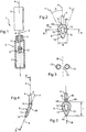
- the device 1 for packaging and application represented at figure 1 comprises a container 2 containing a product P to be applied and an applicator 3 comprising a rod 4 of longitudinal axis X, provided at one end with a gripping element 5 also constituting a sealing cap of the container 2 and at the other end of an application element 6.
- the axis X of the rod 4 is rectilinear but it could be curved, alternatively.
- the container 2 is provided in the upper part with a neck 7.
- the gripping element 5 is screwed on the neck 7 but could alternatively be fixed otherwise, snap-fastening for example.
- the application element 6 has, as can be seen on the figure 5 , a generally symmetrical shape with respect to a median plane of symmetry M and comprises a cavity 12 which is delimited laterally by two branches 13 and axially by distal portions 14 and proximal 15 joining the branches 13.
- the latter are elongated along longitudinal axes respective Y extend substantially parallel to a plane B, as can be seen on the figure 4 , which makes with the axis X of the rod 4 an angle ⁇ which is for example between about 20 ° and about 30 °.
- the angle ⁇ between each Y axis and the median plane of symmetry M is, for example, between 5 and 45 °, as can be seen on FIG. figure 2 .
- the branches 13 and the distal 14 and proximal portions 15 are made by plastic injection and covered with a flocking.
- the distal portion 14 defines a single tip centered on a median axis.
- the application element 6 protrudes laterally from the rod 4, when the latter is observed along its axis.
- the shape of the distal 14 and proximal portions 15 is advantageously chosen so as to facilitate the crossing of the opening 11 of the container 2.
- the proximal portion 15 may thus comprise edges 60, adjacent to the stem 4, extending obliquely relative to the X axis, and the distal portion 14 may have a generally tapered shape.
- the branches 13 converge towards each other towards the distal portion 14 and the cavity 12 has, when the application element 6 is observed in elevation, a substantially triangular shape.
- the cavity 12 extends for example, as can be seen on the Figures 2 and 5 in particular, over more than a quarter of the width b of the applicator element 6 as well as over more than a quarter of its length l .
- the dimensions of the cavity 12 may be chosen as a function of the quantity of product that it is desired to possibly retain, particularly by capillarity, in the cavity 12 after removal of the applicator from the container.
- a wiper member 8 is engaged in the neck 7.
- This wiper member 8 comprises a flange 9 resting on the upper edge of the neck 7 and a wiper lip 10 defining in the example considered an orifice of spinning 11 of circular section, of diameter a, for example substantially equal to that of the rod 4.
- the latter has a diameter generally greater than 2.5 mm, for example of the order of 4 mm.
- the wiper member 8 may be sufficiently flexible so that the application element 6 can be extracted without significant deformation of the cavity 12.
- the product P present in the cavity 12 increases the autonomy of the applicator and can also improve comfort on application, facilitating the sliding of the applicator on the treated surface.
- the product P is for example intended to be applied to the lips and the user can deposit it on them, for example by bringing the rear face 20 of the applicator element 6 to their contact, as illustrated in FIG. figure 7 .
- the rear face 20 corresponds to that which is situated on the rear side when the application element 6 is observed with the branches 13 extending towards the front.
- the deposited product thickness may be different, which may allow the user to vary, for example, the brightness of the makeup.
- the product P present in the cavity 12 can be deposited and the product-laden surface P coming into contact with the lips can be relatively large, so that the lips can be made up pretty quickly.
- the application can be made only with the end of the distal portion 15, to draw an outline for example.
- the wiper member 8 is constituted by a block of a cellular material, elastically compressible.
- the wiper member 8 may be traversed at its center by a recess 42 defining the opening 11 of the container, as can be seen on the figure 9 , with one or more slits.
- the diameter of the recess 42 may for example correspond substantially to that of the rod 4.
- the wiper member may still, regardless of its nature, alveolar or not, have one or more slots, which may be contiguous edges or not.
- FIG. 10 We have represented figure 10 an elastomer wiper member 8 having a central opening, for example circular, for the passage of the rod and the applicator element and several slots 100, which may be radial.
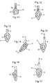
- Fixing the application element 6 on the rod 4 can be effected by various means.
- the proximal portion 15 is extended, as can be seen on the figure 5 , by a tip 18 engaged inside the rod 4.
- This tip 18 is for example glued, stapled or welded in the rod 4. The latter can be further crimped onto the tip, as shown in FIG. figure 11 .
- the figure 12 illustrates the possibility of securing the application element and the rod by snapping.
- the tip 18 is for example configured to snap onto a head 70 made at the end of the rod 4.
- the outer diameter of the tip 18 may then, for example, correspond substantially to that of the rod 4.
- the body of the applicator element can still be made in one piece with the rod 4, as illustrated in FIG. figure 13 .
- the applicator element 6 may have an edge 72 extending substantially in alignment with the rod 4.
- the applicator element 6 protrudes laterally from the rod 4 on the side opposite the edge 72.
- the application element 6 may also comprise more than one cavity 12, for example two cavities 12 as shown in FIG. figure 17 .
- the two cavities 12 are for example aligned along the longitudinal axis of the applicator element 6.
- the latter may have, for example, in front view, the general shape of an eight.
- the application element 6 extends obliquely relative to the longitudinal axis X of the rod 4.
- the applicator element 6 can be further extended, in a non-illustrated variant, along a curvilinear longitudinal axis.
- each branch 13 may for example extend with its longitudinal axis Y contained in a plane which is parallel to the longitudinal axis X of the rod 4.
- the cavity 12 opens at the front and at the back of the applicator element 6, when it is observed from the front, as on the figure 2 .
- the branches 13 may have, over at least a portion of their length, a solid cross section, of circular shape for example. We have illustrated on Figures 18 to 22 the possibility for the branches 13 to present a different shape in section. In a variant not shown, the branches 13 are hollow.
- the branches 13 may for example have a height h which is greater than the width w of the cavity 12 between the branches, as illustrated in FIG. figure 22 .
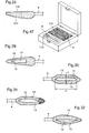
- the cavity 12 is filled with air before any contact of the application element 6 with the product contained in the container. It could be otherwise.
- the cavity 12 may for example be at least partially occupied by the flocking extending on the body of the applicator element 6, as is the case in the example illustrated in FIG. figure 23 .
- the flocking hairs covering the body of the application element 6 may for example be long enough for the bristles located on the facing faces of the branches 13 to meet.
- the application element 6 can, as illustrated in FIG. figure 24 , have two cavities 12 which are separated by a membrane 80 joining the branches 13 and located for example mid-thickness thereof.
- the cavity 12 can only lead to one face of the application element 6, as illustrated in FIG. figure 25 , the application element may comprise a membrane 82 defining for example at least partially the application surface by its outer face 83.
- This membrane 82 may for example be flocked externally.
- at least one orifice allows the product contained in the cavity 12 to gain the outer face 83, through the membrane 82.
- This membrane 80 may be flocked or not.
- the membrane 80 may be replaced by a grid 81, as shown in FIG. figure 26 .
- the membranes 80 or 82 may be molded in one piece with the branches 13.
- the membrane 82 may be replaced by an attached membrane 34, as illustrated in FIG. figure 27 .
- the membrane 34 may for example comprise a woven or a nonwoven, a foam, a perforated film, a grid, a felt, among others, and may be fixed by welding or gluing, for example.
- the membrane 34 may be permeable or not to the product P contained in the cavity 12.
- the body of the application element 6 is for example made at least partially by injection molding in a thermoplastic material, for example PVC, PU, EVA, SIS-SEB, nitrile, silicone, EPDM, Hytrel®, Pebax® , Santoprene®, or other thermoplastics, for example elastomers.
- a thermoplastic material for example PVC, PU, EVA, SIS-SEB, nitrile, silicone, EPDM, Hytrel®, Pebax® , Santoprene®, or other thermoplastics, for example elastomers.
- the applicator element 6 can also be made of non-thermoplastic materials, for example resins, in particular flexible resins, or be produced otherwise than by molding, for example by cutting.
- Figures 28 and 29 an applicator element 6 having upper and lower faces 131 which converge towards the distal end of the applicator element, at least along a portion of the cavity 12.
- the longitudinal axis X of the rod 4 is for example substantially parallel to one of these faces, for example the upper face 130.
- the application element 6 also has, when viewed from above as shown in FIG. figure 29 , substantially rectilinear longitudinal edges that converge towards the distal end.
- the application elements represented on the Figures 30 to 45 can advantageously be used for the application of a product, makeup or care, on keratin fibers, for example eyelashes or eyebrows.
- the single cavity 12 has an elongated shape, the ratio of the length m of the cavity to the greatest width n thereof being, for example, greater than or equal to 3, or 4, or 5 or 6. For example, there is 3 ⁇ m / n ⁇ 6.
- the figure 30 represents an application element whose cavity 12 has a substantially constant width over at least half of its length.
- the longitudinal edges of the branches 13 are rectilinear and parallel to each other, on either side of a median portion located mid-length of the cavity.
- the applicator element 6 is flocked and its distal portion is covered by bristles longer than those covering the branches 13. This distal portion serves for example to make up the corner of the eye.
- the branches 13 have unequal widths and the cavity 12 is off-center.
- the longitudinal edges of the branches 13 appear grooved, when the applicator element is observed from above.
- the figure 34 illustrates the possibility for the branches 13 of the application element to have concave longitudinal edges outwardly.
- the cavity may then have a width passing through a minimum between its two axial ends.
- the longitudinal edges of the branches are convex outwards, and the cavity 12 presents when viewed from above a lenticular shape.
- the application element represented in figure 36 has a curvilinear longitudinal axis Y and the free end of the applicator element is not on the longitudinal axis X of the rod.
- One of the branches has an outwardly convex outer edge and the other branches an outwardly concave outer edge.
- the application element of the figure 37 has a branch having an outer edge convex outward and another branch having a straight outer edge.
- the cavity 12 can be relatively narrow and form a capillary slot.
- the cavity 12 is wider than in the example of the figure 37 and has a variable width, passing through an extremum.
- the figure 39 illustrates the possibility for the applicator element to comprise two branches, one of which has a rectilinear outer edge and the other a concave outer edge outwards.
- the applicator element has a curvilinear longitudinal axis, as in the example of the figure 36 and the free end of the applicator element is located on the same side, relative to the longitudinal axis X of the rod, as practically all the rest of the applicator element.
- the figure 41 illustrates the possibility for one of the branches of the application element to have grooves while the other branch is devoid of it. These grooves extend for example transversely to the branch.
- the Figures 42 and 43 represent application members having a third limb 16 which joins the distal and proximal portions of the applicator element.
- the third branch is situated on one side of the plane defined by the longitudinal axes of the two branches 13, as can be seen on the figure 44 .
- the branch 16 has for example an arcuate shape.
- the two branches 13 and the third limb 16 are arranged in a regular manner around the longitudinal axis Y of the applicator element, the proximal portion of the applicator element having a section cross-section generally in the shape of a triangle or three-pointed star, as can be seen on figure 45 .
- the application elements of the Figures 30 to 45 are for example made at least partially by molding material, including a thermoplastic material.
- the application elements of the Figures 30 to 45 may allow to load the eyelashes with a relatively large amount of product. Two branches of the application element can be used simultaneously or successively to apply the product on the eyelashes.
- the application of the product may optionally be carried out in various ways depending on the desired result, the application element being for example used flat, on the edge or with various inclinations , the chosen orientation allowing the user to control, for example, the intensity of the makeup and possibly the combing of the eyelashes.
- the application element may have shapes other than those illustrated, for example diamond, circle or ellipse when the application element is observed from the front.
- the application elements may comprise magnetic particles, in order to be able for example to attract magnetic fibers contained in the product.
- an application element having a clearly elongated shape is advantageously made so as to allow this deformation.
- the rod of the applicator may optionally be devoid of the gripping element 5.
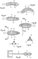
- the product P is for example contained, in the form of a paste, a compacted powder or a loose powder or otherwise, in a cup of a housing 110, as illustrated in FIG. figure 47 in an example which does not form part of the invention.
- the applicator is for example received in a corresponding housing 112 of the housing.
- the application element can be loaded into product by being brought into contact with it. Deformation of the application element may or may not occur at the moment the product is taken.
- the application element of Figures 48 to 51 has a more tapered shape when viewed from the side, as on the figure 50 .
- the angles i 1 , i 2 , i 3 are for example respectively between 6 and 16 °, i 1 being for example close to 11 °, 17.7 and 27.7, i 2 being for example close to 20.7 ° and 25.4 and 35.4, i 3 being for example close to 30.4 °.
- the front faces 200 and rear 20 converge towards the distal end 201 of the application element, being for example substantially planar.
- the sides of the applicator element may be rounded both in section in a plane perpendicular to the Y axis and when viewed from above or below on the Figures 48 and 49 .
- the height of the cavity 12, measured perpendicularly to the Y axis, may vary over at least half the length of the cavity.
- the length of the cavity 12, measured along the Y axis, may be less than or equal to 20 mm or greater than 20 mm.
- the cavity 12 may have a width that varies over more than half the length of the cavity 12.
- the container 2 is made with minus two parts 2a and 2b which are movable relative to each other so as to exert a constraint on the wiper member 8 and for example vary the section for the passage of the applicator element.
- the container has an extension 210 under the neck which presses on the wiper member so as to expand more or less thereof.
- the opening thereof may be sufficiently small to exert a stress on the applicator element, which may be deformed as it passes through the wiper member.
- the diameter of the opening of the wiper member is sufficiently large so that the applicator element undergoes no stress during the crossing of the wiper member. spin, or even undergoes a stress that does not cause a significant deformation of the cavity 12.
- the invention is not limited to a way of producing the means for varying the opening of the wiper member.
- the wiper member 8 may include a wavy wringing lip having corrugations 220 which allows it to deploy to the passage of the applicator element. This may make it possible not to exert on the applicator element a stress causing a substantial deformation of the cavity 12.
- the corrugations may for example be in the form of an alternation of hollows and bumps in the circumferential direction around the opening of the wiper member.
Landscapes
- Coating Apparatus (AREA)
- Cosmetics (AREA)
- Containers And Packaging Bodies Having A Special Means To Remove Contents (AREA)
- Brushes (AREA)
- Closures For Containers (AREA)
Applications Claiming Priority (1)
| Application Number | Priority Date | Filing Date | Title |
|---|---|---|---|
| FR0551353A FR2886112B1 (fr) | 2005-05-24 | 2005-05-24 | Dispositif de conditionnement et d'application |
Publications (3)
| Publication Number | Publication Date |
|---|---|
| EP1726235A2 EP1726235A2 (fr) | 2006-11-29 |
| EP1726235A3 EP1726235A3 (fr) | 2010-12-29 |
| EP1726235B1 true EP1726235B1 (fr) | 2018-08-29 |
Family
ID=35734909
Family Applications (1)
| Application Number | Title | Priority Date | Filing Date |
|---|---|---|---|
| EP06300519.3A Not-in-force EP1726235B1 (fr) | 2005-05-24 | 2006-05-24 | Dispositif de conditionnement et d'application |
Country Status (7)
| Country | Link |
|---|---|
| EP (1) | EP1726235B1 (enExample) |
| JP (4) | JP5259931B2 (enExample) |
| CN (2) | CN1868368A (enExample) |
| BR (2) | BRPI0602613A (enExample) |
| ES (1) | ES2692200T3 (enExample) |
| FR (1) | FR2886112B1 (enExample) |
| RU (1) | RU2327400C2 (enExample) |
Families Citing this family (66)
| Publication number | Priority date | Publication date | Assignee | Title |
|---|---|---|---|---|
| FR2910255B1 (fr) | 2006-12-21 | 2009-08-21 | Oreal | Applicateur pour appliquer un produit cosmetique sur les matieres keratiniques |
| FR2925265B1 (fr) * | 2007-12-20 | 2011-01-07 | Oreal | Dispositif de conditionnement et de distribution d'un stick de produit, notamment d'un produit cosmetique. |
| US20090276973A1 (en) * | 2008-05-06 | 2009-11-12 | Herve Bouix | Cosmetic Applicator Assembly |
| JP5324900B2 (ja) * | 2008-12-08 | 2013-10-23 | 花王株式会社 | 口唇化粧料塗布具 |
| FR2946846B1 (fr) * | 2009-06-17 | 2011-07-08 | Oreal | Dispostif de conditionnement et d'application comportant un rouleau d'application |
| FR2947432B1 (fr) * | 2009-07-02 | 2014-11-21 | Lvmh Rech | Dispositif pour l'application d'un produit cosmetique comportant des particules magnetiques et ensemble comprenant le dispositif. |
| JP4713686B1 (ja) * | 2009-10-09 | 2011-06-29 | 花王株式会社 | 口唇化粧料塗布装置 |
| KR200459830Y1 (ko) * | 2009-10-30 | 2012-04-19 | (주)아모레퍼시픽 | 자력을 이용하여 도포구를 본체의 입구로 안내하는 립글로스 용기 |
| FR2951920B1 (fr) * | 2009-11-04 | 2015-09-18 | Oreal | Dispositif de conditionnement et d'application d'un produit cosmetique sur les levres. |
| JP4840831B2 (ja) | 2010-04-27 | 2011-12-21 | 株式会社 資生堂 | 化粧用塗布体 |
| JP5704482B2 (ja) * | 2010-09-06 | 2015-04-22 | フィグラ株式会社 | 液体化粧料塗布体 |
| JP5720978B2 (ja) * | 2010-09-10 | 2015-05-20 | フィグラ株式会社 | 液体化粧料塗布具 |
| FR2971923B1 (fr) | 2011-02-28 | 2013-11-08 | Oreal | Dispositif de conditionnement et d'application d'un produit |
| FR2976165B1 (fr) * | 2011-06-07 | 2014-10-24 | Oreal | Ensemble comportant une composition contenant des fibres pour le maquillage des cils. |
| DE202011050425U1 (de) * | 2011-06-10 | 2011-08-09 | Klaus Sindel | Applikator zur Aufbringung von kosmetischem Material |
| FR2981835B1 (fr) | 2011-11-02 | 2014-04-11 | Oreal | Organe d'application d'un produit cosmetique et ensemble de conditionnement et d'application comportant un tel organe |
| JP5913366B2 (ja) | 2011-12-01 | 2016-04-27 | 株式会社新和製作所 | 化粧用塗布具 |
| JP6053290B2 (ja) * | 2012-02-06 | 2016-12-27 | 株式会社アーツブレインズ | 二重瞼形成溶液用アプリケータ及び容器 |
| FR2989256B1 (fr) | 2012-04-11 | 2014-11-28 | Oreal | Dispositif de conditionnement et d'application d'un produit cosmetique ou de soin sur les levres |
| FR2994068B1 (fr) * | 2012-08-01 | 2015-12-11 | Oreal | Applicateur de produit cosmetique, dispositif et procede associe |
| JP5718983B2 (ja) * | 2013-06-21 | 2015-05-13 | 花王株式会社 | 口唇化粧料塗布具 |
| WO2015029225A1 (ja) * | 2013-08-30 | 2015-03-05 | 株式会社 新和製作所 | 化粧用塗布具 |
| FR3014654B1 (fr) * | 2013-12-13 | 2017-04-21 | Oreal | Applicateur pour appliquer un produit cosmetique ou de soin sur les cils ou les sourcils |
| JP5801943B1 (ja) * | 2014-06-04 | 2015-10-28 | 花王株式会社 | 化粧料塗布具 |
| CN105899100B (zh) * | 2013-12-26 | 2019-09-17 | 花王株式会社 | 化妆品涂布用具 |
| JP5801942B2 (ja) * | 2013-12-26 | 2015-10-28 | 花王株式会社 | 化粧料塗布具 |
| WO2015098686A1 (ja) * | 2013-12-26 | 2015-07-02 | 花王株式会社 | 化粧料塗布具 |
| JP6292966B2 (ja) * | 2014-04-30 | 2018-03-14 | 花王株式会社 | 口唇化粧料塗布装置 |
| JP6394131B2 (ja) * | 2014-07-09 | 2018-09-26 | 花王株式会社 | 化粧料塗布具 |
| JP6394179B2 (ja) * | 2014-08-25 | 2018-09-26 | 花王株式会社 | 塗布具 |
| FR3026281B1 (fr) | 2014-09-25 | 2018-08-24 | L'oreal | Organe d'application comportant deux parties assemblees. |
| US9549602B2 (en) | 2014-10-09 | 2017-01-24 | Elc Management Llc | Foundation makeup and concealer composition |
| FR3029089B1 (fr) * | 2014-12-02 | 2018-03-02 | L'oreal | Dispositif de conditionnement et d'application d'eyeliner |
| FR3036594B1 (fr) * | 2015-05-28 | 2018-08-17 | L'oreal | Applicateur cosmetique |
| JP6045640B1 (ja) * | 2015-06-04 | 2016-12-14 | 株式会社 資生堂 | 化粧補助用具、化粧容器および化粧方法 |
| FR3037490B1 (fr) | 2015-06-19 | 2017-07-21 | Oreal | Applicateur cosmetique |
| JP2017006291A (ja) * | 2015-06-19 | 2017-01-12 | 株式会社アートネイチャー | まつ毛美容液用スパチュラ |
| KR101730876B1 (ko) | 2015-12-01 | 2017-04-28 | (주)연우 | 내용물 도포가 용이한 화장품 용기 |
| JP6157712B2 (ja) * | 2015-12-28 | 2017-07-05 | 株式会社 資生堂 | 目元化粧用塗布具および目元化粧用具 |
| CN107758110A (zh) * | 2016-08-16 | 2018-03-06 | 株式会社爱茉莉太平洋 | 包括具有临时存储部的植绒头的吸管式容器 |
| DE102016215288A1 (de) * | 2016-08-16 | 2018-02-22 | Thomas-Maximilian Böhm | Vorrichtung zum Auftragen eines flüssigen Mediums |
| DE202016105241U1 (de) * | 2016-09-20 | 2017-12-21 | Klaus Sindel | Applikator zur Aufbringung von kosmetischem Material |
| FR3058622B1 (fr) * | 2016-11-17 | 2019-08-23 | L'oreal | Applicateur pour appliquer un produit cosmetique sur les matieres keratiniques |
| KR102298971B1 (ko) * | 2017-05-23 | 2021-09-07 | 주식회사 에스쁘아 | 화장용 팁 및 이를 포함하는 화장 도구 |
| FR3068223B1 (fr) * | 2017-06-30 | 2021-06-25 | Albea Services | Embout applicateur pour produit cosmetique, applicateur et ensemble applicateur associes |
| KR102350799B1 (ko) * | 2017-07-19 | 2022-01-14 | (주)아모레퍼시픽 | 팁 어플리케이터 및 이를 포함하는 화장료 도포장치 |
| KR102201513B1 (ko) * | 2017-08-30 | 2021-01-13 | (주)아모레퍼시픽 | 팁 어플리케이터 및 이를 포함하는 화장료 도포장치 |
| FR3070839B1 (fr) * | 2017-09-12 | 2025-04-11 | Oreal | Applicateur cosmetique |
| FR3070841B1 (fr) | 2017-09-12 | 2021-07-16 | Oreal | Applicateur cosmetique |
| FR3070842B1 (fr) | 2017-09-12 | 2021-07-16 | Oreal | Applicateur cosmetique |
| KR20200035111A (ko) * | 2017-09-14 | 2020-04-01 | 에이엠지 컴퍼니 리미티드 | 화장품 용기용 패킹 및 화장품 용기 |
| CN111246772B (zh) * | 2017-10-20 | 2023-11-07 | 欧莱雅 | 用于制造用于涂抹美容组合物的个性化涂抹器的方法 |
| KR102201522B1 (ko) * | 2017-12-18 | 2021-01-12 | (주)아모레퍼시픽 | 팁 어플리케이터 및 이를 포함하는 화장료 도포장치 |
| WO2019157205A1 (en) * | 2018-02-08 | 2019-08-15 | TLH Beauty LLC | Cosmetic applicator holder; assembly comprising a holder, an applicator and a vessel and a method for applying make-up |
| CN112566526B (zh) * | 2018-08-10 | 2025-05-30 | 株式会社爱茉莉太平洋 | 端头涂敷器以及包含其的化妆品涂敷装置 |
| CN112566527A (zh) * | 2018-08-10 | 2021-03-26 | 株式会社爱茉莉太平洋 | 端头涂敷器以及包含其的化妆料涂敷装置 |
| US12310484B2 (en) | 2019-05-22 | 2025-05-27 | Toly Management Ltd. | Cosmetic applicator with separately formed surfaces |
| FR3097728B1 (fr) * | 2019-06-28 | 2025-03-28 | Oreal | Dispositif de prélèvement et d’application d’une composition cosmétique |
| FR3103689B1 (fr) * | 2019-11-28 | 2024-07-12 | Oreal | Applicateur pour le maquillage des fibres kératiniques humaines, notamment des sourcils |
| FR3111773B1 (fr) * | 2020-06-26 | 2022-07-29 | Oreal | Applicateur cosmétique à cavité supportée par des branches support |
| JP2022134868A (ja) * | 2021-03-04 | 2022-09-15 | ロレアル | 発泡体を導入したアプリケータ |
| CN116725312A (zh) * | 2022-03-01 | 2023-09-12 | 洽兴包装工业(中国)有限公司 | 多瓣化妆品涂敷器 |
| CN116725308A (zh) * | 2022-03-01 | 2023-09-12 | 洽兴包装工业(中国)有限公司 | 化妆品涂敷器 |
| JP2023166778A (ja) * | 2022-05-10 | 2023-11-22 | ロレアル | アプリケータヘッド、アプリケータデバイス、および化粧方法 |
| CN117941919A (zh) * | 2022-10-31 | 2024-04-30 | 洽兴包装工业(中国)有限公司 | 涂抹器及包含该涂抹器的容器和制造该涂抹器的模具 |
| CN116268750A (zh) * | 2022-12-08 | 2023-06-23 | 洽兴包装工业(中国)有限公司 | 化妆容器用内塞 |
Family Cites Families (17)
| Publication number | Priority date | Publication date | Assignee | Title |
|---|---|---|---|---|
| FR2633256B1 (fr) * | 1988-06-23 | 1990-09-21 | Oreal | Ensemble comportant un reservoir contenant un liquide et un applicateur equipe d'un embout distributeur souple |
| JPH0613714U (ja) * | 1992-08-03 | 1994-02-22 | フィグラ株式会社 | 化粧料容器 |
| FR2722381B1 (fr) * | 1994-07-12 | 1997-02-28 | Oreal | Applicateur pour l'application d'un produit liquide et ensemble de maquillage muni d'un tel applicateur |
| DE4446521A1 (de) * | 1994-12-24 | 1996-06-27 | Estee Lauder Inc | Mascara-Bürstchen |
| FR2745272B1 (fr) | 1996-02-28 | 1998-04-24 | Oreal | Dispositif de conditionnement et d'application et element de recharge pour un tel dispositif |
| FR2745479B1 (fr) | 1996-03-01 | 1998-04-30 | Oreal | Applicateur de produit et ensemble de conditionnement comprenant un tel applicateur |
| FR2762494B1 (fr) * | 1997-04-28 | 1999-06-25 | Oreal | Applicateur et ensemble de conditionnement et d'application utilisant un tel applicateur |
| FR2771077B1 (fr) * | 1997-11-14 | 2000-01-14 | Oreal | Dispositif de conditionnement et d'application comportant un recipient, un applicateur ergonomique et un organe d'essorage |
| FR2793663B1 (fr) * | 1999-05-19 | 2001-08-03 | Oreal | Dispositif de conditionnement et d'application d'un produit cosmetique, notamment pour le maquillage des levres |
| US6120202A (en) | 1999-06-21 | 2000-09-19 | Donsky; Robin | Nail polish applicator bottle |
| JP2001161434A (ja) * | 1999-12-07 | 2001-06-19 | Kose Corp | 粘性液状化粧料用容器 |
| FR2805720B1 (fr) * | 2000-03-03 | 2002-08-16 | Oreal | Dispositif comprenant un applicateur et/ou un organe d'essorage magnetique |
| FR2810860B1 (fr) * | 2000-06-28 | 2003-02-21 | Oreal | Dispositif pour l'application d'un produit sur les cils ou les sourcils |
| US6676320B1 (en) * | 2001-11-26 | 2004-01-13 | Key Beauté INC | Device for dispensing mascara |
| FR2836031B1 (fr) * | 2002-02-19 | 2004-11-26 | Oreal | Applicateur comportant un element d'application configure pour appliquer un produit sur la peau |
| US7261483B2 (en) * | 2002-04-30 | 2007-08-28 | L'ORéAL S.A. | Device, system, and method for applying a product |
| FR2855379B1 (fr) * | 2003-05-27 | 2005-07-29 | Oreal | Dispositif de conditionnement et d'application |
-
2005
- 2005-05-24 FR FR0551353A patent/FR2886112B1/fr not_active Expired - Fee Related
-
2006
- 2006-05-24 EP EP06300519.3A patent/EP1726235B1/fr not_active Not-in-force
- 2006-05-24 CN CNA2006100809011A patent/CN1868368A/zh active Pending
- 2006-05-24 BR BRPI0602613 patent/BRPI0602613A/pt not_active IP Right Cessation
- 2006-05-24 CN CNA2006100809026A patent/CN1868369A/zh active Pending
- 2006-05-24 ES ES06300519.3T patent/ES2692200T3/es active Active
- 2006-05-24 JP JP2006170644A patent/JP5259931B2/ja not_active Expired - Fee Related
- 2006-05-24 RU RU2006117851/12A patent/RU2327400C2/ru active
- 2006-05-24 JP JP2006170645A patent/JP5259932B2/ja not_active Expired - Fee Related
- 2006-05-24 BR BRPI0602612-5A patent/BRPI0602612B1/pt not_active IP Right Cessation
-
2012
- 2012-12-20 JP JP2012278349A patent/JP5922012B2/ja not_active Expired - Fee Related
- 2012-12-20 JP JP2012278348A patent/JP5922011B2/ja not_active Expired - Fee Related
Also Published As
| Publication number | Publication date |
|---|---|
| JP2006326320A (ja) | 2006-12-07 |
| FR2886112B1 (fr) | 2007-08-10 |
| EP1726235A3 (fr) | 2010-12-29 |
| JP2013056213A (ja) | 2013-03-28 |
| BRPI0602613A (pt) | 2007-02-21 |
| JP5259932B2 (ja) | 2013-08-07 |
| CN1868369A (zh) | 2006-11-29 |
| RU2327400C2 (ru) | 2008-06-27 |
| BRPI0602612A (pt) | 2007-02-21 |
| JP5922011B2 (ja) | 2016-05-24 |
| CN1868368A (zh) | 2006-11-29 |
| EP1726235A2 (fr) | 2006-11-29 |
| ES2692200T3 (es) | 2018-11-30 |
| RU2006117851A (ru) | 2007-12-10 |
| JP2013052302A (ja) | 2013-03-21 |
| FR2886112A1 (fr) | 2006-12-01 |
| JP5922012B2 (ja) | 2016-05-24 |
| JP2006346469A (ja) | 2006-12-28 |
| BRPI0602612B1 (pt) | 2019-04-30 |
| JP5259931B2 (ja) | 2013-08-07 |
Similar Documents
| Publication | Publication Date | Title |
|---|---|---|
| EP1726235B1 (fr) | Dispositif de conditionnement et d'application | |
| EP1623650B1 (fr) | Dispositif de conditionnement et d'application d'un produit cosmétique ou de soin | |
| EP1726234B1 (fr) | Applicateur pour appliquer un produit sur les cils et/ou les sourcils | |
| EP1477083B2 (fr) | Applicateur et dispositif de conditionnement et d'application comportant un tel applicateur | |
| EP0978241B1 (fr) | Dispositif pour l'application d'un produit de maquillage comportant une brosse, procédé de fabrication et applicateur | |
| EP0861616B1 (fr) | Dispositif d'application d'un produit de maquillage de fibres kératiniques, notamment des cils, et ensemble de conditionnement et d'application utilisant un tel dispositif | |
| EP1481607B2 (fr) | Dispositif de conditionnement et d'application d'un produit, comportant un organe d'essorage | |
| FR3026281A1 (fr) | Organe d'application comportant deux parties assemblees. | |
| EP1481608B1 (fr) | Dispositif de conditionnement et d'application | |
| FR3094877A1 (fr) | Applicateur cosmétique avec portion de retenue de fluide flexible | |
| EP1504691A1 (fr) | Applicateur et dispositif de conditionnement et d'application comportant un tel applicateur. | |
| FR2908018A1 (fr) | Applicateur pour appliquer un produit sur les cils ou les sourcils | |
| FR2932657A1 (fr) | Brosse a mascara. | |
| FR3004905A1 (fr) | Applicateur pour appliquer un produit sur les cils et/ou les sourcils | |
| FR2916328A1 (fr) | Brosse pour l'application d'un produit sur les cils et/ou les sourcils | |
| WO2016051072A1 (fr) | Applicateur flexible | |
| FR2979807A1 (fr) | Applicateur pour appliquer un produit sur les cils ou les sourcils | |
| FR3058620B1 (fr) | Applicateur flexible pointu | |
| EP1440629B1 (fr) | Applicateur pour d'appliquer un produit sur une partie du corps humain | |
| EP1745717A2 (fr) | Applicateur et dispositif de conditionnement et d'application comportant un tel applicateur | |
| EP1369055A2 (fr) | Applicateur comportant une tige reliée par une articulation à un organe de préhension | |
| FR3111773A1 (fr) | Applicateur cosmétique à cavité supportée par des branches support | |
| EP1797789B1 (fr) | Applicateur à réserve de produit, notamment pour vernis à ongles | |
| FR3066682A1 (fr) | Applicateur en forme de cuillere | |
| FR3058621A1 (fr) | Element d’application comprenant des cavites concaves paralleles |
Legal Events
| Date | Code | Title | Description |
|---|---|---|---|
| PUAI | Public reference made under article 153(3) epc to a published international application that has entered the european phase |
Free format text: ORIGINAL CODE: 0009012 |
|
| 17P | Request for examination filed |
Effective date: 20060603 |
|
| AK | Designated contracting states |
Kind code of ref document: A2 Designated state(s): AT BE BG CH CY CZ DE DK EE ES FI FR GB GR HU IE IS IT LI LT LU LV MC NL PL PT RO SE SI SK TR |
|
| AX | Request for extension of the european patent |
Extension state: AL BA HR MK YU |
|
| PUAL | Search report despatched |
Free format text: ORIGINAL CODE: 0009013 |
|
| AK | Designated contracting states |
Kind code of ref document: A3 Designated state(s): AT BE BG CH CY CZ DE DK EE ES FI FR GB GR HU IE IS IT LI LT LU LV MC NL PL PT RO SE SI SK TR |
|
| AX | Request for extension of the european patent |
Extension state: AL BA HR MK YU |
|
| 17Q | First examination report despatched |
Effective date: 20110111 |
|
| AKX | Designation fees paid |
Designated state(s): AT BE BG CH CY CZ DE DK EE ES FI FR GB GR HU IE IS IT LI LT LU LV MC NL PL PT RO SE SI SK TR |
|
| GRAP | Despatch of communication of intention to grant a patent |
Free format text: ORIGINAL CODE: EPIDOSNIGR1 |
|
| STAA | Information on the status of an ep patent application or granted ep patent |
Free format text: STATUS: GRANT OF PATENT IS INTENDED |
|
| INTG | Intention to grant announced |
Effective date: 20180405 |
|
| RIN1 | Information on inventor provided before grant (corrected) |
Inventor name: GUERET, JEAN-LOUIS |
|
| GRAS | Grant fee paid |
Free format text: ORIGINAL CODE: EPIDOSNIGR3 |
|
| GRAA | (expected) grant |
Free format text: ORIGINAL CODE: 0009210 |
|
| STAA | Information on the status of an ep patent application or granted ep patent |
Free format text: STATUS: THE PATENT HAS BEEN GRANTED |
|
| AK | Designated contracting states |
Kind code of ref document: B1 Designated state(s): AT BE BG CH CY CZ DE DK EE ES FI FR GB GR HU IE IS IT LI LT LU LV MC NL PL PT RO SE SI SK TR |
|
| REG | Reference to a national code |
Ref country code: GB Ref legal event code: FG4D Free format text: NOT ENGLISH |
|
| REG | Reference to a national code |
Ref country code: CH Ref legal event code: EP |
|
| REG | Reference to a national code |
Ref country code: AT Ref legal event code: REF Ref document number: 1034116 Country of ref document: AT Kind code of ref document: T Effective date: 20180915 |
|
| REG | Reference to a national code |
Ref country code: IE Ref legal event code: FG4D Free format text: LANGUAGE OF EP DOCUMENT: FRENCH |
|
| REG | Reference to a national code |
Ref country code: DE Ref legal event code: R096 Ref document number: 602006056195 Country of ref document: DE |
|
| REG | Reference to a national code |
Ref country code: ES Ref legal event code: FG2A Ref document number: 2692200 Country of ref document: ES Kind code of ref document: T3 Effective date: 20181130 |
|
| REG | Reference to a national code |
Ref country code: NL Ref legal event code: MP Effective date: 20180829 |
|
| REG | Reference to a national code |
Ref country code: LT Ref legal event code: MG4D |
|
| PG25 | Lapsed in a contracting state [announced via postgrant information from national office to epo] |
Ref country code: FI Free format text: LAPSE BECAUSE OF FAILURE TO SUBMIT A TRANSLATION OF THE DESCRIPTION OR TO PAY THE FEE WITHIN THE PRESCRIBED TIME-LIMIT Effective date: 20180829 Ref country code: NL Free format text: LAPSE BECAUSE OF FAILURE TO SUBMIT A TRANSLATION OF THE DESCRIPTION OR TO PAY THE FEE WITHIN THE PRESCRIBED TIME-LIMIT Effective date: 20180829 Ref country code: SE Free format text: LAPSE BECAUSE OF FAILURE TO SUBMIT A TRANSLATION OF THE DESCRIPTION OR TO PAY THE FEE WITHIN THE PRESCRIBED TIME-LIMIT Effective date: 20180829 Ref country code: IS Free format text: LAPSE BECAUSE OF FAILURE TO SUBMIT A TRANSLATION OF THE DESCRIPTION OR TO PAY THE FEE WITHIN THE PRESCRIBED TIME-LIMIT Effective date: 20181229 Ref country code: GR Free format text: LAPSE BECAUSE OF FAILURE TO SUBMIT A TRANSLATION OF THE DESCRIPTION OR TO PAY THE FEE WITHIN THE PRESCRIBED TIME-LIMIT Effective date: 20181130 Ref country code: LT Free format text: LAPSE BECAUSE OF FAILURE TO SUBMIT A TRANSLATION OF THE DESCRIPTION OR TO PAY THE FEE WITHIN THE PRESCRIBED TIME-LIMIT Effective date: 20180829 Ref country code: BG Free format text: LAPSE BECAUSE OF FAILURE TO SUBMIT A TRANSLATION OF THE DESCRIPTION OR TO PAY THE FEE WITHIN THE PRESCRIBED TIME-LIMIT Effective date: 20181129 |
|
| REG | Reference to a national code |
Ref country code: AT Ref legal event code: MK05 Ref document number: 1034116 Country of ref document: AT Kind code of ref document: T Effective date: 20180829 |
|
| PG25 | Lapsed in a contracting state [announced via postgrant information from national office to epo] |
Ref country code: LV Free format text: LAPSE BECAUSE OF FAILURE TO SUBMIT A TRANSLATION OF THE DESCRIPTION OR TO PAY THE FEE WITHIN THE PRESCRIBED TIME-LIMIT Effective date: 20180829 |
|
| PG25 | Lapsed in a contracting state [announced via postgrant information from national office to epo] |
Ref country code: AT Free format text: LAPSE BECAUSE OF FAILURE TO SUBMIT A TRANSLATION OF THE DESCRIPTION OR TO PAY THE FEE WITHIN THE PRESCRIBED TIME-LIMIT Effective date: 20180829 Ref country code: PL Free format text: LAPSE BECAUSE OF FAILURE TO SUBMIT A TRANSLATION OF THE DESCRIPTION OR TO PAY THE FEE WITHIN THE PRESCRIBED TIME-LIMIT Effective date: 20180829 Ref country code: CZ Free format text: LAPSE BECAUSE OF FAILURE TO SUBMIT A TRANSLATION OF THE DESCRIPTION OR TO PAY THE FEE WITHIN THE PRESCRIBED TIME-LIMIT Effective date: 20180829 Ref country code: RO Free format text: LAPSE BECAUSE OF FAILURE TO SUBMIT A TRANSLATION OF THE DESCRIPTION OR TO PAY THE FEE WITHIN THE PRESCRIBED TIME-LIMIT Effective date: 20180829 Ref country code: EE Free format text: LAPSE BECAUSE OF FAILURE TO SUBMIT A TRANSLATION OF THE DESCRIPTION OR TO PAY THE FEE WITHIN THE PRESCRIBED TIME-LIMIT Effective date: 20180829 |
|
| PG25 | Lapsed in a contracting state [announced via postgrant information from national office to epo] |
Ref country code: DK Free format text: LAPSE BECAUSE OF FAILURE TO SUBMIT A TRANSLATION OF THE DESCRIPTION OR TO PAY THE FEE WITHIN THE PRESCRIBED TIME-LIMIT Effective date: 20180829 Ref country code: SK Free format text: LAPSE BECAUSE OF FAILURE TO SUBMIT A TRANSLATION OF THE DESCRIPTION OR TO PAY THE FEE WITHIN THE PRESCRIBED TIME-LIMIT Effective date: 20180829 |
|
| REG | Reference to a national code |
Ref country code: DE Ref legal event code: R097 Ref document number: 602006056195 Country of ref document: DE |
|
| PLBE | No opposition filed within time limit |
Free format text: ORIGINAL CODE: 0009261 |
|
| STAA | Information on the status of an ep patent application or granted ep patent |
Free format text: STATUS: NO OPPOSITION FILED WITHIN TIME LIMIT |
|
| PGFP | Annual fee paid to national office [announced via postgrant information from national office to epo] |
Ref country code: BE Payment date: 20190527 Year of fee payment: 5 Ref country code: ES Payment date: 20190603 Year of fee payment: 14 |
|
| 26N | No opposition filed |
Effective date: 20190531 |
|
| PG25 | Lapsed in a contracting state [announced via postgrant information from national office to epo] |
Ref country code: SI Free format text: LAPSE BECAUSE OF FAILURE TO SUBMIT A TRANSLATION OF THE DESCRIPTION OR TO PAY THE FEE WITHIN THE PRESCRIBED TIME-LIMIT Effective date: 20180829 |
|
| PGFP | Annual fee paid to national office [announced via postgrant information from national office to epo] |
Ref country code: GB Payment date: 20190522 Year of fee payment: 14 |
|
| REG | Reference to a national code |
Ref country code: CH Ref legal event code: PL |
|
| PG25 | Lapsed in a contracting state [announced via postgrant information from national office to epo] |
Ref country code: MC Free format text: LAPSE BECAUSE OF FAILURE TO SUBMIT A TRANSLATION OF THE DESCRIPTION OR TO PAY THE FEE WITHIN THE PRESCRIBED TIME-LIMIT Effective date: 20180829 Ref country code: CH Free format text: LAPSE BECAUSE OF NON-PAYMENT OF DUE FEES Effective date: 20190531 Ref country code: LI Free format text: LAPSE BECAUSE OF NON-PAYMENT OF DUE FEES Effective date: 20190531 |
|
| REG | Reference to a national code |
Ref country code: BE Ref legal event code: MM Effective date: 20190531 |
|
| PG25 | Lapsed in a contracting state [announced via postgrant information from national office to epo] |
Ref country code: LU Free format text: LAPSE BECAUSE OF NON-PAYMENT OF DUE FEES Effective date: 20190524 |
|
| PG25 | Lapsed in a contracting state [announced via postgrant information from national office to epo] |
Ref country code: TR Free format text: LAPSE BECAUSE OF FAILURE TO SUBMIT A TRANSLATION OF THE DESCRIPTION OR TO PAY THE FEE WITHIN THE PRESCRIBED TIME-LIMIT Effective date: 20180829 |
|
| PG25 | Lapsed in a contracting state [announced via postgrant information from national office to epo] |
Ref country code: IE Free format text: LAPSE BECAUSE OF NON-PAYMENT OF DUE FEES Effective date: 20190524 |
|
| PG25 | Lapsed in a contracting state [announced via postgrant information from national office to epo] |
Ref country code: BE Free format text: LAPSE BECAUSE OF NON-PAYMENT OF DUE FEES Effective date: 20190531 |
|
| PG25 | Lapsed in a contracting state [announced via postgrant information from national office to epo] |
Ref country code: PT Free format text: LAPSE BECAUSE OF FAILURE TO SUBMIT A TRANSLATION OF THE DESCRIPTION OR TO PAY THE FEE WITHIN THE PRESCRIBED TIME-LIMIT Effective date: 20181229 |
|
| PGFP | Annual fee paid to national office [announced via postgrant information from national office to epo] |
Ref country code: FR Payment date: 20200414 Year of fee payment: 15 |
|
| PGFP | Annual fee paid to national office [announced via postgrant information from national office to epo] |
Ref country code: IT Payment date: 20200414 Year of fee payment: 15 |
|
| REG | Reference to a national code |
Ref country code: DE Ref legal event code: R119 Ref document number: 602006056195 Country of ref document: DE |
|
| GBPC | Gb: european patent ceased through non-payment of renewal fee |
Effective date: 20200524 |
|
| PG25 | Lapsed in a contracting state [announced via postgrant information from national office to epo] |
Ref country code: GB Free format text: LAPSE BECAUSE OF NON-PAYMENT OF DUE FEES Effective date: 20200524 |
|
| PG25 | Lapsed in a contracting state [announced via postgrant information from national office to epo] |
Ref country code: CY Free format text: LAPSE BECAUSE OF FAILURE TO SUBMIT A TRANSLATION OF THE DESCRIPTION OR TO PAY THE FEE WITHIN THE PRESCRIBED TIME-LIMIT Effective date: 20180829 Ref country code: DE Free format text: LAPSE BECAUSE OF NON-PAYMENT OF DUE FEES Effective date: 20201201 |
|
| PG25 | Lapsed in a contracting state [announced via postgrant information from national office to epo] |
Ref country code: HU Free format text: LAPSE BECAUSE OF FAILURE TO SUBMIT A TRANSLATION OF THE DESCRIPTION OR TO PAY THE FEE WITHIN THE PRESCRIBED TIME-LIMIT; INVALID AB INITIO Effective date: 20060524 |
|
| REG | Reference to a national code |
Ref country code: ES Ref legal event code: FD2A Effective date: 20211004 |
|
| PG25 | Lapsed in a contracting state [announced via postgrant information from national office to epo] |
Ref country code: ES Free format text: LAPSE BECAUSE OF NON-PAYMENT OF DUE FEES Effective date: 20200525 |
|
| PG25 | Lapsed in a contracting state [announced via postgrant information from national office to epo] |
Ref country code: FR Free format text: LAPSE BECAUSE OF NON-PAYMENT OF DUE FEES Effective date: 20210531 |
|
| PG25 | Lapsed in a contracting state [announced via postgrant information from national office to epo] |
Ref country code: IT Free format text: LAPSE BECAUSE OF NON-PAYMENT OF DUE FEES Effective date: 20200524 |
|
| PG25 | Lapsed in a contracting state [announced via postgrant information from national office to epo] |
Ref country code: IT Free format text: LAPSE BECAUSE OF NON-PAYMENT OF DUE FEES Effective date: 20210524 |