EP1724875A1 - Dispositif et procédé d'étalonnage d'un réseau d'antennes - Google Patents
Dispositif et procédé d'étalonnage d'un réseau d'antennes Download PDFInfo
- Publication number
- EP1724875A1 EP1724875A1 EP05255348A EP05255348A EP1724875A1 EP 1724875 A1 EP1724875 A1 EP 1724875A1 EP 05255348 A EP05255348 A EP 05255348A EP 05255348 A EP05255348 A EP 05255348A EP 1724875 A1 EP1724875 A1 EP 1724875A1
- Authority
- EP
- European Patent Office
- Prior art keywords
- calibration
- antenna elements
- signals
- antenna
- signal
- Prior art date
- Legal status (The legal status is an assumption and is not a legal conclusion. Google has not performed a legal analysis and makes no representation as to the accuracy of the status listed.)
- Granted
Links
Images


Classifications
-
- H—ELECTRICITY
- H01—ELECTRIC ELEMENTS
- H01Q—ANTENNAS, i.e. RADIO AERIALS
- H01Q3/00—Arrangements for changing or varying the orientation or the shape of the directional pattern of the waves radiated from an antenna or antenna system
- H01Q3/26—Arrangements for changing or varying the orientation or the shape of the directional pattern of the waves radiated from an antenna or antenna system varying the relative phase or relative amplitude of energisation between two or more active radiating elements; varying the distribution of energy across a radiating aperture
- H01Q3/267—Phased-array testing or checking devices
Definitions
- the present invention relates to an array antenna calibration apparatus and an array antenna calibration method.
- the invention relates particularly to a technique for calibrating phase differences at array antenna ends.
- Digital cellular radio communication systems employing the DS-CDMA (Direct Spread Code Division Multiple Access) technology have been developed as next-generation mobile communication systems.
- the CDMA scheme is an access scheme in which channels are assigned according to codes to make simultaneous communication available.
- signal interference between channels used in simultaneous communication causes a problem and thus limits the channels available for simultaneous communication, thereby causing a limited channel capacity.
- techniques for restraining interference are effective.
- An adaptive array antenna which forms a beam for a desired user while it forms a null point for another user who becomes a significant source of interference, is able to increase the channel capacity. That is, the adaptive array antenna is focused in the direction of the desired user, and presents a null point in the direction of the user who becomes a significant source of interference. This makes it possible to receive a radio wave from the desired user with high sensitivity, and not to receive a radio wave from the significant interference source, so that the amount of interference is reduced, thereby increasing the channel capacity.
- Adaptive array antennas generate beams utilizing phase differences at antenna ends. Thus, phase variation in each radio unit will make it impossible to correctly control beam patterns.
- phase difference correction method for example, calibration signals are multiplexed, and the phase difference of the multiplexed signals is detected and corrected.
- FIG. 9 is a block diagram showing an example of an array antenna calibration apparatus, and it is equivalent to FIG. 1 of the following patent document 1.
- the conventional apparatus of FIG. 9 includes: antenna elements 100-1 to 100-8 constituting a linear antenna; transmitters 103; a calibration signal generator 104; adders 105; circulators 106; a receiver 107; an RF switch 108; a calibration factor calculating unit 109; multipliers 110; a power combiner 111; a user signal multiplexing unit 112; beam formers 113, one for each user "1" to "n". User signals sent from the beam formers 113 are multiplexed by the user signal multiplexing unit 112.
- each multiplier 110 multiplies the multiplexed signals by a calibration factor obtained by the calibration factor calculating unit 109, and then each adder 105 adds a calibration signal generated by the calibration signal generator 104.
- the resultant signals are input to the transmitters 103 and sent out from the corresponding antenna elements 100-1 to 100-6.
- the antenna elements 100-7 and 100-8, one on each side of the array antenna, are dummy antennae to each of which a non-reflection resistor 102 is coupled.
- the signals sent from the antenna elements 100-1 to 100-6 are electromagnetically coupled to the adjacent antenna elements and transmitted. These coupled components are taken out by the circulators 106 and are then received by the receiver 107 via the RF switch 108.
- calibration signals C1 and C3 sent from the antenna elements 100-1 and 100-3, respectively, are received by the antenna element 100-2 due to electromagnetic coupling between the antenna elements, and signals C1+C3 are taken out by the corresponding circulator 106 and are then input to one of the ports of the RF switch 108.
- signals C2+C4, signals C3+C5, and signals C4+C6 are input, one to each of the other ports of the RF switch 108.
- signals C3 and C5, electromagnetically coupled to the antenna elements 100-1 and 100-6, are power-synthesized by the power combiner 111 and are then received by the receiver 107 via the RF switch 108.
- the calibration factor calculating unit 109 measures the phase and the amplitude of each calibration signal to calculate a calibration factor. For example, signal patterns orthogonal to one another with no correlation therebetween are used as calibration signals C1 to C6, and signals C1 and C3 are subjected to correlation processing by the corresponding signal patterns of the signals C1 and C3, to obtain the phases and the amplitudes of the signals C1 and C3, and a factor for making uniform the amplitudes and the phases of the signals C1 and C3 is obtained. Likewise, the ports of the RF switch 108 are sequentially changed over, and factors for making uniform the amplitudes and the phases of signals C2 and C4, signals C3 and C5, signals C4 and C6, and signals C2 and C5 are individually obtained.
- the present invention provides an array antenna calibration apparatus and an array antenna calibration method.
- antenna elements e.g., dummy antennae disposed on either side of antenna elements that are to be subjected to calibration, are used for transceiving calibration signals, thereby realizing accurate, antenna element interval-independent calibration. Accordingly, antenna element interval deviation is allowed, and array antenna yields are reduced, thereby contributing to reduction of the manufacturing cost.
- FIG. 1 is a block diagram showing a construction (for downlink) of a radio transmitter to which an array antenna calibration apparatus of a first embodiment of the present invention is applied.
- the radio transmitter of FIG. 1 includes: antenna elements E0, E1, E2, E3, DA, and DB (in FIG.
- antenna elements 1, a total of six antenna elements) constituting a linear array antenna; beam formers 10-1 to 10-n (n is an integer not smaller than 2) for multiple users; a signal multiplexing unit 11; phase shifters 12, adders 13, and radio transmitter units 14 provided, one for each of the antenna elements E0, E1, E2, and E3; a calibration control unit 15; a calibration signal generating unit 16; an RF switch 17; a radio receiver unit 18; a calibration signal detecting unit 19; and a weight generating unit 20.
- Antenna elements DA and DB are disposed, one on each side of the linear array antenna and are dummy antennae for shaping emission patterns from the antenna elements E0, E1, E2, and E3. Note that the number of antenna elements should by no means be limited to the above.
- the signal multiplexing unit 11 multiplexes the user signals obtained from the beam formers 10-i.
- Each phase shifter 12 adjusts the phase of the multiplexed user signals, which are multiplexed by the signal multiplexing unit 11, according to a weighting factor obtained from the weight generating unit 20.
- Each adder 13 adds a calibration signal generated by the calibration signal generating unit 16 to the signal (main signal) which has undergone phase adjustment by the phase shifters 12.
- the radio transmitter units 14 carry out necessary radio transmission processing, such as modulating the calibration-signal-added signal by a specific modulation method and upconverting the modulated signal to a radio signal, and then sends the thus obtained radio signal from the antenna elements E0, E1, E2, and E3.
- the calibration signal generating unit 16, the adders 13, and radio transmitter units 14 serve as a calibration signal supply means for supplying calibration signals to antenna elements E0, E1, E2, and E3 that are to be subjected to calibration.
- the calibration control unit 15 controls calibration of the antenna elements E0, E1, E2, and E3.
- the calibration signal generating unit 16 generates necessary calibration signals under control of the calibration control unit 15 and supplies the generated calibration signals to the adders 13.
- the same calibration signal can be generated in a time-division manner, or alternatively, calibration signals having different frequencies or codes can be generated for the separate antenna elements E0, E1, E2, and E3.
- the following three methods are applicable: the time-division multiplexing method, in which signal-emitting antenna elements are switched over time, the code-division multiplexing method, in which different antennae emit signals which are spread with different spreading codes, and the frequency-division multiplexing method, in which different antennae emit signals at different frequencies.
- the RF switch (switch unit) 17 selectively outputs RF signals electromagnetically coupled to the antennae DA and DB (hereinafter also called dummy antennae DA and DB), which are dummy antennae, under control by the calibration control unit 15, and makes the radio receiver unit 18 receive the selected RF signal.
- the radio receiver unit 18 carries out necessary radio reception processing including downconverting the RF signal, which is received via the radio receiver unit 18, to an intermediate frequency (IF) signal and to a baseband signal and specific demodulation processing.
- the calibration signal detecting unit 19 detects a calibration signal from a signal which is received by the dummy antenna DA or DB and is then output from the radio receiver unit 18, under control of the calibration control unit 15.
- the above RF switch 17, the radio receiver unit 18, and the calibration signal detecting unit 19 serve as a calibration signal detecting means for detecting calibration signals from signals received by the dummy antenna elements DA and DB, disposed one on each side of the adjacent antennas E0, E1, E2, and E3 to be subjected to calibration.
- the weight generating unit 20 detects the phase differences among the calibration signals detected by the calibration signal detecting unit 19 and obtains weighting factors (weight values) to be supplied to the phase shifters 12.
- the weight generating unit 20 detects the calibration signal phase differences while accumulating each calibration signal detected time-divisionally by the calibration signal detecting unit 19 in a memory or the like.
- the calibration signals are simultaneously sent from the antenna elements E0, E1, E2, and E3, at different frequencies or with different codes, the calibration signals, detected by the calibration signal detecting unit 19 according to their frequencies or codes, are differentiated based on their frequencies and codes, and their phase differences are detected.
- the calibration control unit 15 and the weight generating unit 20 serve as a calibration control means for controlling the phases of signals to be sent from the antenna elements E0, E1, E2, and E3 that are to be subjected to calibration, based on the above-described calibration signal phase differences.
- a block constituted of the calibration control unit 15, the calibration signal generating unit 16, the RF switch 17, the radio receiver unit 18, the calibration signal detecting unit 19, and the weight generating unit 20, serves as an array antenna calibration apparatus.
- Calibration signals generated by the calibration signal generating unit 16 are added (multiplexed) by the adders 13 to the main signals sent to the corresponding antenna elements E0, E1, E2, and E3, and then emitted from the antenna elements E0, E1, E2, and E3.
- the emitted calibration signals are electromagnetically coupled to the dummy antenna DA and the dummy antenna DB, and are then received by the radio receiver unit 18 via the RF switch 17.
- the calibration signal detecting unit 19 detects the calibration signals from the received signals, and the detected calibration signals are then input to the weight generating unit 20, which detects the phase differences among the calibration signals received from the antenna elements E0, E1, E2, and E3 and calculates a weighting factor (weight value) for each of the antenna elements E0, E1, E2, and E3 (phase shifters 12).
- Antenna element intervals are defined as indicated in the following table 1 and FIG. 2, the phases of signals at various parts are defined as shown in the following table 2.
- Table 1 Antenna Element Interval Between antenna elements DA-E0 d a0 Between antenna elements E0-E1 d 01 Between antenna elements E1-E2 d 12 Between antenna elements E2-E3 d 23 Between antenna elements E3-DB d 3b Between antenna elements DA-E1 d a1 Between antenna elements DA-E2 d a2 Between antenna elements DA-E3 d a3 Between antenna elements E0-DB d 0b Between antenna elements E1-DB d 1b Between antenna elements E2-DB d 2b
- Table 2 Phase at Various Parts Phase of signal at receiver end of dummy antenna element DA ⁇ a Phase of calibration signal of antenna element E0 ⁇ 0 Phase of calibration signal of antenna element E1 ⁇ 1 Phase of calibration signal of antenna element E2 ⁇ 2 Phase of calibration signal of antenna element E3 ⁇ 3 Phase of signal at receiver end of dummy antenna element DB ⁇ b
- the calibration signal generating unit 16 generates calibration signals to send them out from the antenna elements E0, E1, E2, and E3 via the adders 13 and the radio transmitter units 14, and the dummy antenna DA receives the calibration signals (when the RF switch 17 is switched to the dummy antenna DA side).
- phase differences in the calibration signals, which are received by the dummy antenna DA, between the antenna elements are obtained.
- the phase difference in the calibration signals between the adjacent antenna elements is obtained.
- the dummy antenna DB receives calibration signals (the RF switch 17 is switched to the dummy antenna DB side under control of the calibration control unit 15).
- the calibration signals received by the dummy antenna DB from the antenna elements E0, E1, E2, and E3 are shown in the following table 4.
- the phase differences in the calibration signals between antenna elements for example, the phase difference in the calibration signals between the adjacent antenna elements is obtained.
- phase difference ⁇ 01 b in the calibration signals between the antenna elements E0 and E1 is expressed by the following formula (4):
- each of the phase differences ⁇ 01 a , ⁇ 12 a , and ⁇ 23 a which have been obtained by the above formulae (1), (2), and (3), respectively, from the calibration signals received by the dummy antenna DA
- each of the phase differences ⁇ 01 b , ⁇ 12 b , and ⁇ 23 b which have been obtained by the above formulae (4), (5), and (6), respectively, from the calibration signals received by the dummy antenna DB are summed up as in the following formulae (7), (8), and (9).
- the calibration signals emitted from the antenna elements E0, E1, E2, and E3, are received to detect the calibration signal phase differences, and on the basis of the detected phase differences, each of the phase shifters 12 is individually controlled, so that calibration of the antenna elements E0, E1, E2, and E3, is accurately carried out without causing calibration error due to antenna element interval deviation.
- FIG. 3 is a block diagram showing a construction (for uplink) of a radio receiver to which an array antenna calibration apparatus of a second embodiment of the present invention is applied.
- the radio receiver of FIG. 3 includes: antenna elements E0, E1, E2, E3, DA, and DB (in FIG.
- antenna elements DA and DB disposed one on each side of the linear array antenna, are dummy antennae for shaping emission patterns from the antenna elements E0, E1, E2, and E3.
- the radio receivers 31 perform necessary radio reception processing such as downconversion of radio signals received by the corresponding antenna elements E0, E1, E2, and E3 to an IF band and a baseband, and specific demodulation.
- the phase shifters 32 adjust the phases of the signals output from the radio receivers 31 according to weighting factors obtained from the weight generating unit 40.
- the calibration control unit 35 controls calibration for the antenna elements E0, E1, E2, and E3.
- the calibration signal generating unit 36 generates necessary calibration signals under control by the calibration control unit 35. For example, it carries out switching between the dummy antenna DA and the dummy antenna DB which emit calibration signals, and controls the timing of detection of calibration signals received by the antenna elements E0, E1, E2, and E3.
- the radio transmitter unit 37 performs necessary radio transmission processing such as modulating the calibration signals, which are generated by the calibration signal generating unit 36, using a specific modulation scheme, and upconverting the modulated signals to radio signals.
- the RF switch (switch unit) 38 selectively supplies calibration signals, received from the radio transmitter unit 37, to either of the dummy antenna elements DA and DB.
- the calibration signal generating unit 36, the radio transmitter unit 37, and the RF switch 38 serve as a calibration signal supply means for supplying calibration signals to dummy antenna elements DA and DB disposed, one on each side of the antenna elements E0, E1, E2, and E3 that are to be subjected to calibration.
- the calibration signal detecting unit 39 detects a calibration signal from the output of each radio receiver 31 under control by the calibration control unit 35.
- the weight generating unit 40 detects the phase differences among the calibration signals from the antenna elements E0, E1, E2, and E3, which calibration signals are detected by the calibration signal detecting unit 39, under control by the calibration control unit 35, and obtains weighting factors (weight values) to be supplied to the phase shifters 32.
- the above calibration control unit 35 and the weight generating unit 40 function as a calibration control means for controlling the phases of signals received by the antenna elements E0, E1, E2, and E3 that are to be subjected to calibration, based on the above-described calibration signal phase differences.
- a block constituted of the calibration control unit 35, the calibration signal generating unit 36, the radio transmitter unit 37, the RF switch 38, the calibration signal detecting unit 39, and the weight generating unit 40, serves as an array antenna calibration apparatus.
- a calibration signal generated by the calibration signal generating unit 36 is emitted by the dummy antenna DA or the dummy antenna DB via the radio transmitter unit 37 and the RF switch 38, and is then received by the antenna elements E0, E1, E2, and E3.
- the calibration signals received by the antenna elements E0, E1, E2, and E3 are demodulated by the radio receivers 31 and then detected by the calibration signal detecting unit 39.
- the weight generating unit 40 obtains the phase differences among the calibration signals detected by the weight generating unit 40 and calculates weight values for the phase shifters 32.
- Phase of calibration signal at dummy antenna element DA ⁇ a Phase of signal at receiver end for antenna element E0 ⁇ 0 Phase of signal at receiver end for antenna element E1 ⁇ 1 Phase of signal at receiver end for antenna element E2 ⁇ 2 Phase of signal at receiver end for antenna element E3 ⁇ 3 Phase of calibration signal at dummy antenna element DB ⁇ b
- the calibration control unit 35 controls the RF switch 38 to select the dummy antenna DA, from which a calibration signal is then emitted.
- phase differences ⁇ 01 a , ⁇ 12 a , and ⁇ 23 a between the calibration signals from the antenna elements E0, E1, E2, and E3 are obtained by the following formulae (10), (11), and (12).
- the calibration control unit 35 controls the RF switch 38 to select the dummy antenna DB, from which a calibration signal is then emitted.
- the phases of calibration signals received by the antenna elements E0, E1, E2, and E3 are shown in the following table 7.
- phase differences ⁇ 01 b , ⁇ 12 b , and ⁇ 23 b between the calibration signals from the antenna elements E0, E1, E2, and E3 are obtained by the following formulae (13), (14), and (15).
- phase differences ⁇ 01 a , ⁇ 12 a , and ⁇ 23 a which are obtained from the calibration signal emitted from the dummy antenna DA using the above formulae (10), (11), and (12) and the phase differences ⁇ 01 b , ⁇ 12 b , and ⁇ 23 b , which are obtained from the calibration signal emitted from the dummy antenna DB using the above formulae (13), (14), and (15) are summed up as in the following formulae (16), (17), and (18).
- the calibration signals are emitted using the dummy antenna elements DA and DB, and the calibration signals are received by the antenna elements E0, E1, E2, and E3, to detect the calibration signal phase difference. This makes it possible to accurately calibrate the antenna elements E0, E1, E2, and E3, without causing calibration error due to antenna element interval deviation.
- FIG. 5 is a block diagram showing a construction (for downlink) of a radio transmitter to which an array antenna calibration apparatus of a third embodiment of the present invention is applied.
- the radio transmitter of FIG. 5 differs from the construction of FIG. 1 in that radio receiver units 18A and 18B and calibration signal detecting units 19A and 19B are provided for the dummy antenna elements DA and DB, respectively, instead of the RF switch 17.
- the radio receiver units 18A and 18B per se have the same or the similar functions to those of the radio receiver unit 18 already described.
- the calibration signal detecting units 19A and 19B per se have functions the same as or similar to those of the calibration signal detecting unit 19 already described. That is, although the construction of FIG. 1 includes one radio receiver unit 18 and one calibration signal detecting unit 19 for common use between the dummy antenna elements DA and DB by a switching operation of the RF switch 17, the present embodiment provides radio receiver units 18A and 18B and calibration signal detecting units 19A and 19B dedicated to the dummy antenna elements DA and DB, respectively.
- the dummy antenna elements DA and DB receive calibration signals emitted from the antenna elements E0, E1, E2, and E3 and detect the phase differences among the received calibration signals.
- the phase shifters 12 are individually controlled, thereby making it possible to accurately calibrate the antenna elements E0, E1, E2, and E3, without causing calibration error due to antenna element interval deviation.
- two radio receiver units are sufficient, irrespective of the number of antenna elements other than dummy antenna elements DA and DB.
- FIG. 6 is a block diagram showing a construction (for uplink) of a radio receiver to which an array antenna calibration apparatus of a fourth embodiment of the present invention is applied.
- the radio receiver of FIG. 6 differs from the construction of FIG. 3 in that radio transmitters 37A and 37B are provided for the dummy antennas DA and DB, respectively, instead of the RF switch 38.
- each of the radio transmitter units 37A and 37B per se has functions the same as or similar to those of the radio transmitter unit 37. That is, although the construction of FIG. 3 includes one radio transmitter unit 37 for common use between the dummy antenna elements DA and DB by a switching operation of the RF switch 38, the present embodiment provides radio transmitter units 37A and 37B.
- the dummy antenna elements DA and DB emit calibration signals
- the antenna elements E0, E1, E2, and E3 receive the calibration signals to detect the phase difference between the received calibration signals, so that it is possible to accurately calibrate the antenna elements E0, E1, E2, and E3, without causing calibration error due to antenna element interval deviation.
- the time-division multiplexing scheme in which signal-emitting antennas are switched over time
- the code-division multiplexing scheme in which the antenna elements emit signals that are spread by different spreading codes
- the frequency-division multiplexing scheme in which the different antennas emit signals at different frequencies
- two radio transmitter units are sufficient, irrespective of the number of antenna elements other than dummy antenna elements DA and DB.
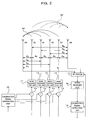
- FIG. 7 is a block diagram showing a construction (for downlink) of a radio transmitter to which an array antenna calibration apparatus of a fifth embodiment of the present invention is applied.
- the radio transmitter of FIG. 7 differs from the construction in FIG.
- circulators 21, which serve as split means for splitting a part of a received signal from the main received signal, are provided, one for each of the antenna elements E0, E1, E2, and E3, and in that an RF switch 17', which selectively outputs the signals from the antenna elements E0, E1, E2, and E3 (circulators 21) and from the dummy antenna elements DA and DB to the radio receiver unit 18, is provided instead of the RF switch 17.
- RF switch 17' which selectively outputs the signals from the antenna elements E0, E1, E2, and E3 (circulators 21) and from the dummy antenna elements DA and DB to the radio receiver unit 18, is provided instead of the RF switch 17.
- Like reference numbers and characters designate similar parts or elements throughout several views of the embodiments, so their detailed description is omitted here.
- This construction makes it possible for the antenna elements E0, E1, E2, and E3, in addition to the dummy antenna elements DA and DB, to receive calibration signals, thereby realizing more flexible calibration of the antenna elements E0, E1, E2, and E3.
- the antenna elements DA and E2 disposed on either side of the adjacent antenna elements E0 and E1, can be used for calibration. More specifically, signals emitted from the antenna elements E0 and E1 are received by the dummy antenna element DA. Likewise, signals emitted from the antenna elements E0 and E1 are also received by the antenna element E2. In this manner, as with the first embodiment, the calibration signal phase difference is detected, and on the basis of the thus detected phase difference, the phase shifters 12 are individually controlled, so that each antenna element is accurately calibrated without causing calibration error due to antenna element interval deviation.
- FIG. 8 is a block diagram showing a construction (for uplink) of a radio receiver to which an array antenna calibration apparatus of a sixth embodiment of the present invention is applied.
- the radio receiver of FIG. 8 differs from the construction already described with reference to FIG.
- This construction makes it possible for the antenna elements E0, E1, E2, and E3, in addition to the dummy antenna elements DA and DB, to send calibration signals, thereby realizing more flexible calibration of the antenna elements E0, E1, E2, and E3.
- the antenna elements DA and E2 disposed on either side of the adjacent antenna elements E0 and E1, can be used for calibration. More specifically, a signal emitted from the antenna element DA is received by the antenna elements E0 and E1. Likewise, a signal emitted from the antenna element E2 is also received by the antenna elements E0 and E1. In this manner, as with the second embodiment, the calibration signal phase difference is detected, and on the basis of the thus detected phase difference, the phase shifters 32 are individually controlled, so that each antenna element is accurately calibrated without causing calibration error due to antenna element interval deviation.
- dummy antenna elements DA and DB which are normally provided for shaping an emission pattern, are used as antenna elements for receiving and sending calibration signals, and calibration can be carried out from two directions, so that accurate, antenna-element-interval-independent calibration is realized. Accordingly, antenna element interval deviation is allowed, and array antenna yields are reduced, thereby contributing to reduction of the manufacturing cost.
Landscapes
- Variable-Direction Aerials And Aerial Arrays (AREA)
- Radio Transmission System (AREA)
Applications Claiming Priority (1)
| Application Number | Priority Date | Filing Date | Title |
|---|---|---|---|
| JP2005147249A JP4478606B2 (ja) | 2005-05-19 | 2005-05-19 | リニアアレイアンテナの校正装置及び校正方法 |
Publications (2)
| Publication Number | Publication Date |
|---|---|
| EP1724875A1 true EP1724875A1 (fr) | 2006-11-22 |
| EP1724875B1 EP1724875B1 (fr) | 2011-07-27 |
Family
ID=36917287
Family Applications (1)
| Application Number | Title | Priority Date | Filing Date |
|---|---|---|---|
| EP05255348A Expired - Fee Related EP1724875B1 (fr) | 2005-05-19 | 2005-09-01 | Dispositif et procédé d'étalonnage d'un réseau d'antennes |
Country Status (3)
| Country | Link |
|---|---|
| US (1) | US7545321B2 (fr) |
| EP (1) | EP1724875B1 (fr) |
| JP (1) | JP4478606B2 (fr) |
Cited By (7)
| Publication number | Priority date | Publication date | Assignee | Title |
|---|---|---|---|---|
| WO2008074925A1 (fr) * | 2006-12-21 | 2008-06-26 | Nokia Corporation | Procédé et système de communication |
| WO2009027724A1 (fr) * | 2007-08-31 | 2009-03-05 | Bae Systems Plc | Etalonnage d'antennes |
| WO2009027725A1 (fr) * | 2007-08-31 | 2009-03-05 | Bae Systems Plc | Etalonnage d'antennes |
| WO2009027723A1 (fr) * | 2007-08-31 | 2009-03-05 | Bae Systems Plc | Etalonnage d'antennes |
| US7990312B2 (en) | 2007-08-31 | 2011-08-02 | Bae Systems Plc | Antenna calibration |
| WO2013050085A1 (fr) * | 2011-10-07 | 2013-04-11 | Telefonaktiebolaget L M Ericsson (Publ) | Appareil et procédé d'utilisation avec un réseau d'antennes |
| EP3790111A4 (fr) * | 2018-07-06 | 2021-05-19 | Huawei Technologies Co., Ltd. | Procédé destiné à étalonner une antenne de réseau équiphase, et appareil associé |
Families Citing this family (60)
| Publication number | Priority date | Publication date | Assignee | Title |
|---|---|---|---|---|
| JP4516358B2 (ja) * | 2004-05-26 | 2010-08-04 | 富士通株式会社 | 無線基地局装置および無線通信方法 |
| JP2006005525A (ja) * | 2004-06-16 | 2006-01-05 | Nec Corp | 送信装置 |
| JP2007336463A (ja) * | 2006-06-19 | 2007-12-27 | Sony Corp | 情報処理装置、方法、およびプログラム |
| US7873332B2 (en) * | 2006-12-06 | 2011-01-18 | Broadcom Corporation | Method and system for mitigating a voltage standing wave ratio |
| US7822398B2 (en) * | 2007-09-17 | 2010-10-26 | Intel Corporation | Device, system, and method of phased-array calibration |
| EP2040333A1 (fr) * | 2007-09-24 | 2009-03-25 | Astrium GmbH | Procédé et dispositif d'étalonnage d'une antenne de réseau |
| JP2010054218A (ja) * | 2008-08-26 | 2010-03-11 | Toyota Central R&D Labs Inc | デジタル信号処理装置及びそれを有するフェーズドアレイレーダ |
| US8633851B2 (en) * | 2010-02-19 | 2014-01-21 | Honeywell International Inc. | Low power, space combined, phased array radar |
| US8897717B2 (en) | 2010-07-28 | 2014-11-25 | Honeywell International Inc. | Dual-feed antenna array with integral comparison circuit for phase and amplitude calibration |
| JP5620757B2 (ja) * | 2010-09-01 | 2014-11-05 | 株式会社豊田中央研究所 | レーダ装置 |
| JP5666717B2 (ja) * | 2010-12-01 | 2015-02-12 | テレフオンアクチーボラゲット エル エム エリクソン(パブル) | 少なくとも1つのキャリブレーションパラメータを取得するための方法、及び、アンテナアレイ |
| JP5246250B2 (ja) * | 2010-12-09 | 2013-07-24 | 株式会社デンソー | フェーズドアレイアンテナの位相校正方法及びフェーズドアレイアンテナ |
| JP5104938B2 (ja) * | 2010-12-09 | 2012-12-19 | 株式会社デンソー | フェーズドアレイアンテナの位相校正方法及びフェーズドアレイアンテナ |
| ITTO20111108A1 (it) * | 2010-12-22 | 2012-06-23 | Selex Sistemi Integrati Spa | Calibrazione di antenne a schiera attive a scansione elettronica del fascio |
| US20140225805A1 (en) | 2011-03-15 | 2014-08-14 | Helen K. Pan | Conformal phased array antenna with integrated transceiver |
| US10439684B2 (en) * | 2012-12-31 | 2019-10-08 | Futurewei Technologies, Inc. | Smart antenna platform for indoor wireless local area networks |
| US9893715B2 (en) * | 2013-12-09 | 2018-02-13 | Shure Acquisition Holdings, Inc. | Adaptive self-tunable antenna system and method |
| FR3030774B1 (fr) * | 2014-12-19 | 2017-01-20 | Thales Sa | Procede de determination de parametres d'un filtre de compression et radar multivoies associe |
| US10179057B2 (en) | 2015-05-28 | 2019-01-15 | George Kramer | Tracheobronchial Y-stents, delivery catheters and delivery apparatus, and methods for delivering bronchial Y-stents |
| US9673965B2 (en) * | 2015-09-10 | 2017-06-06 | Blue Danube Systems, Inc. | Calibrating a serial interconnection |
| KR101628183B1 (ko) * | 2015-11-11 | 2016-06-08 | 국방과학연구소 | 배열안테나를 구비하는 레이더 및 그것의 위상 교정 방법 |
| CN108141256B (zh) | 2016-02-04 | 2021-01-08 | 华为技术有限公司 | 天线阵列的相位调整方法及装置 |
| WO2017145257A1 (fr) | 2016-02-23 | 2017-08-31 | 三菱電機株式会社 | Dispositif d'antenne réseau et son procédé d'étalonnage |
| WO2017175190A1 (fr) | 2016-04-07 | 2017-10-12 | Uhnder, Inc. | Transmission adaptative et annulation de brouillage pour radar mimo |
| US9846228B2 (en) | 2016-04-07 | 2017-12-19 | Uhnder, Inc. | Software defined automotive radar systems |
| US10261179B2 (en) | 2016-04-07 | 2019-04-16 | Uhnder, Inc. | Software defined automotive radar |
| US9954955B2 (en) | 2016-04-25 | 2018-04-24 | Uhnder, Inc. | Vehicle radar system with a shared radar and communication system |
| US9806914B1 (en) | 2016-04-25 | 2017-10-31 | Uhnder, Inc. | Successive signal interference mitigation |
| US9575160B1 (en) | 2016-04-25 | 2017-02-21 | Uhnder, Inc. | Vehicular radar sensing system utilizing high rate true random number generator |
| WO2017187306A1 (fr) | 2016-04-25 | 2017-11-02 | Uhnder, Inc. | Filtrage adaptatif pour atténuation d'interférence fmcw dans des systèmes de radar pmcw |
| WO2017187278A1 (fr) | 2016-04-25 | 2017-11-02 | Uhnder, Inc. | Atténuation d'interférences entre ondes entretenues à modulation de phase |
| WO2017187242A1 (fr) | 2016-04-25 | 2017-11-02 | Uhnder, Inc. | Micro-doppler à balayage multiple à la demande pour véhicule |
| US9945935B2 (en) | 2016-04-25 | 2018-04-17 | Uhnder, Inc. | Digital frequency modulated continuous wave radar using handcrafted constant envelope modulation |
| US10573959B2 (en) | 2016-04-25 | 2020-02-25 | Uhnder, Inc. | Vehicle radar system using shaped antenna patterns |
| US9791551B1 (en) | 2016-04-25 | 2017-10-17 | Uhnder, Inc. | Vehicular radar system with self-interference cancellation |
| JP2017212594A (ja) * | 2016-05-25 | 2017-11-30 | 富士通株式会社 | 無線通信装置及びキャリブレーション方法 |
| US9753121B1 (en) | 2016-06-20 | 2017-09-05 | Uhnder, Inc. | Power control for improved near-far performance of radar systems |
| US9923712B2 (en) | 2016-08-01 | 2018-03-20 | Movandi Corporation | Wireless receiver with axial ratio and cross-polarization calibration |
| JP6860777B2 (ja) | 2016-08-22 | 2021-04-21 | 富士通株式会社 | 無線通信装置、及び位相調整方法 |
| US10291296B2 (en) * | 2016-09-02 | 2019-05-14 | Movandi Corporation | Transceiver for multi-beam and relay with 5G application |
| WO2018051288A1 (fr) | 2016-09-16 | 2018-03-22 | Uhnder, Inc. | Configuration de radar virtuel pour réseau 2d |
| US10199717B2 (en) | 2016-11-18 | 2019-02-05 | Movandi Corporation | Phased array antenna panel having reduced passive loss of received signals |
| WO2018146530A1 (fr) | 2017-02-10 | 2018-08-16 | Uhnder, Inc. | Corrélation basée sur une fft à complexité réduite pour un radar automobile |
| WO2018146632A1 (fr) | 2017-02-10 | 2018-08-16 | Uhnder, Inc. | Mise en mémoire tampon de données radar |
| US11454697B2 (en) | 2017-02-10 | 2022-09-27 | Uhnder, Inc. | Increasing performance of a receive pipeline of a radar with memory optimization |
| US10484078B2 (en) | 2017-07-11 | 2019-11-19 | Movandi Corporation | Reconfigurable and modular active repeater device |
| US11105890B2 (en) | 2017-12-14 | 2021-08-31 | Uhnder, Inc. | Frequency modulated signal cancellation in variable power mode for radar applications |
| US11177567B2 (en) * | 2018-02-23 | 2021-11-16 | Analog Devices Global Unlimited Company | Antenna array calibration systems and methods |
| US10446930B1 (en) | 2018-06-25 | 2019-10-15 | Nxp B.V. | Antenna combination device |
| JP7091197B2 (ja) | 2018-09-10 | 2022-06-27 | 株式会社東芝 | 無線通信装置及び無線通信システム |
| US11474225B2 (en) | 2018-11-09 | 2022-10-18 | Uhnder, Inc. | Pulse digital mimo radar system |
| US11349208B2 (en) | 2019-01-14 | 2022-05-31 | Analog Devices International Unlimited Company | Antenna apparatus with switches for antenna array calibration |
| WO2020183392A1 (fr) | 2019-03-12 | 2020-09-17 | Uhnder, Inc. | Procédé et appareil d'atténuation du bruit basse fréquence dans des systèmes radar |
| US11404779B2 (en) | 2019-03-14 | 2022-08-02 | Analog Devices International Unlimited Company | On-chip phased array calibration systems and methods |
| EP3772773A1 (fr) * | 2019-08-08 | 2021-02-10 | Nokia Solutions and Networks Oy | Boîtier d'antenne |
| JP2021106306A (ja) * | 2019-12-26 | 2021-07-26 | 株式会社東芝 | 電子装置及び方法 |
| WO2021144710A2 (fr) | 2020-01-13 | 2021-07-22 | Uhnder, Inc. | Procédé et système pour le fonctionnement multi-puce de systèmes radar |
| US11450952B2 (en) | 2020-02-26 | 2022-09-20 | Analog Devices International Unlimited Company | Beamformer automatic calibration systems and methods |
| EP4040600A1 (fr) * | 2021-02-04 | 2022-08-10 | Urugus S.A. | Système et dispositif de communication définis par logiciel |
| CN113541744B (zh) * | 2021-07-13 | 2022-07-08 | 中国科学院软件研究所 | 一种物联网LoRa信号的波束成形多目标感知方法及系统 |
Citations (4)
| Publication number | Priority date | Publication date | Assignee | Title |
|---|---|---|---|---|
| EP0805514A2 (fr) | 1996-05-02 | 1997-11-05 | HE HOLDINGS, INC. dba HUGHES ELECTRONICS | Auto-calibration d'antenne-réseaux avec couplage mutuel non-uniforme des éléments d'antennes et orientation arbitraire du treillis d'antennes |
| EP1294047A2 (fr) | 2001-09-17 | 2003-03-19 | Nec Corporation | Dispositif et procédé d'étalonnage d'un réseau d'antennes |
| EP1367670A1 (fr) * | 1998-07-13 | 2003-12-03 | NTT Mobile Communications Network Inc. | Calibration pour un réseau d'antennes adaptatif |
| WO2004023600A1 (fr) | 2002-08-19 | 2004-03-18 | Kathrein-Werke Kg | Dispositif d'etalonnage destine a un reseau d'antennes et procede d'etalonnage de ce reseau d'antennes |
Family Cites Families (4)
| Publication number | Priority date | Publication date | Assignee | Title |
|---|---|---|---|---|
| JPH0793534B2 (ja) | 1989-04-05 | 1995-10-09 | 三菱電機株式会社 | アンテナ装置 |
| JP2003021862A (ja) | 2001-07-10 | 2003-01-24 | Kyocera Corp | カメラの外装構造 |
| JP2003218621A (ja) * | 2002-01-21 | 2003-07-31 | Nec Corp | アレーアンテナの校正装置及び校正方法 |
| US7359449B2 (en) * | 2004-10-05 | 2008-04-15 | Kamilo Feher | Data communication for wired and wireless communication |
-
2005
- 2005-05-19 JP JP2005147249A patent/JP4478606B2/ja not_active Expired - Fee Related
- 2005-08-24 US US11/209,626 patent/US7545321B2/en not_active Expired - Fee Related
- 2005-09-01 EP EP05255348A patent/EP1724875B1/fr not_active Expired - Fee Related
Patent Citations (4)
| Publication number | Priority date | Publication date | Assignee | Title |
|---|---|---|---|---|
| EP0805514A2 (fr) | 1996-05-02 | 1997-11-05 | HE HOLDINGS, INC. dba HUGHES ELECTRONICS | Auto-calibration d'antenne-réseaux avec couplage mutuel non-uniforme des éléments d'antennes et orientation arbitraire du treillis d'antennes |
| EP1367670A1 (fr) * | 1998-07-13 | 2003-12-03 | NTT Mobile Communications Network Inc. | Calibration pour un réseau d'antennes adaptatif |
| EP1294047A2 (fr) | 2001-09-17 | 2003-03-19 | Nec Corporation | Dispositif et procédé d'étalonnage d'un réseau d'antennes |
| WO2004023600A1 (fr) | 2002-08-19 | 2004-03-18 | Kathrein-Werke Kg | Dispositif d'etalonnage destine a un reseau d'antennes et procede d'etalonnage de ce reseau d'antennes |
Cited By (14)
| Publication number | Priority date | Publication date | Assignee | Title |
|---|---|---|---|---|
| WO2008074925A1 (fr) * | 2006-12-21 | 2008-06-26 | Nokia Corporation | Procédé et système de communication |
| US8208963B2 (en) | 2006-12-21 | 2012-06-26 | Nokia Corporation | Communication method and system |
| US8004457B2 (en) | 2007-08-31 | 2011-08-23 | Bae Systems Plc | Antenna calibration |
| WO2009027723A1 (fr) * | 2007-08-31 | 2009-03-05 | Bae Systems Plc | Etalonnage d'antennes |
| US7990312B2 (en) | 2007-08-31 | 2011-08-02 | Bae Systems Plc | Antenna calibration |
| US8004456B2 (en) | 2007-08-31 | 2011-08-23 | Bae Systems Plc | Antenna calibration |
| WO2009027725A1 (fr) * | 2007-08-31 | 2009-03-05 | Bae Systems Plc | Etalonnage d'antennes |
| US8085189B2 (en) | 2007-08-31 | 2011-12-27 | Bae Systems Plc | Antenna calibration |
| WO2009027724A1 (fr) * | 2007-08-31 | 2009-03-05 | Bae Systems Plc | Etalonnage d'antennes |
| AU2008291898B2 (en) * | 2007-08-31 | 2013-09-05 | Bae Systems Plc | Antenna calibration |
| WO2013050085A1 (fr) * | 2011-10-07 | 2013-04-11 | Telefonaktiebolaget L M Ericsson (Publ) | Appareil et procédé d'utilisation avec un réseau d'antennes |
| US9712191B2 (en) | 2011-10-07 | 2017-07-18 | Telefonaktiebolaget L M Ericsson | Apparatus and method for use with antenna array |
| EP3790111A4 (fr) * | 2018-07-06 | 2021-05-19 | Huawei Technologies Co., Ltd. | Procédé destiné à étalonner une antenne de réseau équiphase, et appareil associé |
| US11811147B2 (en) | 2018-07-06 | 2023-11-07 | Huawei Technologies Co., Ltd. | Method for calibrating phased array antenna and related apparatus |
Also Published As
| Publication number | Publication date |
|---|---|
| JP4478606B2 (ja) | 2010-06-09 |
| US7545321B2 (en) | 2009-06-09 |
| EP1724875B1 (fr) | 2011-07-27 |
| JP2006325033A (ja) | 2006-11-30 |
| US20060273959A1 (en) | 2006-12-07 |
Similar Documents
| Publication | Publication Date | Title |
|---|---|---|
| EP1724875B1 (fr) | Dispositif et procédé d'étalonnage d'un réseau d'antennes | |
| US7340248B2 (en) | Calibration apparatus | |
| US6157343A (en) | Antenna array calibration | |
| EP2139070B1 (fr) | Appareil émetteur-récepteur doté d'une antenne réseau adaptative | |
| CN1830159B (zh) | 天线阵列校准装置和方法 | |
| AU691295B2 (en) | Antenna array calibration | |
| US7181245B2 (en) | Wireless transmitter, transceiver and method | |
| EP1438768B1 (fr) | Etalonnage en fonction de la frequence d'un systeme radio large bande utilisant des canaux a bande etroite | |
| EP0840961B1 (fr) | Appareil d'auto-etalonnage et procede afferent pour unite de communication | |
| US20120020396A1 (en) | Calibration of smart antenna systems | |
| WO2002095983A1 (fr) | Emetteur/recepteur a antenne reseau et procede pour l'etalonner | |
| EP1178562A1 (fr) | Etallonage d'un réseau d'antennes | |
| US7020445B1 (en) | Wireless base station system, and wireless transmission method | |
| KR19990088045A (ko) | 기지국장치및송신전력제어방법 | |
| US6865377B1 (en) | Combined open and closed loop beam forming in a multiple array radio communication system | |
| US6232927B1 (en) | Array antenna apparatus for use in spread spectrum communications with a particular interval between antenna elements | |
| US6611511B1 (en) | Cellular telephone communication system using sector splitting for improved performance | |
| US7039016B1 (en) | Calibration of wideband radios and antennas using a narrowband channel | |
| US6600935B1 (en) | Radio transmission device and transmission directivity adjusting method | |
| WO2008048788A2 (fr) | Système de communication sans fil avec des conceptions de diversité de transmission | |
| WO2001095645A1 (fr) | Structure de reutilisation sans fil cellulaire permettant une communication par multiplexage spatial et diversifiee |
Legal Events
| Date | Code | Title | Description |
|---|---|---|---|
| PUAI | Public reference made under article 153(3) epc to a published international application that has entered the european phase |
Free format text: ORIGINAL CODE: 0009012 |
|
| AK | Designated contracting states |
Kind code of ref document: A1 Designated state(s): AT BE BG CH CY CZ DE DK EE ES FI FR GB GR HU IE IS IT LI LT LU LV MC NL PL PT RO SE SI SK TR |
|
| AX | Request for extension of the european patent |
Extension state: AL BA HR MK YU |
|
| 17P | Request for examination filed |
Effective date: 20070521 |
|
| AKX | Designation fees paid |
Designated state(s): DE FR GB IT |
|
| 17Q | First examination report despatched |
Effective date: 20090721 |
|
| GRAP | Despatch of communication of intention to grant a patent |
Free format text: ORIGINAL CODE: EPIDOSNIGR1 |
|
| GRAS | Grant fee paid |
Free format text: ORIGINAL CODE: EPIDOSNIGR3 |
|
| GRAA | (expected) grant |
Free format text: ORIGINAL CODE: 0009210 |
|
| AK | Designated contracting states |
Kind code of ref document: B1 Designated state(s): DE FR GB IT |
|
| REG | Reference to a national code |
Ref country code: GB Ref legal event code: FG4D |
|
| REG | Reference to a national code |
Ref country code: DE Ref legal event code: R096 Ref document number: 602005029177 Country of ref document: DE Effective date: 20110922 |
|
| PGFP | Annual fee paid to national office [announced via postgrant information from national office to epo] |
Ref country code: FR Payment date: 20110817 Year of fee payment: 7 |
|
| PG25 | Lapsed in a contracting state [announced via postgrant information from national office to epo] |
Ref country code: IT Free format text: LAPSE BECAUSE OF FAILURE TO SUBMIT A TRANSLATION OF THE DESCRIPTION OR TO PAY THE FEE WITHIN THE PRESCRIBED TIME-LIMIT Effective date: 20110727 |
|
| PLBE | No opposition filed within time limit |
Free format text: ORIGINAL CODE: 0009261 |
|
| STAA | Information on the status of an ep patent application or granted ep patent |
Free format text: STATUS: NO OPPOSITION FILED WITHIN TIME LIMIT |
|
| 26N | No opposition filed |
Effective date: 20120502 |
|
| REG | Reference to a national code |
Ref country code: DE Ref legal event code: R097 Ref document number: 602005029177 Country of ref document: DE Effective date: 20120502 |
|
| GBPC | Gb: european patent ceased through non-payment of renewal fee |
Effective date: 20120901 |
|
| REG | Reference to a national code |
Ref country code: FR Ref legal event code: ST Effective date: 20130531 |
|
| PG25 | Lapsed in a contracting state [announced via postgrant information from national office to epo] |
Ref country code: DE Free format text: LAPSE BECAUSE OF NON-PAYMENT OF DUE FEES Effective date: 20130403 Ref country code: GB Free format text: LAPSE BECAUSE OF NON-PAYMENT OF DUE FEES Effective date: 20120901 |
|
| PG25 | Lapsed in a contracting state [announced via postgrant information from national office to epo] |
Ref country code: FR Free format text: LAPSE BECAUSE OF NON-PAYMENT OF DUE FEES Effective date: 20121001 |
|
| REG | Reference to a national code |
Ref country code: DE Ref legal event code: R119 Ref document number: 602005029177 Country of ref document: DE Effective date: 20130403 |